EP4011193A1 - Anordnung aus einem elektrowerkzeug und einem handhabungsgerät - Google Patents
Anordnung aus einem elektrowerkzeug und einem handhabungsgerät Download PDFInfo
- Publication number
- EP4011193A1 EP4011193A1 EP21212737.7A EP21212737A EP4011193A1 EP 4011193 A1 EP4011193 A1 EP 4011193A1 EP 21212737 A EP21212737 A EP 21212737A EP 4011193 A1 EP4011193 A1 EP 4011193A1
- Authority
- EP
- European Patent Office
- Prior art keywords
- power tool
- handling device
- arrangement
- guide groove
- projection
- Prior art date
- Legal status (The legal status is an assumption and is not a legal conclusion. Google has not performed a legal analysis and makes no representation as to the accuracy of the status listed.)
- Granted
Links
Images



Classifications
-
- A—HUMAN NECESSITIES
- A01—AGRICULTURE; FORESTRY; ANIMAL HUSBANDRY; HUNTING; TRAPPING; FISHING
- A01G—HORTICULTURE; CULTIVATION OF VEGETABLES, FLOWERS, RICE, FRUIT, VINES, HOPS OR SEAWEED; FORESTRY; WATERING
- A01G3/00—Cutting implements specially adapted for horticultural purposes; Delimbing standing trees
- A01G3/06—Hand-held edge trimmers or shears for lawns
- A01G3/067—Motor-driven shears for lawns
Definitions
- the invention relates to an arrangement of a power tool having a working device and a handling device serving to support and move the power tool on a plane.
- the CN 201146705 Y describes a similar grass shear that can be used with a push cart and an extension sheave.
- the extension rod is inserted into a recess in the grass shears.
- the DE 24 38 360 A1 describes a power grass shears that can be connected and disconnected to a roller stick, which consists of an angled rod and rollers mounted near the angle point.
- U.S. 3,759,020 A discloses a hand-held powered grass shears for lawn trimming.
- the guide groove and the projection of the arrangement according to the invention which is suitable for engaging in the guide groove, enable the power tool to be easily pushed into a corresponding receptacle of the handling device or, conversely, the handling device to the power tool, so that even an inexperienced user is able to move the power tool easily Way to connect to the handling device.
- the locking element provided in the arrangement according to the invention ensures that the power tool is held securely on the manipulator.
- the arrangement according to the invention also allows the power tool to be controlled easily by the handling device, since these two elements are firmly and securely connected to one another, so that every movement introduced into the handling device results in a corresponding movement of the power tool is implemented.
- the longitudinal axis of the guide rod can be arranged in the angle range according to the invention of 60° to 90° to the plane on which the power tool is supported and at least in one angle of the angle range the wheel axis of the Power tool intersects substantially perpendicularly and thus runs steeply to the plane and perpendicular to the wheel axis, a movement of the guide rod originating from an operator is advantageously precisely converted into a movement of the working device.
- the wheel axle acts as the axis of rotation and a working distance of the working device from the plane can be set with an advantageously small gear reduction due to the small distance between the working device and the wheel axle.
- the wheel arranged in the respective deflection direction acts as a fulcrum, with the arrangement being able to be easily tilted laterally against gravity due to the steep course of the longitudinal axis of the guide rod to the plane through the operator.
- a particular advantage of the solution according to the invention is that the handling device can be attached to the power tool independently of the location at which a rechargeable battery that supplies it with electrical power is located. As a result, it is not necessary to dismantle the battery in order to attach the power tool to the handling device.
- a pivoting device can be provided, by means of which the longitudinal axis of the guide rod can be pivoted in a pivoting range relative to the plane on which the power tool is supported.
- the angle through which the pivoting device can be pivoted within the pivoting range can assume angles that are also outside the angular range according to the invention. It can be provided that the pivoting range completely encompasses the angle range and goes beyond it at one or both end ranges or is identical to it or is only a partial range of the angle range.
- the pivoting device enables the longitudinal axis of the guide rod to be arranged within the angular range according to the invention.
- the fact that the pivoting range at least partially overlaps with the angular range according to the invention ensures that the operator can set the angle in the angular range according to the invention is made possible in order to be able to benefit from the advantageous mechanical effects occurring in this area.
- the at least one guide groove is provided on a housing part of the power tool, and that the at least one projection is provided on the handling device. This enables the solution according to the invention to be implemented with very little intervention in the power tool. In principle, however, it would also be possible to provide the at least one guide groove on the handling device and the at least one projection on the power tool.
- a particularly safe guidance and at the same time a particularly reliable mounting of the power tool on the manipulator is obtained if at least two guide grooves lying opposite one another and respective projections engaging in the guide grooves are provided.
- the guide grooves and the projections have an at least approximately rectangular cross section.
- An alternative embodiment can consist in the fact that exactly one guide groove and exactly one projection are provided, the guide groove having two undercuts and the projection having respective engagement elements projecting into the undercuts.
- the power tool and the manipulator In order to enable the power tool to be operated via the manipulator, provision can also be made for the power tool and the manipulator to have respective contact elements.
- the contact elements of the handling device and/or the power tool are designed as spring elements, then when the power tool is connected to the handling device, they are automatically contacted, which makes it considerably easier to connect the power tool to the handling device.
- the device has a recess which is provided for engagement by the locking element, an even more reliable holding of the power tool on the manipulator is ensured.
- Attaching the power tool to the manipulator can also be simplified by providing a spring element which prestresses the locking element in a direction that locks the power tool to the manipulator. In this way, it is only necessary to move the power tool relative to the manipulator until the spring element ensures that the locking element is locked.
- the power tool 1 shows a power tool 1, in the present case a grass shears.
- the power tool 1 has a housing 2 which can be divided into a handle housing area 2a and a motor housing area 2b. While a rechargeable battery (not shown) can be attached to the handle housing area 2a, an in 8 Working device 101 shown, which, for example, as in 8 can be designed as a cutting blade, are attached.
- a guide groove 3 can be seen on the motor housing area 2b of the housing 2, which is part of a device 4, described in more detail below, for holding the power tool 1 on one in the Figures 3, 4 and 5 illustrated handling device 5 is.
- Out of 2 1 shows that on both sides of the motor housing portion 2b of the housing 2, respective guide grooves 3 are provided which face each other.
- a contact element 6 of the power tool 1 located on the upper side of the motor housing area 2b of the housing 2 can be seen.
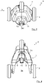
- the handling device 5 shown is designed as a so-called push cart and has two wheels 8 arranged on both sides of a housing 7 .
- the wheels 8 make it possible to support the power tool 1 held on the manipulator 5 by means of the device 4 on a plane and to move it relative to the same. In certain cases, the wheels 8 could also be dispensed with if the level or the ground on which the power tool 1 is to be moved allows this.
- the housing 7 of the handling device 5 has at least one projection 9 which is suitable for engaging in the guide groove 3 of the housing 2 of the power tool 1 and which in figure 5 as well as, very schematically, in 7 is shown.
- respective projections 9 are provided on both sides of the housing 7, which are arranged in such a way that they engage in the guide grooves 3 when the power tool 1 is pushed into a receptacle 5a of the handling device 5 formed in the housing 7 .
- the engagement of the projections 9 of the handling device 5 in the guide grooves 3 of the power tool 1 can be seen.
- the handling device 5 and in particular the at least one projection 9 on the same can be adapted to the respective requirements of the power tool 1 or the at least one guide groove 3 thereof.
- exactly one guide groove 3 and exactly one projection 9 can be provided.
- the guide groove 3 can have two undercuts and the projection 9 have respective engaging elements projecting into the undercuts.
- the handling device 5 has a locking element 10 which is used to lock the power tool 1 to the handling device 5 .
- the locking element 10 is mounted on the housing 7 of the handling device 5 such that it can rotate about an axis of rotation 11 and has an in figure 5 illustrated hook 10a, which is intended to engage in a corresponding recess 12 in the power tool 1.
- the recess 12 in the housing 2, in the present case in the motor housing area 2b, of the power tool 1 is in 2 to recognize.
- the recess 12 for the hook 10a of the locking element 10 can be formed, for example, as a simple undercut.
- the locking element 10 has a spring element, not shown, which prestresses the locking element 10 in a direction that locks the power tool 1 on the handling device 5 .
- the spring element can be designed as a torsion spring, which is arranged around the axis of rotation 11 of the locking element 10 and which acts on the locking element 10 in such a way that the hook 10a thereof is pressed in the direction of the power tool 1 .
- the hook 10a of the locking element 10 automatically engages in the recess 12 of the power tool 1 when the power tool 1 is pushed into the handling device 5 .
- the handling device 5 also has a contact element 13 provided for contacting the contact element 6 of the power tool 1, which is located in an area in which it comes into contact with the contact element 6 of the power tool 1 in contact comes.
- One of the contact elements 6 or 13 is preferably designed as a spring element. In the present case, this is the contact element 13 of the handling device 5.
- a spring element for one of the contact elements 6 or 13, it is basically also possible to use plugs or the like.
- the handling device 5 is in the area of the center of gravity and in the vicinity of the position shown in the exemplary embodiment 8 arranged as a cutting blade working device of the power tool 1 or locked on the same.
- the attachment point of the power tool 1 By arranging the attachment point of the power tool 1 on the handling device 5 in the immediate vicinity of the cutting blade, the power tool 1 can be controlled very easily by the handling device 5 .
- This point of attachment or pivot is also close to the axles of the wheels 8, i.e. their point of attachment to the housing 7.
- power tool 1 could, for example, also be designed as a grinding tool, e.g. as an orbital or random orbit sander, as a sawing tool, e.g. as a saber saw or jigsaw, or as another power tool that can be accommodated in handling device 5 so that the Users can get into areas that he could not reach without the handling device 5.
- the working device 101 can be designed accordingly.
- the arrangement 100 has the device 4 for holding the power tool 1 on the handling device 5, which has the at least one guide groove 3 on the power tool 1 or on the handling device 5, the at least one projection 9 suitable for engaging in the guide groove 3 on the handling device 5 or on the power tool 1 and the locking element 10 for locking the power tool 1 on the handling device 5 .
- the handling device 5 is designed as a sliding carriage with a guide rod 102 for manual guidance and has two wheels 8 arranged on both sides of the housing 7 of the handling device 5 .
- the wheels 8 are on one in which in 8 illustrated embodiment virtual, wheel axle 104, which is represented by a dashed line, arranged.
- an attachment point of the power tool 1 on the handling device 5 is arranged in the immediate vicinity of the working device 101 and in the vicinity of the wheel axle 104 in such a way that a longitudinal axis of the guide rod 102 is in an angular range of 60° to 90° to the plane on which the Power tool 1 is supported, can be arranged and at least at one angle of the angular range, the wheel axle 104 of the power tool 1 intersects essentially perpendicularly.
- the wheels 8 are attached to respective plug-in axles that are arranged laterally on the housing 7 and protrude from it, so that an interior area of the handling device 5 is not traversed by a continuous axle, which could make it difficult to attach the power tool 1 .
- the two quick-release axles are arranged along the common virtual wheel axle 104 .
- the exemplary embodiment illustrated also has a pivoting device 105, by means of which the longitudinal axis of the guide rod 102 can be pivoted in a pivoting range relative to the plane on which the power tool 1 is supported.
- the guide rod 102 in the 8 illustrated embodiment an adjustment device 106 for adjusting the length of the guide rod 102 and a grip element 107 for holding the assembly 100 securely.
Landscapes
- Life Sciences & Earth Sciences (AREA)
- Biodiversity & Conservation Biology (AREA)
- Ecology (AREA)
- Forests & Forestry (AREA)
- Environmental Sciences (AREA)
- Handcart (AREA)
- Manipulator (AREA)
Abstract
- einer Vorrichtung (4) zur Halterung des Elektrowerkzeugs (1) an dem Handhabungsgerät (5), welche wenigstens eine Führungsnut (3) an dem Elektrowerkzeug (1) oder an dem Handhabungsgerät (5), wenigstens einen zum Eingriff in die Führungsnut (3) geeigneten Vorsprung (9) an dem Handhabungsgerät (5) oder an dem Elektrowerkzeug (1) und ein Verriegelungselement (10) zur Verriegelung des Elektrowerkzeugs (1) an dem Handhabungsgerät (5) aufweist; wobei
- das Handhabungsgerät (5) als Schiebewagen mit einer Führungsstange (102) zur händischen Führung ausgebildet ist und zwei beiderseits eines Gehäuses (7) des Handhabungsgeräts (5) auf einer, insbesondere virtuellen, Radachse (104) angeordnete Räder (8) aufweist, wobei
- ein Anbringungspunkt des Elektrowerkzeugs (1) an dem Handhabungsgerät (5) in unmittelbarer Nähe zu der Arbeitseinrichtung (101) sowie in der Nähe der Radachse (104) derart angeordnet ist, dass
- eine Längsachse der Führungsstange (102) in einem Winkelbereich von 60° bis 90° zu der Ebene, an der das Elektrowerkzeug (1) abgestützt ist, anordenbar ist und zumindest in einem Winkel des Winkelbereichs die Radachse (104) des Elektrowerkzeuges (1) im Wesentlichen senkrecht schneidet.
Description
- Die Erfindung betrifft eine Anordnung aus einem eine Arbeitseinrichtung aufweisenden Elektrowerkzeug und einem zur Abstützung und Bewegung des Elektrowerkzeugs dienenden Handhabungsgerät an einer Ebene.
- Aus der
EP 1 479 285 B1 ist eine elektromotorisch betriebene Grasschere bekannt, die ein Gehäuse mit einer Aufnahmeöffnung für einen einsteckbaren Stiel aufweist. - Die
CN 201146705 Y beschreibt eine ähnliche Grasschere, die mit einem Schiebewagen und einer Verlängerungsscheibe benutzt werden kann. Die Verlängerungsstange wird in eine Ausnehmung der Grasschere eingesteckt. - Aus der
DE 10 2012 214 715 A1 ist eine ähnliche Grasschere bekannt, bei der eine Führungsstange gelenkig mit derselben verbunden ist. Dabei werden Verbindungsbolzen in entsprechende Ausnehmungen des Gehäuses der Grasschere eingeführt. - Die
DE 24 38 360 A1 beschreibt eine Motor-Grasschere, die mit einem Rollstock verbindbar und lösbar ist, der aus einem abgewinkelten Stab und in der Nähe der Abwinkelstelle angebrachte Rollen besteht. - Aus der
DE 76 25 946 U ist eine Befestigungsvorrichtung zur lösbaren Anbringung eines oberen Griffes an einer tragbaren, batteriebetriebenen Werkzeugmaschine, insbesondere einer Grasschere, bekannt. - Die
US 3 759 020 A offenbart eine motorbetriebene Hand-Grasschere zur Rasenkürzung. - Aus der
US 3 996 729 A geht eine Anhängeeinrichtung und deren trennbare Verbindung zu einer üblicherweise tragbaren, elektrisch betriebenen Grasschere hervor. Sämtliche der bekannten Lösungen sind jedoch recht aufwändig in ihrer Handhabung. Des Weiteren ist die Führung des Elektrowerkzeugs durch das Handhabungsgerät vergleichsweise schwierig. - Es ist daher Aufgabe der vorliegenden Erfindung, eine Anordnung aus einem eine Arbeitseinrichtung aufweisenden Elektrowerkzeug und einem zur Abstützung und Bewegung des Elektrowerkzeugs dienenden Handhabungsgerät an einer Ebene zu schaffen, die eine einfache Handhabung beim Verbinden des Handhabungsgeräts mit dem Elektrowerkzeug sowie eine präzise Steuerung des Elektrowerkzeugs in seinem an dem Handhabungsgerät montierten Zustand ermöglicht.
- Erfindungsgemäß wird diese Aufgabe durch die in Anspruch 1 genannten Merkmale gelöst.
- Die Führungsnut und der zum Eingriff in die Führungsnut geeignete Vorsprung der erfindungsgemäßen Anordnung ermöglichen ein einfaches Einschieben des Elektrowerkzeugs in eine entsprechende Aufnahme des Handhabungsgeräts bzw. umgekehrt des Handhabungsgeräts auf das Elektrowerkzeug, so dass selbst ein ungeübter Nutzer in der Lage ist, das Elektrowerkzeug auf einfache Weise mit dem Handhabungsgerät zu verbinden. Das bei der erfindungsgemäßen Anordnung vorgesehene Verriegelungselement gewährleistet dabei eine sichere Halterung des Elektrowerkzeugs an dem Handhabungsgerät.
- Neben der einfachen Verbindung des Elektrowerkzeugs mit dem Handhabungsgerät ergibt sich durch die erfindungsgemäße Anordnung auch eine einfache Steuerung des Elektrowerkzeugs durch das Handhabungsgerät, da diese beiden Elemente fest und sicher miteinander verbunden sind, so dass jede in das Handhabungsgerät eingeleitete Bewegung in eine entsprechende Bewegung des Elektrowerkzeugs umgesetzt wird.
- Dadurch, dass die Längsachse der Führungsstange in dem erfindungsgemäßen Winkelbereich von 60° bis 90° zu der Ebene, an der das Elektrowerkzeug abgestützt ist, anordenbar ist und zumindest in einem Winkel des Winkelbereichs die Radachse des Elektrowerkzeuges im Wesentlichen senkrecht schneidet und somit steil zu der Ebene und senkrecht zu der Radachse verläuft, wird eine von einem Bediener ausgehende Bewegung der Führungsstange vorteilhaft präzise in eine Bewegung der Arbeitseinrichtung umgesetzt. Dies ist dadurch bedingt, dass bei einer Auslenkung der Führungsstange in Richtung der Arbeitseinrichtung die Radachse als Drehachse fungiert und ein Arbeitsabstand der Arbeitseinrichtung von der Ebene durch den geringen Abstand zwischen der Arbeitseinrichtung und der Radachse mit einer vorteilhaft kleinen Untersetzung eingestellt werden kann. Bei einer seitlichen Auslenkung der Führungsstange fungiert das in der jeweiligen Auslenkungsrichtung angeordnete Rad als Drehpunkt, wobei durch den steilen Verlauf der Längsachse der Führungsstange zu der Ebene durch den Bediener die Anordnung einfach gegen die Schwerkraft seitlich verkippt werden kann.
- Ein besonderer Vorteil der erfindungsgemäßen Lösung besteht außerdem darin, dass das Handhabungsgerät unabhängig vom Ort, an dem sich ein dasselbe mit elektrischem Strom versorgender Akku befindet, an dem Elektrowerkzeug angebracht werden kann. Dadurch ist es nicht erforderlich, den Akku zu demontieren, um das Elektrowerkzeug an dem Handhabungsgerät anzubringen.
- In einer vorteilhaften Weiterbildung der Erfindung kann eine Verschwenkeinrichtung vorgesehen sein, mittels welcher die Längsachse der Führungsstange in einem Verschwenkbereich zu der Ebene, an der das Elektrowerkzeug abgestützt ist, verschwenkbar ist. Der Winkel, um den die Verschwenkeinrichtung innerhalb des Verschwenkbereichs verschwenkt werden kann, kann dabei Winkel annehmen, die auch außerhalb des erfindungsgemäßen Winkelbereichs liegen. Es kann vorgesehen sein, dass der Verschwenkbereich den Winkelbereich vollständig umfasst und an einem oder beiden Endbereichen über diesen hinausgeht oder mit diesem identisch ist oder lediglich ein Teilbereich des Winkelbereichs ist. In jedem Fall ermöglicht die Verschwenkeinrichtung eine Anordnung der Längsachse der Führungsstange innerhalb des erfindungsgemäßen Winkelbereichs. Dadurch, dass also der Verschwenkbereich mit dem erfindungsgemäßen Winkelbereich wenigstens teilweise überlappt, wird sichergestellt, dass dem Bediener eine Einstellung des Winkels in dem erfindungsgemäßen Winkelbereich ermöglicht wird, um von den sich in diesem Bereich einstellenden vorteilhaften mechanischen Wirkungen profitieren zu können.
- In einer sehr vorteilhaften Weiterbildung der Erfindung kann vorgesehen sein, dass die wenigstens eine Führungsnut an einem Gehäuseteil des Elektrowerkzeugs vorgesehen ist, und dass der wenigstens eine Vorsprung an dem Handhabungsgerät vorgesehen ist. Dadurch wird die Realisierung der erfindungsgemäßen Lösung mit sehr geringen Eingriffen an dem Elektrowerkzeug ermöglicht. Grundsätzlich wäre es jedoch auch möglich, die wenigstens eine Führungsnut an dem Handhabungsgerät und den wenigstens einen Vorsprung an dem Elektrowerkzeug vorzusehen.
- Eine besonders sichere Führung und zugleich eine besonders zuverlässige Halterung des Elektrowerkzeugs an dem Handhabungsgerät ergibt sich, wenn wenigstens zwei einander gegenüberliegende Führungsnuten und jeweilige in die Führungsnuten eingreifende Vorsprünge vorgesehen sind.
- Um dabei sowohl die Bedienung für den Nutzer als auch die Fertigung sowohl der Führungsnuten als auch der Vorsprünge zu vereinfachen, kann des Weiteren vorgesehen sein, dass die Führungsnuten und die Vorsprünge einen wenigstens annähernd rechteckigen Querschnitt aufweisen.
- Eine alternative Ausführungsform kann darin bestehen, dass genau eine Führungsnut und genau ein Vorsprung vorgesehen sind, wobei die Führungsnut zwei Hinterschneidungen aufweist und wobei der Vorsprung jeweilige in die Hinterschneidungen ragende Eingreifelemente aufweist. Dadurch kann gegebenenfalls eine einfachere Realisierung der Vorrichtung im Bereich des Elektrowerkzeugs ermöglicht werden, wobei durch die Hinterschneidungen der Führungsnut und die Eingreifelemente des Vorsprungs dennoch eine sichere Verbindung zwischen dem Elektrowerkzeug und dem Handhabungsgerät gewährleistet ist.
- Um eine Bedienung des Elektrowerkzeugs über das Handhabungsgerät zu ermöglichen, kann des Weiteren vorgesehen sein, dass das Elektrowerkzeug und das Handhabungsgerät jeweilige Kontaktelemente aufweisen.
- Wenn dabei die Kontaktelemente des Handhabungsgeräts und/oder des Elektrowerkzeugs als Federelemente ausgebildet sind, so ergibt sich beim Verbinden des Elektrowerkzeugs mit dem Handhabungsgerät eine automatische Kontaktierung derselben, was das Verbinden des Elektrowerkzeugs mit dem Handhabungsgerät erheblich erleichtert.
- Wenn in einer weiteren vorteilhaften Ausgestaltung der Erfindung die Vorrichtung eine Ausnehmung, welche zum Eingreifen durch das Verriegelungselement vorgesehen ist, aufweist, so wird eine noch zuverlässigere Halterung des Elektrowerkzeugs an dem Handhabungsgerät gewährleistet.
- Die Anbringung des Elektrowerkzeugs an dem Handhabungsgerät kann zudem dadurch vereinfacht werden, dass ein Federelement, welches das Verriegelungselement in einer das Elektrowerkzeug an dem Handhabungsgerät verriegelnden Richtung vorspannt, vorgesehen ist. Auf diese Weise ist es lediglich erforderlich, das Elektrowerkzeug gegenüber dem Handhabungsgerät so lange zu verschieben, bis das Federelement dafür sorgt, dass das Verriegelungselement verriegelt wird.
- Ergänzend sei darauf hingewiesen, dass Begriffe, wie "umfassend" "aufweisen" oder "mit" keine anderen Merkmale oder Schritte ausschließen. Ferner schließen Begriffe "ein" oder "das", die auf einer Einzahl von Schritten oder Merkmalen hinweisen, keine Mehrzahl von Merkmalen oder Schritten aus und umgekehrt.
- Weitere Merkmale und Vorteile der Erfindung ergeben sich aus der nachfolgenden Beschreibung eines Ausführungsbeispiels der Erfindung. Die Figuren zeigen mehrere Merkmale der Erfindung in Kombination miteinander. Selbstverständlich vermag der Fachmann diese jedoch auch losgelöst voneinander zu betrachten und gegebenenfalls zu weiteren sinnvollen Unterkombinationen zu kombinieren, ohne dass hierfür erfinderisch tätig werden zu müssen.
- Es zeigen schematisch:
- Fig. 1
- eine Seitenansicht eines Elektrowerkzeugs, das Teil der erfindungsgemäßen Anordnung ist;
- Fig. 2
- eine Ansicht des Elektrowerkzeugs gemäß dem Pfeil II aus
Fig. 1 ; - Fig. 3
- eine Vorderansicht eines Teils eines Handhabungsgeräts, das Teil der erfindungsgemäßen Anordnung ist;
- Fig. 4
- eine Ansicht gemäß dem Pfeil IV aus
Fig. 3 ; - Fig. 5
- eine Ansicht gemäß dem Pfeil V aus
Fig. 3 ; - Fig. 6
- eine Ansicht eines Teils einer erfindungsgemäßen Anordnung mit dem durch das Handhabungsgerät gehaltenen Elektrowerkzeug;
- Fig. 7
- eine vergrößerte Darstellung eines Schnitts durch eine Vorrichtung zur Halterung des Elektrowerkzeugs an dem Handhabungsgerät; und
- Fig. 8
- eine isometrische Darstellung der erfindungsgemäßen Anordnung.
-
Fig. 1 zeigt ein Elektrowerkzeug 1, im vorliegenden Fall eine Grasschere. Das Elektrowerkzeug 1 weist ein Gehäuse 2 auf, das in einen Griffgehäusebereich 2a und in einen Motorgehäusebereich 2b unterteilt werden kann. Während an dem Griffgehäusebereich 2a ein nicht dargestellter Akku angebracht werden kann, kann an dem Motorgehäusebereich 2b eine inFig. 8 gezeigte Arbeitseinrichtung 101, welche beispielsweise wie inFig. 8 als Schneidmesser ausgebildet sein kann, angebracht werden. - Insbesondere in
Fig. 1 ist an dem Motorgehäusebereich 2b des Gehäuses 2 eine Führungsnut 3 zu erkennen, die Teil einer nachfolgend näher beschriebenen Vorrichtung 4 zur Halterung des Elektrowerkzeugs 1 an einem in denFiguren 3, 4 und5 dargestellten Handhabungsgerät 5 ist. AusFig. 2 geht hervor, dass auf beiden Seiten des Motorgehäusebereichs 2b des Gehäuses 2 jeweilige Führungsnuten 3 vorgesehen sind, die einander gegenüberliegen. Des Weiteren ist inFig. 2 ein sich an der Oberseite des Motorgehäusebereichs 2b des Gehäuses 2 befindendes Kontaktelement 6 des Elektrowerkzeugs 1 zu erkennen. - Das in den
Figuren 3, 4 und5 dargestellte Handhabungsgerät 5 ist als sogenannter Schiebewagen ausgebildet und weist zwei beiderseits eines Gehäuses 7 angeordnete Räder 8 auf. Durch die Räder 8 ist es möglich, das mittels der Vorrichtung 4 an dem Handhabungsgerät 5 gehaltene Elektrowerkzeug 1 an einer Ebene abzustützen und gegenüber derselben zu bewegen. In bestimmten Fällen könnte auch auf die Räder 8 verzichtet werden, wenn die Ebene bzw. der Untergrund, auf dem das Elektrowerkzeug 1 bewegt werden soll, dies ermöglicht. - Das Gehäuse 7 des Handhabungsgeräts 5 weist in seiner allgemeinsten Ausführungsform wenigstens einen zum Eingriff in die Führungsnut 3 des Gehäuses 2 des Elektrowerkzeugs 1 geeigneten Vorsprung 9 auf, der in
Fig. 5 sowie, sehr schematisch, inFig. 7 dargestellt ist. Vorzugsweise sind, ähnlich wie im Fall der Führungsnuten, an beiden Seiten des Gehäuses 7 jeweilige Vorsprünge 9 vorgesehen, die so angeordnet sind, dass sie beim Einschieben des Elektrowerkzeugs 1 in eine in dem Gehäuse 7 gebildete Aufnahme 5a des Handhabungsgeräts 5 in die Führungsnuten 3 eingreifen. In der vergrößerten Darstellung vonFig. 7 ist das Eingreifen der Vorsprünge 9 des Handhabungsgeräts 5 in die Führungsnuten 3 des Elektrowerkzeugs 1 erkennbar. - Gegebenenfalls kann das Handhabungsgerät 5 und insbesondere der wenigstens eine Vorsprung 9 an demselben an die jeweiligen Erfordernisse des Elektrowerkzeugs 1 bzw. der wenigstens einen Führungsnut 3 desselben, angepasst werden. In einer nicht dargestellten Ausführungsform kann genau eine Führungsnut 3 und genau ein Vorsprung 9 vorgesehen sein. Dabei kann die Führungsnut 3 zwei Hinterschneidungen und der Vorsprung 9 jeweilige in die Hinterschneidungen ragende Eingreifelemente aufweisen.
- Des Weiteren weist das Handhabungsgerät 5 ein Verriegelungselement 10 auf, das zur Verriegelung des Elektrowerkzeugs 1 an dem Handhabungsgerät 5 dient. Das Verriegelungselement 10 ist im vorliegenden Fall um eine Drehachse 11 an dem Gehäuse 7 des Handhabungsgeräts 5 drehbar gelagert und weist an einem Ende einen in
Fig. 5 dargestellten Haken 10a auf, der dafür vorgesehen ist, in eine entsprechende Ausnehmung 12 in dem Elektrowerkzeug 1 einzugreifen. Die Ausnehmung 12 in dem Gehäuse 2, im vorliegenden Fall in dem Motorgehäusebereich 2b, des Elektrowerkzeugs 1 ist inFig. 2 zu erkennen. Die Ausnehmung 12 für den Haken 10a des Verriegelungselements 10 kann beispielsweise als einfache Hinterschneidung ausgebildet sein. - Das Verriegelungselement 10 weist ein nicht dargestelltes Federelement auf, welches das Verriegelungselement 10 in einer Richtung vorspannt, die das Elektrowerkzeug 1 an dem Handhabungsgerät 5 verriegelt. Beispielsweise kann das Federelement als Schenkelfeder ausgebildet sein, die um die Drehachse 11 des Verriegelungselement 10 angeordnet ist und die das Verriegelungselement 10 so beaufschlagt, dass der Haken 10a desselben in Richtung des Elektrowerkzeugs 1 gedrückt wird. Dadurch greift der Haken 10a des Verriegelungselements 10 beim Einschieben des Elektrowerkzeugs 1 in das Handhabungsgerät 5 selbsttätig in die Ausnehmung 12 des Elektrowerkzeugs 1 ein.
- Das Handhabungsgerät 5 weist des Weiteren ein zur Kontaktierung des Kontaktelements 6 des Elektrowerkzeugs 1 vorgesehenes Kontaktelement 13 auf, dass sich in einem Bereich befindet, in dem es beim Einführen des Elektrowerkzeugs 1 in die Aufnahme 5a des Handhabungsgeräts 5 mit dem Kontaktelement 6 des Elektrowerkzeugs 1 in Kontakt kommt. Vorzugsweise ist eines der Kontaktelemente 6 bzw. 13 als Federelement ausgebildet. Im vorliegenden Fall handelt es sich dabei um das Kontaktelement 13 des Handhabungsgeräts 5. Alternativ zu der Verwendung eines Federelements für eines der Kontaktelemente 6 bzw. 13 ist es grundsätzlich auch möglich, Stecker oder ähnliches zu verwenden.
-
Fig. 6 zeigt das Elektrowerkzeug 1 in seinem in der Aufnahme 5a des Handhabungsgeräts 5 montierten Zustand. Das Handhabungsgerät 5 ist im vorliegenden Fall im Bereich des Schwerpunkts und in der Nähe der in dem Ausführungsbeispiel nachFig. 8 als Schneidmesser ausgebildeten Arbeitseinrichtung des Elektrowerkzeugs 1 angeordnet bzw. an demselben arretiert. Durch die Anordnung des Befestigungspunkts des Elektrowerkzeugs 1 an dem Handhabungsgerät 5 in unmittelbarer Nähe zu dem Schneidmesser ist eine sehr einfache Steuerung des Elektrowerkzeugs 1 durch das Handhabungsgerät 5 möglich. Dieser Befestigungs- bzw. Drehpunkt befindet sich auch in der Nähe der Achsen der Räder 8, d. h. deren Befestigungspunkt an dem Gehäuse 7. - Statt als Grasschere könnte das Elektrowerkzeug 1 beispielsweise auch als Schleifwerkzeug, zum Beispiel als Schwing- oder Exzenterschleifer, als Sägewerkzeug, zum Beispiel als Säbel- oder Stichsäge, oder als ein anderes Elektrowerkzeug ausgebildet sein, das in dem Handhabungsgerät 5 aufgenommen werden kann, sodass der Benutzer in Bereiche gelangen kann, die er ohne das Handhabungsgerät 5 nicht erreichen könnte. Die Arbeitseinrichtung 101 kann in diesen Fällen entsprechend ausgebildet sein.
-
Fig. 8 zeigt eine isometrische Darstellung einer Anordnung 100 aus dem die Arbeitseinrichtung 10 aufweisenden Elektrowerkzeug 1 und dem zur Abstützung und Bewegung des Elektrowerkzeugs 1 dienenden Handhabungsgerät 5 an einer Ebene. Die Anordnung 100 weist die Vorrichtung 4 zur Halterung des Elektrowerkzeugs 1 an dem Handhabungsgerät 5 auf, welche die wenigstens eine Führungsnut 3 an dem Elektrowerkzeug 1 oder an dem Handhabungsgerät 5, den wenigstens einen zum Eingriff in die Führungsnut 3 geeigneten Vorsprung 9 an dem Handhabungsgerät 5 oder an dem Elektrowerkzeug 1 und das Verriegelungselement 10 zur Verriegelung des Elektrowerkzeugs 1 an dem Handhabungsgerät 5 aufweist. Hierbei ist das Handhabungsgerät 5 als Schiebewagen mit einer Führungsstange 102 zur händischen Führung ausgebildet und weist zwei beiderseits des Gehäuses 7 des Handhabungsgeräts 5 angeordnete Räder 8 auf. Die Räder 8 sind dabei auf einer, in der inFig. 8 dargestellten Ausführungsform virtuellen, Radachse 104, die mittels einer gestrichelten Linie dargestellt ist, angeordnet. - Ferner ist ein Anbringungspunkt des Elektrowerkzeugs 1 an dem Handhabungsgerät 5 in unmittelbarer Nähe zu der Arbeitseinrichtung 101 sowie in der Nähe der Radachse 104 derart angeordnet, dass eine Längsachse der Führungsstange 102 in einem Winkelbereich von 60° bis 90° zu der Ebene, an der das Elektrowerkzeug 1 abgestützt ist, anordenbar ist und zumindest in einem Winkel des Winkelbereichs die Radachse 104 des Elektrowerkzeuges 1 im Wesentlichen senkrecht schneidet.
- Die Räder 8 sind in dem Ausführungsbeispiel auf jeweiligen, seitlich an dem Gehäuse 7 angeordneten und von diesem abstehenden Steckachsen angebracht, sodass ein Innenbereich des Handhabungsgeräts 5 nicht von einer durchgehenden Achse durchzogen wird, welche eine Anbringung des Elektrowerkzeugs 1 erschweren könnte. Die beiden Steckachsen sind jedoch entlang der gemeinsamen virtuellen Radachse 104 angeordnet.
- In dem in
Fig. 8 dargestellten Ausführungsbeispiel ist ferner eine Verschwenkeinrichtung 105 vorhanden, mittels welcher die Längsachse der Führungsstange 102 in einem Verschwenkbereich zu der Ebene, an der das Elektrowerkzeug 1 abgestützt ist, verschwenkbar ist. - Ferner weist die Führungsstange 102 in dem in
Fig. 8 dargestellten Ausführungsbeispiel eine Verstelleinrichtung 106 zur Verstellung der Länge der Führungsstange 102 sowie ein Griffelement 107 zum sicheren Halten der Anordnung 100 auf.
Claims (10)
- Anordnung (100) aus einem eine Arbeitseinrichtung (101) aufweisenden Elektrowerkzeug (1) und einem zur Abstützung und Bewegung des Elektrowerkzeugs (1) dienenden Handhabungsgerät (5) an einer Ebene, mit- einer Vorrichtung (4) zur Halterung des Elektrowerkzeugs (1) an dem Handhabungsgerät (5), welche wenigstens eine Führungsnut (3) an dem Elektrowerkzeug (1) oder an dem Handhabungsgerät (5), wenigstens einen zum Eingriff in die Führungsnut (3) geeigneten Vorsprung (9) an dem Handhabungsgerät (5) oder an dem Elektrowerkzeug (1) und ein Verriegelungselement (10) zur Verriegelung des Elektrowerkzeugs (1) an dem Handhabungsgerät (5) aufweist; wobei- das Handhabungsgerät (5) als Schiebewagen mit einer Führungsstange (102) zur händischen Führung ausgebildet ist und zwei beiderseits eines Gehäuses (7) des Handhabungsgeräts (5) auf einer, insbesondere virtuellen, Radachse (104) angeordnete Räder (8) aufweist, wobei- ein Anbringungspunkt des Elektrowerkzeugs (1) an dem Handhabungsgerät (5) in unmittelbarer Nähe zu der Arbeitseinrichtung (101) sowie in der Nähe der Radachse (104) derart angeordnet ist, dass- eine Längsachse der Führungsstange (102) in einem Winkelbereich von 60° bis 90° zu der Ebene, an der das Elektrowerkzeug (1) abgestützt ist, anordenbar ist und zumindest in einem Winkel des Winkelbereichs die Radachse (104) des Elektrowerkzeuges (1) im Wesentlichen senkrecht schneidet.
- Anordnung (100) nach Anspruch 1,
dadurch gekennzeichnet, dass eine Verschwenkeinrichtung (105) vorgesehen ist, mittels welcher die Längsachse der Führungsstange (102) in einem Verschwenkbereich zu der Ebene, an der das Elektrowerkzeug (1) abgestützt ist, verschwenkbar ist. - Anordnung (100) nach Anspruch 1 oder 2,
dadurch gekennzeichnet, dass die wenigstens eine Führungsnut (3) an einem Gehäuseteil (2) des Elektrowerkzeugs (1) vorgesehen ist, und dass der wenigstens eine Vorsprung (9) an dem Handhabungsgerät (5) vorgesehen ist. - Anordnung (100) nach Anspruch 1, 2 oder 3,
dadurch gekennzeichnet, dass wenigstens zwei einander gegenüberliegende Führungsnuten (3) und jeweilige in die Führungsnuten (3) eingreifende Vorsprünge (9) vorgesehen sind. - Anordnung (100) nach Anspruch 4,
dadurch gekennzeichnet, dass die Führungsnuten (3) und die Vorsprünge (9) einen wenigstens annähernd rechteckigen Querschnitt aufweisen. - Anordnung (100) nach Anspruch 1, 2 oder 3
dadurch gekennzeichnet, dass genau eine Führungsnut (3) und genau ein Vorsprung (9) vorgesehen sind, wobei die Führungsnut (3) zwei Hinterschneidungen aufweist und wobei der Vorsprung (9) jeweilige in die Hinterschneidungen ragende Eingreifelemente aufweist. - Anordnung (100) nach einem der Ansprüche 1 bis 6,
dadurch gekennzeichnet, dass das Elektrowerkzeug (1) und das Handhabungsgerät (5) jeweilige Kontaktelemente (13) aufweisen. - Anordnung (100) nach Anspruch 7,
dadurch gekennzeichnet, dass die Kontaktelemente (13) des Handhabungsgeräts (5) und/oder des Elektrowerkzeugs (1) als Federelemente ausgebildet sind. - Anordnung (100) nach einem der Ansprüche 1 bis 8,
gekennzeichnet durch eine Ausnehmung (12), welche zum Eingreifen durch das Verriegelungselement (10) vorgesehen ist. - Anordnung (100) nach einem der Ansprüche 1 bis 9,
gekennzeichnet durch ein Federelement, welches das Verriegelungselement (10) in einer das Elektrowerkzeug (1) an dem Handhabungsgerät (5) verriegelnden Richtung vorspannt.
Applications Claiming Priority (1)
| Application Number | Priority Date | Filing Date | Title |
|---|---|---|---|
| DE102020132610.6A DE102020132610A1 (de) | 2020-12-08 | 2020-12-08 | Vorrichtung zur Halterung eines Elektrowerkzeugs |
Publications (2)
| Publication Number | Publication Date |
|---|---|
| EP4011193A1 true EP4011193A1 (de) | 2022-06-15 |
| EP4011193B1 EP4011193B1 (de) | 2025-06-25 |
Family
ID=78822314
Family Applications (1)
| Application Number | Title | Priority Date | Filing Date |
|---|---|---|---|
| EP21212737.7A Active EP4011193B1 (de) | 2020-12-08 | 2021-12-07 | Anordnung aus einem elektrowerkzeug und einem handhabungsgerät |
Country Status (2)
| Country | Link |
|---|---|
| EP (1) | EP4011193B1 (de) |
| DE (1) | DE102020132610A1 (de) |
Citations (9)
| Publication number | Priority date | Publication date | Assignee | Title |
|---|---|---|---|---|
| US3759020A (en) | 1972-07-31 | 1973-09-18 | Burgess Vibrocrafters | Grass clipper |
| DE2438360A1 (de) | 1974-08-09 | 1976-02-26 | Wolf Geraete Gmbh | Motor-grasschere |
| DE7501671U (de) * | 1975-01-21 | 1976-09-23 | Wolf-Geraete Gmbh, 5240 Betzdorf | Motor-grasschere |
| DE7625946U1 (de) | 1975-08-25 | 1976-12-02 | The Black And Decker Manufacturing Co., Towson, Md. (V.St.A.) | Befestigungsvorrichtung zur loesbaren anbringung eines oberen griffes an einer tragbaren, batteriegetriebenen werkzeugmaschine, insbesondere einer grasschere |
| US3996729A (en) | 1975-02-24 | 1976-12-14 | Mcgraw-Edison Company | Standup operated portable hand grass trimmer |
| US4603478A (en) * | 1984-08-13 | 1986-08-05 | Allegretti & Company | Trimmer with adjustable handle |
| CN201146705Y (zh) | 2008-01-15 | 2008-11-12 | 李爱良 | 剪草修枝剪 |
| EP1479285B1 (de) | 2003-05-21 | 2010-06-02 | GARDENA Manufacturing GmbH | Elektromotorisch betriebene Grassschere |
| DE102012214715A1 (de) | 2012-08-20 | 2014-02-20 | Robert Bosch Gmbh | Bearbeitungsvorrichtung |
-
2020
- 2020-12-08 DE DE102020132610.6A patent/DE102020132610A1/de active Pending
-
2021
- 2021-12-07 EP EP21212737.7A patent/EP4011193B1/de active Active
Patent Citations (10)
| Publication number | Priority date | Publication date | Assignee | Title |
|---|---|---|---|---|
| US3759020A (en) | 1972-07-31 | 1973-09-18 | Burgess Vibrocrafters | Grass clipper |
| DE2438360A1 (de) | 1974-08-09 | 1976-02-26 | Wolf Geraete Gmbh | Motor-grasschere |
| DE7501671U (de) * | 1975-01-21 | 1976-09-23 | Wolf-Geraete Gmbh, 5240 Betzdorf | Motor-grasschere |
| US3996729A (en) | 1975-02-24 | 1976-12-14 | Mcgraw-Edison Company | Standup operated portable hand grass trimmer |
| DE7625946U1 (de) | 1975-08-25 | 1976-12-02 | The Black And Decker Manufacturing Co., Towson, Md. (V.St.A.) | Befestigungsvorrichtung zur loesbaren anbringung eines oberen griffes an einer tragbaren, batteriegetriebenen werkzeugmaschine, insbesondere einer grasschere |
| US4018037A (en) * | 1975-08-25 | 1977-04-19 | The Black And Decker Manufacturing Company | Attaching means for converting a conventional hand-held portable power tool or appliance for stand-up usage |
| US4603478A (en) * | 1984-08-13 | 1986-08-05 | Allegretti & Company | Trimmer with adjustable handle |
| EP1479285B1 (de) | 2003-05-21 | 2010-06-02 | GARDENA Manufacturing GmbH | Elektromotorisch betriebene Grassschere |
| CN201146705Y (zh) | 2008-01-15 | 2008-11-12 | 李爱良 | 剪草修枝剪 |
| DE102012214715A1 (de) | 2012-08-20 | 2014-02-20 | Robert Bosch Gmbh | Bearbeitungsvorrichtung |
Also Published As
| Publication number | Publication date |
|---|---|
| EP4011193B1 (de) | 2025-06-25 |
| DE102020132610A1 (de) | 2022-06-09 |
Similar Documents
| Publication | Publication Date | Title |
|---|---|---|
| EP3389951B1 (de) | "akkubetriebene handwerkzeugmaschine i" | |
| EP3792008B1 (de) | Handgeführtes arbeitsgerät mit einem werkzeug | |
| EP1004406B1 (de) | Handwerkzeugmaschine | |
| DE112007003732B4 (de) | Schneid- oder Sägemaschine | |
| DE202010013185U1 (de) | Kraftwerkzeug | |
| DE9018178U1 (de) | Handgeführtes Arbeitsgerät | |
| DE102007052432A1 (de) | Stationäre Motor-Stichsäge | |
| EP3389952B1 (de) | Akkubetriebene handwerkzeugmaschine iii | |
| EP4117866B1 (de) | Handgriffvorrichtung für eine hand-werkzeugmaschine | |
| WO2016128232A1 (de) | Hand-trennmaschine mit einer tiefeneinstelleinrichtung | |
| EP3760025A1 (de) | Bedienvorrichtung mit handgriff und motorgetriebenes arbeitsgerät | |
| DE3428436A1 (de) | Tragbare stichsaege | |
| DE2718355C2 (de) | Elektromotorisch angetriebene Handgrasschere | |
| EP2638995B1 (de) | Hand-Trennmaschine | |
| DE69619546T2 (de) | Verbesserungen an oder im zusammenhang mit dem bohrschleifen | |
| WO2017102673A1 (de) | Akkubetriebene handwerkzeugmaschine ii | |
| EP4011193B1 (de) | Anordnung aus einem elektrowerkzeug und einem handhabungsgerät | |
| EP2712839A2 (de) | Werkzeugwechselrahmen | |
| EP1884156B1 (de) | Handgeführte Elektrowerkzeugmaschine sowie Kupplung einer handgeführten Elektrowerkzeugmaschine | |
| DE202018004060U1 (de) | Handgriff für eine Handwerkzeugmaschine | |
| EP0434781B1 (de) | Elektromotorisch angetriebene handgrasschere | |
| DE102015101908A1 (de) | Hand-Trennmaschine mit einer Rückstell-Federeinrichtung | |
| EP2282863A1 (de) | Werkzeugmaschine, insbesondere handgehaltene werkzeugmaschine | |
| DE9014307U1 (de) | Haarentfernungsapparat | |
| DE3428445A1 (de) | Tragbare stichsaege |
Legal Events
| Date | Code | Title | Description |
|---|---|---|---|
| PUAI | Public reference made under article 153(3) epc to a published international application that has entered the european phase |
Free format text: ORIGINAL CODE: 0009012 |
|
| STAA | Information on the status of an ep patent application or granted ep patent |
Free format text: STATUS: THE APPLICATION HAS BEEN PUBLISHED |
|
| AK | Designated contracting states |
Kind code of ref document: A1 Designated state(s): AL AT BE BG CH CY CZ DE DK EE ES FI FR GB GR HR HU IE IS IT LI LT LU LV MC MK MT NL NO PL PT RO RS SE SI SK SM TR |
|
| STAA | Information on the status of an ep patent application or granted ep patent |
Free format text: STATUS: REQUEST FOR EXAMINATION WAS MADE |
|
| 17P | Request for examination filed |
Effective date: 20221114 |
|
| RBV | Designated contracting states (corrected) |
Designated state(s): AL AT BE BG CH CY CZ DE DK EE ES FI FR GB GR HR HU IE IS IT LI LT LU LV MC MK MT NL NO PL PT RO RS SE SI SK SM TR |
|
| STAA | Information on the status of an ep patent application or granted ep patent |
Free format text: STATUS: EXAMINATION IS IN PROGRESS |
|
| 17Q | First examination report despatched |
Effective date: 20240221 |
|
| GRAP | Despatch of communication of intention to grant a patent |
Free format text: ORIGINAL CODE: EPIDOSNIGR1 |
|
| STAA | Information on the status of an ep patent application or granted ep patent |
Free format text: STATUS: GRANT OF PATENT IS INTENDED |
|
| INTG | Intention to grant announced |
Effective date: 20250219 |
|
| GRAS | Grant fee paid |
Free format text: ORIGINAL CODE: EPIDOSNIGR3 |
|
| GRAA | (expected) grant |
Free format text: ORIGINAL CODE: 0009210 |
|
| STAA | Information on the status of an ep patent application or granted ep patent |
Free format text: STATUS: THE PATENT HAS BEEN GRANTED |
|
| AK | Designated contracting states |
Kind code of ref document: B1 Designated state(s): AL AT BE BG CH CY CZ DE DK EE ES FI FR GB GR HR HU IE IS IT LI LT LU LV MC MK MT NL NO PL PT RO RS SE SI SK SM TR |
|
| REG | Reference to a national code |
Ref country code: GB Ref legal event code: FG4D Free format text: NOT ENGLISH |
|
| REG | Reference to a national code |
Ref country code: CH Ref legal event code: EP |
|
| REG | Reference to a national code |
Ref country code: CH Ref legal event code: EP |
|
| REG | Reference to a national code |
Ref country code: IE Ref legal event code: FG4D Free format text: LANGUAGE OF EP DOCUMENT: GERMAN |
|
| REG | Reference to a national code |
Ref country code: DE Ref legal event code: R096 Ref document number: 502021007830 Country of ref document: DE |
|
| PG25 | Lapsed in a contracting state [announced via postgrant information from national office to epo] |
Ref country code: FI Free format text: LAPSE BECAUSE OF FAILURE TO SUBMIT A TRANSLATION OF THE DESCRIPTION OR TO PAY THE FEE WITHIN THE PRESCRIBED TIME-LIMIT Effective date: 20250625 |
|
| REG | Reference to a national code |
Ref country code: LT Ref legal event code: MG9D |
|
| PG25 | Lapsed in a contracting state [announced via postgrant information from national office to epo] |
Ref country code: NO Free format text: LAPSE BECAUSE OF FAILURE TO SUBMIT A TRANSLATION OF THE DESCRIPTION OR TO PAY THE FEE WITHIN THE PRESCRIBED TIME-LIMIT Effective date: 20250925 Ref country code: GR Free format text: LAPSE BECAUSE OF FAILURE TO SUBMIT A TRANSLATION OF THE DESCRIPTION OR TO PAY THE FEE WITHIN THE PRESCRIBED TIME-LIMIT Effective date: 20250926 |
|
| PG25 | Lapsed in a contracting state [announced via postgrant information from national office to epo] |
Ref country code: BG Free format text: LAPSE BECAUSE OF FAILURE TO SUBMIT A TRANSLATION OF THE DESCRIPTION OR TO PAY THE FEE WITHIN THE PRESCRIBED TIME-LIMIT Effective date: 20250625 |
|
| PG25 | Lapsed in a contracting state [announced via postgrant information from national office to epo] |
Ref country code: HR Free format text: LAPSE BECAUSE OF FAILURE TO SUBMIT A TRANSLATION OF THE DESCRIPTION OR TO PAY THE FEE WITHIN THE PRESCRIBED TIME-LIMIT Effective date: 20250625 |
|
| PG25 | Lapsed in a contracting state [announced via postgrant information from national office to epo] |
Ref country code: RS Free format text: LAPSE BECAUSE OF FAILURE TO SUBMIT A TRANSLATION OF THE DESCRIPTION OR TO PAY THE FEE WITHIN THE PRESCRIBED TIME-LIMIT Effective date: 20250925 |
|
| PG25 | Lapsed in a contracting state [announced via postgrant information from national office to epo] |
Ref country code: LV Free format text: LAPSE BECAUSE OF FAILURE TO SUBMIT A TRANSLATION OF THE DESCRIPTION OR TO PAY THE FEE WITHIN THE PRESCRIBED TIME-LIMIT Effective date: 20250625 |
|
| REG | Reference to a national code |
Ref country code: NL Ref legal event code: MP Effective date: 20250625 |
|
| PG25 | Lapsed in a contracting state [announced via postgrant information from national office to epo] |
Ref country code: NL Free format text: LAPSE BECAUSE OF FAILURE TO SUBMIT A TRANSLATION OF THE DESCRIPTION OR TO PAY THE FEE WITHIN THE PRESCRIBED TIME-LIMIT Effective date: 20250625 |
|
| PG25 | Lapsed in a contracting state [announced via postgrant information from national office to epo] |
Ref country code: PT Free format text: LAPSE BECAUSE OF FAILURE TO SUBMIT A TRANSLATION OF THE DESCRIPTION OR TO PAY THE FEE WITHIN THE PRESCRIBED TIME-LIMIT Effective date: 20251027 |
|
| PG25 | Lapsed in a contracting state [announced via postgrant information from national office to epo] |
Ref country code: IS Free format text: LAPSE BECAUSE OF FAILURE TO SUBMIT A TRANSLATION OF THE DESCRIPTION OR TO PAY THE FEE WITHIN THE PRESCRIBED TIME-LIMIT Effective date: 20251025 |
|
| PG25 | Lapsed in a contracting state [announced via postgrant information from national office to epo] |
Ref country code: SM Free format text: LAPSE BECAUSE OF FAILURE TO SUBMIT A TRANSLATION OF THE DESCRIPTION OR TO PAY THE FEE WITHIN THE PRESCRIBED TIME-LIMIT Effective date: 20250625 |
|
| PGFP | Annual fee paid to national office [announced via postgrant information from national office to epo] |
Ref country code: AT Payment date: 20260113 Year of fee payment: 5 |
|
| PG25 | Lapsed in a contracting state [announced via postgrant information from national office to epo] |
Ref country code: CZ Free format text: LAPSE BECAUSE OF FAILURE TO SUBMIT A TRANSLATION OF THE DESCRIPTION OR TO PAY THE FEE WITHIN THE PRESCRIBED TIME-LIMIT Effective date: 20250625 |
|
| PG25 | Lapsed in a contracting state [announced via postgrant information from national office to epo] |
Ref country code: PL Free format text: LAPSE BECAUSE OF FAILURE TO SUBMIT A TRANSLATION OF THE DESCRIPTION OR TO PAY THE FEE WITHIN THE PRESCRIBED TIME-LIMIT Effective date: 20250625 |
|
| PG25 | Lapsed in a contracting state [announced via postgrant information from national office to epo] |
Ref country code: EE Free format text: LAPSE BECAUSE OF FAILURE TO SUBMIT A TRANSLATION OF THE DESCRIPTION OR TO PAY THE FEE WITHIN THE PRESCRIBED TIME-LIMIT Effective date: 20250625 |
|
| PG25 | Lapsed in a contracting state [announced via postgrant information from national office to epo] |
Ref country code: SK Free format text: LAPSE BECAUSE OF FAILURE TO SUBMIT A TRANSLATION OF THE DESCRIPTION OR TO PAY THE FEE WITHIN THE PRESCRIBED TIME-LIMIT Effective date: 20250625 |
|
| PG25 | Lapsed in a contracting state [announced via postgrant information from national office to epo] |
Ref country code: ES Free format text: LAPSE BECAUSE OF FAILURE TO SUBMIT A TRANSLATION OF THE DESCRIPTION OR TO PAY THE FEE WITHIN THE PRESCRIBED TIME-LIMIT Effective date: 20250625 |
|
| PG25 | Lapsed in a contracting state [announced via postgrant information from national office to epo] |
Ref country code: RO Free format text: LAPSE BECAUSE OF FAILURE TO SUBMIT A TRANSLATION OF THE DESCRIPTION OR TO PAY THE FEE WITHIN THE PRESCRIBED TIME-LIMIT Effective date: 20250625 |
|
| PG25 | Lapsed in a contracting state [announced via postgrant information from national office to epo] |
Ref country code: DK Free format text: LAPSE BECAUSE OF FAILURE TO SUBMIT A TRANSLATION OF THE DESCRIPTION OR TO PAY THE FEE WITHIN THE PRESCRIBED TIME-LIMIT Effective date: 20250625 |
|
| PGFP | Annual fee paid to national office [announced via postgrant information from national office to epo] |
Ref country code: DE Payment date: 20251222 Year of fee payment: 5 |
|
| PG25 | Lapsed in a contracting state [announced via postgrant information from national office to epo] |
Ref country code: IT Free format text: LAPSE BECAUSE OF FAILURE TO SUBMIT A TRANSLATION OF THE DESCRIPTION OR TO PAY THE FEE WITHIN THE PRESCRIBED TIME-LIMIT Effective date: 20250625 |
|
| PLBE | No opposition filed within time limit |
Free format text: ORIGINAL CODE: 0009261 |
|
| STAA | Information on the status of an ep patent application or granted ep patent |
Free format text: STATUS: NO OPPOSITION FILED WITHIN TIME LIMIT |
|
| REG | Reference to a national code |
Ref country code: CH Ref legal event code: L10 Free format text: ST27 STATUS EVENT CODE: U-0-0-L10-L00 (AS PROVIDED BY THE NATIONAL OFFICE) Effective date: 20260507 |