EP4011059B1 - Hdr-bildgebung im sichtbaren licht mittels tof-pixel - Google Patents
Hdr-bildgebung im sichtbaren licht mittels tof-pixel Download PDFInfo
- Publication number
- EP4011059B1 EP4011059B1 EP20736495.1A EP20736495A EP4011059B1 EP 4011059 B1 EP4011059 B1 EP 4011059B1 EP 20736495 A EP20736495 A EP 20736495A EP 4011059 B1 EP4011059 B1 EP 4011059B1
- Authority
- EP
- European Patent Office
- Prior art keywords
- charge
- polyfinger
- exposure time
- integration period
- collection point
- Prior art date
- Legal status (The legal status is an assumption and is not a legal conclusion. Google has not performed a legal analysis and makes no representation as to the accuracy of the status listed.)
- Active
Links
Images






Classifications
-
- H—ELECTRICITY
- H04—ELECTRIC COMMUNICATION TECHNIQUE
- H04N—PICTORIAL COMMUNICATION, e.g. TELEVISION
- H04N25/00—Circuitry of solid-state image sensors [SSIS]; Control thereof
- H04N25/50—Control of the SSIS exposure
- H04N25/57—Control of the dynamic range
- H04N25/58—Control of the dynamic range involving two or more exposures
-
- G—PHYSICS
- G01—MEASURING; TESTING
- G01S—RADIO DIRECTION-FINDING; RADIO NAVIGATION; DETERMINING DISTANCE OR VELOCITY BY USE OF RADIO WAVES; LOCATING OR PRESENCE-DETECTING BY USE OF THE REFLECTION OR RERADIATION OF RADIO WAVES; ANALOGOUS ARRANGEMENTS USING OTHER WAVES
- G01S17/00—Systems using the reflection or reradiation of electromagnetic waves other than radio waves, e.g. lidar systems
- G01S17/88—Lidar systems specially adapted for specific applications
- G01S17/89—Lidar systems specially adapted for specific applications for mapping or imaging
-
- H—ELECTRICITY
- H04—ELECTRIC COMMUNICATION TECHNIQUE
- H04N—PICTORIAL COMMUNICATION, e.g. TELEVISION
- H04N23/00—Cameras or camera modules comprising electronic image sensors; Control thereof
- H04N23/70—Circuitry for compensating brightness variation in the scene
- H04N23/741—Circuitry for compensating brightness variation in the scene by increasing the dynamic range of the image compared to the dynamic range of the electronic image sensors
-
- H—ELECTRICITY
- H04—ELECTRIC COMMUNICATION TECHNIQUE
- H04N—PICTORIAL COMMUNICATION, e.g. TELEVISION
- H04N25/00—Circuitry of solid-state image sensors [SSIS]; Control thereof
- H04N25/50—Control of the SSIS exposure
- H04N25/53—Control of the integration time
- H04N25/533—Control of the integration time by using differing integration times for different sensor regions
-
- H—ELECTRICITY
- H04—ELECTRIC COMMUNICATION TECHNIQUE
- H04N—PICTORIAL COMMUNICATION, e.g. TELEVISION
- H04N25/00—Circuitry of solid-state image sensors [SSIS]; Control thereof
- H04N25/50—Control of the SSIS exposure
- H04N25/57—Control of the dynamic range
- H04N25/58—Control of the dynamic range involving two or more exposures
- H04N25/581—Control of the dynamic range involving two or more exposures acquired simultaneously
- H04N25/583—Control of the dynamic range involving two or more exposures acquired simultaneously with different integration times
-
- H—ELECTRICITY
- H04—ELECTRIC COMMUNICATION TECHNIQUE
- H04N—PICTORIAL COMMUNICATION, e.g. TELEVISION
- H04N25/00—Circuitry of solid-state image sensors [SSIS]; Control thereof
- H04N25/60—Noise processing, e.g. detecting, correcting, reducing or removing noise
- H04N25/62—Detection or reduction of noise due to excess charges produced by the exposure, e.g. smear, blooming, ghost image, crosstalk or leakage between pixels
- H04N25/621—Detection or reduction of noise due to excess charges produced by the exposure, e.g. smear, blooming, ghost image, crosstalk or leakage between pixels for the control of blooming
-
- H—ELECTRICITY
- H04—ELECTRIC COMMUNICATION TECHNIQUE
- H04N—PICTORIAL COMMUNICATION, e.g. TELEVISION
- H04N25/00—Circuitry of solid-state image sensors [SSIS]; Control thereof
- H04N25/70—SSIS architectures; Circuits associated therewith
- H04N25/703—SSIS architectures incorporating pixels for producing signals other than image signals
- H04N25/705—Pixels for depth measurement, e.g. RGBZ
-
- H—ELECTRICITY
- H04—ELECTRIC COMMUNICATION TECHNIQUE
- H04N—PICTORIAL COMMUNICATION, e.g. TELEVISION
- H04N25/00—Circuitry of solid-state image sensors [SSIS]; Control thereof
- H04N25/70—SSIS architectures; Circuits associated therewith
- H04N25/76—Addressed sensors, e.g. MOS or CMOS sensors
- H04N25/77—Pixel circuitry, e.g. memories, A/D converters, pixel amplifiers, shared circuits or shared components
- H04N25/771—Pixel circuitry, e.g. memories, A/D converters, pixel amplifiers, shared circuits or shared components comprising storage means other than floating diffusion
-
- G—PHYSICS
- G01—MEASURING; TESTING
- G01S—RADIO DIRECTION-FINDING; RADIO NAVIGATION; DETERMINING DISTANCE OR VELOCITY BY USE OF RADIO WAVES; LOCATING OR PRESENCE-DETECTING BY USE OF THE REFLECTION OR RERADIATION OF RADIO WAVES; ANALOGOUS ARRANGEMENTS USING OTHER WAVES
- G01S7/00—Details of systems according to groups G01S13/00, G01S15/00, G01S17/00
- G01S7/48—Details of systems according to groups G01S13/00, G01S15/00, G01S17/00 of systems according to group G01S17/00
- G01S7/483—Details of pulse systems
- G01S7/486—Receivers
- G01S7/4861—Circuits for detection, sampling, integration or read-out
- G01S7/4863—Detector arrays, e.g. charge-transfer gates
-
- G—PHYSICS
- G01—MEASURING; TESTING
- G01S—RADIO DIRECTION-FINDING; RADIO NAVIGATION; DETERMINING DISTANCE OR VELOCITY BY USE OF RADIO WAVES; LOCATING OR PRESENCE-DETECTING BY USE OF THE REFLECTION OR RERADIATION OF RADIO WAVES; ANALOGOUS ARRANGEMENTS USING OTHER WAVES
- G01S7/00—Details of systems according to groups G01S13/00, G01S15/00, G01S17/00
- G01S7/48—Details of systems according to groups G01S13/00, G01S15/00, G01S17/00 of systems according to group G01S17/00
- G01S7/491—Details of non-pulse systems
- G01S7/4912—Receivers
- G01S7/4913—Circuits for detection, sampling, integration or read-out
- G01S7/4914—Circuits for detection, sampling, integration or read-out of detector arrays, e.g. charge-transfer gates
Definitions
- High-dynamic range (HDR) imaging is the capture of images with a greater dynamic range of luminosity than that captured by standard imaging techniques.
- One goal of HDR imaging is to achieve a range of luminance on the order of that experienced by the human eye.
- US 2009/073292 A1 discloses a method for obtaining an image with a large dynamic range. An image is acquired such that each image pixel is represented by a plurality of values obtained at the same time but for different integration levels being equivalent to different effective exposures. For each pixel, a representative value is selected among those available, such that it is neither saturated nor blackened.
- US 2017/214878 A1 relates to a high dynamic range pixel and method for operating it.
- US 2011/037969 A1 discloses a concept for optical distance measurements, wherein a radiation pulse is emitted in the direction of an object of measurement.
- At least two different transfer gates, which couple a photoactive region to at least two different evaluating capacities are driven during different drive intervals so that charge carriers generated during the drive intervals by a radiation pulse reflected from the object of measurement and/or by ambient radiation can be transported from the photoactive region to the evaluating capacities each coupled to the at least two transfer gates.
- HDR high dynamic range
- Examples are disclosed that relate to using a time-of-flight (TOF) camera to perform HDR imaging.
- TOF time-of-flight
- One example provides a method of generating an HDR image via a differential TOF pixel with two polysilicon gates (polyfingers) controlled by complementary clock signals during an integration period. The method comprises, during the integration period, controlling the first polyfinger for a first exposure time, and during the integration period, controlling the second polyfinger for a second exposure time, the second exposure time being shorter than the first exposure time.
- the method further comprises, for each pixel of a plurality of pixels, comparing a charge collected at the first polyfinger and a charge collected at the second polyfinger to a threshold, and selecting one of the charge collected at the first polyfinger and the charge collected at the second polyfinger for inclusion in the HDR image based upon the comparing.
- HDR imaging techniques may be used to capture HDR images using image sensors that do not have the native capability to adequately capture both low light and high light portions of the scene in a same image.
- HDR imaging techniques may be used in an automobile image sensor system to obtain images in conditions having both bright and low-light aspects (e.g. when facing the sun, when encountering headlights at nighttime, etc.).
- HDR images may be produced via a traditional RGB camera by acquiring multiple exposures at different exposure settings in a time-sequential manner, and then merging the sequence of multiple exposures. This may be used to generate an HDR image with a higher luminance range than any individual exposure taken at a single exposure setting.
- any movement within the imaged scene between frames may produce misalignment and motion artifacts (e.g. ghosting) in the resulting HDR image.
- a global shutter multi-photodiode image sensor architecture may help to avoid ghosting associated with time-multiplexed HDR approaches.
- a global shutter multi-diode image sensor may include two or more photodiodes per pixel to capture different light levels at each photodiode. For example, each pixel may include a relatively larger photodiode to capture lower light scenes and a relatively smaller photodiode to capture brighter scenes.
- the first photodiode acquires long exposures and the second photodiode acquires short exposures during a same integration period.
- the use of multiple photodiodes per pixel may result in an undesirably large pixel size and complexity, and also may introduce spectral sensitivity mismatch between the differently sized photodiodes.
- interleaved HDR Another approach to spatial multiplexing is interleaved HDR, in which an image sensor separately acquires long and short exposures at odd and even rows of pixels in a sensor array.
- image resolution For example, using only odd rows for long exposures and only even rows for short exposures reduces image resolution by half.
- each pixel of the sensor includes a pair of polysilicon gates (referred to herein as a first polyfinger and a second polyfinger) that are individually controllable to integrate charge from light exposure during an integration period.
- the first polyfinger integrates light for a first exposure time and the second polyfinger integrates light for a second, shorter exposure time. This allows the sensor array to collect high light and low light data from a scene during a same integration period.
- charges collected at each polyfinger are compared to one or more thresholds, such as a pixel saturation value, to determine whether to include the charge collected at the first polyfinger or the charge collected at the second polyfinger in an HDR image. Pixels selected for inclusion in the HDR image are then stitched together to form the HDR image.
- the dual polyfinger architecture for each pixel of the image sensor array may help to avoid size, complexity, and spectral sensitivity mismatch issues found with multi-photodiode approaches. Further, the same sensor array may also capture a depth image by altering the controlling clock signals duty cycle at which each polyfinger integrates active light for depth images compared to HDR images.
- FIG. 1 depicts an example use scenario 100 in which a depth image sensor 102 of a first automobile 104 captures both a depth image and an HDR image of a surrounding real-world environment.
- the depth image sensor 102 comprises an array of pixels each having two independently clocked polyfingers configured for time-of-flight (TOF) depth imaging.
- the depth image sensor 102 further comprises an electrically controlled optical filter configured to switch between passing visible light or infrared light (IR), which may help to switch between depth imaging and visible light imaging modes.
- the depth image sensor 102 is operably coupled to a computing system, which may be integrated with or located remotely from the depth image sensor (e.g. elsewhere in automobile 104). Example computing systems are described below with reference to FIG. 12 .
- depth images acquired via the depth image sensor 102 during a first set of integration periods may help to monitor a proximity of the first automobile 104 to the second automobile 106.
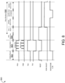
- the first polyfinger is controlled to integrate charge for a first exposure time
- the second polyfinger is controlled to integrate charge for a second exposure time, which may be non-overlapping with the first exposure time.
- each polyfinger may integrate charge for approximately 50% of the integration period. Then, for each pixel, the difference between the charge integrated at the first polyfinger and the charge integrated at the second polyfinger may be used to compute a depth value for the pixel.
- HDR images obtained via the depth sensor 102 may be used for display on an in-vehicle display system.
- the computing system may control the first polyfinger to integrate charge for a relatively longer exposure time and control the second polyfinger to integrate charge for a relatively shorter exposure time.
- the relatively longer exposure time may comprise 99-99.9% of the integration period, whereas the shorter exposure time may comprise 0.1-1% of the integration period.
- the computing system compares the charge collected at the first polyfinger and the charge collected at the second polyfinger to one or more thresholds (e.g. by converting the charges to digital signals via an analog-to-digital converter) to determine which charge to include in the two-dimensional image.
- the computing system stitches together selected data for all of the pixels to form an HDR image.
- the HDR image 200 generated in the use scenario 100 of FIG. 1 may be displayed via an interior display of the first automobile 104.
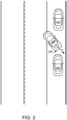
- FIG. 3 depicts an example use scenario 300 in which a first automobile 302 is backing into a parallel parking space between two parked automobiles 304 and 306.
- a depth image sensor 308 located at a rear of the first automobile 302 acquires, during a first set of integration periods, depth images of real-world surroundings, which are used to monitor a distance between the first automobile 302 and other objects (e.g. the parked vehicle 306).
- a first polyfinger and second polyfinger of each pixel of the depth image sensor 308 are controlled to collect long and short exposures, as described above.
- the depth image sensor 102 may switch an electrically controlled optical filter between passing infrared light for the first set of integration periods and visible light for the second set of integration periods.
- the two exposures for each pixel are then compared to one or more thresholds to determine which charge for each pixel to include in an HDR image, and the selected exposures for each pixel are stitched to other exposures to form the HDR image.
- the HDR image 400 of the surrounding environment may be output to a display, e.g. to provide visual feedback to a driver of the first automobile 302.
- a depth image sensor may be used to acquire HDR images in any other suitable context.
- a depth image sensor may be used as an eye of a robotic system.
- a robotic surgical system may perform depth sensing between a surgical instrument and an anatomical reference point for instrument tracking, and may utilize HDR imaging for displaying visible images to a surgeon.
- a depth image sensor may be integrated with a wearable device, such as a head-mounted display device, to perform depth sensing and present video feedthrough augmented reality (AR) imagery, among other possible uses.
- AR augmented reality
Landscapes
- Engineering & Computer Science (AREA)
- Multimedia (AREA)
- Signal Processing (AREA)
- Physics & Mathematics (AREA)
- General Physics & Mathematics (AREA)
- Computer Networks & Wireless Communication (AREA)
- Radar, Positioning & Navigation (AREA)
- Remote Sensing (AREA)
- Electromagnetism (AREA)
- Studio Devices (AREA)
- Image Processing (AREA)
- Optical Radar Systems And Details Thereof (AREA)
- Transforming Light Signals Into Electric Signals (AREA)
Claims (14)
- Verfahren zur Erzeugung eines Bildes mit hohem Dynamikbereich, HDR, über einen Tiefenbildsensor, der eine Anordnung von Pixeln umfasst, wobei jedes Pixel einen ersten Ladungssammelpunkt und einen zweiten Ladungssammelpunkt aufweist, wobei der erste Ladungssammelpunkt und der zweite Ladungssammelpunkt unabhängig voneinander steuerbar sind, um während einer Integrationsperiode Strom zu integrieren, wobei das Verfahren umfasst:während einer ersten Integrationsperiode Steuern des ersten Ladungssammelpunkts für eine erste Belichtungszeit;während der ersten Integrationsperiode Steuern des zweiten Ladungssammelpunkts für eine zweite Belichtungszeit, wobei die zweite Belichtungszeit kürzer ist als die erste Belichtungszeit; undfür jedes Pixel der Vielzahl von PixelnVergleichen einer am ersten Ladungssammelpunkt gesammelten Ladung und einer am zweiten Ladungssammelpunkt gesammelten Ladung mit einem Schwellenwert, undAuswählen der am ersten Ladungssammelpunkt gesammelten Ladung oder der am zweiten Ladungssammelpunkt gesammelten Ladung zur Aufnahme in das HDR-Bild auf der Grundlage des Vergleichs; undwährend einer zweiten Integrationsperiode Steuern des ersten Ladungssammelpunkts, um Ladung für eine dritte Belichtungszeit von 50 % der zweiten Integrationsperiode zu integrieren;während der zweiten Integrationsperiode Steuern des zweiten Ladungssammelpunkts, um Ladung für eine vierte Belichtungszeit von 50 % der zweiten Integrationsperiode zu integrieren; undfür jedes Pixel der Vielzahl von Pixeln Berechnen eines Tiefenwertes für das Pixel auf der Grundlage der während der dritten Belichtungszeit integrierten Ladung und der während der vierten Belichtungszeit integrierten Ladung, um ein Tiefenbild zu erzeugen.
- Verfahren nach Anspruch 1, wobei die erste Belichtungszeit 99-99,9 % der ersten Integrationsperiode umfasst und wobei die zweite Belichtungszeit 0,1-1 % der ersten Integrationsperiode umfasst.
- Verfahren nach Anspruch 1, wobei der erste Ladungssammelpunkt einen ersten Polyfinger umfasst und wobei der zweite Ladungssammelpunkt einen zweiten Polyfinger umfasst.
- Verfahren nach Anspruch 3, wobei Tiefenbilder und HDR-Bilder abwechselnd erzeugt werden.
- Verfahren nach Anspruch 3, wobei zwei oder mehr Tiefenbilder pro HDR-Bild erzeugt werden.
- Verfahren nach Anspruch 1, wobei der Schwellenwert innerhalb von 80-90 % eines Pixelsättigungswertes liegt.
- Verfahren nach Anspruch 1, wobei das Auswählen der am ersten Ladungssammelpunkt gesammelten Ladung oder der am zweiten Ladungssammelpunkt gesammelten Ladung zur Aufnahme in das HDR-Bild das Auswählen der am ersten Ladungssammelpunkt gesammelten Ladung umfasst, wenn die am ersten Ladungssammelpunkt gesammelte Ladung den Schwellenwert nicht überschreitet, und das Auswählen der am zweiten Ladungssammelpunkt gesammelten Ladung, wenn die am ersten Ladungssammelpunkt gesammelte Ladung den Schwellenwert überschreitet.
- Verfahren nach Anspruch 1, ferner umfassend das Löschen von Ladung aus schwebenden Diffusionsknoten, dem ersten Ladungssammelpunkt und dem zweiten Ladungssammelpunkt jedes Pixels am Ende der Integrationsperiode, um Blooming zu verhindern.
- Vorrichtung, umfassend:eine Anordnung von Pixeln, wobei jedes Pixel einen ersten Polyfinger und einen zweiten Polyfinger aufweist, wobei der erste Polyfinger und der zweite Polyfinger unabhängig voneinander steuerbar sind, um Ladung während einer Integrationsperiode zu integrieren;ein Logik-Subsystem; undein Speicher-Subsystem, das Anweisungen speichert, die vom Logik-Subsystem ausführbar sind zum:während einer ersten Integrationsperiode Steuern des ersten Polyfingers, um Ladung für eine erste Belichtungszeit zu integrieren;während der ersten Integrationsperiode Steuern des zweiten Polyfingers, um Ladung für eine zweite Belichtungszeit zu integrieren, wobei die zweite Belichtungszeit kürzer ist als die erste Belichtungszeit; undfür jedes Pixel der Vielzahl von PixelnVergleichen der am ersten Polyfinger integrierten Ladung und der am zweiten Polyfinger integrierten Ladung mit einem Schwellenwert, undbasierend auf dem Vergleich Auswählen einer der am ersten Polyfinger integrierten Ladung und der am zweiten Polyfinger integrierten Ladung zur Aufnahme in einem Bild mit hohem Dynamikbereich, HDR-Bild; undwährend einer zweiten Integrationsperiode Steuern des ersten Polyfingers, um Ladung für eine dritte Belichtungszeit von 50 % der zweiten Integrationsperiode zu integrieren;während der zweiten Integrationsperiode Steuern des zweiten Polyfingers, um Ladung für eine vierte Belichtungszeit von 50 % der zweiten Integrationsperiode zu integrieren; undfür jedes Pixel der Vielzahl von Pixeln Zuweisen eines Tiefenwertes zu dem Pixel auf der Grundlage der während der dritten Belichtungszeit integrierten Ladung und der während der vierten Belichtungszeit integrierten Ladung, um ein Tiefenbild zu erzeugen.
- Vorrichtung nach Anspruch 9, wobei die erste Belichtungszeit 99-99,9 % der ersten Integrationsperiode umfasst und wobei die zweite Belichtungszeit 0,1-1 % der ersten Integrationsperiode umfasst.
- Vorrichtung nach Anspruch 9, wobei die Anweisungen ausführbar sind, um abwechselnd Tiefenbilder und HDR-Bilder zu erzeugen.
- Vorrichtung nach Anspruch 9, wobei die Anweisungen ausführbar sind, um zwei oder mehr Tiefenbilder für jedes HDR-Bild zu erzeugen.
- Vorrichtung nach Anspruch 9, wobei der Schwellenwert einen Pixelsättigungswert umfasst.
- Vorrichtung nach Anspruch 9, wobei die Anweisungen ausführbar sind, um die am ersten Polyfinger gesammelte Ladung auszuwählen, wenn die am ersten Polyfinger gesammelte Ladung den Schwellenwert nicht überschreitet, und die am zweiten Polyfinger gesammelte Ladung auszuwählen, wenn die am ersten Polyfinger gesammelte Ladung den Schwellenwert überschreitet.
Applications Claiming Priority (2)
| Application Number | Priority Date | Filing Date | Title |
|---|---|---|---|
| US16/536,000 US11671720B2 (en) | 2019-08-08 | 2019-08-08 | HDR visible light imaging using TOF pixel |
| PCT/US2020/037345 WO2021025782A1 (en) | 2019-08-08 | 2020-06-12 | Hdr visible light imaging using tof pixel |
Publications (2)
| Publication Number | Publication Date |
|---|---|
| EP4011059A1 EP4011059A1 (de) | 2022-06-15 |
| EP4011059B1 true EP4011059B1 (de) | 2025-03-05 |
Family
ID=71452744
Family Applications (1)
| Application Number | Title | Priority Date | Filing Date |
|---|---|---|---|
| EP20736495.1A Active EP4011059B1 (de) | 2019-08-08 | 2020-06-12 | Hdr-bildgebung im sichtbaren licht mittels tof-pixel |
Country Status (5)
| Country | Link |
|---|---|
| US (1) | US11671720B2 (de) |
| EP (1) | EP4011059B1 (de) |
| JP (1) | JP7585302B2 (de) |
| KR (1) | KR102888593B1 (de) |
| WO (1) | WO2021025782A1 (de) |
Families Citing this family (7)
| Publication number | Priority date | Publication date | Assignee | Title |
|---|---|---|---|---|
| US11841438B2 (en) * | 2019-09-30 | 2023-12-12 | Zoox, Inc. | Power control of sensors using multiple exposures |
| US11726186B2 (en) * | 2019-09-30 | 2023-08-15 | Zoox, Inc. | Pixel filtering using multiple exposures |
| US20210356598A1 (en) * | 2020-05-15 | 2021-11-18 | Analog Devices International Unlimited Company | Camera system |
| CN112437213A (zh) * | 2020-10-28 | 2021-03-02 | 青岛小鸟看看科技有限公司 | 图像采集方法、手柄设备、头戴设备及头戴系统 |
| CN112527102B (zh) * | 2020-11-16 | 2022-11-08 | 青岛小鸟看看科技有限公司 | 头戴式一体机系统及其6DoF追踪方法和装置 |
| DE102021108054A1 (de) | 2021-03-30 | 2022-10-06 | Ifm Electronic Gmbh | Lichtlaufzeitkamera |
| US12002837B2 (en) * | 2021-06-25 | 2024-06-04 | Microsoft Technology Licensing, Llc | Imaging sensor with near-infrared absorber |
Family Cites Families (25)
| Publication number | Priority date | Publication date | Assignee | Title |
|---|---|---|---|---|
| US20060131484A1 (en) * | 2004-12-17 | 2006-06-22 | Mark Peting | High-dynamic range image sensors |
| WO2007119626A1 (ja) | 2006-03-31 | 2007-10-25 | National University Corporation Shizuoka University | 半導体測距素子及び固体撮像装置 |
| US8102435B2 (en) * | 2007-09-18 | 2012-01-24 | Stmicroelectronics S.R.L. | Method for acquiring a digital image with a large dynamic range with a sensor of lesser dynamic range |
| JP4893569B2 (ja) | 2007-09-28 | 2012-03-07 | ソニー株式会社 | 撮像装置、撮像制御方法及び撮像制御プログラム |
| US20090272881A1 (en) | 2008-05-05 | 2009-11-05 | Xiangli Li | Apparatus, method, and system providing pixel having increased fill factor |
| JP2010130343A (ja) * | 2008-11-27 | 2010-06-10 | Fujifilm Corp | 撮像装置及びその駆動制御方法 |
| US20100149379A1 (en) * | 2008-12-16 | 2010-06-17 | Summa Joseph R | Image sensor with three-dimensional interconnect and ccd |
| JP5365221B2 (ja) * | 2009-01-29 | 2013-12-11 | ソニー株式会社 | 固体撮像装置、その製造方法および撮像装置 |
| DE102009037596B4 (de) * | 2009-08-14 | 2014-07-24 | Fraunhofer-Gesellschaft zur Förderung der angewandten Forschung e.V. | Pixelstruktur, System und Verfahren zur optischen Abstandsmessung sowie Steuerschaltung für die Pixelstruktur |
| JP5655626B2 (ja) * | 2011-02-24 | 2015-01-21 | ソニー株式会社 | 画像処理装置、および画像処理方法、並びにプログラム |
| US8724002B2 (en) | 2011-02-28 | 2014-05-13 | Aptina Imaging Corporation | Imaging pixels with dummy transistors that reduce reset charge injection |
| JP2014139564A (ja) * | 2012-12-20 | 2014-07-31 | Sony Corp | 撮像装置および電子機器 |
| US9509919B2 (en) * | 2014-11-17 | 2016-11-29 | Duelight Llc | System and method for generating a digital image |
| JP2015207862A (ja) | 2014-04-18 | 2015-11-19 | コニカミノルタ株式会社 | 撮像装置および撮像方法 |
| EP2966856B1 (de) | 2014-07-08 | 2020-04-15 | Sony Depthsensing Solutions N.V. | Pixel mit hochdynamischem Bereich und Betriebsverfahren dafür |
| JP6525611B2 (ja) | 2015-01-29 | 2019-06-05 | キヤノン株式会社 | 画像処理装置およびその制御方法 |
| WO2016129410A1 (ja) | 2015-02-13 | 2016-08-18 | ソニー株式会社 | 撮像素子、駆動方法、および電子機器 |
| US9998692B1 (en) * | 2015-06-26 | 2018-06-12 | The United States Of America As Represented By The Secretary Of The Navy | Motion picture high dynamic range imaging |
| DE102015112398A1 (de) * | 2015-07-29 | 2017-02-02 | Infineon Technologies Ag | Bilderzeugungsvorrichtung und Bilderzeugungsverfahren zum Erfassen von Bilderzeugungsdaten über ein Pixelarray |
| CN107018338B (zh) * | 2016-01-22 | 2021-01-29 | 松下知识产权经营株式会社 | 摄像装置 |
| EP3211673B1 (de) | 2016-02-16 | 2020-11-04 | Espros Photonics AG | Hdr pixel |
| US10318831B2 (en) * | 2016-07-21 | 2019-06-11 | Gestigon Gmbh | Method and system for monitoring the status of the driver of a vehicle |
| US10389957B2 (en) * | 2016-12-20 | 2019-08-20 | Microsoft Technology Licensing, Llc | Readout voltage uncertainty compensation in time-of-flight imaging pixels |
| JP7027403B2 (ja) | 2017-02-28 | 2022-03-01 | ソニーセミコンダクタソリューションズ株式会社 | 測距装置、および測距方法 |
| US10892295B2 (en) * | 2018-01-10 | 2021-01-12 | Microsoft Technology Licensing, Llc | Germanium-modified, back-side illuminated optical sensor |
-
2019
- 2019-08-08 US US16/536,000 patent/US11671720B2/en active Active
-
2020
- 2020-06-12 WO PCT/US2020/037345 patent/WO2021025782A1/en not_active Ceased
- 2020-06-12 JP JP2022507604A patent/JP7585302B2/ja active Active
- 2020-06-12 KR KR1020227005794A patent/KR102888593B1/ko active Active
- 2020-06-12 EP EP20736495.1A patent/EP4011059B1/de active Active
Non-Patent Citations (1)
| Title |
|---|
| PAYNE ANDREW ET AL: "7.6 A 512x424 CMOS 3D Time-of-Flight image sensor with multi-frequency photo-demodulation up to 130MHz and 2GS/s ADC", IEEE INTERNATIONAL SOLID STATE CIRCUITS CONFERENCE, IEEE SERVICE CENTER, NEW YORK, NY, US, 9 February 2014 (2014-02-09), pages 134 - 135, XP032575106, ISSN: 0193-6530, ISBN: 978-1-4799-0918-6, [retrieved on 20140305], DOI: 10.1109/ISSCC.2014.6757370 * |
Also Published As
| Publication number | Publication date |
|---|---|
| KR20220036968A (ko) | 2022-03-23 |
| US11671720B2 (en) | 2023-06-06 |
| WO2021025782A1 (en) | 2021-02-11 |
| JP2022543459A (ja) | 2022-10-12 |
| US20210044767A1 (en) | 2021-02-11 |
| EP4011059A1 (de) | 2022-06-15 |
| KR102888593B1 (ko) | 2025-11-19 |
| JP7585302B2 (ja) | 2024-11-18 |
Similar Documents
| Publication | Publication Date | Title |
|---|---|---|
| EP4011059B1 (de) | Hdr-bildgebung im sichtbaren licht mittels tof-pixel | |
| US9182490B2 (en) | Video and 3D time-of-flight image sensors | |
| US11754718B2 (en) | Time of flight imaging using long and short-exposure storage nodes | |
| US9807369B2 (en) | 3D imaging apparatus | |
| CN107710742B (zh) | 固态成像元件、驱动方法和电子设备 | |
| US10607352B2 (en) | Reduced power operation of time-of-flight camera | |
| US11363188B2 (en) | Motion-based operation of imaging devices | |
| CN107110971A (zh) | 多模式深度成像 | |
| US11627274B2 (en) | Image sensing pixels with lateral overflow storage | |
| US20210360177A1 (en) | Global shutter time-of-flight camera | |
| KR20180125882A (ko) | 범위 측정을 위하여 ppd와 spad가 공유된 픽셀 및 시공간적인 상관관계를 이용하는 시간-분해 센서 | |
| EP4168825B1 (de) | Energiesparbetrieb von differenziellen time-of-flight-pixeln | |
| JP2009141813A (ja) | 撮像装置、カメラ、車両及び撮像方法 | |
| US10534240B2 (en) | Imaging control device, imaging control method, and recording medium having same recorded thereon | |
| US9851245B2 (en) | Accumulating charge from multiple imaging exposure periods | |
| US11742370B2 (en) | Time-of-flight pixel with vertical photogates | |
| CN114424522A (zh) | 图像处理装置、电子设备、图像处理方法与程序 | |
| US12470786B2 (en) | Image acquisition apparatus and electronic apparatus including same, and method of controlling image acquisition apparatus | |
| US20250301238A1 (en) | Combined imaging and depth module | |
| US20260032352A1 (en) | Image capturing apparatus and image capturing method |
Legal Events
| Date | Code | Title | Description |
|---|---|---|---|
| STAA | Information on the status of an ep patent application or granted ep patent |
Free format text: STATUS: UNKNOWN |
|
| STAA | Information on the status of an ep patent application or granted ep patent |
Free format text: STATUS: THE INTERNATIONAL PUBLICATION HAS BEEN MADE |
|
| PUAI | Public reference made under article 153(3) epc to a published international application that has entered the european phase |
Free format text: ORIGINAL CODE: 0009012 |
|
| STAA | Information on the status of an ep patent application or granted ep patent |
Free format text: STATUS: REQUEST FOR EXAMINATION WAS MADE |
|
| 17P | Request for examination filed |
Effective date: 20220125 |
|
| AK | Designated contracting states |
Kind code of ref document: A1 Designated state(s): AL AT BE BG CH CY CZ DE DK EE ES FI FR GB GR HR HU IE IS IT LI LT LU LV MC MK MT NL NO PL PT RO RS SE SI SK SM TR |
|
| DAV | Request for validation of the european patent (deleted) | ||
| DAX | Request for extension of the european patent (deleted) | ||
| REG | Reference to a national code |
Ref country code: DE Ref legal event code: R079 Free format text: PREVIOUS MAIN CLASS: H04N0005235000 Ipc: H04N0023741000 Ref document number: 602020047199 Country of ref document: DE |
|
| RIC1 | Information provided on ipc code assigned before grant |
Ipc: H04N 23/958 20230101ALI20240112BHEP Ipc: H04N 23/741 20230101AFI20240112BHEP |
|
| GRAP | Despatch of communication of intention to grant a patent |
Free format text: ORIGINAL CODE: EPIDOSNIGR1 |
|
| STAA | Information on the status of an ep patent application or granted ep patent |
Free format text: STATUS: GRANT OF PATENT IS INTENDED |
|
| INTG | Intention to grant announced |
Effective date: 20240301 |
|
| P01 | Opt-out of the competence of the unified patent court (upc) registered |
Effective date: 20240313 |
|
| GRAJ | Information related to disapproval of communication of intention to grant by the applicant or resumption of examination proceedings by the epo deleted |
Free format text: ORIGINAL CODE: EPIDOSDIGR1 |
|
| STAA | Information on the status of an ep patent application or granted ep patent |
Free format text: STATUS: REQUEST FOR EXAMINATION WAS MADE |
|
| INTC | Intention to grant announced (deleted) | ||
| GRAP | Despatch of communication of intention to grant a patent |
Free format text: ORIGINAL CODE: EPIDOSNIGR1 |
|
| STAA | Information on the status of an ep patent application or granted ep patent |
Free format text: STATUS: GRANT OF PATENT IS INTENDED |
|
| INTG | Intention to grant announced |
Effective date: 20240828 |
|
| GRAJ | Information related to disapproval of communication of intention to grant by the applicant or resumption of examination proceedings by the epo deleted |
Free format text: ORIGINAL CODE: EPIDOSDIGR1 |
|
| STAA | Information on the status of an ep patent application or granted ep patent |
Free format text: STATUS: REQUEST FOR EXAMINATION WAS MADE |
|
| GRAP | Despatch of communication of intention to grant a patent |
Free format text: ORIGINAL CODE: EPIDOSNIGR1 |
|
| STAA | Information on the status of an ep patent application or granted ep patent |
Free format text: STATUS: GRANT OF PATENT IS INTENDED |
|
| INTC | Intention to grant announced (deleted) | ||
| GRAS | Grant fee paid |
Free format text: ORIGINAL CODE: EPIDOSNIGR3 |
|
| INTG | Intention to grant announced |
Effective date: 20250103 |
|
| GRAA | (expected) grant |
Free format text: ORIGINAL CODE: 0009210 |
|
| STAA | Information on the status of an ep patent application or granted ep patent |
Free format text: STATUS: THE PATENT HAS BEEN GRANTED |
|
| AK | Designated contracting states |
Kind code of ref document: B1 Designated state(s): AL AT BE BG CH CY CZ DE DK EE ES FI FR GB GR HR HU IE IS IT LI LT LU LV MC MK MT NL NO PL PT RO RS SE SI SK SM TR |
|
| REG | Reference to a national code |
Ref country code: GB Ref legal event code: FG4D |
|
| REG | Reference to a national code |
Ref country code: CH Ref legal event code: EP |
|
| REG | Reference to a national code |
Ref country code: IE Ref legal event code: FG4D |
|
| REG | Reference to a national code |
Ref country code: DE Ref legal event code: R096 Ref document number: 602020047199 Country of ref document: DE |
|
| PG25 | Lapsed in a contracting state [announced via postgrant information from national office to epo] |
Ref country code: RS Free format text: LAPSE BECAUSE OF FAILURE TO SUBMIT A TRANSLATION OF THE DESCRIPTION OR TO PAY THE FEE WITHIN THE PRESCRIBED TIME-LIMIT Effective date: 20250605 |
|
| PG25 | Lapsed in a contracting state [announced via postgrant information from national office to epo] |
Ref country code: FI Free format text: LAPSE BECAUSE OF FAILURE TO SUBMIT A TRANSLATION OF THE DESCRIPTION OR TO PAY THE FEE WITHIN THE PRESCRIBED TIME-LIMIT Effective date: 20250305 |
|
| PGFP | Annual fee paid to national office [announced via postgrant information from national office to epo] |
Ref country code: DE Payment date: 20250520 Year of fee payment: 6 |
|
| REG | Reference to a national code |
Ref country code: NL Ref legal event code: MP Effective date: 20250305 |
|
| PG25 | Lapsed in a contracting state [announced via postgrant information from national office to epo] |
Ref country code: ES Free format text: LAPSE BECAUSE OF FAILURE TO SUBMIT A TRANSLATION OF THE DESCRIPTION OR TO PAY THE FEE WITHIN THE PRESCRIBED TIME-LIMIT Effective date: 20250305 |
|
| PGFP | Annual fee paid to national office [announced via postgrant information from national office to epo] |
Ref country code: GB Payment date: 20250520 Year of fee payment: 6 |
|
| REG | Reference to a national code |
Ref country code: LT Ref legal event code: MG9D |
|
| PG25 | Lapsed in a contracting state [announced via postgrant information from national office to epo] |
Ref country code: NO Free format text: LAPSE BECAUSE OF FAILURE TO SUBMIT A TRANSLATION OF THE DESCRIPTION OR TO PAY THE FEE WITHIN THE PRESCRIBED TIME-LIMIT Effective date: 20250605 |
|
| PG25 | Lapsed in a contracting state [announced via postgrant information from national office to epo] |
Ref country code: HR Free format text: LAPSE BECAUSE OF FAILURE TO SUBMIT A TRANSLATION OF THE DESCRIPTION OR TO PAY THE FEE WITHIN THE PRESCRIBED TIME-LIMIT Effective date: 20250305 |
|
| PG25 | Lapsed in a contracting state [announced via postgrant information from national office to epo] |
Ref country code: LV Free format text: LAPSE BECAUSE OF FAILURE TO SUBMIT A TRANSLATION OF THE DESCRIPTION OR TO PAY THE FEE WITHIN THE PRESCRIBED TIME-LIMIT Effective date: 20250305 |
|
| PG25 | Lapsed in a contracting state [announced via postgrant information from national office to epo] |
Ref country code: BG Free format text: LAPSE BECAUSE OF FAILURE TO SUBMIT A TRANSLATION OF THE DESCRIPTION OR TO PAY THE FEE WITHIN THE PRESCRIBED TIME-LIMIT Effective date: 20250305 Ref country code: GR Free format text: LAPSE BECAUSE OF FAILURE TO SUBMIT A TRANSLATION OF THE DESCRIPTION OR TO PAY THE FEE WITHIN THE PRESCRIBED TIME-LIMIT Effective date: 20250606 |
|
| REG | Reference to a national code |
Ref country code: AT Ref legal event code: MK05 Ref document number: 1774048 Country of ref document: AT Kind code of ref document: T Effective date: 20250305 |
|
| PG25 | Lapsed in a contracting state [announced via postgrant information from national office to epo] |
Ref country code: NL Free format text: LAPSE BECAUSE OF FAILURE TO SUBMIT A TRANSLATION OF THE DESCRIPTION OR TO PAY THE FEE WITHIN THE PRESCRIBED TIME-LIMIT Effective date: 20250305 |
|
| PG25 | Lapsed in a contracting state [announced via postgrant information from national office to epo] |
Ref country code: SE Free format text: LAPSE BECAUSE OF FAILURE TO SUBMIT A TRANSLATION OF THE DESCRIPTION OR TO PAY THE FEE WITHIN THE PRESCRIBED TIME-LIMIT Effective date: 20250305 |
|
| PG25 | Lapsed in a contracting state [announced via postgrant information from national office to epo] |
Ref country code: SM Free format text: LAPSE BECAUSE OF FAILURE TO SUBMIT A TRANSLATION OF THE DESCRIPTION OR TO PAY THE FEE WITHIN THE PRESCRIBED TIME-LIMIT Effective date: 20250305 |
|
| PG25 | Lapsed in a contracting state [announced via postgrant information from national office to epo] |
Ref country code: PT Free format text: LAPSE BECAUSE OF FAILURE TO SUBMIT A TRANSLATION OF THE DESCRIPTION OR TO PAY THE FEE WITHIN THE PRESCRIBED TIME-LIMIT Effective date: 20250707 |
|
| PG25 | Lapsed in a contracting state [announced via postgrant information from national office to epo] |
Ref country code: IT Free format text: LAPSE BECAUSE OF FAILURE TO SUBMIT A TRANSLATION OF THE DESCRIPTION OR TO PAY THE FEE WITHIN THE PRESCRIBED TIME-LIMIT Effective date: 20250305 Ref country code: PL Free format text: LAPSE BECAUSE OF FAILURE TO SUBMIT A TRANSLATION OF THE DESCRIPTION OR TO PAY THE FEE WITHIN THE PRESCRIBED TIME-LIMIT Effective date: 20250305 |
|
| PG25 | Lapsed in a contracting state [announced via postgrant information from national office to epo] |
Ref country code: AT Free format text: LAPSE BECAUSE OF FAILURE TO SUBMIT A TRANSLATION OF THE DESCRIPTION OR TO PAY THE FEE WITHIN THE PRESCRIBED TIME-LIMIT Effective date: 20250305 |
|
| PG25 | Lapsed in a contracting state [announced via postgrant information from national office to epo] |
Ref country code: CZ Free format text: LAPSE BECAUSE OF FAILURE TO SUBMIT A TRANSLATION OF THE DESCRIPTION OR TO PAY THE FEE WITHIN THE PRESCRIBED TIME-LIMIT Effective date: 20250305 Ref country code: EE Free format text: LAPSE BECAUSE OF FAILURE TO SUBMIT A TRANSLATION OF THE DESCRIPTION OR TO PAY THE FEE WITHIN THE PRESCRIBED TIME-LIMIT Effective date: 20250305 |
|
| PG25 | Lapsed in a contracting state [announced via postgrant information from national office to epo] |
Ref country code: RO Free format text: LAPSE BECAUSE OF FAILURE TO SUBMIT A TRANSLATION OF THE DESCRIPTION OR TO PAY THE FEE WITHIN THE PRESCRIBED TIME-LIMIT Effective date: 20250305 |
|
| PG25 | Lapsed in a contracting state [announced via postgrant information from national office to epo] |
Ref country code: SK Free format text: LAPSE BECAUSE OF FAILURE TO SUBMIT A TRANSLATION OF THE DESCRIPTION OR TO PAY THE FEE WITHIN THE PRESCRIBED TIME-LIMIT Effective date: 20250305 |
|
| PG25 | Lapsed in a contracting state [announced via postgrant information from national office to epo] |
Ref country code: IS Free format text: LAPSE BECAUSE OF FAILURE TO SUBMIT A TRANSLATION OF THE DESCRIPTION OR TO PAY THE FEE WITHIN THE PRESCRIBED TIME-LIMIT Effective date: 20250705 |
|
| REG | Reference to a national code |
Ref country code: DE Ref legal event code: R097 Ref document number: 602020047199 Country of ref document: DE |
|
| PLBE | No opposition filed within time limit |
Free format text: ORIGINAL CODE: 0009261 |
|
| STAA | Information on the status of an ep patent application or granted ep patent |
Free format text: STATUS: NO OPPOSITION FILED WITHIN TIME LIMIT |
|
| PG25 | Lapsed in a contracting state [announced via postgrant information from national office to epo] |
Ref country code: DK Free format text: LAPSE BECAUSE OF FAILURE TO SUBMIT A TRANSLATION OF THE DESCRIPTION OR TO PAY THE FEE WITHIN THE PRESCRIBED TIME-LIMIT Effective date: 20250305 |
|
| REG | Reference to a national code |
Ref country code: CH Ref legal event code: L10 Free format text: ST27 STATUS EVENT CODE: U-0-0-L10-L00 (AS PROVIDED BY THE NATIONAL OFFICE) Effective date: 20260114 |
|
| REG | Reference to a national code |
Ref country code: CH Ref legal event code: H13 Free format text: ST27 STATUS EVENT CODE: U-0-0-H10-H13 (AS PROVIDED BY THE NATIONAL OFFICE) Effective date: 20260127 |
|
| PG25 | Lapsed in a contracting state [announced via postgrant information from national office to epo] |
Ref country code: MC Free format text: LAPSE BECAUSE OF FAILURE TO SUBMIT A TRANSLATION OF THE DESCRIPTION OR TO PAY THE FEE WITHIN THE PRESCRIBED TIME-LIMIT Effective date: 20250305 |
|
| 26N | No opposition filed |
Effective date: 20251208 |
|
| PG25 | Lapsed in a contracting state [announced via postgrant information from national office to epo] |
Ref country code: LU Free format text: LAPSE BECAUSE OF NON-PAYMENT OF DUE FEES Effective date: 20250612 |
|
| REG | Reference to a national code |
Ref country code: BE Ref legal event code: MM Effective date: 20250630 |
|
| PG25 | Lapsed in a contracting state [announced via postgrant information from national office to epo] |
Ref country code: IE Free format text: LAPSE BECAUSE OF NON-PAYMENT OF DUE FEES Effective date: 20250612 |
|
| PG25 | Lapsed in a contracting state [announced via postgrant information from national office to epo] |
Ref country code: BE Free format text: LAPSE BECAUSE OF NON-PAYMENT OF DUE FEES Effective date: 20250630 |
|
| PG25 | Lapsed in a contracting state [announced via postgrant information from national office to epo] |
Ref country code: FR Free format text: LAPSE BECAUSE OF NON-PAYMENT OF DUE FEES Effective date: 20250630 |
|
| PG25 | Lapsed in a contracting state [announced via postgrant information from national office to epo] |
Ref country code: CH Free format text: LAPSE BECAUSE OF NON-PAYMENT OF DUE FEES Effective date: 20250630 |