EP4010671B1 - Verfahren und system zur quantifizierung der spektralen ähnlichkeit zwischen einer probenfarbe und einer zielfarbe - Google Patents
Verfahren und system zur quantifizierung der spektralen ähnlichkeit zwischen einer probenfarbe und einer zielfarbe Download PDFInfo
- Publication number
- EP4010671B1 EP4010671B1 EP20756787.6A EP20756787A EP4010671B1 EP 4010671 B1 EP4010671 B1 EP 4010671B1 EP 20756787 A EP20756787 A EP 20756787A EP 4010671 B1 EP4010671 B1 EP 4010671B1
- Authority
- EP
- European Patent Office
- Prior art keywords
- normalized
- coating
- values
- smp
- reflectance
- Prior art date
- Legal status (The legal status is an assumption and is not a legal conclusion. Google has not performed a legal analysis and makes no representation as to the accuracy of the status listed.)
- Active
Links
Images


Classifications
-
- G—PHYSICS
- G01—MEASURING; TESTING
- G01J—MEASUREMENT OF INTENSITY, VELOCITY, SPECTRAL CONTENT, POLARISATION, PHASE OR PULSE CHARACTERISTICS OF INFRARED, VISIBLE OR ULTRAVIOLET LIGHT; COLORIMETRY; RADIATION PYROMETRY
- G01J3/00—Spectrometry; Spectrophotometry; Monochromators; Measuring colours
- G01J3/46—Measurement of colour; Colour measuring devices, e.g. colorimeters
- G01J3/463—Colour matching
-
- G—PHYSICS
- G01—MEASURING; TESTING
- G01J—MEASUREMENT OF INTENSITY, VELOCITY, SPECTRAL CONTENT, POLARISATION, PHASE OR PULSE CHARACTERISTICS OF INFRARED, VISIBLE OR ULTRAVIOLET LIGHT; COLORIMETRY; RADIATION PYROMETRY
- G01J3/00—Spectrometry; Spectrophotometry; Monochromators; Measuring colours
- G01J3/46—Measurement of colour; Colour measuring devices, e.g. colorimeters
- G01J3/462—Computing operations in or between colour spaces; Colour management systems
-
- G—PHYSICS
- G01—MEASURING; TESTING
- G01J—MEASUREMENT OF INTENSITY, VELOCITY, SPECTRAL CONTENT, POLARISATION, PHASE OR PULSE CHARACTERISTICS OF INFRARED, VISIBLE OR ULTRAVIOLET LIGHT; COLORIMETRY; RADIATION PYROMETRY
- G01J3/00—Spectrometry; Spectrophotometry; Monochromators; Measuring colours
- G01J3/46—Measurement of colour; Colour measuring devices, e.g. colorimeters
- G01J3/50—Measurement of colour; Colour measuring devices, e.g. colorimeters using electric radiation detectors
- G01J3/504—Goniometric colour measurements, for example measurements of metallic or flake based paints
-
- G—PHYSICS
- G06—COMPUTING OR CALCULATING; COUNTING
- G06V—IMAGE OR VIDEO RECOGNITION OR UNDERSTANDING
- G06V10/00—Arrangements for image or video recognition or understanding
- G06V10/40—Extraction of image or video features
- G06V10/56—Extraction of image or video features relating to colour
-
- G—PHYSICS
- G06—COMPUTING OR CALCULATING; COUNTING
- G06V—IMAGE OR VIDEO RECOGNITION OR UNDERSTANDING
- G06V10/00—Arrangements for image or video recognition or understanding
- G06V10/40—Extraction of image or video features
- G06V10/60—Extraction of image or video features relating to illumination properties, e.g. using a reflectance or lighting model
-
- G—PHYSICS
- G01—MEASURING; TESTING
- G01N—INVESTIGATING OR ANALYSING MATERIALS BY DETERMINING THEIR CHEMICAL OR PHYSICAL PROPERTIES
- G01N21/00—Investigating or analysing materials by the use of optical means, i.e. using sub-millimetre waves, infrared, visible or ultraviolet light
Definitions
- the present disclosure refers to a method and a system for providing a match metric for quantifying a spectral similarity between at least one sample coating and a target coating.
- specifications of tinting bases are determined by using reference colors defined/expressed within the CIELab* color space (also known as CIE L*a*b* color space).
- the CIELab* color space is a color space defined by the International Commission on Illumination (CIE) in 1976 which expresses color as three values L*, a* and b*.
- CIE International Commission on Illumination
- the space is usually mapped onto a three-dimensional integer space for digital representation, and thus the L*, a* and b* values are usually absolute, with a pre-defined range.
- US 5 841 421 A discloses a method and system for selecting a previously used color match from a plurality of previously used color matches that best matches a color standard.
- Each of the plurality of previously used matches are identified with a spectral reflectance and a color formula.
- the plurality of previously used color matches are searched for a set of previous color matches that have a high probability of being adapted to attain the color spectrum and spectral reflectance of the color standard.
- a color match that provides the best match with the color of the standard is determined from the set of previous color matches.
- the formula of the best match is used to reproduce the color of the standard.
- the color formula of the best match is adapted until there is an acceptable match with the color of the standard.
- a formula with a small color difference dE* can not guarantee that a pigmentation, i.e. a pigment combination used in the target color can be exactly adjusted.
- a detailed characterization of tinting bases by means of a spectral analysis is needed.
- spectral curves are determined based on reflectance values measured at different wavelength values, e.g. in the range from 400 nm to 700 nm.
- spectral curves are captured for different measurement geometries, i.e. at different viewing angles and/or with different illumination angles.
- a mere visual look at such spectral curves is not sufficient to identify similarities and differences between the target color and the sample color.
- an identification of a pigmentation of a target color is time-consuming and costly so that the process is often reduced to a mere approximation of color coordinates within the CIELab* color space.
- sample coating a sample color
- target coating a target color
- a color matching and adjustment process is based on digital color measurements taken with a multi-angle spectrometer, e. g. a Byk-Mac ® I or a spectrometer of the XRite MA ® -T-family.
- Reflectance of a color coating is measured from several geometries (illumination and observation directions/angles).
- Typical measure geometries are a fixed illumination angle at 45° measured relative to the surface normal of the coating and viewing angles of -15°, 15°, 25°, 45°, 75°, 110°, each measured relative to the specular angle, i. e. the specular direction, the specular direction being defined as the outgoing direction that makes the same angle with the normal of the color coating surface as the incoming direction of the respective light ray. It is also possible to keep the viewing angle constant and to vary the illumination angle.
- a known basic structure of the color matching and adjustment process comprises the following steps:
- the present disclosure provides, according to claim 1, a computer-implemented method for providing a match metric for quantifying a similarity of spectral curves of a target coating and at least one sample coating.
- the method further comprises the step of: h) modifying an initial formulation of the sample coating so as to minimize the match metric for the similarity of the spectral curves between the target coating and the sample coating as constraint (beside the existing color difference metric(s)).
- the initial formulation of the sample coating is retrieved as one of one or more preliminary matching formulations from a database which comprises coating formulations and interrelated color characteristics such as L*, a*, b* values and optionally texture characteristics such as sparkle values or coarseness values. That means that starting from the target coating, it is first searched in the database for one or more preliminary matching formulations whose color and optionally texture data are equal or at least similar to those of the target coating, i. e. the color differences and optionally the texture differences between the one or more preliminary matching formulations and the target coating are minimal using a color and optionally texture matching algorithm.
- the initial formulation/formula of the sample coating can be pre-given or can be selected from a formulation database comprising formulations for coating compositions and interrelated appearance data.
- "Appearance” as used herein refers to the visual experience/perception by which a coating is viewed or recognized. Thus, appearance can include color, shape, texture, sparkle, glitter, gloss, transpareny, opacity and other visual effects of a coating, or a combination thereof.
- Modifying comprises admixing one or more components to the initial formula and/or omitting one or more components from the initial formula and/or changing a respective concentration/amount of one or more components of the initial formula, thus, obtaining a modified formula which better matches the target color regarding its appearance which can be expressed by different metrics, such as the color difference metric and the spectral similarity expressed by the match metric as disclosed herein.
- spectral similarity between the sample coating and the target coating is to be understood as similarity between a shape of the spectral (reflectance) curve of the sample coating and a shape of the spectral (reflectance) curve of the target coating.
- the proposed method provides a match metric in order to characterise a spectral similarity between two reflectance curves.
- a value of the match metric serves as a means to quantify a similarity between a pigmentation of a target coating and a pigmentation of a sample coating.
- all possible values of the match metric lie in a range of a scale that corresponds or is at least comparable to those scales which are used for other metrics used in a color matching process, such as the already mentioned color difference metric dE* defined in the CIELab* color space. Smaller values of the match metric represent a better spectral similarity and higher values of the match metric represent a worse spectral similarity between the two considered reflectance curves.
- a low spectral similarity metric indicates that the pigmentation of the formulation of the sample coating is not the same as the pigmentation which was used for the target coating. That means that the pigmentation of the sample coating is not optimal in order to match the target coating.
- a reflectance curve in the following also called spectral curve, describes in the scope of the present disclosure a reflectance behaviour of a coating at different wavelength values and at a specific measure geometry. For each measure geometry, a separate reflectance curve is to be determined, e.g. measured.
- the terms "measure geometry” and “measurement geometry” are used synonymously.
- sample coating designates a color, i.e. a paint layer that has been prepared according to a sample formula and coated on a surface.
- target coating designates a color, i.e. a paint layer coated on a surface whose underlying formula is unknown and which should to be replicated as best as possible.
- the spectral range lower than 420 nm can be excluded from analysis because of measurement uncertainty caused by additives in coatings like e. g. UV-blockers.
- the spectral range higher than 680 nm can be excluded from analysis because of limitations of paint layers regarding hiding power and resulting interferences with the substrate color.
- the proposed match metric allows to identify differences between a target coating and a sample coating, even if the color associated with the target coating and the color associated with the sample coating lie on the same point or on adjacent points in the CIELab* space. Thus, a non-optimal pigmentation with resulting metamerism effect can be considered and identified.
- the normalized spectral reflectance curve of the target coating is given/defined by the normalized reflectance values R ref , ⁇ i norm .
- the normalized spectral reflectance curve of the sample coating is given/defined by the normalized reflectance values R smp , ⁇ i norm .
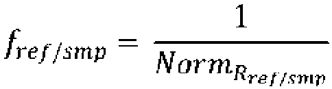
- the non-linear scaling function f ref,smp is referring to the luminance (L*) algorithm for the conversion of colors from the XYZ color space into the CIELab* color space.
- the L* metric is intended to mimic the logarithmic response for lightness of the human eye.
- the scaling function attempts to linearize the perceptibility of lightness.
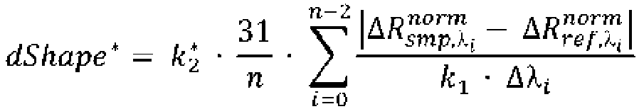
- the parameter k 1 and the parameters k 2 , k 2 ⁇ are freely selectable so as to define together (see formulas described above) the scale for the first match metric value dShape, dShape *.
- the proposed method provides a match metric that yields values in a scale, i.e. a scale space that is comparable to the scale space of the CIELab* color space and of color distance metrics which are defined in the CIELab* color space like e. g. the lightness difference metric dL* and the color difference metric dE*.
- a match metric that yields values in a scale
- a scale space that is comparable to the scale space of the CIELab* color space and of color distance metrics which are defined in the CIELab* color space like e. g. the lightness difference metric dL* and the color difference metric dE*.
- a formula retrieved from a database whose color difference dE*, optionally also whose texture difference, whose sparkle difference dS and whose graininess difference dG, and whose newly calculated match metric dShape are minimal when all metrics are considered separately, i.e. on its own.
- a further correction / modification of the best matching formula is performed using a cost function which combines all those considered metrics, e. g. by adding all considered metrics together: dE* (or dL* + da* + db*) + dShape (optionally: + dS + dG + ...), probably each summand being weighted appropriately, and minimizing such cost function accordingly.
- the at least one measurement geometry is chosen from the group comprising -15°, 15°, 25, 45°, 75° and 110°, each measured relative to the specular angle.
- the characteristic information about the pigmentation in paint i.e. in the target coating and the sample coating, respectively, is included in a respective shape of the measured spectral curves, particularly of the measured reflectance curves.
- the terms "spectral curve”, “spectral reflectance curve” and “reflectance curve” are used synonymously.
- Pigments have typical absorption and scattering characteristics which produce characteristic fingerprints in the spectral curves.
- the absolute intensities of the reflectance values are less important than the shape of the reflectance/spectral curve, which can be encoded by the first derivate values of the normalized spectral curve.
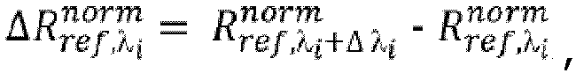
- a useful metric is the difference, i.e. the difference values, between the normalized first derivate (values) of the respective normalized spectral curves of the target coating and the sample coating.
- This match metric includes information about the shape of the spectral curves and it does not include information about the absolute intensity of the reflectance values.
- the strategy to use the normalized first derivate (values) of respective normalized spectral curves as match metric can also be combined, as mentioned above, with other metrics in the field of color searching, matching and adjustment, e. g. with color difference metric and optionally texture difference metric.
- the present disclosure further refers to a system for providing a match metric for quantifiying a similarity of spectral curves of a target coating and at least one sample coating with the features of claim 7.
- system further comprises:
- the color measuring device is a spectrometer, particularly a multi-angle spectrometer, such as a Byk-Mac ® I or a spectrometer of the XRite-MA ® -T-family.
- the output device can also be a component of the system.
- the computing process further comprises a color retrieval process for matching the color of the target coating and the at least one sample coating
- the matching process comprises at least the steps of:
- the computing process further comprises the step of B10) modifying an initial formula, particularly the selected at least one preliminary matching formula, for the sample coating so as to minimize the match metric beside other colorimetric metrics like color differences and optionally texture differences.
- the color measuring device, the computing device and the formulation database are networked among each other via respective communicative connections.
- Each of the communicative connections between the different components of the system may be a direct connection or an indirect connection, respectively.
- Each communicative connection may be a wired or a wireless connection.
- Each suitable communication technology may be used.
- the formulation database, the color measuring device, the computing device each may include one or more communications interfaces for communicating with each other. Such communication may be executed using a wired data transmission protocol, such as fiber distributed data interface (FDDI), digital subscriber line (DSL), Ethernet, asynchronous transfer mode (ATM), or any other wired transmission protocol.
- FDDI fiber distributed data interface
- DSL digital subscriber line
- ATM asynchronous transfer mode
- the communication may be wirelessly via wireless communication networks using any of a variety of protocols, such as General Packet Radio Service (GPRS), Universal Mobile Telecommunications System (UMTS), Code Division Multiple Access (CDMA), Long Term Evolution (LTE), wireless Universal Serial Bus (USB), and/or any other wireless protocol.
- GPRS General Packet Radio Service
- UMTS Universal Mobile Telecommunications System
- CDMA Code Division Multiple Access
- LTE Long Term Evolution
- USB wireless Universal Serial Bus
- the respective communication may be a combination of a wireless and a wired communication.
- the computing device may include or may be in communication with one or more input devices, such as a touch screen, an audio input, a movement input, a mouse, a keypad input and/or the like. Further the computing device may include or may be in communication with one or more output devices, such as an audio output, a video output, screen/display output, and/or the like.
- input devices such as a touch screen, an audio input, a movement input, a mouse, a keypad input and/or the like.
- output devices such as an audio output, a video output, screen/display output, and/or the like.
- Embodiments of the invention may be used with or incorporated in a computer system that may be a standalone unit or include one or more remote terminals or devices in communication with a central computer, located, for example, in a cloud, via a network such as, for example, the Internet or an intranet.
- a central computer located, for example, in a cloud
- a network such as, for example, the Internet or an intranet.
- the computing device described herein and related components may be a portion of a local computer system or a remote computer or an online system or a combination thereof.
- the formulation database and software described herein may be stored in computer internal memory or in a non-transitory computer readable medium.
- the database may be part of the data storage unit or may represent the data storage unit itself.
- the terms “database” and “data storage unit” are used synonymously.
- the present disclosure describes the match metric as a metric that can be combined with other metrics in the field of color searching, matching and adjusting, such as, for example, color differences, sparkle differences, flop differences, etc.
- the interpretation of the match metric is facilitated in the overview with the other metrics as the value ranges of all such different metrics lie in a comparable scale space.
- the proposed method and system enables a better converging of a color matching and adjustment process. Further an effort needed in a respective laboratory can be reduced for color development and for customer service matching. The color matching process as a whole is more reliable and faster.
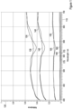
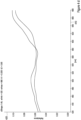
- Figure 1 shows normalized spectral measurements, i.e. normalized spectral reflectance curves of a target coating and a sample coating at different viewing angles.
- the in-plane bidirectional reflectance of a metallic pigmented sample coating was measured using a multi-angle spectrometer, e. g. a Byk-Mac ® I or a spectrometer of the XRite MA ® -T-family. Reflectance of the sample coating is measured from several geometries, namely with a given illumination angle of 45° measured relative to the surface normal of the coating and viewing angles of -15°, 15°, 25°, 45°, 75°, 110°, each measured relative to the specular angle.
- the wavelength of an incident light flux is plotted along a horizontal axis 110.
- the normalized reflectance of the sample coating and of the target coating is plotted along a vertical axis 120.
- the curve 130 indicates the reflectance of the target coating measured at a viewing angle of -15°
- the curve 135 indicates the reflectance of the sample coating measured at the viewing angle of -15°
- the curve 140 indicates the reflectance of the target coating and the curve 145 indicates the reflectance of the sample coating measured at a viewing angle of 15°, respectively.
- the curve 150 indicates the reflectance of the target coating and the curve 155 indicates the reflectance of the sample coating measured at a viewing angle of 25°, respectively.
- the curve 160 indicates the reflectance of the target coating and the curve 165 indicates the reflectance of the sample coating measured at a viewing angle of 45°, respectively.
- the curve 170 indicates the reflectance of the target coating and the curve 175 indicates the sample coating measured at a viewing angle of 75°, respectively.
- the reflectance curve of the target coating and the reflectance curve of the sample coating measured at a viewing angle of 110°, respectively, can not be differentiated in the representation here from the reflectance curves 170, 175, respectively, as at the flop angles 45°, 75° and 110°, only small reflectance values are measured, respectively. Further, only small variances of shape of the respective curves dependent on the wavelength are observed.
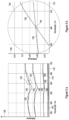
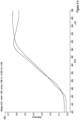
- Figure 2 shows a diagram of the spectral reflectance curves of the target coating of Figure 1 and, for each spectral reflectance curve, an average reflectance value 131, 141, 151, 161, 171 of the target coating, each indicated as dashed line.
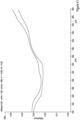
- Figure 3a shows the diagram of the normalized spectral reflectance curves of Figure 1 wherein a specific region 133 is encircled.
- Figure 3b shows the encircled region 133 of Figure 3a in an enlarged representation.
- the crossing point 134 of the two reflectance curves 130 and 135 is considered in the following.
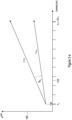
- a difference value between the normalized first derivative value of the reflectance curve of the target coating and the normalized first derivative value of the reflectance curve of the sample coating can be indicated as an angle ⁇ ⁇ i (see Figure 3e ).
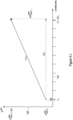
- Figure 3d shows a normalized vector indicating a gradient of the reflectance curve of the sample coating in the encircled region of Figure 3b , particularly at the crossing point 134.
- the enlarged section of the horizontal axis 110' is shown which reaches from ⁇ i ⁇ 605,3 nm to ⁇ i + ⁇ i .
- an enlarged section 120' of the vertical axis 120 is shown which embraces reflectance values from R smp , ⁇ i norm to R smp , ⁇ i + ⁇ ⁇ i norm .
- R smp , ⁇ i norm indicates a normalized reflectance value of the sample coating at the wavelength value ⁇ i
- k 1 is the non-linear damping parameter.
- ⁇ ⁇ i indicates the angle between the two normalized vectors u ⁇ i and v ⁇ i , the vector u ⁇ i indicating a gradient of the reflectance curve of the target coating at ⁇ i and the vector v ⁇ i indicating a gradient of the reflectance curve of the sample coating at ⁇ i .
- Figure 4 shows in the Figures 4a to 4k examples of values of the match metric dShape as provided by an embodiment of the proposed method.
- Figures 4a to 4k each show a diagram of a normalized spectral curve of a target coating and a normalized spectral curve of a sample coating.
- the wavelength values are plotted along a horizontal axis 410 and are chosen from an interval from a minimum wavelength value to a maximum wavelength value, with the minimum wavelength value being 420 nm and the maximum wavelength value being 680 nm.
- the normalized reflectance values of the target coating and the sample coating, respectively, are plotted along a vertical axis 420 which ranges from 0,0 to 0,5.
- FIG. 5 schematically illustrates an embodiment of the proposed system.
- the system 500 shown here comprises a computing device 510, a formulation database 520, a color measurement device 530, an output device 540, an input device 550 and a computer readable storage medium 560.
- the system further comprises a computer program product which comprises computer executable codes stored on the computer readable storage medium 560.
- the computer readable storage medium 560 is loaded in an internal memory of the computing device 510.
- the computer readable storage medium 560 is functionally coupled to the computing device 510. Any other functional coupling of the computer readable storage medium 560 and the computing device 510 is possible.
- the computer readable storage medium 560 causes the computing device 510 to perform a computing process when in operation, the computing process comprises the steps of:
- the formulation database 520 comprises formulas for coating compositions and interrelated colorimetric data and is functionally coupled to the computing device 510.
- the color measuring device 530 which is also functionally coupled to the computing device 510, is a spectrometer, particularly a multi-angle spectrometer, such as a Byk-Mac ® I or a spectrometer of the XRite-MA ® -T-family.
- the computing process may further comprise a color retrieval process for matching the color of the target coating and the at least one sample coating, the matching process comprises at least the steps of:
- the computing process may further comprise the step of B10) modifying an initial formula, particularly the selected at least one preliminary matching formula, for the sample coating so as to minimize the match metric beside other colorimetric metrics like color differences and optionally texture differences.
- the color measuring device 530, the computing device 510 and the formulation database 520 are networked among each other via respective communicative connections.
- the input device 550 and the output device 540 are part of the computing device 510 or at least functionally coupled with the computing device 510. It is possible to illustrate on the output device 540 simultaneously, both, the target coating, i.e. the spectral curve of the target coating, and the sample coating, i.e. the spectral curve of the sample coating, so as to allow a visual comparision "on the fly", i.e. during operation of the matching process.
Landscapes
- Physics & Mathematics (AREA)
- Spectroscopy & Molecular Physics (AREA)
- General Physics & Mathematics (AREA)
- Engineering & Computer Science (AREA)
- Theoretical Computer Science (AREA)
- Mathematical Physics (AREA)
- Multimedia (AREA)
- Software Systems (AREA)
- Spectrometry And Color Measurement (AREA)
- Investigating Or Analysing Materials By Optical Means (AREA)
Claims (10)
- Computerimplementiertes Verfahren zum Bereitstellen einer Abgleichungsmetrik zum Quantifizieren einer spektralen Ähnlichkeit zwischen einer Zielbeschichtung und mindestens einer Probenbeschichtung, wobei das Verfahren mindestens die folgenden Schritte umfasst:a) Erhalten, für eine Anzahl von Wellenlängenwerten, von Reflexionsgraden der Zielbeschichtung und von Reflexionsgraden der Probenbeschichtung, wobei die Reflexionsgrade der Zielbeschichtung mit einer oder mehreren Messgeometrien ermittelt werden, und wobei die Reflexionsgrade der Probenbeschichtung mit der einen oder den mehreren Messgeometrien ermittelt werden; undunter Verwendung von einem oder mehreren Prozessoren:b) Normalisieren von jedem der Reflexionsgrade der Zielbeschichtung, die mit der entsprechenden der einen oder mehreren Messgeometrien ermittelt werden, und der Reflexionsgrade der Probenbeschichtung, die mit der entsprechenden der einen oder mehreren Messgeometrien ermittelt werden, indem eine Skalierungsfunktion verwendet wird;c) Erzeugen einer normalisierten Reflexionskurve für die Zielbeschichtung basierend auf den normalisierten Reflexionsgraden der Zielbeschichtung für jeden Wellenlängenwert und einer normalisierten Reflexionskurve für die Probenbeschichtung basierend auf den normalisierten Reflexionsgraden der Probenbeschichtung für jeden Wellenlängenwert;d) Produzieren, für die Anzahl von Wellenlängenwerten, von normalisierten ersten Ableitungswerten der normalisierten Reflexionskurve der Zielbeschichtung in Bezug auf die Wellenlänge und von normalisierten ersten Ableitungswerten der normalisierten Reflexionskurve der Probenbeschichtung in Bezug auf die Wellenlänge;e) Produzieren, für jeden Wellenlängenwert aus der Anzahl von Wellenlängenwerten, von Differenzwerten zwischen den normalisierten ersten Ableitungswerten der normalisierten Reflexionskurve der Zielbeschichtung und den normalisierten ersten Ableitungswerten der normalisierten Reflexionskurve der Probenbeschichtung;f) Produzieren einer Abgleichungsmetrik für eine Ähnlichkeit zwischen den normalisierten Reflexionskurven der Zielbeschichtung und der Probenbeschichtung mindestens teilweise basierend auf den Differenzwerten für alle aus der Anzahl von Wellenlängenwerten,g) Ausgeben, unter Verwendung einer Ausgabevorrichtung, der produzierten Abgleichungsmetrik für einen Benutzer, wobei Schritt d) ferner umfasst: d2) Transformieren der normalisierten ersten Ableitungswerte der normalisierten Reflexionskurve der Zielbeschichtung bzw. der normalisierten ersten Ableitungswerte der normalisierten Reflexionskurve der Probenbeschichtung, in Bezug auf die Wellenlänge, in eine Winkeldarstellung, wobei die ersten normalisierten Ableitungswerte der normalisierten Reflexionskurve der Zielbeschichtung bzw. die ersten normalisierten Ableitungswerte der normalisierten Reflexionskurve der Probenbeschichtung für jeden Wellenlängenwert als ein zweidimensionaler Vektor gemäß den folgenden Formeln dargestellt werden:


- Verfahren nach Anspruch 1, wobei das Verfahren ferner den folgenden Schritt umfasst:
h) Abrufen, aus einer Formulierungsdatenbank, die Formeln für Beschichtungszusammensetzungen und miteinander verbundene colorimetrische Eigenschaften umfasst, einer oder mehrerer vorläufiger Abgleichungsformeln basierend auf Reflexionsgraden der Probenbeschichtung und/oder von weiteren vorbestimmten Farbeigenschaften der Probenbeschichtung oder einer Kombination davon. - Verfahren nach Anspruch 1 oder 2, wobei das Verfahren ferner den folgenden Schritt umfasst:i) Modifizieren einer anfänglichen Formulierung der Probenbeschichtung, insbesondere einer der einen oder mehreren vorläufigen Abgleichungsformeln, die aus der Datenbank nach Anspruch 2 abgerufen werden, um die Abgleichungsmetrik für die Ähnlichkeit der normalisierten Reflexionskurven der Zielbeschichtung und der Probenbeschichtung als zusätzliche Einschränkung neben der bestehenden Farbdifferenzmetrik (den bestehenden Farbdifferenzmetriken) zu minimieren.
- Verfahren nach einem der vorhergehenden Ansprüche, wobei die Skalierungsfunktion gewählt wird als eine nicht-lineare Skalierungsfunktion fref,smp die wie folgt gewählt wird:


- Verfahren nach einem der vorhergehenden Ansprüche, wobei die Abgleichungsmetrik wie folgt gewählt wird:

- Verfahren nach einem der vorhergehenden Ansprüche, wobei die Abgleichungsmetrik wie folgt gewählt wird:


- System (500) zum Bereitstellen einer Abgleichungsmetrik zum Quantifizieren einer spektralen Ähnlichkeit einer Zielbeschichtung und mindestens einer Probenbeschichtung, wobei das System umfasst:A) eine Rechenvorrichtung (510);B) ein Computerprogrammprodukt, wobei das Computerprogrammprodukt computerausführbare Codes umfasst, die in einem computerlesbaren Speichermedium (560) gespeichert sind, das funktionsfähig mit der Rechenvorrichtung (510) gekoppelt ist und veranlasst, dass die Rechenvorrichtung (510) im Betrieb einen Rechenprozess durchführt, wobei der Rechenprozess die folgenden Schritte umfasst:B1) Empfangen, für eine Anzahl von Wellenlängenwerten, von Reflexionsgraden der Zielbeschichtung und von Reflexionsgraden der Probenbeschichtung, wobei die Reflexionsgrade der Zielbeschichtung mit einer oder mehreren Messgeometrien ermittelt werden, und die Reflexionsgrade der Probenbeschichtung mit der einen oder den mehreren Messgeometrien ermittelt werden;B2) Normalisieren von jedem der Reflexionsgrade der Zielbeschichtung, die mit der entsprechenden der einen oder mehreren Messgeometrien ermittelt werden, und der Reflexionsgrade der Probenbeschichtung, die mit der entsprechenden der einen oder mehreren Messgeometrien ermittelt werden, indem eine nicht-lineare Skalierungsfunktion verwendet wird;B3) Erzeugen einer normalisierten Reflexionskurve für die Zielbeschichtung basierend auf den normalisierten Reflexionsgraden der Zielbeschichtung für jeden Wellenlängenwert und einer normalisierten Reflexionskurve für die Probenbeschichtung basierend auf den normalisierten Reflexionsgraden der Probenbeschichtung für jeden Wellenlängenwert;B4) Produzieren, für die Anzahl von Wellenlängenwerten, von normalisierten ersten Ableitungswerten der normalisierten Reflexionskurve der Zielbeschichtung in Bezug auf die Wellenlänge und von normalisierten ersten Ableitungswerten der normalisierten Reflexionskurve der Probenbeschichtung in Bezug auf die Wellenlänge;B5) Produzieren, für jeden Wellenlängenwert aus der Anzahl von Wellenlängenwerten, von Differenzwerten zwischen den normalisierten ersten Ableitungswerten der normalisierten Reflexionskurve der Zielbeschichtung und den normalisierten ersten Ableitungswerten der normalisierten Reflexionskurve der Probenbeschichtung;B6) Produzieren einer Abgleichungsmetrik für eine Ähnlichkeit zwischen den normalisierten Reflexionskurven der Zielbeschichtung und der Probenbeschichtung mindestens teilweise basierend auf den Differenzwerten für alle aus der Anzahl von Wellenlängenwerten wobei der Schritt B4) ferner umfasst: B4_2) Transformieren der normalisierten ersten Ableitungswerte der normalisierten Reflexionskurve der Zielbeschichtung bzw. der normalisierten ersten Ableitungswerte der normalisierten Reflexionskurve der Probenbeschichtung, in Bezug auf die Wellenlänge, in eine Winkeldarstellung; wobei die ersten normalisierten Ableitungswerte der normalisierten Reflexionskurve der Zielbeschichtung bzw. die ersten normalisierten Ableitungswerte der normalisierten Reflexionskurve der Probenbeschichtung für jeden Wellenlängenwert als ein zweidimensionaler Vektor gemäß den folgenden Formeln dargestellt werden:


- System nach Anspruch 7, das ferner umfasst:C) eine Farbmessvorrichtung (530);D) eine Formulierungsdatenbank (520), die Formeln für Beschichtungszusammensetzungen und miteinander verbundene colorimetrische Daten umfasst;wobei die Rechenvorrichtung (510) funktionsfähig mit der Farbmessvorrichtung (530) und der Formulierungsdatenbank (520) gekoppelt ist.
- System nach einem der Ansprüche 7 oder 8,
wobei der Rechenprozess ferner einen Abgleichungsprozess zum Abgleichen der Farbe der Zielbeschichtung und der mindestens einen Probenbeschichtung umfasst, wobei der Abgleichungsprozess mindestens einen der folgenden Schritte umfasst:B7) Abrufen aus der Formulierungsdatenbank (520) einer oder mehrerer vorläufiger Abgleichungsformeln basierend auf den colorimetrischen Probendaten;B8) Auswählen mindestens einer aus den vorläufigen Abgleichungsformeln, um die Abgleichungsmetrik neben anderen colorimetrischen Metriken zu minimieren. - Verfahren nach einem der Ansprüche 7 bis 9,
wobei der Rechenprozess ferner den Schritt umfasst eines B9) Modifizierens einer Formel für die Probenbeschichtung, um die Abgleichungsmetrik neben anderen colorimetrischen Metriken zu minimieren.
Applications Claiming Priority (2)
| Application Number | Priority Date | Filing Date | Title |
|---|---|---|---|
| EP19190388 | 2019-08-06 | ||
| PCT/EP2020/071750 WO2021023684A1 (en) | 2019-08-06 | 2020-08-01 | Method and system for quantifying a spectral similarity between a sample color and a target color |
Publications (3)
| Publication Number | Publication Date |
|---|---|
| EP4010671A1 EP4010671A1 (de) | 2022-06-15 |
| EP4010671C0 EP4010671C0 (de) | 2025-06-04 |
| EP4010671B1 true EP4010671B1 (de) | 2025-06-04 |
Family
ID=67551215
Family Applications (1)
| Application Number | Title | Priority Date | Filing Date |
|---|---|---|---|
| EP20756787.6A Active EP4010671B1 (de) | 2019-08-06 | 2020-08-01 | Verfahren und system zur quantifizierung der spektralen ähnlichkeit zwischen einer probenfarbe und einer zielfarbe |
Country Status (8)
| Country | Link |
|---|---|
| US (1) | US12140479B2 (de) |
| EP (1) | EP4010671B1 (de) |
| JP (1) | JP7383793B2 (de) |
| CN (1) | CN114174784B (de) |
| AU (1) | AU2020326153B2 (de) |
| CA (1) | CA3143773A1 (de) |
| MX (1) | MX2022001503A (de) |
| WO (1) | WO2021023684A1 (de) |
Families Citing this family (3)
| Publication number | Priority date | Publication date | Assignee | Title |
|---|---|---|---|---|
| CN114581537B (zh) * | 2022-03-02 | 2025-01-07 | 红塔烟草(集团)有限责任公司 | 一种初烤烟颜色的识别方法 |
| CN115078301B (zh) * | 2022-06-30 | 2025-03-18 | 上海中医药大学 | 一种利用太赫兹频域光谱快速鉴别林下山参和园参的方法 |
| JP2025005233A (ja) * | 2023-06-27 | 2025-01-16 | キヤノン株式会社 | 画像処理装置、制御方法、プログラムおよびカラーチャート |
Family Cites Families (6)
| Publication number | Priority date | Publication date | Assignee | Title |
|---|---|---|---|---|
| US5841421A (en) * | 1995-12-18 | 1998-11-24 | General Electric Company | Method and system for selecting a previous color match from a set of previous color matches that best matches a color standard |
| US6342952B1 (en) | 1999-10-11 | 2002-01-29 | Flint Ink Corporation | Method for matching printing ink colors |
| US6772151B1 (en) | 2000-06-16 | 2004-08-03 | Polyone Corporation | Color matching system and method |
| US6870614B2 (en) | 2002-05-30 | 2005-03-22 | General Electric Company | Method, system and computer product for formulating a bi-directional color match |
| US8692991B2 (en) * | 2012-02-03 | 2014-04-08 | Ppg Industries Ohio, Inc. | Optimal tint identifier/selector |
| US9734590B2 (en) * | 2013-02-26 | 2017-08-15 | Axalta Coating Systems Ip Co., Llc | Process for matching color and appearance of coatings |
-
2020
- 2020-08-01 CN CN202080054760.4A patent/CN114174784B/zh active Active
- 2020-08-01 JP JP2022507626A patent/JP7383793B2/ja active Active
- 2020-08-01 EP EP20756787.6A patent/EP4010671B1/de active Active
- 2020-08-01 AU AU2020326153A patent/AU2020326153B2/en active Active
- 2020-08-01 US US17/632,801 patent/US12140479B2/en active Active
- 2020-08-01 WO PCT/EP2020/071750 patent/WO2021023684A1/en not_active Ceased
- 2020-08-01 CA CA3143773A patent/CA3143773A1/en active Pending
- 2020-08-01 MX MX2022001503A patent/MX2022001503A/es unknown
Also Published As
| Publication number | Publication date |
|---|---|
| EP4010671A1 (de) | 2022-06-15 |
| US12140479B2 (en) | 2024-11-12 |
| AU2020326153A1 (en) | 2022-02-24 |
| JP2022543846A (ja) | 2022-10-14 |
| CN114174784B (zh) | 2025-09-12 |
| EP4010671C0 (de) | 2025-06-04 |
| MX2022001503A (es) | 2022-03-17 |
| AU2020326153B2 (en) | 2025-07-31 |
| WO2021023684A1 (en) | 2021-02-11 |
| CA3143773A1 (en) | 2021-02-11 |
| CN114174784A (zh) | 2022-03-11 |
| US20220283031A1 (en) | 2022-09-08 |
| JP7383793B2 (ja) | 2023-11-20 |
Similar Documents
| Publication | Publication Date | Title |
|---|---|---|
| JP4623842B2 (ja) | メタリック塗色の近似色を高速に検索する方法 | |
| EP4010671B1 (de) | Verfahren und system zur quantifizierung der spektralen ähnlichkeit zwischen einer probenfarbe und einer zielfarbe | |
| US12038328B2 (en) | Generation of a bi-directional texture function | |
| JP3671088B2 (ja) | メタリツク塗膜の光学的性質を決定する方法 | |
| CN113189021A (zh) | 基于光谱识别岩石颜色的方法 | |
| JPH11269411A (ja) | コンピュータグラフィックス画像から塗料配合を推定する方法 | |
| US20220366581A1 (en) | Generation of a Formulation for a Coating Which Matches the Optical Properties of a Target Coating Comprising Effect Pigments | |
| EP4010669B1 (de) | Verfahren und system zum abgleichen und abstimmen der pigmentierung einer probenbeschichtung mit einer zielbeschichtung | |
| EP4010670B1 (de) | Verfahren und system für robusten farbabgleich- und abstimmungsprozess von effektfarben | |
| JPWO2021023684A5 (de) | ||
| CA3146286C (en) | Method and system for a robust color matching and adjustment process of effect colors | |
| EP4097682A1 (de) | System und verfahren zur beurteilung des farbtones und der anwendung eines lippenstiftes | |
| JP2003034762A (ja) | 光輝感を有する塗料の調色方法 | |
| JP2025505472A (ja) | 反射性基材にデジタル印刷するためのインクの投入 | |
| Fiorentin et al. | Performance analysis of an imaging spectro-chroma meter |
Legal Events
| Date | Code | Title | Description |
|---|---|---|---|
| STAA | Information on the status of an ep patent application or granted ep patent |
Free format text: STATUS: UNKNOWN |
|
| STAA | Information on the status of an ep patent application or granted ep patent |
Free format text: STATUS: THE INTERNATIONAL PUBLICATION HAS BEEN MADE |
|
| PUAI | Public reference made under article 153(3) epc to a published international application that has entered the european phase |
Free format text: ORIGINAL CODE: 0009012 |
|
| STAA | Information on the status of an ep patent application or granted ep patent |
Free format text: STATUS: REQUEST FOR EXAMINATION WAS MADE |
|
| 17P | Request for examination filed |
Effective date: 20220307 |
|
| AK | Designated contracting states |
Kind code of ref document: A1 Designated state(s): AL AT BE BG CH CY CZ DE DK EE ES FI FR GB GR HR HU IE IS IT LI LT LU LV MC MK MT NL NO PL PT RO RS SE SI SK SM TR |
|
| DAV | Request for validation of the european patent (deleted) | ||
| DAX | Request for extension of the european patent (deleted) | ||
| GRAP | Despatch of communication of intention to grant a patent |
Free format text: ORIGINAL CODE: EPIDOSNIGR1 |
|
| STAA | Information on the status of an ep patent application or granted ep patent |
Free format text: STATUS: GRANT OF PATENT IS INTENDED |
|
| INTG | Intention to grant announced |
Effective date: 20250116 |
|
| GRAS | Grant fee paid |
Free format text: ORIGINAL CODE: EPIDOSNIGR3 |
|
| GRAA | (expected) grant |
Free format text: ORIGINAL CODE: 0009210 |
|
| STAA | Information on the status of an ep patent application or granted ep patent |
Free format text: STATUS: THE PATENT HAS BEEN GRANTED |
|
| AK | Designated contracting states |
Kind code of ref document: B1 Designated state(s): AL AT BE BG CH CY CZ DE DK EE ES FI FR GB GR HR HU IE IS IT LI LT LU LV MC MK MT NL NO PL PT RO RS SE SI SK SM TR |
|
| REG | Reference to a national code |
Ref country code: GB Ref legal event code: FG4D |
|
| REG | Reference to a national code |
Ref country code: CH Ref legal event code: EP |
|
| REG | Reference to a national code |
Ref country code: DE Ref legal event code: R096 Ref document number: 602020052305 Country of ref document: DE |
|
| REG | Reference to a national code |
Ref country code: IE Ref legal event code: FG4D |
|
| U01 | Request for unitary effect filed |
Effective date: 20250624 |
|
| U07 | Unitary effect registered |
Designated state(s): AT BE BG DE DK EE FI FR IT LT LU LV MT NL PT RO SE SI Effective date: 20250701 |
|
| PG25 | Lapsed in a contracting state [announced via postgrant information from national office to epo] |
Ref country code: ES Free format text: LAPSE BECAUSE OF FAILURE TO SUBMIT A TRANSLATION OF THE DESCRIPTION OR TO PAY THE FEE WITHIN THE PRESCRIBED TIME-LIMIT Effective date: 20250604 |
|
| PG25 | Lapsed in a contracting state [announced via postgrant information from national office to epo] |
Ref country code: NO Free format text: LAPSE BECAUSE OF FAILURE TO SUBMIT A TRANSLATION OF THE DESCRIPTION OR TO PAY THE FEE WITHIN THE PRESCRIBED TIME-LIMIT Effective date: 20250904 Ref country code: GR Free format text: LAPSE BECAUSE OF FAILURE TO SUBMIT A TRANSLATION OF THE DESCRIPTION OR TO PAY THE FEE WITHIN THE PRESCRIBED TIME-LIMIT Effective date: 20250905 |
|
| PG25 | Lapsed in a contracting state [announced via postgrant information from national office to epo] |
Ref country code: PL Free format text: LAPSE BECAUSE OF FAILURE TO SUBMIT A TRANSLATION OF THE DESCRIPTION OR TO PAY THE FEE WITHIN THE PRESCRIBED TIME-LIMIT Effective date: 20250604 |
|
| PGFP | Annual fee paid to national office [announced via postgrant information from national office to epo] |
Ref country code: GB Payment date: 20250826 Year of fee payment: 6 |
|
| PG25 | Lapsed in a contracting state [announced via postgrant information from national office to epo] |
Ref country code: HR Free format text: LAPSE BECAUSE OF FAILURE TO SUBMIT A TRANSLATION OF THE DESCRIPTION OR TO PAY THE FEE WITHIN THE PRESCRIBED TIME-LIMIT Effective date: 20250604 |
|
| PG25 | Lapsed in a contracting state [announced via postgrant information from national office to epo] |
Ref country code: RS Free format text: LAPSE BECAUSE OF FAILURE TO SUBMIT A TRANSLATION OF THE DESCRIPTION OR TO PAY THE FEE WITHIN THE PRESCRIBED TIME-LIMIT Effective date: 20250904 |
|
| U20 | Renewal fee for the european patent with unitary effect paid |
Year of fee payment: 6 Effective date: 20251001 |
|
| PG25 | Lapsed in a contracting state [announced via postgrant information from national office to epo] |
Ref country code: IS Free format text: LAPSE BECAUSE OF FAILURE TO SUBMIT A TRANSLATION OF THE DESCRIPTION OR TO PAY THE FEE WITHIN THE PRESCRIBED TIME-LIMIT Effective date: 20251004 |
|
| PG25 | Lapsed in a contracting state [announced via postgrant information from national office to epo] |
Ref country code: SM Free format text: LAPSE BECAUSE OF FAILURE TO SUBMIT A TRANSLATION OF THE DESCRIPTION OR TO PAY THE FEE WITHIN THE PRESCRIBED TIME-LIMIT Effective date: 20250604 |
|
| PG25 | Lapsed in a contracting state [announced via postgrant information from national office to epo] |
Ref country code: CZ Free format text: LAPSE BECAUSE OF FAILURE TO SUBMIT A TRANSLATION OF THE DESCRIPTION OR TO PAY THE FEE WITHIN THE PRESCRIBED TIME-LIMIT Effective date: 20250604 |
|
| PG25 | Lapsed in a contracting state [announced via postgrant information from national office to epo] |
Ref country code: SK Free format text: LAPSE BECAUSE OF FAILURE TO SUBMIT A TRANSLATION OF THE DESCRIPTION OR TO PAY THE FEE WITHIN THE PRESCRIBED TIME-LIMIT Effective date: 20250604 |
|
| U1N | Appointed representative for the unitary patent procedure changed after the registration of the unitary effect |
Representative=s name: COATINGS IP ASSOCIATION; DE |
|
| REG | Reference to a national code |
Ref country code: CH Ref legal event code: H13 Free format text: ST27 STATUS EVENT CODE: U-0-0-H10-H13 (AS PROVIDED BY THE NATIONAL OFFICE) Effective date: 20260324 |
|
| PG25 | Lapsed in a contracting state [announced via postgrant information from national office to epo] |
Ref country code: MC Free format text: LAPSE BECAUSE OF FAILURE TO SUBMIT A TRANSLATION OF THE DESCRIPTION OR TO PAY THE FEE WITHIN THE PRESCRIBED TIME-LIMIT Effective date: 20250604 |
|
| PLBE | No opposition filed within time limit |
Free format text: ORIGINAL CODE: 0009261 |
|
| STAA | Information on the status of an ep patent application or granted ep patent |
Free format text: STATUS: NO OPPOSITION FILED WITHIN TIME LIMIT |
|
| REG | Reference to a national code |
Ref country code: CH Ref legal event code: L10 Free format text: ST27 STATUS EVENT CODE: U-0-0-L10-L00 (AS PROVIDED BY THE NATIONAL OFFICE) Effective date: 20260416 |