EP4010611B1 - Planetary gear transmission device and robot having the same - Google Patents
Planetary gear transmission device and robot having the same Download PDFInfo
- Publication number
- EP4010611B1 EP4010611B1 EP20890188.4A EP20890188A EP4010611B1 EP 4010611 B1 EP4010611 B1 EP 4010611B1 EP 20890188 A EP20890188 A EP 20890188A EP 4010611 B1 EP4010611 B1 EP 4010611B1
- Authority
- EP
- European Patent Office
- Prior art keywords
- motor
- planetary gear
- carrier
- fixed
- bracket
- Prior art date
- Legal status (The legal status is an assumption and is not a legal conclusion. Google has not performed a legal analysis and makes no representation as to the accuracy of the status listed.)
- Active
Links
Images





Classifications
-
- B—PERFORMING OPERATIONS; TRANSPORTING
- B25—HAND TOOLS; PORTABLE POWER-DRIVEN TOOLS; MANIPULATORS
- B25J—MANIPULATORS; CHAMBERS PROVIDED WITH MANIPULATION DEVICES
- B25J9/00—Program-controlled manipulators
- B25J9/10—Program-controlled manipulators characterised by positioning means for manipulator elements
- B25J9/102—Gears specially adapted therefor, e.g. reduction gears
-
- B—PERFORMING OPERATIONS; TRANSPORTING
- B25—HAND TOOLS; PORTABLE POWER-DRIVEN TOOLS; MANIPULATORS
- B25J—MANIPULATORS; CHAMBERS PROVIDED WITH MANIPULATION DEVICES
- B25J9/00—Program-controlled manipulators
- B25J9/0009—Constructional details, e.g. manipulator supports, bases
-
- F—MECHANICAL ENGINEERING; LIGHTING; HEATING; WEAPONS; BLASTING
- F16—ENGINEERING ELEMENTS AND UNITS; GENERAL MEASURES FOR PRODUCING AND MAINTAINING EFFECTIVE FUNCTIONING OF MACHINES OR INSTALLATIONS; THERMAL INSULATION IN GENERAL
- F16H—GEARING
- F16H1/00—Toothed gearings for conveying rotary motion
- F16H1/28—Toothed gearings for conveying rotary motion with gears having orbital motion
-
- F—MECHANICAL ENGINEERING; LIGHTING; HEATING; WEAPONS; BLASTING
- F16—ENGINEERING ELEMENTS AND UNITS; GENERAL MEASURES FOR PRODUCING AND MAINTAINING EFFECTIVE FUNCTIONING OF MACHINES OR INSTALLATIONS; THERMAL INSULATION IN GENERAL
- F16H—GEARING
- F16H1/00—Toothed gearings for conveying rotary motion
- F16H1/28—Toothed gearings for conveying rotary motion with gears having orbital motion
- F16H1/32—Toothed gearings for conveying rotary motion with gears having orbital motion in which the central axis of the gearing lies inside the periphery of an orbital gear
-
- F—MECHANICAL ENGINEERING; LIGHTING; HEATING; WEAPONS; BLASTING
- F16—ENGINEERING ELEMENTS AND UNITS; GENERAL MEASURES FOR PRODUCING AND MAINTAINING EFFECTIVE FUNCTIONING OF MACHINES OR INSTALLATIONS; THERMAL INSULATION IN GENERAL
- F16H—GEARING
- F16H1/00—Toothed gearings for conveying rotary motion
- F16H1/28—Toothed gearings for conveying rotary motion with gears having orbital motion
- F16H1/32—Toothed gearings for conveying rotary motion with gears having orbital motion in which the central axis of the gearing lies inside the periphery of an orbital gear
- F16H2001/327—Toothed gearings for conveying rotary motion with gears having orbital motion in which the central axis of the gearing lies inside the periphery of an orbital gear with the orbital gear having internal gear teeth
Definitions
- This application relates to a planetary gear transmission device for transmitting power using a planetary gear device and a robot having the same.
- planetary gear devices are widely used as a transmission device.
- the planetary gear device includes a ring gear, a sun gear disposed in the center of the ring gear, a plurality of planet gears that are arranged between the ring gear and the sun gear and engaged with the ring gear and the sun gear, and a carrier in which the plurality of planet gears are disposed.
- the planetary gear device may transmit power in a variety of ways. For example, in the case of using the sun gear as an input, when the carrier is fixed, a reverse deceleration output is implemented through the ring gear. Conversely, when the sun gear is used as the input and the ring gear is fixed, a forward deceleration output is implemented through the carrier.
- the planetary gear device may implement four outputs, that is, a forward acceleration output, a forward deceleration output, a reverse acceleration output, and a reverse deceleration output with one input.
- the planetary gear device of the related art has a structure in which an input part and an output part are disposed in the same straight line on opposite sides of planetary gear device. Therefore, although the size of the planetary gear device itself is small, there is a problem that the size of the planetary gear transmission device including the input part and the output part is large.
- JP6533725 proposes that a fixed internal gear holds planet gears rollably around a sun gear.
- a movable internal gear is continuously/integrally provided with an output part for transmitting a generated torque to the outside.
- a housing is fixed to a motor case of a motor and accommodates the sun gear, the planet gears, the fixed internal gear, and the movable internal gear.
- a ring spring is provided between the fixed internal gear and the housing; when the magnitude of a force applied to the fixed internal gear is equal to or less than a preset threshold value, the ring spring limits the fixed internal gear to rotate around a revolving shaft J1, and when the magnitude of the force applied to the fixed internal gear exceeds the preset threshold value, the ring spring permits the fixed internal gear to rotate around the revolving shaft J1.
- an aspect of the present application is to provide a planetary gear transmission device capable of reducing a size by disposing an input part and an output part together on one side of a planetary gear device, and a robot having the same.
- a planetary gear transmission device includes a planetary gear device including a sun gear, a ring gear, a plurality of planet gears, and a carrier supporting the plurality of planet gears, a motor configured to generate a rotational force input to the planetary gear device, the motor including a motor shaft and a motor body supporting the motor shaft, a fixing bracket formed to fix any one of the sun gear, the ring gear, or the carrier of the planetary gear device to prevent rotation, and a recursive rotation bracket provided with the motor and fixed to any one of the sun gear, the ring gear, or the carrier of the planetary gear device, which is not fixed by the fixing bracket, wherein the recursive rotation bracket is formed so that the motor shaft of the motor is connected to any one of the sun gear, the ring gear, or the carrier of the planetary gear device, to which the fixing bracket and the recursive rotation bracket are not fixed, and wherein when any one of the sun gear, the ring gear
- the ring gear of the planetary gear device may be fixed to the fixing bracket, the recursive rotation bracket may be fixed to the carrier, the motor shaft of the motor may be connected to the sun gear, and the rotational force of the motor may be output to an outside through the recursive rotation bracket fixed to the carrier.
- the sun gear of the planetary gear device may be fixed to the fixing bracket, the recursive rotation bracket may be fixed to the carrier, the motor shaft of the motor may be connected to the ring gear, and the rotational force of the motor may be output to an outside through the recursive rotation bracket fixed to the carrier.
- the carrier of the planetary gear device may be fixed to the fixing bracket, the recursive rotation bracket may be fixed to the ring gear, the motor shaft of the motor may be connected to the sun gear, and the rotational force of the motor may be output to an outside through the recursive rotation bracket fixed to the ring gear.
- a robot in accordance with another aspect, includes a main body, a moving member disposed to rotate at a predetermined angle with respect to the main body, and a planetary gear transmission device according to the previously described aspect disposed between the main body and the moving member and allowing the moving member to rotate at a predetermined angle with respect to the main body, wherein the fixing bracket is fixed to the main body ; the moving member is fixed to any one of the motor or the recursive rotation bracket; and when any one of the sun gear, ring gear, or the carrier of the planetary gear device connected to the motor shaft is rotated by the motor shaft, the motor and the moving member are rotated by the recursive rotation bracket.
- the size of the planetary gear transmission device may be reduced compared to the planetary gear transmission device of the related art in which the input part and the output part are disposed on opposite sides of the planetary gear device interposed therebetween.
- first component may be referred to as a second component
- second component may also be referred to as a first component
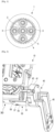
- FIG. 1 is a view illustrating a planetary gear device of the related art.
- a planetary gear device 1 may include a sun gear 2 disposed to rotate at the center of the planetary gear device 1, a plurality of planet gears 3 that revolve around the sun gear 2 like a planet, a ring gear 4 disposed on the outer periphery of the plurality of planet gears 3, and a carrier 5 in which the plurality of planet gears 3 are disposed.
- the sun gear 2 is coupled to a motor shaft (not illustrated) of the motor, when the motor shaft rotates, the sun gear 2 rotates integrally with the motor shaft.
- the plurality of planet gears 3 meshed with the sun gear 2, in the case of FIG. 1 , four planet gears 3 are rotated by the sun gear 2.
- the plurality of planet gears 3 are inscribed in the ring gear 4 having teeth formed on the inner circumferential surface. Accordingly, the plurality of planet gears 3 revolve around the sun gear 2 along the ring gear 4 while being rotated by the sun gear 2.
- the carrier 5 is rotated based on the sun gear 2 when the plurality of planet gears 3 revolve.
- the carrier 5 rotates by decelerating at a predetermined gear ratio compared to the rotation speed of the motor shaft.
- the gear ratio of the planetary gear device 1 is S/(S + R).
- S is the number of teeth of the sun gear 2
- R is the number of teeth of the ring gear 4.
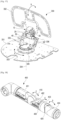
- FIG. 2 is a perspective view illustrating a planetary gear transmission device according to an embodiment
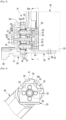
- FIG. 3 is a cross-sectional view illustrating a planetary gear transmission device according to an embodiment
- FIG. 4 is a cross-sectional view illustrating the planetary gear transmission device of FIG. 3 taken along line °-° according to an embodiment
- FIG. 5 is a perspective view illustrating a planetary gear device used in a planetary gear transmission device according to an embodiment according to an embodiment
- FIG. 6 is a perspective view illustrating a recursive rotation bracket of the planetary gear transmission device of FIG. 3 according to an embodiment.
- a planetary gear transmission device 10 includes a planetary gear device 20, a motor 30, a fixing bracket 40, and a recursive rotation bracket 50.
- the planetary gear device 20 includes a sun gear 22, a plurality of planet gears 23, a ring gear 24, and a carrier 25 supporting the plurality of planet gears 23.
- the planetary gear device 20 is the same as or similar to the planetary gear device 1 of the related art illustrated and described in FIG. 1 ; therefore, a detailed description thereof is omitted.
- the planetary gear device 20 is different from the planetary gear device 1 of the related art illustrated in FIG. 1 in that it includes a plurality of protrusions 26 provided on the outer circumferential surface of the ring gear 24 as illustrated in FIG. 5 .
- the motor 30 is formed to generate a rotational force that is input to the planetary gear device 20.
- the motor 30 includes a motor shaft 31 and a motor body 33.
- the motor body 33 may be formed to support the rotation of the motor shaft 31.
- a rotor (not illustrated) and a stator (not illustrated) may be provided inside the motor body 33 to rotate the motor shaft 31.
- a speed reducer (not illustrated) may be disposed inside the motor body 33.
- a reducer-integrated motor in which a reducer is built in the motor body 33 may be used.
- the reducer may reduce the rotation of the motor 30 by 1/350.
- a reducer integrated motor is used.
- a servo motor may be used as the motor 30.
- the fixing bracket 40 is formed to fix the planetary gear device 20.
- the fixing bracket 40 is formed to fix any one of the sun gear 22, the ring gear 24, and the carrier 25 of the planetary gear device 20 to prevent rotation. Accordingly, a part of the planetary gear device 20 fixed by the fixing bracket 40, that is, any one of the sun gear 22, the ring gear 24, and the carrier 25 of the planetary gear device 20, which is fixed by the fixing bracket 40, is not rotated when the motor shaft 31 rotates.
- the ring gear 24 of the planetary gear device 20 is fixed to the fixing bracket 40, when the motor shaft 31 of the motor 30 rotates, the ring gear 24 is not rotated and only the sun gear 22 and the plurality of planet gears 23 are rotated.
- the recursive rotation bracket 50 may be disposed on the motor 30.
- the recursive rotation bracket 50 is formed such that any one of the sun gear 22, the ring gear 24, and the carrier 25, which is not fixed by the fixing bracket 40, of the planetary gear device 20 is fixed to the recursive rotation bracket 50.
- the recursive rotation bracket 50 is formed such that the motor shaft 31 of the motor 30 transmits the rotational force to the other one among the sun gear 22, the ring gear 24, and the carrier 25 of the planetary gear device 20 that is not fixed to the fixing bracket 40 and the recursive rotation bracket 50.
- any one of the sun gear 22, the ring gear 24, and the carrier 25 of the planetary gear device 20 connected to the motor shaft 31 rotates, so that another one of the sun gear 22, the ring gear 24, and the carrier 25 of the planetary gear device 20 in which the recursive rotation bracket 50 is disposed is rotated.
- the motor body 33 that is, the motor 30 disposed in the recursive rotation bracket 50 is rotated.
- the recursive rotation bracket 50 is rotated by a certain angle by the rotation of the motor shaft 31, and thereby the motor 30 itself is rotated at the certain angle.
- the rotational force of the motor shaft 31 is output through the recursive rotation bracket 50.
- an output part may be disposed on the recursive rotation bracket 50.
- the output part may be disposed on the motor 30 fixed to the recursive rotation bracket 50.
- the motor 30 Because the motor 30 is fixed to the recursive rotation bracket 50, the motor 30 rotates in the same manner as the recursive rotation bracket 50.
- any one of the sun gear 22, the ring gear 24, and the carrier 25 of the planetary gear device 20 is used as any one of a fixing part to fix the planetary gear device 20, an input part to which the rotational force of the motor 30 is input, and an output part through which the rotational force passing through the planetary gear device 20 is output will be described in detail.
- the fixing bracket 40 may be formed to fix the ring gear 24 of the planetary gear device 20. Therefore, when the motor shaft 31 rotates, the ring gear 24 disposed on the fixing bracket 40 is not rotated.
- the fixing bracket 40 may include a receiving portion 41 and an extending portion 46.
- the receiving portion 41 may include a circular insertion groove 42 into which the ring gear 24 of the planetary gear device 20 is inserted.
- the diameter of the insertion groove 42 of the receiving portion 41 may be formed to correspond to the outer diameter of the planetary gear device 20, that is, the outer diameter of the ring gear 24.
- a plurality of grooves 43 corresponding to the plurality of protrusions 26 of the planetary gear device 20 may be provided around the insertion groove 42.
- a step portion 44 may be provided at the bottom of the insertion groove 42.
- the step portion 44 may be formed as a circular groove having a diameter less than the diameter of the insertion groove 42.
- the width of the step portion 44 may be determined to stably support the ring gear 24.
- the depth of the step portion 44 may be determined so that the tips of a plurality of shafts 29 protruding from the carrier 25 do not touch the bottom of the step portion 44.
- a bearing groove 45 may be provided in the center of the step portion 44.
- a bearing 67 for supporting one end of an adapter 60 in which the sun gear 22 is disposed may be disposed in the bearing groove 45.
- the extending portion 46 may extend from the outer circumferential surface of the receiving portion 41 and may be formed to be fixed to another part on which the fixing bracket 40 is disposed.
- the extending portion 46 of the fixing bracket 40 may be fixed to a main body of the robot.
- the recursive rotation bracket 50 may be disposed to rotate integrally with the carrier 25.
- the recursive rotation bracket 50 is not directly fixed to the carrier 25, but is fixed to the opposite side of the plurality of planet gears 23 disposed on the carrier 25.
- the carrier 25 and the recursive rotation bracket 50 may be disposed to support both ends of the plurality of planet gears 23.
- the carrier 25 may be formed in a disk shape and provided with a plurality of through holes 27 corresponding to the plurality of planet gears 23.
- the carrier 25 may be formed in a disk shape and provided with a plurality of through holes 27 corresponding to the plurality of planet gears 23.
- the carrier 25 may be formed in a disk shape and provided with a plurality of through holes 27 corresponding to the plurality of planet gears 23.
- the carrier 25 may be formed in a disk shape and provided with a plurality of through holes 27 corresponding to the plurality of planet gears 23.
- a center hole 28 through which the adapter 60 to be described later passes may be formed in the center of the carrier 25.
- the plurality of through holes 27 may be formed around the center hole 28 of the carrier 25 at predetermined intervals.
- a shaft hole 23a may be formed in the center of each of the plurality of planet gears 23.
- the motor 30 may be disposed on the recursive rotation bracket 50 to transmit power to the sun gear 22.
- the recursive rotation bracket 50 may include a planetary gear fixing portion 51 and a motor fixing portion 55.
- the planetary gear fixing portion 51 and the motor fixing portion 55 may be formed to form a substantially right angle. Therefore, the recursive rotation bracket 50 may be formed in an approximately L-shape.
- the planetary gear fixing portion 51 may be provided with a plurality of fixing holes 52 corresponding to the plurality of planet gears 23 and an adaptor hole 53 through which the adapter 60 connected to the motor shaft 31 passes.
- the plurality of fixing holes 52 may be formed around the adapter hole 53 at predetermined intervals.
- the adapter 60 may be formed to connect the sun gear 22 and the motor shaft 31 to transmit the power of the motor shaft 31 to the sun gear 22.
- a connecting plate 34 may be disposed at the front end of the motor shaft 31.
- the connecting plate 34 may be coupled to the front end of the motor shaft 31 so as to rotate integrally with the motor shaft 31.
- the connecting plate 34 may be formed in a substantially disk shape and have a plurality of fastening holes 35 provided around the motor shaft 31. Female threads may be formed in the plurality of fastening holes 35.
- the adapter 60 may be coupled to the sun gear 22, and may be fixed to the connecting plate 34 coupled to the motor shaft 31.
- the adapter 60 may include a base portion 61 and a shaft portion 65 protruding perpendicularly from the center of the base portion 61.
- the base portion 61 may be formed in a disk corresponding to the connecting plate 34 of the motor 30, and may have a plurality of fixing holes 62 formed around the shaft portion 65 at predetermined intervals. Accordingly, when a plurality of bolts 64 are fastened to the plurality of fastening holes 35 of the connecting plate 34 through the plurality of fixing holes 62, the adapter 60 is fixed to the connecting plate 34.
- the shaft portion 65 may extend vertically from the center of the base portion 61, and the sun gear 22 may be coupled to the shaft portion 65.
- a shaft hole 22a into which the shaft portion 65 is inserted may be provided in the center of the sun gear 22. Accordingly, the sun gear 22 may rotate integrally with the shaft portion 65.
- the front end of the shaft portion 65 may be supported by the bearing 67 disposed at the bottom of the receiving portion 41 of the fixing bracket 40.
- the connecting plate 34 is rotated, and when the connecting plate 34 rotates, the adapter 60 rotates integrally with the connecting plate 34.
- the sun gear 22 fixed to the shaft portion 65 of the adapter 60 rotates integrally with the adapter 60.
- each of the plurality of shafts 29 may include a head portion 29a formed at one end of the shaft 29 and a ring groove 29b formed at the other end thereof.
- the head portion 29a may be formed to have a diameter larger than the diameter of the shafts 29.
- the ring groove 29b may be formed as a groove having a predetermined depth along the outer circumferential surface of the shafts 29 so that a snap ring 29c is inserted into the ring groove 29b.
- the shaft holes 23a of the plurality of planet gears 23, and the plurality of through holes 27 of the carrier 25 and the plurality of snap rings 29c are disposed in the ring grooves 29b of the tips of the plurality of shafts 29 protruding outward of the carrier 25, the recursive rotation bracket 50, the plurality of planet gears 23, and the carrier 25 are integrally fixed.
- the carrier 25 and the recursive rotation bracket 50 are rotated integrally.
- the plurality of planet gears 23 may rotate with respect to the plurality of shafts 29, respectively.
- the motor fixing portion 55 may be provided with a plurality of motor fixing holes 56 for fixing the motor 30.
- One side surface of the motor 30 may be provided with a plurality of female screws corresponding to the plurality of motor fixing holes 56.
- a plurality of sub-motor fixing portions 58 may be provided in the planetary gear fixing portion 51.
- the plurality of sub-motor fixing portions 58 may be provided with sub fixing holes 58a.
- a plurality of front female screws corresponding to the plurality of sub fixing holes 58a may be provided on the front surface of the motor 30.
- the recursive rotation bracket 50 when the recursive rotation bracket 50 is disposed on the motor 30 with the motor fixing portion 55 and the plurality of sub-motor fixing portions 58, the recursive rotation bracket 50 and the motor 30 may be firmly coupled to each other.
- the motor 30 and the recursive rotation bracket 50 are coupled to each other using the plurality of bolts, but the method of coupling the motor 30 and the recursive rotation bracket 50 is not limited thereto. Although not illustrated, various coupling methods may be used as long as the motor 30 and the recursive rotation bracket 50 can be coupled to each other.
- the adapter 60 disposed at the front end of the motor shaft 31 may protrude through the adapter hole 53 of the recursive rotation bracket 50.
- the shaft portion 65 of the adapter 60 may be coupled to the sun gear 22 disposed at the center of the plurality of planet gears 23. Accordingly, when the motor shaft 31 rotates, the sun gear 22 is rotated integrally with the motor shaft 31 by the connecting plate 34 and the adapter 60.
- the sun gear 22 rotates
- the plurality of planet gears 23 meshed with the sun gear 22 are rotated.
- the carrier 25 and the recursive rotation bracket 50 are rotated based on the rotation axis of the sun gear 22, that is, the central axis of the motor shaft 31.
- the sun gear 22 rotates
- the plurality of planet gears 23 meshed with the sun gear 22 are rotated based on the shafts 29, respectively, and are revolved along the ring gear 24.
- the revolving rotation of the plurality of planet gears 23 causes the carrier 25 and the recursive rotation bracket 50 to rotate based on the central axis of the sun gear 22.
- An output member may be fixed to the recursive rotation bracket 50.
- the recursive rotation bracket 50 may be fixed to the head of the robot. In this case, when the recursive rotation bracket 50 rotates, the head of the robot may be rotated at a predetermined angle with respect to the main body.
- the gear ratio of the planetary gear transmission device 10 may be different from that of the planetary gear device of the related art.
- the gear ratio of the planetary gear device 1 of the related art is S/(S + R).
- S is the number of teeth of the sun gear
- R is the number of teeth of the ring gear.
- the carrier 25 when the sun gear 22 is rotated N by the motor 30, the carrier 25 is rotated bN. Because the carrier 25 is provided with the recursive rotation bracket 50, when the carrier 25 rotates, the recursive rotation bracket 50 integrally rotates. Accordingly, the output member fixed to the recursive rotation bracket 50 is rotated bN. As a result, the torque by the planetary gear transmission device 10 according to an embodiment may be increased by 1/b times by the gear ratio.
- the gear ratio is different from that of the planetary gear device 1 of the related art.
- the recursive rotation bracket 50 is disposed on the opposite side of the carrier 25 based on the plurality of planet gears 23.
- the installation of the recursive rotation bracket 50 is not limited thereto.
- the recursive rotation bracket 50 may be directly fixed to the carrier 25.
- the motor shaft 31 and the sun gear 22 are connected to each other using the adapter 60 and the connecting plate 34, but the connection of the motor shaft 31 and the sun gear 22 is not limited thereto.
- the sun gear 22 may be directly disposed at the front end of the motor shaft 31'.
- FIG. 7 is a cross-sectional view illustrating a planetary gear transmission device according to an embodiment.
- the motor shaft 31' protrudes through the adaptor hole 53 of the recursive rotation bracket 50.
- the motor shaft 3 1' is coupled to the sun gear 22 disposed at the center of the plurality of planet gears 23. Accordingly, when the motor shaft 31' rotates, the sun gear 22 rotates integrally with the motor shaft 31'.
- the planetary gear transmission device 10' shown in FIG. 7 is different from the planetary gear transmission device 10 according to the above-described embodiment only in the connection structure between the motor shaft 31' and the sun gear 22, so a detailed description thereof is omitted.
- the planetary gear transmission device 10 uses the planetary gear device 20 including the plurality of protrusions 26 provided on the outer circumferential surface of the ring gear 24 as illustrated in FIG. 5 .
- the planetary gear transmission device 10 according to an embodiment may be implemented using the planetary gear device 1 without the protrusions on the outer circumferential surface of the ring gear as illustrated in FIG. 1 .
- a planetary gear transmission device 110 in which a carrier 25 of a planetary gear device 20 is fixed, a sun gear 22 is used as an input part, and a ring gear 24 is uses as an output part will be described in detail with reference to FIGS. 8 , 9 , 10 , and 11 .
- FIG. 8 is a perspective view illustrating a planetary gear transmission device according to an embodiment.
- FIG. 9 is a cross-sectional view illustrating a planetary gear transmission device according to an embodiment.
- FIG. 10 is a cross-sectional view illustrating the planetary gear transmission device of FIG. 9 taken along line ⁇ - ⁇ according to an embodiment.
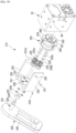
- FIG. 11 is an exploded perspective view illustrating the planetary gear transmission device of FIG. 9 according to an embodiment.
- a fixing bracket 140 may be formed to fix a carrier 125 of a planetary gear device 120. Therefore, when the motor shaft 31 rotates, the carrier 125 disposed on the fixing bracket 140 is not rotated.
- the fixing bracket 140 may include a fixing portion 141 and an extension portion 146.
- the fixing portion 141 may be formed in a cylindrical shape to fix the carrier 125 of the planetary gear device 120. Therefore, the carrier 125 may be fixed to one end of the fixing portion 141. In the case of the embodiment shown in FIGS. 9, 10 , and 11 , the carrier 125 may be formed integrally with the top surface of the fixing portion 141. In other words, the top surface of the fixing portion 141 may be formed to serve as the carrier 125.
- a plurality of holes 142 corresponding to a plurality of through holes 127 and a center hole 128 of the carrier 125 may be formed inside the fixing portion 141 having the cylindrical shape.
- the carrier 125 may be formed in a disk shape and provided with the plurality of through holes 127 corresponding to a plurality of planet gears 123. For example, when the planetary gear device 120 includes four planet gears 123, four through holes 127 are formed in the carrier 125.
- the center hole 128 through which an adapter 60 disposed on the motor shaft 31 passes may be formed in the center of the carrier 125.
- the plurality of through holes 127 may be formed around the center hole 128 of the carrier 125 at predetermined intervals.
- a shaft hole 123a may be formed in the center of each of the plurality of planet gears 123.
- each of the plurality of shafts 129 may include a head portion 129a formed at one end of the shaft 129 and a ring groove 129b formed at the other end thereof.
- the head portion 129a may be formed to have a diameter larger than the diameter of the shaft 129.
- the ring groove 129b may be formed as a groove having a predetermined depth along the outer circumferential surface of the shaft 29 so that a snap ring 129c is inserted into the ring groove 129b.
- the plurality of shafts 129 are inserted into the plurality of shaft holes 123a of the plurality of planet gears 123 and the plurality of through holes 127 of the carrier 125, and the plurality of snap rings 129c are disposed in the ring grooves 129b of the tips of the plurality of shafts 129 protruding downward of the carrier 125, the plurality of planet gears 123 are fixed to the carrier 125.
- each of the plurality of planet gears 123 may rotate with respect to each of the plurality of shafts 129 while being disposed on the carrier 125.
- the extension portion 146 may extend from the other end of the fixing portion 141 and may be formed to be fixed to another component on which the fixing bracket 140 is disposed.
- the extension portion 146 of the fixing bracket 140 may be fixed to the main body of the robot.
- a recursive rotation bracket 150 may be disposed to rotate integrally with the ring gear 124.
- the ring gear 124 is fixed to the recursive rotation bracket 150, so that when the ring gear 124 rotates, the recursive rotation bracket 150 is rotated integrally with the ring gear 124.
- the motor 30 may be disposed on the recursive rotation bracket 150 to transmit power to the sun gear 122.
- the recursive rotation bracket 150 may include a ring gear fixing portion 151 and a motor fixing portion 155.
- the ring gear fixing portion 151 and the motor fixing portion 155 may be formed to form a substantially right angle. Accordingly, the recursive rotation bracket 150 may be formed in an approximately L-shape.
- the ring gear fixing portion 151 may be formed integrally with the ring gear 124.
- the ring gear 124 may be formed in the ring gear fixing portion 151. Then, when the ring gear 124 rotates, the recursive rotation bracket 150 rotates integrally with the ring gear 124.
- the ring gear fixing portion 151 and the ring gear 124 may be separately formed.
- a ring gear hole into which the ring gear 24 of the planetary gear device 20 as illustrated in FIG. 5 is inserted may be formed in the ring gear fixing portion 151, and the ring gear 24 may be connected to the ring gear hole.
- a plurality of grooves corresponding to the plurality of protrusions 26 of the planetary gear device 20 may be provided around the ring gear hole.
- the motor fixing portion 155 may be provided with a plurality of motor fixing holes 156 for fixing the motor 30.
- a plurality of female screws corresponding to the plurality of motor fixing holes 156 may be provided on one side surface of the motor 30.
- the recursive rotation bracket 150 may include a sub-motor fixing portion 158.
- the sub-motor fixing portion 158 may be provided on the ring gear fixing portion 151 and may be formed to be fixed to the front surface of the motor 30.
- the recursive rotation bracket 150 includes two sub-motor fixing portions 158.
- a sub fixing hole 158a may be provided at the front end of the sub-motor fixing portion 158.
- a front female screw corresponding to the sub fixing hole 158a of the sub-motor fixing portion 158 may be provided on the front surface of the motor 30. Therefore, when a bolt 159 is fastened to the front female screw of the motor 30 through the sub fixing hole 158a of the sub-motor fixing portion 158, the recursive rotation bracket 150 may be fixed to the front surface of the motor 30.
- the recursive rotation bracket 150 when the recursive rotation bracket 150 is disposed on the motor 30 with the motor fixing portion 155 and the plurality of sub-motor fixing portions 158, the recursive rotation bracket 150 and the motor 30 may be firmly coupled to each other.
- the motor shaft 31 of the motor 30 and the sun gear 122 of the planetary gear device 120 may be connected by an adapter 60 and a connecting plate 34. Accordingly, when the motor shaft 31 rotates, the sun gear 122 is rotated integrally with the motor shaft 31.
- each of the plurality of planet gears 123 meshed with the sun gear 122 rotates about the shaft 129.
- the carrier 125 is integrally formed with the fixing bracket 140, when the sun gear 122 rotates, the carrier 125 is not rotated and the plurality of planet gears 123 meshed with the sun gear 122 are rotated based on the plurality of shafts 129, respectively. Then, the ring gear 124 is rotated based on the central axis of the sun gear 122 by the rotation of the plurality of planet gears 123.
- An output member may be fixed to the recursive rotation bracket 150.
- the recursive rotation bracket 150 may be fixed to the head of the robot. In this case, when the recursive rotation bracket 150 rotates, the head of the robot may be rotated at a predetermined angle with respect to the main body.
- the motor 30 fixed to the recursive rotation bracket 150 when the recursive rotation bracket 150 rotates, the motor 30 fixed to the recursive rotation bracket 150 also rotates integrally with the recursive rotation bracket 150.
- the rotation of the recursive rotation bracket 150 further rotates the motor shaft 31 by a predetermined angle.
- the gear ratio of the planetary gear transmission device 110 may be different from that of the planetary gear device 1 of the related art.
- the gear ratio of the planetary gear device 1 of the related art is -S/R.
- S is the number of teeth of the sun gear
- R is the number of teeth of the ring gear.
- the rotation of the ring gear 124 causes the motor 30 to rotate by a predetermined angle. Accordingly, the sun gear 22 is also rotated at the same angle as the motor 30.
- the ring gear 124 when the sun gear 122 is rotated N by the motor 30, the ring gear 124 is rotated -aN. Because the ring gear 124 is disposed in the recursive rotation bracket 150, when the ring gear 124 rotates, the recursive rotation bracket 150 integrally rotates. Accordingly, the output member fixed to the recursive rotation bracket 150 rotates -aN. As a result, the torque by the planetary gear transmission device 110 according to an embodiment may be increased by 1/a times due to the gear ratio.
- the gear ratio is different from that of the planetary gear device 1 of the related art.
- a planetary gear transmission device 210 in which a sun gear 222 of a planetary gear device 220 is fixed, a ring gear 224 is used as an input part, and a carrier 225 is used as an output part will be described in detail with reference to FIGS. 12 , 13 , 14 , and 15 .
- FIG. 12 is a perspective view illustrating a planetary gear transmission device according to an embodiment.
- FIG. 13 is a cross-sectional view illustrating a planetary gear transmission device according to an embodiment.
- FIG. 14 is a cross-sectional view illustrating the planetary gear transmission device of FIG. 13 taken along line 2_2 according to an embodiment of the disclosure.
- FIG. 15 is an exploded perspective view illustrating the planetary gear transmission device of FIG. 13 according to an embodiment.
- a fixing bracket 240 may be formed to fix a sun gear 222 of a planetary gear device 220. Therefore, when the motor shaft 31 rotates, the sun gear 222 disposed on the fixing bracket 240 is not rotated.
- the fixing bracket 240 may include a fixing portion 241 and an extension portion 246.
- the fixing portion 241 may be formed in a cylindrical shape to fix the sun gear 222 of the planetary gear device 220.
- a bearing support portion 243 may be formed at the front end of the fixing portion 241, and a sun gear fixing portion 244 may be formed at the leading end of the bearing support portion 243.
- the diameter of the bearing support portion 243 may be formed smaller than the diameter of the fixing portion 241. Accordingly, a step capable of supporting a bearing 267 may be formed between the fixing portion 241 and the bearing support portion 243.
- the diameter of the sun gear fixing portion 244 may be formed smaller than the diameter of the bearing support portion 243. Accordingly, a step capable of supporting the sun gear 222 may be formed between the bearing support portion 243 and the sun gear fixing portion 244.
- a sun gear hole 222a into which the sun gear fixing portion 244 is inserted may be formed in the center of the sun gear 222.
- the sun gear fixing portion 244 is inserted into the sun gear hole 222a, and the sun gear 222 is fixed so as not to rotate with respect to the sun gear fixing portion 244.
- the extension portion 246 may extend from the other end of the fixing portion 241 and may be formed to be fixed to another component on which the fixing bracket 240 is disposed.
- the extension portion 246 of the fixing bracket 240 may be fixed to the main body of the robot.
- a recursive rotation bracket 250 may be disposed to rotate integrally with the carrier 225.
- the recursive rotation bracket 250 may be formed to be fixed to the carrier 225. Accordingly, when the carrier 225 rotates, the recursive rotation bracket 250 may be rotated integrally with the carrier 225.
- the motor 30 may be disposed on the recursive rotation bracket 250 to transmit power to the ring gear 224.
- the recursive rotation bracket 250 may include a carrier fixing portion 251 and a motor fixing portion 255.
- the carrier fixing portion 251 and the motor fixing portion 255 may be formed to form a substantially right angle.
- the recursive rotation bracket 250 may be formed in an approximately U-shape with a flat bottom.
- the carrier 225 may be disposed on one surface of the carrier fixing portion 251.
- the carrier 225 may be formed integrally with the carrier fixing portion 251 or may be formed separately from the carrier fixing portion 251.
- the carrier 225 may be fixed to the carrier fixing portion 251 with fastening elements such as bolts.
- the carrier 225 is integrally formed on the upper surface of the carrier fixing portion 251.
- the carrier 225 may be formed in a disk shape, and may be provided with a plurality of through holes 227 corresponding to a plurality of planet gears 223. For example, when the planetary gear device 220 includes four planet gears 223, four through holes 227 are formed in the carrier 225.
- the carrier fixing portion 251 may be provided with four fixing holes 252 corresponding to the four through holes 227 of the carrier 225.
- the carrier 225 and the carrier fixing portion 251 are integrally formed, the four through holes 227 of the carrier 225 and the four fixing holes 252 of the carrier fixing portion 251 may be formed integrally, respectively.
- a center hole 228 through which the sun gear fixing portion 244 of the fixing portion 241 passes may be formed in the center of the carrier 225.
- the plurality of through holes 227 may be formed around the center hole 228 of the carrier 225 at predetermined intervals.
- a bearing hole 253 that corresponds to the center hole 228 of the carrier 225 and through which the fixing portion 241 of the fixing bracket 240 passes may be formed in the center of the carrier fixing portion 251.
- the plurality of fixing holes 252 may be formed at predetermined intervals around the bearing hole 253 of the carrier fixing portion 251.
- the center hole 228 of the carrier 225 and the bearing hole 253 of the carrier fixing portion 251 may be formed integrally.
- a bearing 267 may be disposed in the bearing hole 253 of the carrier fixing portion 251 and may support the carrier fixing portion 251 to rotate smoothly with respect to the fixing portion 241. Accordingly, the recursive rotation bracket 250 may rotate based on the fixing portion 241 of the fixing bracket 240.
- a shaft hole 223a may be formed in the center of each of the plurality of planet gears 223.
- each of the plurality of shafts 229 may include a head portion 229a formed at one end of the shaft 229 and a ring groove 229b formed at the other end thereof.
- the head portion 229a may be formed to have a diameter larger than the diameter of the shaft 229.
- the ring groove 229b may be formed as a groove having a predetermined depth along the outer circumferential surface of the shaft 229 so that a snap ring 229c is inserted into the ring groove 229b.
- the plurality of shafts 229 are inserted into the plurality of shaft holes 223a of the plurality of planet gears 223 and the plurality of through holes 227 of the carrier 225, and the plurality of snap rings 229c are disposed in the ring grooves 229b of the tips of the plurality of shafts 229 protruding outward of the carrier 225, the plurality of planet gears 223, the carrier 225, and the carrier fixing portion 251 of the recursive rotation bracket 250 are integrally fixed.
- each of the plurality of planet gears 223 may rotate with respect to each of the plurality of shafts 229.
- the motor fixing portion 255 may be provided with a plurality of motor fixing holes 256 for fixing the motor 30.
- the motor fixing portion 255 may be formed in two flat plates extending vertically from both ends of the carrier fixing portion 251.
- Both side surfaces of the motor 30 may be provided with a plurality of female screws 39 corresponding to the plurality of motor fixing holes 256 formed in the motor fixing portion 255.
- An adapter 260 may be formed to connect the ring gear 224 and the motor shaft 31 so that the power of the motor shaft 31 is transmitted to the ring gear 224.
- a connecting plate 34 may be disposed at the front end of the motor shaft 31.
- the connecting plate 34 may be formed to rotate integrally with the motor shaft 31 at the front end of the motor shaft 31.
- the connecting plate 34 may be formed in a substantially disk shape, and may be provided with a plurality of fastening holes 35 formed around the motor shaft 31.
- a female screw may be formed in each of the plurality of fastening holes 35.
- the adapter 260 may be coupled to the ring gear 224, and may be fixed to the connecting plate 34 connected to the motor shaft 31.
- the adapter 260 may be formed integrally with the ring gear 224.
- the adapter 260 may include a base portion 261, a connecting portion 263, and a ring gear plate 265.
- the base portion 261 may be formed in a disk corresponding to the connecting plate 34 of the motor 30, and may be provided with a plurality of fixing holes 262 that are formed around the connecting portion 263 at predetermined intervals. Accordingly, when the plurality of bolts 264 are fastened to the plurality of fastening holes 35 of the connecting plate 34 through the plurality of fixing holes 262, the adapter 260 is fixed to the connecting plate 34.
- the connecting portion 263 may be extend vertically from the center of the base portion 261, and may be connected to the ring gear plate 265.
- the connecting portion 263 may be integrally formed with the base portion 261 and the ring gear plate 265.
- the ring gear plate 265 may be formed integrally with the ring gear 224.
- the ring gear plate 265 may be formed separately from the ring gear 224, and may be coupled to the ring gear 224 by fastening elements such as bolts.
- the connecting plate 34 disposed at the front end of the motor shaft 31 is connected to the adapter 260 coupled to the ring gear 224. Accordingly, when the motor shaft 31 rotates, the connecting plate 34 is rotated. When the connecting plate 34 rotates, the adapter 260 is rotated integrally with the connecting plate 34.
- the ring gear 224 fixed to the ring gear plate 265 of the adapter 260 may rotate integrally with the motor shaft 31.
- An output member may be fixed to the recursive rotation bracket 250.
- the recursive rotation bracket 250 may be fixed to the head of the robot. In this case, when the recursive rotation bracket 250 rotates, the head of the robot may be rotated at a predetermined angle with respect to the main body.
- the motor 30 fixed to the recursive rotation bracket 250 when the recursive rotation bracket 250 rotates, the motor 30 fixed to the recursive rotation bracket 250 also rotates integrally with the recursive rotation bracket 250.
- the rotation of the recursive rotation bracket 250 further rotates the motor shaft 31 by a predetermined angle.
- the gear ratio of the planetary gear transmission device 210 according to an embodiment may be different from that of the planetary gear device of the related art.
- the gear ratio of the planetary gear device 1 of the related art is R/(S+R).
- S is the number of teeth of the sun gear
- R is the number of teeth of the ring gear.
- the rotation of the carrier 225 causes the motor 30 to rotate by a predetermined angle. Accordingly, the ring gear 224 is also rotated at the same angle as the motor 30.
- the carrier 225 when the ring gear 224 is rotated N by the motor 30, the carrier 225 is rotated (1/b)N. Because the carrier 225 is disposed in the recursive rotation bracket 250, when the carrier 225 rotates, the recursive rotation bracket 250 integrally rotates. Accordingly, the output member fixed to the recursive rotation bracket 250 rotates (1/b)N. As a result, the torque by the planetary gear transmission device 210 according to an embodiment may be increased by b times due to the gear ratio.
- the gear ratio is different from that of the planetary gear device 1 of the related art.
- the size of the planetary gear transmission device may be reduced compared to the planetary gear transmission device of the related art in which the input part and the output part are disposed on opposite sides of the planetary gear device interposed therebetween.
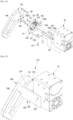
- FIG. 16 is a perspective view illustrating a robot using a planetary gear transmission device according to an embodiment.
- a robot 300 shown in FIG. 16 represents a robot that is capable of autonomous movement to transport items that may be used in stores, etc. and has a head 320 to be rotated at a predetermined angle.
- a robot 300 may include a main body 310 and a head 320.
- the main body 310 is provided with a plurality of wheels (not illustrated) at the lower part of the main body 310, so that the main body 310 may be driven autonomously.
- Shelves 312 capable of receiving items may be provided at the rear of the main body 310.
- the shelves 312 may be formed in an appropriate shape according to the type of the item carried by the robot 300.
- the head 320 is disposed on the upper end of the main body 310 and may be formed to rotate at a predetermined angle in a vertical direction and a horizontal direction with the main body 310.
- the planetary gear transmission device 10, 110, and 210 according to an embodiment may be used as a joint 330 connecting the head 320 and the main body 310.
- FIG. 17 is a perspective view illustrating a structure of a joint connecting a main body and a head of the robot of FIG. 16 according to an embodiment.
- FIG. 17 shows a state in which covers covering the main body 310 and the head 320 are removed from the robot 300 of FIG. 16 .
- the joint 330 connecting the main body 310 and the head 320 of the robot 300 may include a main body frame 331, a head frame 332, and a planetary gear transmission device 10.
- the main body frame 331 may be disposed on the upper end of the main body 310, and the planetary gear transmission device 10 may be disposed in the main body frame 331.
- a horizontal rotation part 333 that allows the head frame 332 to rotate in the left-and-right direction (arrow A) with respect to the main body frame 331 around a vertical axis 334 perpendicular to the main body frame 331 may be disposed on the upper surface of the main body frame 331.
- a pair of fixing parts 335 for supporting the head frame 332 may be provided on the upper surface of the horizontal rotation part 333.
- the pair of fixing parts 335 may be disposed at a predetermined distance apart from each other on the upper surface of the horizontal rotation part 333.
- the fixing bracket 40 and a support bracket 90 connected to the planetary gear transmission device 10 may be disposed at the pair of fixing parts 335, respectively.
- the head frame 332 may be disposed to rotate at a predetermined angle with respect to the main body 310, that is, the main body frame 331.
- the head frame 332 may be disposed to rotate at a predetermined angle in the vertical direction (arrow B) around a horizontal axis 336 parallel to the upper surface of the main body frame 331.
- the head frame 332 may be referred to as a moving member capable of rotating at a predetermined angle with respect to the main body 310.
- the planetary gear transmission device 10 may be disposed between the main body 310 and the head 320, and may allow the head 320 to rotate at a predetermined angle in the vertical direction with respect to the main body 310.
- the planetary gear transmission device 10 is disposed between the main body frame 331 and the head frame 332, and allows the head frame 332 to rotate at a predetermined angle in the vertical direction with respect to the main body frame 331.
- the head frame 332 is fixed to the output part of the planetary gear transmission device 10, so that the head frame 332 may be rotated at a predetermined angle by the output of the planetary gear device 20.
- the motor 30 for inputting power to the planetary gear device 20 is disposed at the output part of the planetary gear device 20.
- the planetary gear transmission device 10 may be formed to output power of the motor 30 through any one of the carrier 25, the ring gear 24, and the sun gear 22 of the planetary gear device 20.
- any one of the above-described various planetary gear transmission devices 10, 110, 210 may be disposed.
- FIG. 17 illustrates the structure of the joint 330 connecting the main body 310 and the head 320 of the robot 300, and the planetary gear transmission device 10, in which the rotational force of the motor 30 is input to the sun gear 22, and then is output through the carrier 25 as illustrated in FIGS. 2 , 3 , 4 , and 5 , is applied to the joint 330.
- the planetary gear transmission device 10 may include the planetary gear device 20, the fixing bracket 40, the recursive rotation bracket 50, and the motor 30.
- the planetary gear device 20 may include a sun gear 22, a ring gear 24, a plurality of planet gears 23, and a carrier 25 supporting the plurality of planet gears 23, and the ring gear 24 may be fixed to the main body 310.
- the ring gear 24 is fixed to the fixing bracket 40, and the fixing bracket 40 is disposed on the main body frame 331.
- the fixing bracket 40 is disposed on one of the pair of fixing parts 335 disposed on the horizontal rotation part 333 of the main body frame 331.
- the support bracket 90 is disposed on the other one of the pair of fixing parts 335 of the horizontal rotation part 333 to face the fixing bracket 40.
- the support bracket 90 may be disposed to rotatably support the other end of the motor 30.
- the motor 30 may rotate with respect to the fixing bracket 40 and the support bracket 90 based on a straight line passing through the motor shaft 31 (see FIG. 3 ), that is, the horizontal axis 336.
- the head frame 332 also rotates.
- the motor 30 is disposed in the recursive rotation bracket 50, and the motor shaft 31 of the motor 30 is connected to the sun gear 22 of the planetary gear device 20. Further, the recursive rotation bracket 50 is fixed to the carrier 25 of the planetary gear device 20.
- the motor 30 is rotated by the recursive rotation bracket 50, and the head frame 332 is also rotated. In other words, the motor 30 and the head frame 332 are rotated at the same time by the recursive rotation bracket 50.
- the sun gear 22 of the planetary gear device 20 is rotated. Because the ring gear 24 is fixed by the fixing bracket 40 disposed on the main body frame 331, when the sun gear 22 of the planetary gear device 20 rotates, the carrier 25 is rotated. In other words, the rotation of the motor 30 input to the sun gear 22 is output as the rotation of the carrier 25.
- the recursive rotation bracket 50 is fixed to the carrier 25, when the carrier 25 rotates, the recursive rotation bracket 50 rotates integrally. Because the motor 30 is fixed to the recursive rotation bracket 50, when the recursive rotation bracket 50 rotates, the motor 30 rotates integrally with the recursive rotation bracket 50.
- the motor 30 is fixed to the head frame 332, when the motor 30 rotates, the head frame 332 is rotated integrally with the motor 30.
- the recursive rotation bracket 50 is rotated through the sun gear 22 and the carrier 25 of the planetary gear device 20 so that the head frame 332 is rotated.
- FIG. 18 is a perspective view illustrating a robot arm manipulator using a planetary gear transmission device according to an embodiment.
- FIG. 19 is an exploded perspective view illustrating a pitch rotation axis of the robot arm manipulator of FIG. 18 according to an embodiment.
- the robot arm manipulator 400 may include a plurality of arm parts 401, 402, 403, and 404, two pitch rotation axes 410 and 420, and one roll rotation axis 430.
- a first pitch rotation axis 410 may be disposed between a first arm part 401 and a second arm part 402, and may be formed to allow the second arm part 402 to rotate at a predetermined angle in a direction perpendicular to the first arm part 401 (arrow C).
- the first arm part 401 may be disposed on a main body.
- the first arm part 401 may be disposed to rotate with respect to the main body.
- a second pitch rotation axis 420 may be disposed between a third arm part 403 and a fourth arm part 404, and may be formed to allow the fourth arm part 404 to rotate at a predetermined angle in a direction perpendicular to the third arm part 403 (arrow D).
- a hand capable of holding an object may be disposed at the tip of the fourth arm part 404.
- the roll rotation axis 430 may be disposed between the second arm part 402 and the third arm part 403, and may be formed to allow the third arm part 403 to rotate in both directions (arrow E) around the central axis of the second arm part 402.
- the first pitch rotation axis 410, the second pitch rotation axis 420, and the roll rotation axis 430 may use the planetary gear transmission device 10 according to an embodiment as described above.
- FIG. 19 illustrates the first pitch rotation axis 410 of the robot arm manipulator 400 to which the planetary gear transmission device 10, in which the power of the motor 30 is input to the sun gear 22, and then is output through the carrier 25 as illustrated in FIGS. 2 , 3 , 4 , and 5 , is applied.
- One end of the second arm part 402 may be coupled to one end of the first arm part 401 to rotate at a predetermined angle in the vertical direction with respect to the first arm part 401.
- the planetary gear transmission device 10 may be disposed between one end of the first arm part 401 and one end of the second arm part 402, and may allow the second arm part 402 to rotate at a predetermined angle with respect to one end of the first arm part 401.
- the planetary gear transmission device 10 may include the planetary gear device 20, the recursive rotation bracket 50, and the motor 30.
- the planetary gear device 20 may include a sun gear 22, a ring gear 24, a plurality of planet gears 23, and a carrier 25 supporting the plurality of planet gears 23, and the ring gear 24 may be fixed to one end of the first arm part 401.
- the ring gear 24 is fixed to the fixing bracket 40, and the fixing bracket 40 is disposed at one end of the first arm part 401. Because the other end of the first arm part 401 is disposed in the main body (not illustrated), the fixing bracket 40 is disposed in the main body.
- the motor 30 is disposed at one end of the second arm part 402.
- a motor bracket 411 is disposed at one end of the second arm part 402, and the motor 30 is fixed to the motor bracket 411. Accordingly, when the motor 30 rotates, the second arm part 402 rotates integrally with the motor 30.
- the motor 30 is disposed in the recursive rotation bracket 50, and the motor shaft 31 of the motor 30 is connected to the sun gear 22 of the planetary gear device 20 through an adapter 60. Further, the recursive rotation bracket 50 is fixed to the carrier 25 of the planetary gear device 20.
- the motor 30 is rotated by the recursive rotation bracket 50, and the second arm part 402 is also rotated.
- the motor 30 and the second arm part 402 are rotated at the same time by the recursive rotation bracket 50.
- the recursive rotation bracket 50 is fixed to the carrier 25, when the carrier 25 rotates, the recursive rotation bracket 50 rotates integrally. Because the motor 30 is fixed to the recursive rotation bracket 50, when the recursive rotation bracket 50 rotates, the motor 30 rotates integrally with the recursive rotation bracket 50.
- the motor 30 is fixed to the motor bracket 411 of the second arm part 402, when the motor 30 rotates, the second arm part 402 rotates integrally with the motor 30.
- the recursive rotation bracket 50 is rotated through the sun gear 22 and the carrier 25 of the planetary gear device 20 so that the second arm part 402 is rotated.
- the first arm part 401 functions as a main body fixing the planetary gear transmission device 10
- the second arm part 402 functions as a moving member that is rotated by the planetary gear transmission device 10.
- the second arm part 402 is fixed to the motor 30.
- the second arm part 402 may be directly fixed to the recursive rotation bracket 50, not the motor 30. Even in this case, when the recursive rotation bracket 50 rotates, the second arm part 402 is rotated.
- the planetary gear transmission device 10 in which the power of the motor 30 is input to the sun gear 22, and then is output through the carrier 25, is applied to the robot arm manipulator 400.
- the planetary gear transmission device applied to the robot arm manipulator 400 is not limited thereto.
- the planetary gear transmission devices 110 and 210 according to the other embodiments described above may be applied to the robot arm manipulator 400.
- FIG. 20 is a perspective view illustrating a robot waist joint using a planetary gear transmission device according to an embodiment.
- a robot waist joint 500 may be disposed between a lower body 501 and an upper body 502.
- the robot waist joint 500 may be provided so that the upper body 502 rotates at a predetermined angle in the front and rear direction (arrow F) with respect to the lower body 501.
- the robot waist joint 500 may include a fixed plate 510, a moving plate 520, and a planetary gear transmission device 10 disposed between the fixed plate 510 and the moving plate 520.
- the fixed plate 510 is fixed to the upper end of the lower body 501, and the moving plate 520 that is fixed to the lower end of the upper body 502 and provided to rotate at a predetermined angle with respect to the fixed plate 510.
- the planetary gear transmission device 10 allows the moving plate 520 to rotate with respect to the fixed plate 510 at a predetermined angle.
- the planetary gear device 20 may include a sun gear 22, a ring gear 24, a plurality of planet gears 23, and a carrier 25 supporting the plurality of planet gears 23, and the ring gear 24 may be fixed to the fixed plate 510.
- the ring gear 24 is fixed to the fixing bracket 40, and the fixing bracket 40 is disposed on the upper surface of the fixed plate 510. Because the fixed plate 510 is disposed on the upper end of the lower body 501, the fixing bracket 40 is disposed on the lower body 501.
- the motor 30 is disposed in the lower surface of the moving plate 520. Accordingly, when the motor 30 rotates, the moving plate 520 rotates integrally with the motor 30.
- the other end of the motor 30 may be supported by a support bracket 90 so that the moving plate 520 may stably rotate.
- the support bracket 90 may be disposed to rotatably support the motor 30 on the opposite side of the fixing bracket 40.
- the motor 30 is disposed in the recursive rotation bracket 50, and the motor shaft 31 of the motor 30 is connected to the sun gear 22 of the planetary gear device 20. Further, the recursive rotation bracket 50 is fixed to the carrier 25 of the planetary gear device 20.
- the recursive rotation bracket 50 is fixed to the carrier 25, when the carrier 25 rotates, the recursive rotation bracket 50 rotates integrally. Because the motor 30 is fixed to the recursive rotation bracket 50, when the recursive rotation bracket 50 rotates, the motor 30 rotates integrally with the recursive rotation bracket 50.
- the moving plate 520 rotates integrally with the motor 30.
- the recursive rotation bracket 50 is rotated through the sun gear 22 and the carrier 25 of the planetary gear device 20 so that the moving plate 520 is rotated.
- the fixed plate 510 is disposed on the upper end of the lower body 501 and the moving plate 520 is disposed on the lower end of the upper body 502, when the moving plate 520 is rotated with respect to the fixed plate 510, the upper body 502 is rotated at a predetermined angle with respect to the lower body 501.
- the lower body 501 functions as a main body fixing the planetary gear transmission device 10
- the upper body 502 functions as a moving member that is rotated by the planetary gear transmission device 10.
- the moving plate 520 is fixed to the motor 30.
- the moving plate 520 may be directly fixed to the recursive rotation bracket 50 instead of the motor 30. Even in this case, when the recursive rotation bracket 50 rotates, the moving plate 520 is rotated.
- the planetary gear transmission device 10 in which the power of the motor 30 is input to the sun gear 22, and then is output through the carrier 25, is applied to the robot waist joint 500.
- the planetary gear transmission device applied to the robot waist joint 500 is not limited thereto.
- the planetary gear transmission devices 110 and 210 according to the other embodiments described above may be applied to the robot waist joint 500.
Landscapes
- Engineering & Computer Science (AREA)
- Mechanical Engineering (AREA)
- General Engineering & Computer Science (AREA)
- Robotics (AREA)
- Retarders (AREA)
- Connection Of Motors, Electrical Generators, Mechanical Devices, And The Like (AREA)
Description
- This application relates to a planetary gear transmission device for transmitting power using a planetary gear device and a robot having the same.
- Generally, planetary gear devices are widely used as a transmission device.
- The planetary gear device includes a ring gear, a sun gear disposed in the center of the ring gear, a plurality of planet gears that are arranged between the ring gear and the sun gear and engaged with the ring gear and the sun gear, and a carrier in which the plurality of planet gears are disposed.
- The planetary gear device may transmit power in a variety of ways. For example, in the case of using the sun gear as an input, when the carrier is fixed, a reverse deceleration output is implemented through the ring gear. Conversely, when the sun gear is used as the input and the ring gear is fixed, a forward deceleration output is implemented through the carrier.
- In addition, in the case of using the carrier as the input, when the sun gear is fixed, a forward acceleration output is implemented through the ring gear, whereas when the ring gear is fixed, the forward acceleration output is implemented through the sun gear.
- In addition, in the case of using the ring gear as the input, when the sun gear is fixed, a forward deceleration output is implemented through the carrier, whereas when the carrier is fixed, the reverse acceleration output is implemented through the sun gear.
- As described above, the planetary gear device may implement four outputs, that is, a forward acceleration output, a forward deceleration output, a reverse acceleration output, and a reverse deceleration output with one input.
- However, the planetary gear device of the related art has a structure in which an input part and an output part are disposed in the same straight line on opposite sides of planetary gear device. Therefore, although the size of the planetary gear device itself is small, there is a problem that the size of the planetary gear transmission device including the input part and the output part is large.
-
JP6533725 - The above information is presented as background information only to assist with an understanding of the following description. No determination has been made, and no assertion is made, as to whether any of the above might be applicable as prior art.
- Aspects of the present application are to address at least the above-mentioned problems and/or disadvantages and to provide at least the advantages described below. Accordingly, an aspect of the present application is to provide a planetary gear transmission device capable of reducing a size by disposing an input part and an output part together on one side of a planetary gear device, and a robot having the same.
- Additional aspects will be set forth in part in the description which follows and, in part, will be apparent from the description, or may be learned by practice of the presented embodiments.
- In accordance with an aspect, a planetary gear transmission device is provided. The planetary gear transmission device includes a planetary gear device including a sun gear, a ring gear, a plurality of planet gears, and a carrier supporting the plurality of planet gears, a motor configured to generate a rotational force input to the planetary gear device, the motor including a motor shaft and a motor body supporting the motor shaft, a fixing bracket formed to fix any one of the sun gear, the ring gear, or the carrier of the planetary gear device to prevent rotation, and a recursive rotation bracket provided with the motor and fixed to any one of the sun gear, the ring gear, or the carrier of the planetary gear device, which is not fixed by the fixing bracket, wherein the recursive rotation bracket is formed so that the motor shaft of the motor is connected to any one of the sun gear, the ring gear, or the carrier of the planetary gear device, to which the fixing bracket and the recursive rotation bracket are not fixed, and wherein when any one of the sun gear, the ring gear, or the carrier of the planetary gear device connected to the motor shaft is rotated by the motor shaft, the motor body is rotated by the recursive rotation bracket and the rotational force of the motor shaft is output through the recursive rotation bracket.
- The ring gear of the planetary gear device may be fixed to the fixing bracket, the recursive rotation bracket may be fixed to the carrier, the motor shaft of the motor may be connected to the sun gear, and the rotational force of the motor may be output to an outside through the recursive rotation bracket fixed to the carrier.
- The sun gear of the planetary gear device may be fixed to the fixing bracket, the recursive rotation bracket may be fixed to the carrier, the motor shaft of the motor may be connected to the ring gear, and the rotational force of the motor may be output to an outside through the recursive rotation bracket fixed to the carrier.
- The carrier of the planetary gear device may be fixed to the fixing bracket, the recursive rotation bracket may be fixed to the ring gear, the motor shaft of the motor may be connected to the sun gear, and the rotational force of the motor may be output to an outside through the recursive rotation bracket fixed to the ring gear.
- In accordance with another aspect, a robot is provided. The robot includes a main body, a moving member disposed to rotate at a predetermined angle with respect to the main body, and a planetary gear transmission device according to the previously described aspect disposed between the main body and the moving member and allowing the moving member to rotate at a predetermined angle with respect to the main body, wherein the fixing bracket is fixed to the main body ; the moving member is fixed to any one of the motor or the recursive rotation bracket; and when any one of the sun gear, ring gear, or the carrier of the planetary gear device connected to the motor shaft is rotated by the motor shaft, the motor and the moving member are rotated by the recursive rotation bracket.
- Other aspects, advantages, and salient features will become apparent to those skilled in the art from the following detailed description, which, taken in conjunction with the annexed drawings, discloses various embodiments.
- With the planetary gear transmission device according to an embodiment having the above-described structure, the size of the planetary gear transmission device may be reduced compared to the planetary gear transmission device of the related art in which the input part and the output part are disposed on opposite sides of the planetary gear device interposed therebetween.
- The above and other aspects, features, and advantages of certain embodiments will be more apparent from the following description taken in conjunction with the accompanying drawings, in which:
-
FIG. 1 is a view illustrating a planetary gear device of the related art; -
FIG. 2 is a perspective view illustrating a planetary gear transmission device according to an embodiment; -
FIG. 3 is a cross-sectional view illustrating a planetary gear transmission device according to an embodiment; -
FIG. 4 is a cross-sectional view illustrating the planetary gear transmission device ofFIG. 3 taken along line °-° according to an embodiment; -
FIG. 5 is a perspective view illustrating a planetary gear device used in a planetary gear transmission device according to an embodiment; -
FIG. 6 is a perspective view illustrating a recursive rotation bracket of the planetary gear transmission device ofFIG. 3 according to an embodiment; -
FIG. 7 is a cross-sectional view illustrating a planetary gear transmission device according to an embodiment; -
FIG. 8 is a perspective view illustrating a planetary gear transmission device according to an embodiment; -
FIG. 9 is a cross-sectional view illustrating a planetary gear transmission device according to an embodiment; -
FIG. 10 is a cross-sectional view illustrating the planetary gear transmission device ofFIG. 9 taken along line ±-± according to an embodiment; -
FIG. 11 is an exploded perspective view illustrating the planetary gear transmission device ofFIG. 9 according to an embodiment; -
FIG. 12 is a perspective view illustrating a planetary gear transmission device according to an embodiment; -
FIG. 13 is a cross-sectional view illustrating a planetary gear transmission device according to an embodiment; -
FIG. 14 is a cross-sectional view illustrating the planetary gear transmission device ofFIG. 13 taken along line 2_2 according to an embodiment; -
FIG. 15 is an exploded perspective view illustrating the planetary gear transmission device ofFIG. 13 according to an embodiment; -
FIG. 16 is a perspective view illustrating a robot using a planetary gear transmission device according to an embodiment; -
FIG. 17 is a perspective view illustrating a structure of a joint connecting a main body and a head of the robot ofFIG. 16 according to an embodiment; -
FIG. 18 is a perspective view illustrating a robot arm manipulator using a planetary gear transmission device according to an embodiment; -
FIG. 19 is an exploded perspective view illustrating a pitch rotation axis of the robot arm manipulator ofFIG. 18 according to an embodiment; and -
FIG. 20 is a perspective view illustrating a robot waist joint using a planetary gear transmission device according to an embodiment. - Throughout the drawings, like reference numerals will be understood to refer to like parts, components, and structures.
- The following description with reference to the accompanying drawings is provided to assist in a comprehensive understanding of various embodiments of the as defined by the claims. It includes various specific details to assist in that understanding but these are to be regarded as merely exemplary. In addition, descriptions of well-known functions and constructions may be omitted for clarity and conciseness.
- The terms and words used in the following description and claims are not limited to the bibliographical meanings, but, are merely used by the inventor to enable a clear and consistent understanding. Accordingly, it should be apparent to those skilled in the art that the following description of various embodiments is provided for illustration purpose only and not for the purpose of limiting the scope, which is defined by the appended claims.
- It is to be understood that the singular forms "a," "an," and "the" include plural referents unless the context clearly dictates otherwise. Thus, for example, reference to "a component surface" includes reference to one or more of such surfaces.
- The terms 'first', 'second', etc. may be used to describe diverse components, but the components are not limited by the terms. The terms may only be used to distinguish one component from the others. For example, without departing from the scope of the invention, a first component may be referred to as a second component, and similarly, a second component may also be referred to as a first component.
- The terms used in embodiments may be construed as commonly known to those skilled in the art unless otherwise defined.
- Further, the terms 'leading end', 'rear end', 'upper side', 'lower side', 'top end', 'bottom end', etc. used herein are defined with reference to the drawings. However, the shape and position of each component are not limited by the terms.
- Hereinafter, certain embodiments of a planetary gear transmission device will be described in detail with reference to the accompanying drawings.
-
FIG. 1 is a view illustrating a planetary gear device of the related art. - Referring to
FIG. 1 , aplanetary gear device 1 may include asun gear 2 disposed to rotate at the center of theplanetary gear device 1, a plurality ofplanet gears 3 that revolve around thesun gear 2 like a planet, a ring gear 4 disposed on the outer periphery of the plurality ofplanet gears 3, and a carrier 5 in which the plurality ofplanet gears 3 are disposed. - In the
planetary gear device 1 as described above, when any one of thesun gear 2, the ring gear 4, and the carrier 5 is fixed and a rotation force is input to another of thesun gear 2, the ring gear 4, and the carrier 5, a rotational force of which the speed is changed may be output through the other of thesun gear 2, the ring gear 4, and the carrier 5. - For example, when the ring gear 4 is fixed and the
sun gear 2 is rotated by a motor, the rotation reduced by theplanetary gear device 1 is output through the carrier 5. - In detail, in the case that the
sun gear 2 is coupled to a motor shaft (not illustrated) of the motor, when the motor shaft rotates, thesun gear 2 rotates integrally with the motor shaft. - When the
sun gear 2 rotates, the plurality ofplanet gears 3 meshed with thesun gear 2, in the case ofFIG. 1 , fourplanet gears 3 are rotated by thesun gear 2. At this time, the plurality ofplanet gears 3 are inscribed in the ring gear 4 having teeth formed on the inner circumferential surface. Accordingly, the plurality ofplanet gears 3 revolve around thesun gear 2 along the ring gear 4 while being rotated by thesun gear 2. - Because the plurality of
planet gears 3 are disposed on the carrier 5, the carrier 5 is rotated based on thesun gear 2 when the plurality ofplanet gears 3 revolve. The carrier 5 rotates by decelerating at a predetermined gear ratio compared to the rotation speed of the motor shaft. In this case, the gear ratio of theplanetary gear device 1 is S/(S + R). Here, S is the number of teeth of thesun gear 2, and R is the number of teeth of the ring gear 4. -
FIG. 2 is a perspective view illustrating a planetary gear transmission device according to an embodiment, andFIG. 3 is a cross-sectional view illustrating a planetary gear transmission device according to an embodiment.FIG. 4 is a cross-sectional view illustrating the planetary gear transmission device ofFIG. 3 taken along line °-° according to an embodiment.FIG. 5 is a perspective view illustrating a planetary gear device used in a planetary gear transmission device according to an embodiment according to an embodiment.FIG. 6 is a perspective view illustrating a recursive rotation bracket of the planetary gear transmission device ofFIG. 3 according to an embodiment. - Referring to
FIGS. 2 to 6 , a planetarygear transmission device 10 according to an embodiment includes aplanetary gear device 20, amotor 30, a fixingbracket 40, and arecursive rotation bracket 50. - The
planetary gear device 20 includes asun gear 22, a plurality of planet gears 23, aring gear 24, and acarrier 25 supporting the plurality of planet gears 23. Theplanetary gear device 20 is the same as or similar to theplanetary gear device 1 of the related art illustrated and described inFIG. 1 ; therefore, a detailed description thereof is omitted. - However, the
planetary gear device 20 according to an embodiment is different from theplanetary gear device 1 of the related art illustrated inFIG. 1 in that it includes a plurality ofprotrusions 26 provided on the outer circumferential surface of thering gear 24 as illustrated inFIG. 5 . - The
motor 30 is formed to generate a rotational force that is input to theplanetary gear device 20. Themotor 30 includes amotor shaft 31 and amotor body 33. - The
motor body 33 may be formed to support the rotation of themotor shaft 31. A rotor (not illustrated) and a stator (not illustrated) may be provided inside themotor body 33 to rotate themotor shaft 31. A speed reducer (not illustrated) may be disposed inside themotor body 33. - For example, as the
motor 30, a reducer-integrated motor in which a reducer is built in themotor body 33 may be used. For example, the reducer may reduce the rotation of themotor 30 by 1/350. In the case of the planetarygear transmission device 10 according to an embodiment, a reducer integrated motor is used. In addition, a servo motor may be used as themotor 30. - The fixing
bracket 40 is formed to fix theplanetary gear device 20. In detail, the fixingbracket 40 is formed to fix any one of thesun gear 22, thering gear 24, and thecarrier 25 of theplanetary gear device 20 to prevent rotation. Accordingly, a part of theplanetary gear device 20 fixed by the fixingbracket 40, that is, any one of thesun gear 22, thering gear 24, and thecarrier 25 of theplanetary gear device 20, which is fixed by the fixingbracket 40, is not rotated when themotor shaft 31 rotates. - For example, in the case where the
ring gear 24 of theplanetary gear device 20 is fixed to the fixingbracket 40, when themotor shaft 31 of themotor 30 rotates, thering gear 24 is not rotated and only thesun gear 22 and the plurality of planet gears 23 are rotated. - The
recursive rotation bracket 50 may be disposed on themotor 30. Therecursive rotation bracket 50 is formed such that any one of thesun gear 22, thering gear 24, and thecarrier 25, which is not fixed by the fixingbracket 40, of theplanetary gear device 20 is fixed to therecursive rotation bracket 50. - In addition, the
recursive rotation bracket 50 is formed such that themotor shaft 31 of themotor 30 transmits the rotational force to the other one among thesun gear 22, thering gear 24, and thecarrier 25 of theplanetary gear device 20 that is not fixed to the fixingbracket 40 and therecursive rotation bracket 50. - Therefore, when the
motor shaft 31 rotates, any one of thesun gear 22, thering gear 24, and thecarrier 25 of theplanetary gear device 20 connected to themotor shaft 31 rotates, so that another one of thesun gear 22, thering gear 24, and thecarrier 25 of theplanetary gear device 20 in which therecursive rotation bracket 50 is disposed is rotated. - Then, because the
recursive rotation bracket 50 is rotated, themotor body 33, that is, themotor 30 disposed in therecursive rotation bracket 50 is rotated. In other words, therecursive rotation bracket 50 is rotated by a certain angle by the rotation of themotor shaft 31, and thereby themotor 30 itself is rotated at the certain angle. - On the other hand, the rotational force of the
motor shaft 31 is output through therecursive rotation bracket 50. In other words, an output part may be disposed on therecursive rotation bracket 50. Alternatively, the output part may be disposed on themotor 30 fixed to therecursive rotation bracket 50. - Because the
motor 30 is fixed to therecursive rotation bracket 50, themotor 30 rotates in the same manner as therecursive rotation bracket 50. - Hereinafter, various examples in which any one of the
sun gear 22, thering gear 24, and thecarrier 25 of theplanetary gear device 20 is used as any one of a fixing part to fix theplanetary gear device 20, an input part to which the rotational force of themotor 30 is input, and an output part through which the rotational force passing through theplanetary gear device 20 is output will be described in detail. - First, the case in which the
ring gear 24 of theplanetary gear device 20 is fixed, thesun gear 22 is used as the input part, and thecarrier 25 is used as the output part will be described in detail with reference toFIGS. 2 ,3 ,4 , and5 . - The fixing
bracket 40 may be formed to fix thering gear 24 of theplanetary gear device 20. Therefore, when themotor shaft 31 rotates, thering gear 24 disposed on the fixingbracket 40 is not rotated. The fixingbracket 40 may include a receivingportion 41 and an extendingportion 46. - The receiving
portion 41 may include acircular insertion groove 42 into which thering gear 24 of theplanetary gear device 20 is inserted. The diameter of theinsertion groove 42 of the receivingportion 41 may be formed to correspond to the outer diameter of theplanetary gear device 20, that is, the outer diameter of thering gear 24. - When a plurality of
protrusions 26 are formed on the outer circumferential surface of theplanetary gear device 20, that is, on the outer circumferential surface of thering gear 24, a plurality ofgrooves 43 corresponding to the plurality ofprotrusions 26 of theplanetary gear device 20 may be provided around theinsertion groove 42. - A
step portion 44 may be provided at the bottom of theinsertion groove 42. Thestep portion 44 may be formed as a circular groove having a diameter less than the diameter of theinsertion groove 42. The width of thestep portion 44 may be determined to stably support thering gear 24. The depth of thestep portion 44 may be determined so that the tips of a plurality ofshafts 29 protruding from thecarrier 25 do not touch the bottom of thestep portion 44. - A bearing
groove 45 may be provided in the center of thestep portion 44. A bearing 67 for supporting one end of anadapter 60 in which thesun gear 22 is disposed may be disposed in the bearinggroove 45. - The extending
portion 46 may extend from the outer circumferential surface of the receivingportion 41 and may be formed to be fixed to another part on which the fixingbracket 40 is disposed. For example, when the planetarygear transmission device 10 according to an embodiment is applied to a head joint of a robot (seeFIG. 16 ), the extendingportion 46 of the fixingbracket 40 may be fixed to a main body of the robot. - The
recursive rotation bracket 50 may be disposed to rotate integrally with thecarrier 25. In the case of this embodiment, therecursive rotation bracket 50 is not directly fixed to thecarrier 25, but is fixed to the opposite side of the plurality of planet gears 23 disposed on thecarrier 25. In detail, thecarrier 25 and therecursive rotation bracket 50 may be disposed to support both ends of the plurality of planet gears 23. - To this end, the
carrier 25 may be formed in a disk shape and provided with a plurality of throughholes 27 corresponding to the plurality of planet gears 23. For example, when theplanetary gear device 20 includes fourplanet gears 23, four throughholes 27 are formed in thecarrier 25. - A
center hole 28 through which theadapter 60 to be described later passes may be formed in the center of thecarrier 25. The plurality of throughholes 27 may be formed around thecenter hole 28 of thecarrier 25 at predetermined intervals. - A
shaft hole 23a may be formed in the center of each of the plurality of planet gears 23. - The
motor 30 may be disposed on therecursive rotation bracket 50 to transmit power to thesun gear 22. - The
recursive rotation bracket 50 may include a planetarygear fixing portion 51 and amotor fixing portion 55. The planetarygear fixing portion 51 and themotor fixing portion 55 may be formed to form a substantially right angle. Therefore, therecursive rotation bracket 50 may be formed in an approximately L-shape. - The planetary
gear fixing portion 51 may be provided with a plurality of fixingholes 52 corresponding to the plurality of planet gears 23 and anadaptor hole 53 through which theadapter 60 connected to themotor shaft 31 passes. The plurality of fixingholes 52 may be formed around theadapter hole 53 at predetermined intervals. - The
adapter 60 may be formed to connect thesun gear 22 and themotor shaft 31 to transmit the power of themotor shaft 31 to thesun gear 22. - A connecting
plate 34 may be disposed at the front end of themotor shaft 31. The connectingplate 34 may be coupled to the front end of themotor shaft 31 so as to rotate integrally with themotor shaft 31. The connectingplate 34 may be formed in a substantially disk shape and have a plurality of fastening holes 35 provided around themotor shaft 31. Female threads may be formed in the plurality of fastening holes 35. - The
adapter 60 may be coupled to thesun gear 22, and may be fixed to the connectingplate 34 coupled to themotor shaft 31. Theadapter 60 may include abase portion 61 and ashaft portion 65 protruding perpendicularly from the center of thebase portion 61. - The
base portion 61 may be formed in a disk corresponding to the connectingplate 34 of themotor 30, and may have a plurality of fixing holes 62 formed around theshaft portion 65 at predetermined intervals. Accordingly, when a plurality ofbolts 64 are fastened to the plurality of fastening holes 35 of the connectingplate 34 through the plurality of fixing holes 62, theadapter 60 is fixed to the connectingplate 34. - The
shaft portion 65 may extend vertically from the center of thebase portion 61, and thesun gear 22 may be coupled to theshaft portion 65. Ashaft hole 22a into which theshaft portion 65 is inserted may be provided in the center of thesun gear 22. Accordingly, thesun gear 22 may rotate integrally with theshaft portion 65. - The front end of the
shaft portion 65 may be supported by the bearing 67 disposed at the bottom of the receivingportion 41 of the fixingbracket 40. - Accordingly, when the
motor shaft 31 rotates, the connectingplate 34 is rotated, and when the connectingplate 34 rotates, theadapter 60 rotates integrally with the connectingplate 34. When theadapter 60 rotates, thesun gear 22 fixed to theshaft portion 65 of theadapter 60 rotates integrally with theadapter 60. - The
recursive rotation bracket 50, the plurality of planet gears 23, and thecarrier 25 may be integrally fixed by the plurality ofshafts 29. To this end, each of the plurality ofshafts 29 may include ahead portion 29a formed at one end of theshaft 29 and aring groove 29b formed at the other end thereof. Thehead portion 29a may be formed to have a diameter larger than the diameter of theshafts 29. Thering groove 29b may be formed as a groove having a predetermined depth along the outer circumferential surface of theshafts 29 so that asnap ring 29c is inserted into thering groove 29b. - Accordingly, when the plurality of
shafts 29 are inserted into the plurality of fixingholes 52 of the planetarygear fixing portion 51 of therecursive rotation bracket 50, the shaft holes 23a of the plurality of planet gears 23, and the plurality of throughholes 27 of thecarrier 25 and the plurality ofsnap rings 29c are disposed in thering grooves 29b of the tips of the plurality ofshafts 29 protruding outward of thecarrier 25, therecursive rotation bracket 50, the plurality of planet gears 23, and thecarrier 25 are integrally fixed. - Accordingly, when the plurality of planet gears 23 are rotated by the
sun gear 22, thecarrier 25 and therecursive rotation bracket 50 are rotated integrally. In addition, the plurality of planet gears 23 may rotate with respect to the plurality ofshafts 29, respectively. - The
motor fixing portion 55 may be provided with a plurality ofmotor fixing holes 56 for fixing themotor 30. One side surface of themotor 30 may be provided with a plurality of female screws corresponding to the plurality of motor fixing holes 56. - Therefore, when the plurality of
bolts 57 are fastened to the plurality of female screws of themotor 30 through the plurality ofmotor fixing holes 56 of themotor fixing portion 55 of therecursive rotation bracket 50, themotor 30 is fixed to therecursive rotation bracket 50. - In addition, a plurality of
sub-motor fixing portions 58 may be provided in the planetarygear fixing portion 51. The plurality ofsub-motor fixing portions 58 may be provided withsub fixing holes 58a. A plurality of front female screws corresponding to the plurality ofsub fixing holes 58a may be provided on the front surface of themotor 30. - Therefore, when a plurality of
bolts 59 are fastened to the plurality of front female screws of themotor 30 through thesub fixing holes 58a of the plurality ofsub-motor fixing portions 58 of therecursive rotation bracket 50, themotor 30 is fixed to therecursive rotation bracket 50. - As described above, when the
recursive rotation bracket 50 is disposed on themotor 30 with themotor fixing portion 55 and the plurality ofsub-motor fixing portions 58, therecursive rotation bracket 50 and themotor 30 may be firmly coupled to each other. - In the above description, the
motor 30 and therecursive rotation bracket 50 are coupled to each other using the plurality of bolts, but the method of coupling themotor 30 and therecursive rotation bracket 50 is not limited thereto. Although not illustrated, various coupling methods may be used as long as themotor 30 and therecursive rotation bracket 50 can be coupled to each other. - When the
motor 30 is fixed to therecursive rotation bracket 50, theadapter 60 disposed at the front end of themotor shaft 31 may protrude through theadapter hole 53 of therecursive rotation bracket 50. Theshaft portion 65 of theadapter 60 may be coupled to thesun gear 22 disposed at the center of the plurality of planet gears 23. Accordingly, when themotor shaft 31 rotates, thesun gear 22 is rotated integrally with themotor shaft 31 by the connectingplate 34 and theadapter 60. - When the
sun gear 22 rotates, the plurality of planet gears 23 meshed with thesun gear 22 are rotated. When the plurality of planet gears 23 rotate, thecarrier 25 and therecursive rotation bracket 50 are rotated based on the rotation axis of thesun gear 22, that is, the central axis of themotor shaft 31. In other words, when thesun gear 22 rotates, the plurality of planet gears 23 meshed with thesun gear 22 are rotated based on theshafts 29, respectively, and are revolved along thering gear 24. - The revolving rotation of the plurality of planet gears 23 causes the
carrier 25 and therecursive rotation bracket 50 to rotate based on the central axis of thesun gear 22. - An output member may be fixed to the
recursive rotation bracket 50. For example, when the planetarygear transmission device 10 according to an embodiment is applied to a head joint of a robot (seeFIG. 16 ), therecursive rotation bracket 50 may be fixed to the head of the robot. In this case, when therecursive rotation bracket 50 rotates, the head of the robot may be rotated at a predetermined angle with respect to the main body. - On the other hand, in the planetary
gear transmission device 10 according to an embodiment, when therecursive rotation bracket 50 rotates, themotor 30 fixed to therecursive rotation bracket 50 also rotates integrally with therecursive rotation bracket 50. Accordingly, rotation of therecursive rotation bracket 50 further rotates themotor shaft 31. As a result, the gear ratio of the planetarygear transmission device 10 according to an embodiment may be different from that of the planetary gear device of the related art. - As in the above-described embodiment, when the
ring gear 24 is fixed, thesun gear 22 is used as an input part, and thecarrier 25 is used as an output part, the gear ratio of theplanetary gear device 1 of the related art is S/(S + R). Here, S is the number of teeth of the sun gear, and R is the number of teeth of the ring gear. - Therefore, when the
motor 30 rotates thesun gear 22 by N, thecarrier 25 rotates {S/(S+R)}N = aN (a=S/(S+R)). - At this time, because the
recursive rotation bracket 50 is fixed to thecarrier 25 and themotor 30 is fixed to therecursive rotation bracket 50, the rotation of thecarrier 25 rotates themotor 30 by a predetermined angle. Accordingly, thesun gear 22 is also rotated by an additional predetermined angle. When thesun gear 22 is further rotated by the predetermined angle, thecarrier 25 is also rotated further. This process may be repeated infinitely and converge. This result may be expressed as a formula as follows: - Sun gear:

- Carrier:

- In other words, in the planetary
gear transmission device 10 according to an embodiment, when thesun gear 22 is rotated N by themotor 30, thecarrier 25 is rotated bN. Because thecarrier 25 is provided with therecursive rotation bracket 50, when thecarrier 25 rotates, therecursive rotation bracket 50 integrally rotates. Accordingly, the output member fixed to therecursive rotation bracket 50 is rotated bN. As a result, the torque by the planetarygear transmission device 10 according to an embodiment may be increased by 1/b times by the gear ratio. - As described above, in the planetary
gear transmission device 10 according to an embodiment, because themotor 30 for inputting power and the output member for outputting power are both disposed in therecursive rotation bracket 50 provided on one side of theplanetary gear device 20, the gear ratio is different from that of theplanetary gear device 1 of the related art. - In the above description, the
recursive rotation bracket 50 is disposed on the opposite side of thecarrier 25 based on the plurality of planet gears 23. However, the installation of therecursive rotation bracket 50 is not limited thereto. As another example, although not illustrated, therecursive rotation bracket 50 may be directly fixed to thecarrier 25. - In addition, in the above description, the
motor shaft 31 and thesun gear 22 are connected to each other using theadapter 60 and the connectingplate 34, but the connection of themotor shaft 31 and thesun gear 22 is not limited thereto. As another example, as illustrated inFIG. 7 , thesun gear 22 may be directly disposed at the front end of the motor shaft 31'. -
FIG. 7 is a cross-sectional view illustrating a planetary gear transmission device according to an embodiment. - Referring to
FIG. 7 , when the motor 30' is fixed to therecursive rotation bracket 50, the motor shaft 31' protrudes through theadaptor hole 53 of therecursive rotation bracket 50. Themotor shaft 3 1' is coupled to thesun gear 22 disposed at the center of the plurality of planet gears 23. Accordingly, when the motor shaft 31' rotates, thesun gear 22 rotates integrally with the motor shaft 31'. - The planetary gear transmission device 10' shown in
FIG. 7 is different from the planetarygear transmission device 10 according to the above-described embodiment only in the connection structure between the motor shaft 31' and thesun gear 22, so a detailed description thereof is omitted. - In the above description, the planetary
gear transmission device 10 uses theplanetary gear device 20 including the plurality ofprotrusions 26 provided on the outer circumferential surface of thering gear 24 as illustrated inFIG. 5 . However, as another embodiment, the planetarygear transmission device 10 according to an embodiment may be implemented using theplanetary gear device 1 without the protrusions on the outer circumferential surface of the ring gear as illustrated inFIG. 1 . - Next, a planetary
gear transmission device 110 in which acarrier 25 of aplanetary gear device 20 is fixed, asun gear 22 is used as an input part, and aring gear 24 is uses as an output part will be described in detail with reference toFIGS. 8 ,9 ,10 , and11 . -
FIG. 8 is a perspective view illustrating a planetary gear transmission device according to an embodiment.FIG. 9 is a cross-sectional view illustrating a planetary gear transmission device according to an embodiment.FIG. 10 is a cross-sectional view illustrating the planetary gear transmission device ofFIG. 9 taken along line ±-± according to an embodiment.FIG. 11 is an exploded perspective view illustrating the planetary gear transmission device ofFIG. 9 according to an embodiment. - Referring to
FIGS. 8 to 11 , a fixingbracket 140 may be formed to fix acarrier 125 of aplanetary gear device 120. Therefore, when themotor shaft 31 rotates, thecarrier 125 disposed on the fixingbracket 140 is not rotated. - The fixing
bracket 140 may include a fixingportion 141 and anextension portion 146. - The fixing
portion 141 may be formed in a cylindrical shape to fix thecarrier 125 of theplanetary gear device 120. Therefore, thecarrier 125 may be fixed to one end of the fixingportion 141. In the case of the embodiment shown inFIGS. 9, 10 , and11 , thecarrier 125 may be formed integrally with the top surface of the fixingportion 141. In other words, the top surface of the fixingportion 141 may be formed to serve as thecarrier 125. - A plurality of
holes 142 corresponding to a plurality of throughholes 127 and acenter hole 128 of thecarrier 125 may be formed inside the fixingportion 141 having the cylindrical shape. - The
carrier 125 may be formed in a disk shape and provided with the plurality of throughholes 127 corresponding to a plurality of planet gears 123. For example, when theplanetary gear device 120 includes fourplanet gears 123, four throughholes 127 are formed in thecarrier 125. - The
center hole 128 through which anadapter 60 disposed on themotor shaft 31 passes may be formed in the center of thecarrier 125. The plurality of throughholes 127 may be formed around thecenter hole 128 of thecarrier 125 at predetermined intervals. - A
shaft hole 123a may be formed in the center of each of the plurality of planet gears 123. - The plurality of planet gears 123 may be fixed to the
carrier 125 by the plurality ofshafts 129. To this end, each of the plurality ofshafts 129 may include ahead portion 129a formed at one end of theshaft 129 and aring groove 129b formed at the other end thereof. - The
head portion 129a may be formed to have a diameter larger than the diameter of theshaft 129. Thering groove 129b may be formed as a groove having a predetermined depth along the outer circumferential surface of theshaft 29 so that asnap ring 129c is inserted into thering groove 129b. - Accordingly, when the plurality of
shafts 129 are inserted into the plurality ofshaft holes 123a of the plurality of planet gears 123 and the plurality of throughholes 127 of thecarrier 125, and the plurality ofsnap rings 129c are disposed in thering grooves 129b of the tips of the plurality ofshafts 129 protruding downward of thecarrier 125, the plurality of planet gears 123 are fixed to thecarrier 125. - Accordingly, each of the plurality of planet gears 123 may rotate with respect to each of the plurality of
shafts 129 while being disposed on thecarrier 125. - The
extension portion 146 may extend from the other end of the fixingportion 141 and may be formed to be fixed to another component on which the fixingbracket 140 is disposed. For example, when the planetarygear transmission device 110 according to an embodiment is applied to a head joint of a robot (seeFIG. 16 ), theextension portion 146 of the fixingbracket 140 may be fixed to the main body of the robot. - A
recursive rotation bracket 150 may be disposed to rotate integrally with thering gear 124. In this embodiment, thering gear 124 is fixed to therecursive rotation bracket 150, so that when thering gear 124 rotates, therecursive rotation bracket 150 is rotated integrally with thering gear 124. - The
motor 30 may be disposed on therecursive rotation bracket 150 to transmit power to thesun gear 122. - The
recursive rotation bracket 150 may include a ringgear fixing portion 151 and amotor fixing portion 155. The ringgear fixing portion 151 and themotor fixing portion 155 may be formed to form a substantially right angle. Accordingly, therecursive rotation bracket 150 may be formed in an approximately L-shape. - The ring
gear fixing portion 151 may be formed integrally with thering gear 124. For example, thering gear 124 may be formed in the ringgear fixing portion 151. Then, when thering gear 124 rotates, therecursive rotation bracket 150 rotates integrally with thering gear 124. - As another example, although not illustrated, the ring
gear fixing portion 151 and thering gear 124 may be separately formed. In this case, a ring gear hole into which thering gear 24 of theplanetary gear device 20 as illustrated inFIG. 5 is inserted may be formed in the ringgear fixing portion 151, and thering gear 24 may be connected to the ring gear hole. In this case, a plurality of grooves corresponding to the plurality ofprotrusions 26 of theplanetary gear device 20 may be provided around the ring gear hole. - The
motor fixing portion 155 may be provided with a plurality ofmotor fixing holes 156 for fixing themotor 30. A plurality of female screws corresponding to the plurality ofmotor fixing holes 156 may be provided on one side surface of themotor 30. - Therefore, when the plurality of
bolts 157 are fastened to the plurality of female screws of themotor 30 through the plurality ofmotor fixing holes 156 of themotor fixing portion 155 of therecursive rotation bracket 150, themotor 30 is fixed to therecursive rotation bracket 150. - In addition, the
recursive rotation bracket 150 may include asub-motor fixing portion 158. Thesub-motor fixing portion 158 may be provided on the ringgear fixing portion 151 and may be formed to be fixed to the front surface of themotor 30. - In the case of the embodiment shown in
FIG. 11 , therecursive rotation bracket 150 includes twosub-motor fixing portions 158. Asub fixing hole 158a may be provided at the front end of thesub-motor fixing portion 158. - In addition, a front female screw corresponding to the
sub fixing hole 158a of thesub-motor fixing portion 158 may be provided on the front surface of themotor 30. Therefore, when abolt 159 is fastened to the front female screw of themotor 30 through thesub fixing hole 158a of thesub-motor fixing portion 158, therecursive rotation bracket 150 may be fixed to the front surface of themotor 30. - As described above, when the
recursive rotation bracket 150 is disposed on themotor 30 with themotor fixing portion 155 and the plurality of sub-motor fixingportions 158, therecursive rotation bracket 150 and themotor 30 may be firmly coupled to each other. - The
motor shaft 31 of themotor 30 and thesun gear 122 of theplanetary gear device 120 may be connected by anadapter 60 and a connectingplate 34. Accordingly, when themotor shaft 31 rotates, thesun gear 122 is rotated integrally with themotor shaft 31. - The structure of the
adapter 60 and the connectingplate 34 is the same as or similar to theadapter 60 and the connectingplate 34 of the planetarygear transmission device 10 according to the above-described embodiment; therefore, a detailed description thereof is omitted. - When the
motor shaft 31 rotates, the connectingplate 34 is rotated, and when the connectingplate 34 rotates, theadapter 60 is rotated integrally with the connectingplate 34. When theadapter 60 rotates, thesun gear 122 fixed to theshaft portion 65 of theadapter 60 is rotated integrally with theadapter 60. - When the
sun gear 122 rotates, each of the plurality of planet gears 123 meshed with thesun gear 122 rotates about theshaft 129. - When the plurality of planet gears 123 rotate, the
ring gear 124 meshed with the plurality of planet gears 123 is rotated about the central axis of thesun gear 122, that is, the central axis of themotor shaft 31. - At this time, because the
carrier 125 is integrally formed with the fixingbracket 140, when thesun gear 122 rotates, thecarrier 125 is not rotated and the plurality of planet gears 123 meshed with thesun gear 122 are rotated based on the plurality ofshafts 129, respectively. Then, thering gear 124 is rotated based on the central axis of thesun gear 122 by the rotation of the plurality of planet gears 123. - In this case, because the
ring gear 124 is fixed to therecursive rotation bracket 150, when thering gear 124 rotates, therecursive rotation bracket 150 is rotated integrally with thering gear 124. - An output member may be fixed to the
recursive rotation bracket 150. For example, when the planetarygear transmission device 110 according to an embodiment is applied to a head joint of a robot (seeFIG. 16 ), therecursive rotation bracket 150 may be fixed to the head of the robot. In this case, when therecursive rotation bracket 150 rotates, the head of the robot may be rotated at a predetermined angle with respect to the main body. - On the other hand, in the planetary
gear transmission device 110 according to an embodiment, when therecursive rotation bracket 150 rotates, themotor 30 fixed to therecursive rotation bracket 150 also rotates integrally with therecursive rotation bracket 150. - Accordingly, the rotation of the
recursive rotation bracket 150 further rotates themotor shaft 31 by a predetermined angle. As a result, the gear ratio of the planetarygear transmission device 110 according to an embodiment may be different from that of theplanetary gear device 1 of the related art. - As in the above-described embodiment, when the
carrier 125 is fixed, thesun gear 22 is used as an input part, and thering gear 124 is used as an output part, the gear ratio of theplanetary gear device 1 of the related art is -S/R. Here, S is the number of teeth of the sun gear, and R is the number of teeth of the ring gear. - Therefore, when the
motor 30 rotates thesun gear 122 by N, thering gear 124 rotates (-S/R)N = -bN (b=S/R). - At this time, because the
ring gear 124 is disposed in therecursive rotation bracket 150 and themotor 30 is fixed to therecursive rotation bracket 150, the rotation of thering gear 124 causes themotor 30 to rotate by a predetermined angle. Accordingly, thesun gear 22 is also rotated at the same angle as themotor 30. - When the
sun gear 22 is further rotated, thering gear 124 is also rotated further. This process may be repeated infinitely and converge. This result may be expressed as a formula as follows: - Sun gear:

- Ring gear:

- In other words, in the planetary
gear transmission device 110 according to an embodiment, when thesun gear 122 is rotated N by themotor 30, thering gear 124 is rotated -aN. Because thering gear 124 is disposed in therecursive rotation bracket 150, when thering gear 124 rotates, therecursive rotation bracket 150 integrally rotates. Accordingly, the output member fixed to therecursive rotation bracket 150 rotates -aN. As a result, the torque by the planetarygear transmission device 110 according to an embodiment may be increased by 1/a times due to the gear ratio. - As described above, in the planetary
gear transmission device 110 according to an embodiment, because themotor 30 for inputting power and the output member for outputting power are both disposed in therecursive rotation bracket 150 provided on one side of theplanetary gear device 120, the gear ratio is different from that of theplanetary gear device 1 of the related art. - Finally, a planetary
gear transmission device 210 in which asun gear 222 of aplanetary gear device 220 is fixed, aring gear 224 is used as an input part, and acarrier 225 is used as an output part will be described in detail with reference toFIGS. 12 ,13 ,14 , and15 . -
FIG. 12 is a perspective view illustrating a planetary gear transmission device according to an embodiment.FIG. 13 is a cross-sectional view illustrating a planetary gear transmission device according to an embodiment.FIG. 14 is a cross-sectional view illustrating the planetary gear transmission device ofFIG. 13 taken along line 2_2 according to an embodiment of the disclosure.FIG. 15 is an exploded perspective view illustrating the planetary gear transmission device ofFIG. 13 according to an embodiment. - Referring to
FIGS. 12 to 15 , a fixingbracket 240 may be formed to fix asun gear 222 of aplanetary gear device 220. Therefore, when themotor shaft 31 rotates, thesun gear 222 disposed on the fixingbracket 240 is not rotated. - The fixing
bracket 240 may include a fixingportion 241 and anextension portion 246. - The fixing
portion 241 may be formed in a cylindrical shape to fix thesun gear 222 of theplanetary gear device 220. - For example, a
bearing support portion 243 may be formed at the front end of the fixingportion 241, and a sungear fixing portion 244 may be formed at the leading end of thebearing support portion 243. The diameter of thebearing support portion 243 may be formed smaller than the diameter of the fixingportion 241. Accordingly, a step capable of supporting abearing 267 may be formed between the fixingportion 241 and thebearing support portion 243. - The diameter of the sun
gear fixing portion 244 may be formed smaller than the diameter of thebearing support portion 243. Accordingly, a step capable of supporting thesun gear 222 may be formed between the bearingsupport portion 243 and the sungear fixing portion 244. - A
sun gear hole 222a into which the sungear fixing portion 244 is inserted may be formed in the center of thesun gear 222. The sungear fixing portion 244 is inserted into thesun gear hole 222a, and thesun gear 222 is fixed so as not to rotate with respect to the sungear fixing portion 244. - The
extension portion 246 may extend from the other end of the fixingportion 241 and may be formed to be fixed to another component on which the fixingbracket 240 is disposed. For example, when the planetarygear transmission device 210 according to an embodiment is applied to a head joint of a robot (seeFIG. 16 ), theextension portion 246 of the fixingbracket 240 may be fixed to the main body of the robot. - A
recursive rotation bracket 250 may be disposed to rotate integrally with thecarrier 225. In the case of this embodiment, therecursive rotation bracket 250 may be formed to be fixed to thecarrier 225. Accordingly, when thecarrier 225 rotates, therecursive rotation bracket 250 may be rotated integrally with thecarrier 225. - The
motor 30 may be disposed on therecursive rotation bracket 250 to transmit power to thering gear 224. - The
recursive rotation bracket 250 may include acarrier fixing portion 251 and amotor fixing portion 255. Thecarrier fixing portion 251 and themotor fixing portion 255 may be formed to form a substantially right angle. In the case of this embodiment, as illustrated inFIG. 15 , therecursive rotation bracket 250 may be formed in an approximately U-shape with a flat bottom. - The
carrier 225 may be disposed on one surface of thecarrier fixing portion 251. Thecarrier 225 may be formed integrally with thecarrier fixing portion 251 or may be formed separately from thecarrier fixing portion 251. When thecarrier 225 is formed separately from thecarrier fixing portion 251, thecarrier 225 may be fixed to thecarrier fixing portion 251 with fastening elements such as bolts. In the case of this embodiment, thecarrier 225 is integrally formed on the upper surface of thecarrier fixing portion 251. - The
carrier 225 may be formed in a disk shape, and may be provided with a plurality of throughholes 227 corresponding to a plurality of planet gears 223. For example, when theplanetary gear device 220 includes fourplanet gears 223, four throughholes 227 are formed in thecarrier 225. In addition, thecarrier fixing portion 251 may be provided with four fixingholes 252 corresponding to the four throughholes 227 of thecarrier 225. - In the case of this embodiment, because the
carrier 225 and thecarrier fixing portion 251 are integrally formed, the four throughholes 227 of thecarrier 225 and the four fixingholes 252 of thecarrier fixing portion 251 may be formed integrally, respectively. - A
center hole 228 through which the sungear fixing portion 244 of the fixingportion 241 passes may be formed in the center of thecarrier 225. The plurality of throughholes 227 may be formed around thecenter hole 228 of thecarrier 225 at predetermined intervals. - A
bearing hole 253 that corresponds to thecenter hole 228 of thecarrier 225 and through which the fixingportion 241 of the fixingbracket 240 passes may be formed in the center of thecarrier fixing portion 251. The plurality of fixingholes 252 may be formed at predetermined intervals around thebearing hole 253 of thecarrier fixing portion 251. - In the case of this embodiment, because the
carrier 225 and thecarrier fixing portion 251 are integrally formed, thecenter hole 228 of thecarrier 225 and thebearing hole 253 of thecarrier fixing portion 251 may be formed integrally. - A bearing 267 may be disposed in the
bearing hole 253 of thecarrier fixing portion 251 and may support thecarrier fixing portion 251 to rotate smoothly with respect to the fixingportion 241. Accordingly, therecursive rotation bracket 250 may rotate based on the fixingportion 241 of the fixingbracket 240. - A
shaft hole 223a may be formed in the center of each of the plurality of planet gears 223. - The plurality of planet gears 223, the
carrier 225, and thecarrier fixing portion 251 may be integrally fixed by the plurality ofshafts 229. To this end, each of the plurality ofshafts 229 may include ahead portion 229a formed at one end of theshaft 229 and aring groove 229b formed at the other end thereof. - The
head portion 229a may be formed to have a diameter larger than the diameter of theshaft 229. Thering groove 229b may be formed as a groove having a predetermined depth along the outer circumferential surface of theshaft 229 so that asnap ring 229c is inserted into thering groove 229b. - Accordingly, when the plurality of
shafts 229 are inserted into the plurality ofshaft holes 223a of the plurality of planet gears 223 and the plurality of throughholes 227 of thecarrier 225, and the plurality ofsnap rings 229c are disposed in thering grooves 229b of the tips of the plurality ofshafts 229 protruding outward of thecarrier 225, the plurality of planet gears 223, thecarrier 225, and thecarrier fixing portion 251 of therecursive rotation bracket 250 are integrally fixed. - Accordingly, when the plurality of planet gears 223 rotate, the
carrier 225 and therecursive rotation bracket 250 are rotated integrally. In addition, each of the plurality of planet gears 223 may rotate with respect to each of the plurality ofshafts 229. - The
motor fixing portion 255 may be provided with a plurality ofmotor fixing holes 256 for fixing themotor 30. Themotor fixing portion 255 may be formed in two flat plates extending vertically from both ends of thecarrier fixing portion 251. - Both side surfaces of the
motor 30 may be provided with a plurality offemale screws 39 corresponding to the plurality ofmotor fixing holes 256 formed in themotor fixing portion 255. - Therefore, when a plurality of
bolts 257 are fastened to the plurality offemale screws 39 of themotor 30 through the plurality ofmotor fixing holes 256 of themotor fixing portion 255 of therecursive rotation bracket 250, themotor 30 is fixed to therecursive rotation bracket 250. - An
adapter 260 may be formed to connect thering gear 224 and themotor shaft 31 so that the power of themotor shaft 31 is transmitted to thering gear 224. - A connecting
plate 34 may be disposed at the front end of themotor shaft 31. The connectingplate 34 may be formed to rotate integrally with themotor shaft 31 at the front end of themotor shaft 31. - The connecting
plate 34 may be formed in a substantially disk shape, and may be provided with a plurality of fastening holes 35 formed around themotor shaft 31. A female screw may be formed in each of the plurality of fastening holes 35. - The
adapter 260 may be coupled to thering gear 224, and may be fixed to the connectingplate 34 connected to themotor shaft 31. Theadapter 260 may be formed integrally with thering gear 224. - The
adapter 260 may include abase portion 261, a connectingportion 263, and aring gear plate 265. - The
base portion 261 may be formed in a disk corresponding to the connectingplate 34 of themotor 30, and may be provided with a plurality of fixingholes 262 that are formed around the connectingportion 263 at predetermined intervals. Accordingly, when the plurality ofbolts 264 are fastened to the plurality of fastening holes 35 of the connectingplate 34 through the plurality of fixingholes 262, theadapter 260 is fixed to the connectingplate 34. - The connecting
portion 263 may be extend vertically from the center of thebase portion 261, and may be connected to thering gear plate 265. The connectingportion 263 may be integrally formed with thebase portion 261 and thering gear plate 265. - The
ring gear plate 265 may be formed in a disk corresponding to thering gear 224, may be spaced apart from the plurality of planet gears 223 and thesun gear 222, and may be formed to be connected to thering gear 224. - In the case of this embodiment, the
ring gear plate 265 may be formed integrally with thering gear 224. Although not illustrated, as another example, thering gear plate 265 may be formed separately from thering gear 224, and may be coupled to thering gear 224 by fastening elements such as bolts. - When the
motor 30 is fixed to therecursive rotation bracket 250, the connectingplate 34 disposed at the front end of themotor shaft 31 is connected to theadapter 260 coupled to thering gear 224. Accordingly, when themotor shaft 31 rotates, the connectingplate 34 is rotated. When the connectingplate 34 rotates, theadapter 260 is rotated integrally with the connectingplate 34. - When the
adapter 260 rotates, thering gear 224 fixed to thering gear plate 265 of theadapter 260 may rotate integrally with themotor shaft 31. - When the
ring gear 224 rotates, the plurality of planet gears 223 meshed with thering gear 224 are rotated. When the plurality of planet gears 223 rotate, thecarrier 225 and therecursive rotation bracket 250 are rotated based on the central axis of thesun gear 222, that is, the central axis of themotor shaft 31. - In other words, when the
ring gear 224 rotates, the plurality of planet gears 223 meshed with thering gear 224 are rotated about the plurality ofshafts 229, respectively, and are revolved around thesun gear 222 along thering gear 224. Thecarrier 225 and therecursive rotation bracket 250 are rotated based on thesun gear 222 by the revolution of the plurality of planet gears 223. - An output member may be fixed to the
recursive rotation bracket 250. For example, when the planetarygear transmission device 210 according to an embodiment is applied to a head joint of a robot (seeFIG. 16 ), therecursive rotation bracket 250 may be fixed to the head of the robot. In this case, when therecursive rotation bracket 250 rotates, the head of the robot may be rotated at a predetermined angle with respect to the main body. - On the other hand, in the planetary
gear transmission device 210 according to an embodiment, when therecursive rotation bracket 250 rotates, themotor 30 fixed to therecursive rotation bracket 250 also rotates integrally with therecursive rotation bracket 250. - Accordingly, the rotation of the
recursive rotation bracket 250 further rotates themotor shaft 31 by a predetermined angle. As a result, the gear ratio of the planetarygear transmission device 210 according to an embodiment may be different from that of the planetary gear device of the related art. - As in the above-described embodiment, when the
sun gear 222 is fixed, thering gear 224 is used as an input part, and thecarrier 225 is used as an output part, the gear ratio of theplanetary gear device 1 of the related art is R/(S+R). Here, S is the number of teeth of the sun gear, and R is the number of teeth of the ring gear. - Therefore, when the
motor 30 rotates thering gear 224 by N, thecarrier 225 rotates (R/(S+R))N= cN (c=R/(S+R)). - At this time, because the
carrier 225 is disposed in therecursive rotation bracket 250 and themotor 30 is fixed to therecursive rotation bracket 250, the rotation of thecarrier 225 causes themotor 30 to rotate by a predetermined angle. Accordingly, thering gear 224 is also rotated at the same angle as themotor 30. - When the
ring gear 224 is further rotated, thecarrier 225 is also rotated further. This process may be repeated infinitely and converge. This result may be expressed as a formula as follows: - Ring gear:

- Carrier:

- In other words, in the planetary
gear transmission device 210 according to an embodiment, when thering gear 224 is rotated N by themotor 30, thecarrier 225 is rotated (1/b)N. Because thecarrier 225 is disposed in therecursive rotation bracket 250, when thecarrier 225 rotates, therecursive rotation bracket 250 integrally rotates. Accordingly, the output member fixed to therecursive rotation bracket 250 rotates (1/b)N. As a result, the torque by the planetarygear transmission device 210 according to an embodiment may be increased by b times due to the gear ratio. - As described above, in the planetary
gear transmission device 210 according to an embodiment, because themotor 30 for inputting power and the output member for outputting power are both disposed in therecursive rotation bracket 250 provided on one side of theplanetary gear device 220, the gear ratio is different from that of theplanetary gear device 1 of the related art. - When both the input part and the output part are disposed one side of the
planetary gear devices gear transmission device - Hereinafter, a robot including a planetary gear transmission device according to an embodiment as described above will be described.
-
FIG. 16 is a perspective view illustrating a robot using a planetary gear transmission device according to an embodiment. For reference, arobot 300 shown inFIG. 16 represents a robot that is capable of autonomous movement to transport items that may be used in stores, etc. and has ahead 320 to be rotated at a predetermined angle. - Referring to
FIG. 16 , arobot 300 according to an embodiment may include amain body 310 and ahead 320. - The
main body 310 is provided with a plurality of wheels (not illustrated) at the lower part of themain body 310, so that themain body 310 may be driven autonomously.Shelves 312 capable of receiving items may be provided at the rear of themain body 310. Theshelves 312 may be formed in an appropriate shape according to the type of the item carried by therobot 300. - The
head 320 is disposed on the upper end of themain body 310 and may be formed to rotate at a predetermined angle in a vertical direction and a horizontal direction with themain body 310. The planetarygear transmission device head 320 and themain body 310. - Hereinafter, the structure of the joint 330 connecting the
main body 310 and thehead 320 of therobot 300 ofFIG. 16 will be described in detail with reference toFIG. 17 . -
FIG. 17 is a perspective view illustrating a structure of a joint connecting a main body and a head of the robot ofFIG. 16 according to an embodiment. For reference,FIG. 17 shows a state in which covers covering themain body 310 and thehead 320 are removed from therobot 300 ofFIG. 16 . - Referring to
FIG. 17 , the joint 330 connecting themain body 310 and thehead 320 of therobot 300 according to an embodiment may include amain body frame 331, ahead frame 332, and a planetarygear transmission device 10. - The
main body frame 331 may be disposed on the upper end of themain body 310, and the planetarygear transmission device 10 may be disposed in themain body frame 331. - A
horizontal rotation part 333 that allows thehead frame 332 to rotate in the left-and-right direction (arrow A) with respect to themain body frame 331 around avertical axis 334 perpendicular to themain body frame 331 may be disposed on the upper surface of themain body frame 331. - A pair of fixing
parts 335 for supporting thehead frame 332 may be provided on the upper surface of thehorizontal rotation part 333. The pair of fixingparts 335 may be disposed at a predetermined distance apart from each other on the upper surface of thehorizontal rotation part 333. The fixingbracket 40 and asupport bracket 90 connected to the planetarygear transmission device 10 may be disposed at the pair of fixingparts 335, respectively. - The
head frame 332 may be disposed to rotate at a predetermined angle with respect to themain body 310, that is, themain body frame 331. For example, thehead frame 332 may be disposed to rotate at a predetermined angle in the vertical direction (arrow B) around ahorizontal axis 336 parallel to the upper surface of themain body frame 331. Accordingly, thehead frame 332 may be referred to as a moving member capable of rotating at a predetermined angle with respect to themain body 310. - The planetary
gear transmission device 10 may be disposed between themain body 310 and thehead 320, and may allow thehead 320 to rotate at a predetermined angle in the vertical direction with respect to themain body 310. For example, the planetarygear transmission device 10 is disposed between themain body frame 331 and thehead frame 332, and allows thehead frame 332 to rotate at a predetermined angle in the vertical direction with respect to themain body frame 331. - In detail, the
head frame 332 is fixed to the output part of the planetarygear transmission device 10, so that thehead frame 332 may be rotated at a predetermined angle by the output of theplanetary gear device 20. In this case, themotor 30 for inputting power to theplanetary gear device 20 is disposed at the output part of theplanetary gear device 20. - As described above, the planetary
gear transmission device 10 according to an embodiment may be formed to output power of themotor 30 through any one of thecarrier 25, thering gear 24, and thesun gear 22 of theplanetary gear device 20. - Accordingly, between the
main body frame 331 and thehead frame 332, any one of the above-described various planetarygear transmission devices -
FIG. 17 illustrates the structure of the joint 330 connecting themain body 310 and thehead 320 of therobot 300, and the planetarygear transmission device 10, in which the rotational force of themotor 30 is input to thesun gear 22, and then is output through thecarrier 25 as illustrated inFIGS. 2 ,3 ,4 , and5 , is applied to the joint 330. - Referring to
FIG. 17 , the planetarygear transmission device 10 may include theplanetary gear device 20, the fixingbracket 40, therecursive rotation bracket 50, and themotor 30. - The
planetary gear device 20 may include asun gear 22, aring gear 24, a plurality of planet gears 23, and acarrier 25 supporting the plurality of planet gears 23, and thering gear 24 may be fixed to themain body 310. - In detail, the
ring gear 24 is fixed to the fixingbracket 40, and the fixingbracket 40 is disposed on themain body frame 331. In other words, the fixingbracket 40 is disposed on one of the pair of fixingparts 335 disposed on thehorizontal rotation part 333 of themain body frame 331. - The
support bracket 90 is disposed on the other one of the pair of fixingparts 335 of thehorizontal rotation part 333 to face the fixingbracket 40. Thesupport bracket 90 may be disposed to rotatably support the other end of themotor 30. - Accordingly, the
motor 30 may rotate with respect to the fixingbracket 40 and thesupport bracket 90 based on a straight line passing through the motor shaft 31 (seeFIG. 3 ), that is, thehorizontal axis 336. - Because the
motor 30 is fixed to thehead frame 332, when themotor 30 rotates, thehead frame 332 also rotates. - In addition, the
motor 30 is disposed in therecursive rotation bracket 50, and themotor shaft 31 of themotor 30 is connected to thesun gear 22 of theplanetary gear device 20. Further, therecursive rotation bracket 50 is fixed to thecarrier 25 of theplanetary gear device 20. - Therefore, when the
sun gear 22 of theplanetary gear device 20 is rotated by themotor shaft 31, themotor 30 is rotated by therecursive rotation bracket 50, and thehead frame 332 is also rotated. In other words, themotor 30 and thehead frame 332 are rotated at the same time by therecursive rotation bracket 50. - In detail, when the
motor 30 is turned on and themotor shaft 31 rotates, thesun gear 22 of theplanetary gear device 20 is rotated. Because thering gear 24 is fixed by the fixingbracket 40 disposed on themain body frame 331, when thesun gear 22 of theplanetary gear device 20 rotates, thecarrier 25 is rotated. In other words, the rotation of themotor 30 input to thesun gear 22 is output as the rotation of thecarrier 25. - Because the
recursive rotation bracket 50 is fixed to thecarrier 25, when thecarrier 25 rotates, therecursive rotation bracket 50 rotates integrally. Because themotor 30 is fixed to therecursive rotation bracket 50, when therecursive rotation bracket 50 rotates, themotor 30 rotates integrally with therecursive rotation bracket 50. - Because the
motor 30 is fixed to thehead frame 332, when themotor 30 rotates, thehead frame 332 is rotated integrally with themotor 30. In other words, when themotor shaft 31 rotates, therecursive rotation bracket 50 is rotated through thesun gear 22 and thecarrier 25 of theplanetary gear device 20 so that thehead frame 332 is rotated. - Hereinafter, a case where the planetary
gear transmission device 10 according to an embodiment is used in arobot arm manipulator 400 will be described with reference toFIGS. 18 and19 . -
FIG. 18 is a perspective view illustrating a robot arm manipulator using a planetary gear transmission device according to an embodiment.FIG. 19 is an exploded perspective view illustrating a pitch rotation axis of the robot arm manipulator ofFIG. 18 according to an embodiment. - Referring to
FIG. 18 , therobot arm manipulator 400 may include a plurality ofarm parts roll rotation axis 430. - A first
pitch rotation axis 410 may be disposed between afirst arm part 401 and asecond arm part 402, and may be formed to allow thesecond arm part 402 to rotate at a predetermined angle in a direction perpendicular to the first arm part 401 (arrow C). Although not illustrated, thefirst arm part 401 may be disposed on a main body. Thefirst arm part 401 may be disposed to rotate with respect to the main body. - A second
pitch rotation axis 420 may be disposed between athird arm part 403 and afourth arm part 404, and may be formed to allow thefourth arm part 404 to rotate at a predetermined angle in a direction perpendicular to the third arm part 403 (arrow D). Although not illustrated, a hand capable of holding an object may be disposed at the tip of thefourth arm part 404. - The
roll rotation axis 430 may be disposed between thesecond arm part 402 and thethird arm part 403, and may be formed to allow thethird arm part 403 to rotate in both directions (arrow E) around the central axis of thesecond arm part 402. - The first
pitch rotation axis 410, the secondpitch rotation axis 420, and theroll rotation axis 430 may use the planetarygear transmission device 10 according to an embodiment as described above. - Hereinafter, an example in which the planetary
gear transmission device 10 according to an embodiment is used in the firstpitch rotation axis 410 will be described with reference toFIG. 19 . -
FIG. 19 illustrates the firstpitch rotation axis 410 of therobot arm manipulator 400 to which the planetarygear transmission device 10, in which the power of themotor 30 is input to thesun gear 22, and then is output through thecarrier 25 as illustrated inFIGS. 2 ,3 ,4 , and5 , is applied. - One end of the
second arm part 402 may be coupled to one end of thefirst arm part 401 to rotate at a predetermined angle in the vertical direction with respect to thefirst arm part 401. - The planetary
gear transmission device 10 may be disposed between one end of thefirst arm part 401 and one end of thesecond arm part 402, and may allow thesecond arm part 402 to rotate at a predetermined angle with respect to one end of thefirst arm part 401. - Referring to
FIG. 19 , the planetarygear transmission device 10 may include theplanetary gear device 20, therecursive rotation bracket 50, and themotor 30. - The
planetary gear device 20 may include asun gear 22, aring gear 24, a plurality of planet gears 23, and acarrier 25 supporting the plurality of planet gears 23, and thering gear 24 may be fixed to one end of thefirst arm part 401. - In detail, the
ring gear 24 is fixed to the fixingbracket 40, and the fixingbracket 40 is disposed at one end of thefirst arm part 401. Because the other end of thefirst arm part 401 is disposed in the main body (not illustrated), the fixingbracket 40 is disposed in the main body. - The
motor 30 is disposed at one end of thesecond arm part 402. In detail, amotor bracket 411 is disposed at one end of thesecond arm part 402, and themotor 30 is fixed to themotor bracket 411. Accordingly, when themotor 30 rotates, thesecond arm part 402 rotates integrally with themotor 30. - In addition, the
motor 30 is disposed in therecursive rotation bracket 50, and themotor shaft 31 of themotor 30 is connected to thesun gear 22 of theplanetary gear device 20 through anadapter 60. Further, therecursive rotation bracket 50 is fixed to thecarrier 25 of theplanetary gear device 20. - Therefore, when the
sun gear 22 of theplanetary gear device 20 is rotated by themotor shaft 31, themotor 30 is rotated by therecursive rotation bracket 50, and thesecond arm part 402 is also rotated. In other words, themotor 30 and thesecond arm part 402 are rotated at the same time by therecursive rotation bracket 50. - In detail, when the
motor shaft 31 of themotor 30 rotates, thesun gear 22 of theplanetary gear device 20 is rotated. Because thering gear 24 is fixed by the fixingbracket 40 disposed at one end of thefirst arm part 401, when thesun gear 22 of theplanetary gear device 20 rotates, thecarrier 25 is rotated. In other words, the rotation of themotor 30 input to thesun gear 22 is output as the rotation of thecarrier 25. - Because the
recursive rotation bracket 50 is fixed to thecarrier 25, when thecarrier 25 rotates, therecursive rotation bracket 50 rotates integrally. Because themotor 30 is fixed to therecursive rotation bracket 50, when therecursive rotation bracket 50 rotates, themotor 30 rotates integrally with therecursive rotation bracket 50. - Because the
motor 30 is fixed to themotor bracket 411 of thesecond arm part 402, when themotor 30 rotates, thesecond arm part 402 rotates integrally with themotor 30. In other words, when themotor shaft 31 rotates, therecursive rotation bracket 50 is rotated through thesun gear 22 and thecarrier 25 of theplanetary gear device 20 so that thesecond arm part 402 is rotated. - Therefore, in the embodiment of the
robot arm manipulator 400 shown inFIG. 19 , thefirst arm part 401 functions as a main body fixing the planetarygear transmission device 10, and thesecond arm part 402 functions as a moving member that is rotated by the planetarygear transmission device 10. - In the above description, the
second arm part 402 is fixed to themotor 30. However, in another embodiment, thesecond arm part 402 may be directly fixed to therecursive rotation bracket 50, not themotor 30. Even in this case, when therecursive rotation bracket 50 rotates, thesecond arm part 402 is rotated. - On the other hand, in
FIG. 19 , the planetarygear transmission device 10, in which the power of themotor 30 is input to thesun gear 22, and then is output through thecarrier 25, is applied to therobot arm manipulator 400. However, the planetary gear transmission device applied to therobot arm manipulator 400 is not limited thereto. The planetarygear transmission devices robot arm manipulator 400. - Hereinafter, a case where a planetary gear transmission device according to an embodiment is used in a robot waist joint 500 will be described with reference to
FIG. 20 . -
FIG. 20 is a perspective view illustrating a robot waist joint using a planetary gear transmission device according to an embodiment. - Referring to
FIG. 20 , a robot waist joint 500 may be disposed between alower body 501 and anupper body 502. The robot waist joint 500 may be provided so that theupper body 502 rotates at a predetermined angle in the front and rear direction (arrow F) with respect to thelower body 501. - The robot waist joint 500 may include a
fixed plate 510, a movingplate 520, and a planetarygear transmission device 10 disposed between thefixed plate 510 and the movingplate 520. - The fixed
plate 510 is fixed to the upper end of thelower body 501, and the movingplate 520 that is fixed to the lower end of theupper body 502 and provided to rotate at a predetermined angle with respect to the fixedplate 510. - The planetary
gear transmission device 10 allows the movingplate 520 to rotate with respect to the fixedplate 510 at a predetermined angle. - The
planetary gear device 20 may include asun gear 22, aring gear 24, a plurality of planet gears 23, and acarrier 25 supporting the plurality of planet gears 23, and thering gear 24 may be fixed to the fixedplate 510. - In detail, the
ring gear 24 is fixed to the fixingbracket 40, and the fixingbracket 40 is disposed on the upper surface of the fixedplate 510. Because the fixedplate 510 is disposed on the upper end of thelower body 501, the fixingbracket 40 is disposed on thelower body 501. - The
motor 30 is disposed in the lower surface of the movingplate 520. Accordingly, when themotor 30 rotates, the movingplate 520 rotates integrally with themotor 30. The other end of themotor 30 may be supported by asupport bracket 90 so that the movingplate 520 may stably rotate. In other words, thesupport bracket 90 may be disposed to rotatably support themotor 30 on the opposite side of the fixingbracket 40. - In addition, the
motor 30 is disposed in therecursive rotation bracket 50, and themotor shaft 31 of themotor 30 is connected to thesun gear 22 of theplanetary gear device 20. Further, therecursive rotation bracket 50 is fixed to thecarrier 25 of theplanetary gear device 20. - Therefore, when the
sun gear 22 of theplanetary gear device 20 is rotated by themotor shaft 31, themotor 30 is rotated by therecursive rotation bracket 50, and the movingplate 520 is also rotated. In other words, themotor 30 and the movingplate 520 are rotated at the same time by therecursive rotation bracket 50. - In detail, when the
motor shaft 31 of themotor 30 rotates, thesun gear 22 of theplanetary gear device 20 is rotated. Because thering gear 24 is fixed by the fixingbracket 40 disposed on the fixedplate 510, when thesun gear 22 of theplanetary gear device 20 rotates, thecarrier 25 is rotated. In other words, the rotation of themotor 30 input to thesun gear 22 is output as the rotation of thecarrier 25. - Because the
recursive rotation bracket 50 is fixed to thecarrier 25, when thecarrier 25 rotates, therecursive rotation bracket 50 rotates integrally. Because themotor 30 is fixed to therecursive rotation bracket 50, when therecursive rotation bracket 50 rotates, themotor 30 rotates integrally with therecursive rotation bracket 50. - Because the
motor 30 is fixed to the lower surface of the movingplate 520, when themotor 30 rotates, the movingplate 520 rotates integrally with themotor 30. In other words, when themotor shaft 31 rotates, therecursive rotation bracket 50 is rotated through thesun gear 22 and thecarrier 25 of theplanetary gear device 20 so that the movingplate 520 is rotated. - Because the fixed
plate 510 is disposed on the upper end of thelower body 501 and the movingplate 520 is disposed on the lower end of theupper body 502, when the movingplate 520 is rotated with respect to the fixedplate 510, theupper body 502 is rotated at a predetermined angle with respect to thelower body 501. - Therefore, in the embodiment of the robot waist joint 500 shown in
FIG. 20 , thelower body 501 functions as a main body fixing the planetarygear transmission device 10, and theupper body 502 functions as a moving member that is rotated by the planetarygear transmission device 10. - In the above description, the moving
plate 520 is fixed to themotor 30. However, as another embodiment, the movingplate 520 may be directly fixed to therecursive rotation bracket 50 instead of themotor 30. Even in this case, when therecursive rotation bracket 50 rotates, the movingplate 520 is rotated. - On the other hand, in
FIG. 20 , the planetarygear transmission device 10, in which the power of themotor 30 is input to thesun gear 22, and then is output through thecarrier 25, is applied to the robot waist joint 500. However, the planetary gear transmission device applied to the robot waist joint 500 is not limited thereto. The planetarygear transmission devices
Claims (15)
- A planetary gear transmission device (10, 10', 110, 210) comprising:a planetary gear device (20, 120, 220) including a sun gear (22, 122, 222), a ring gear (24, 124, 224), a plurality of planet gears (23, 123, 223), and a carrier (25, 125, 225) supporting the plurality of planet gears (23, 123, 223); anda motor (30) configured to generate a rotational force input to the planetary gear device (20, 120, 220), the motor (30, 30') including a motor shaft (31, 31') and a motor body (33) supporting the motor shaft (31, 31');characterized in that the planetary gear transmission device (10, 10', 110, 210) comprises:a fixing bracket (40, 140, 240) formed to fix any one of the sun gear (22, 122, 222), the ring gear (24, 124, 224), or the carrier (25, 125, 225) of the planetary gear device (20, 120, 220) to prevent rotation; anda recursive rotation bracket (50, 150, 250) provided with the motor (30, 30') and fixed to any one of the sun gear (22, 122, 222), the ring gear (24, 124, 224), or the carrier (25, 125, 225) of the planetary gear device (20, 120, 220), which is not fixed by the fixing bracket (40, 140, 240),wherein the recursive rotation bracket (50, 150, 250) is formed so that the motor shaft (31, 31') of the motor (30, 30') is connected to any one of the sun gear (22, 122, 222), the ring gear (24, 124, 224), or the carrier (25, 125, 225) of the planetary gear device (20, 120, 220), to which the fixing bracket (40, 140, 240) and the recursive rotation bracket (50, 150, 250) are not fixed, andwherein, when any one of the sun gear (22, 122, 222), the ring gear (24, 124, 224), or the carrier (25, 125, 225) of the planetary gear device (20, 120, 220) connected to the motor shaft (31, 31') is rotated by the motor shaft (31, 31'), the motor body (33) is rotated by the recursive rotation bracket (50, 150, 250) and the rotational force of the motor shaft (31, 31') is output through the recursive rotation bracket (50, 150, 250).
- The planetary gear transmission device (10, 10') as claimed in claim 1,wherein the ring gear (24) of the planetary gear device (20) is fixed to the fixing bracket (40),wherein the recursive rotation bracket (50) is fixed to the carrier (25),wherein the motor shaft (31, 31') of the motor (30, 30') is connected to the sun gear (22), andwherein the rotational force of the motor (30, 30') is output to an outside through the recursive rotation bracket (50) fixed to the carrier (25).
- The planetary gear transmission device (10, 10') as claimed in claim 2, wherein the recursive rotation bracket (50) comprises:a planetary gear fixing portion (51) fixed to the carrier (25) and having an adapter hole (53) through which the motor shaft (31, 31') passes; anda motor fixing portion (55) extending at a substantially right angle from the planetary gear fixing portion (51) and fixing the motor (30, 30').
- The planetary gear transmission device (10, 10') as claimed in claim 3,wherein the motor (30, 30') includes a plurality of female screws formed on at least one side surface of the motor (30, 30'), andwherein the motor fixing portion (51) includes a plurality of motor fixing holes (56) corresponding to the plurality of female screws.
- The planetary gear transmission device (10, 10') as claimed in claim 2,wherein the ring gear (24) of the planetary gear device (20) includes a plurality of protrusions (26), andwherein the fixing bracket (40) includes an insertion groove (42) into which the ring gear (24) is inserted and a plurality of grooves (43) formed around the insertion groove (42) and into which the plurality of protrusions (26) are inserted.
- The planetary gear transmission device (210) as claimed in claim 1,wherein the sun gear (222) of the planetary gear device (220) is fixed to the fixing bracket 240,wherein the recursive rotation bracket (250) is fixed to the carrier (225),wherein the motor shaft (31, 31') of the motor (30, 30') is connected to the ring gear (224), andwherein the rotational force of the motor (30, 30') is output to an outside through the recursive rotation bracket (250) fixed to the carrier (225).
- The planetary gear transmission device (210) as claimed in claim 6, wherein the recursive rotation bracket (250) comprises:a carrier fixing portion (251) fixed to the carrier (225) and provided with a bearing hole (253) through which a fixing portion (241) of the fixing bracket (240) passes; anda motor fixing portion (255) extending at a substantially right angle from the carrier fixing portion (251) and fixing the motor (30, 30').
- The planetary gear transmission device (110) as claimed in claim 1,wherein the carrier (125) of the planetary gear device (120) is fixed to the fixing bracket (140),wherein the recursive rotation bracket (150) is fixed to the ring gear (124),wherein the motor shaft (31, 31') of the motor (30, 30') is connected to the sun gear (122), andwherein the rotational force of the motor (30, 30') is output to an outside through the recursive rotation bracket (150) fixed to the ring gear (124).
- The planetary gear transmission device (110) as claimed in claim 8, wherein the recursive rotation bracket (150) comprises:a ring gear fixing portion (151) fixed to the ring gear (124); anda motor fixing portion (155) extending at a substantially right angle from the ring gear fixing portion (151) and fixing the motor (30, 30').
- A robot (300) comprising:a main body (310, 401, 501);a moving member (320, 402, 502) disposed to rotate at a predetermined angle with respect to the main body (310, 401, 501); anda planetary gear transmission device (10, 10', 110, 210) according to any one of claims 1 to 9, disposed between the main body (310, 401, 501) and the moving member (320, 402, 502) and allowing the moving member (320, 402, 502) to rotate at a predetermined angle with respect to the main body (310, 401, 501),wherein:the fixing bracket (40, 140, 240) is fixed to the main body (310, 401, 501);the moving member (320, 402, 502) is fixed to any one of the motor (30, 30') or the recursive rotation bracket (50, 150, 250); andwhen any one of the sun gear (22, 122, 222), ring gear (24, 124, 224), or the carrier (25, 125, 225) of the planetary gear device (20, 120, 220) connected to the motor shaft (31, 3 1') is rotated by the motor shaft (31, 3 1'), the motor (30, 30') and the moving member (320, 402, 502) are rotated by the recursive rotation bracket (50, 150, 250).
- The robot (300) as claimed in claim 10, wherein the recursive rotation bracket (50) comprises:a planetary gear fixing portion (51) fixed to the carrier and having an adapter hole (53) through which the motor shaft (31) passes; anda motor fixing portion (55) extending at a substantially right angle from the planetary gear fixing portion (51) and fixing the motor (30).
- The robot (300) as claimed in claim 11, wherein the motor (30) includes a plurality of female screws to which the motor fixing portion (51) and the moving member (320, 402, 502) are fixed.
- The robot (300) as claimed in claim 10, wherein:the fixing bracket (40) is fixed to the ring gear (24, 124, 224) of the planetary gear device (20); andthe main body (310, 401, 501) comprises a support bracket (90) facing the fixing bracket (40) and rotatably supporting another end of the motor (30, 30').
- The robot (300) as claimed in claim 13,wherein the ring gear (24) of the planetary gear device (20) includes a plurality of protrusions (26), andwherein the fixing bracket (40) includes an insertion groove (42) into which the ring gear (24) is inserted and a plurality of grooves (43) formed around the insertion groove (42) and into which the plurality of protrusions (26) are inserted.
- The robot (300) as claimed in claim 10, wherein the motor shaft (31) of the motor (30) and the sun gear (22, 122) of the planetary gear device are connected by an adapter (60).
Applications Claiming Priority (3)
| Application Number | Priority Date | Filing Date | Title |
|---|---|---|---|
| US201962939290P | 2019-11-22 | 2019-11-22 | |
| KR1020200040595A KR102888819B1 (en) | 2019-11-22 | 2020-04-02 | Planetary gear transmission and robot having the same |
| PCT/KR2020/016353 WO2021101263A1 (en) | 2019-11-22 | 2020-11-19 | Planetary gear transmission device and robot having the same |
Publications (4)
| Publication Number | Publication Date |
|---|---|
| EP4010611A1 EP4010611A1 (en) | 2022-06-15 |
| EP4010611A4 EP4010611A4 (en) | 2022-07-20 |
| EP4010611B1 true EP4010611B1 (en) | 2024-09-11 |
| EP4010611C0 EP4010611C0 (en) | 2024-09-11 |
Family
ID=75973646
Family Applications (1)
| Application Number | Title | Priority Date | Filing Date |
|---|---|---|---|
| EP20890188.4A Active EP4010611B1 (en) | 2019-11-22 | 2020-11-19 | Planetary gear transmission device and robot having the same |
Country Status (4)
| Country | Link |
|---|---|
| US (1) | US11772260B2 (en) |
| EP (1) | EP4010611B1 (en) |
| CN (1) | CN114641629B (en) |
| WO (1) | WO2021101263A1 (en) |
Families Citing this family (5)
| Publication number | Priority date | Publication date | Assignee | Title |
|---|---|---|---|---|
| WO2020060791A1 (en) * | 2018-09-17 | 2020-03-26 | Covidien Lp | Surgical robotic systems |
| US11919326B2 (en) * | 2021-02-05 | 2024-03-05 | Nikola Modrusan | Kinetic device, system, and method |
| JP2025000244A (en) | 2023-06-19 | 2025-01-07 | アイダエンジニアリング株式会社 | Carrier device |
| CN117005797A (en) * | 2023-08-03 | 2023-11-07 | 中曼石油天然气集团股份有限公司 | An intelligent drilling rig jib rotation device |
| JP2026099086A (en) * | 2024-12-06 | 2026-06-18 | アイダエンジニアリング株式会社 | Conveying device |
Family Cites Families (27)
| Publication number | Priority date | Publication date | Assignee | Title |
|---|---|---|---|---|
| JPS57159809A (en) | 1981-03-30 | 1982-10-02 | Sumitomo Deyurezu Kk | Phenol resin for inorganic fiber |
| US4846018A (en) * | 1985-03-18 | 1989-07-11 | Teijin Seiki Co., Ltd. | Articulation drive apparatus of industrial robot |
| JPH052891U (en) * | 1991-04-11 | 1993-01-19 | 三菱電機株式会社 | Industrial robots |
| KR100443417B1 (en) | 2001-11-07 | 2004-08-09 | 주식회사 슈버 | Speed change system using planetary gear assembly |
| KR200329274Y1 (en) | 2003-06-19 | 2003-10-08 | 주식회사유진로보틱스 | Reduction Gears |
| KR100878487B1 (en) | 2007-10-19 | 2009-01-13 | 현대로템 주식회사 | Suspension system with power train capable of rotating the arm 360 degrees |
| JP5371537B2 (en) | 2009-04-28 | 2013-12-18 | スリーピース株式会社 | Geared motor |
| KR101090998B1 (en) * | 2009-12-17 | 2011-12-08 | 전자부품연구원 | A reducer having a motor |
| US9228640B2 (en) * | 2010-06-10 | 2016-01-05 | Irobot Corporation | Transmission assemblies |
| WO2013009608A1 (en) * | 2011-07-08 | 2013-01-17 | Nook Industries, Inc. | Limit switch assembly |
| SE536708C2 (en) * | 2012-10-23 | 2014-06-10 | Cognibotics Ab | Method and system for determining at least one property of a manipulator |
| KR101450971B1 (en) | 2012-12-05 | 2014-10-14 | 권우영 | Planetary Gear Reducer |
| JP5942945B2 (en) | 2013-08-27 | 2016-06-29 | 株式会社アドヴィックス | Electric parking brake drive device and electric parking brake device |
| KR101559646B1 (en) | 2014-01-03 | 2015-10-13 | 성균관대학교산학협력단 | Power transmission apparatus |
| US9839534B2 (en) | 2014-02-04 | 2017-12-12 | Rehabilitation Institute Of Chicago | Modular and lightweight myoelectric prosthesis components and related methods |
| JP6533725B2 (en) | 2015-08-07 | 2019-06-19 | 日本電産コパル株式会社 | Reduction gear, geared motor and electronic device |
| DE102015216468B4 (en) | 2015-08-28 | 2019-07-11 | Aktiebolaget Skf | Method and arrangement for condition monitoring of a bearing, which supports a planetary gear of a planetary gear on a planetary carrier |
| JP2017150574A (en) | 2016-02-25 | 2017-08-31 | 日本電産コパル株式会社 | Speed reducer, and geared motor with speed reducer, electronic equipment and robot |
| CN205725319U (en) | 2016-04-19 | 2016-11-23 | 北京进化者机器人科技有限公司 | A kind of electric machine assembly |
| US10167929B2 (en) | 2016-06-22 | 2019-01-01 | Nidec-Shimpo (Zhe Jiang) Corporation | Speed reducer and actuator |
| CN105927820B (en) * | 2016-07-07 | 2018-03-30 | 西南石油大学 | It is a kind of can active steering pipe robot |
| CN207359108U (en) | 2017-09-28 | 2018-05-15 | 深圳市优必选科技有限公司 | a robot arm |
| CN107498578A (en) | 2017-09-28 | 2017-12-22 | 深圳市优必选科技有限公司 | Robot arm |
| JP6708684B2 (en) * | 2018-03-20 | 2020-06-10 | ファナック株式会社 | Structure of joint part of robot equipped with drive motor and speed reducer |
| US11491644B2 (en) * | 2018-09-13 | 2022-11-08 | Kinova Inc. | Articulated mechanism with compact torque sensor |
| CN109538699A (en) * | 2018-12-25 | 2019-03-29 | 德恩科电机(太仓)有限公司 | A kind of double freedom planetary reduction box |
| CN110405743A (en) | 2019-07-05 | 2019-11-05 | 北京康力优蓝机器人科技有限公司 | A robot joint deceleration output mechanism |
-
2020
- 2020-11-18 US US16/951,360 patent/US11772260B2/en active Active
- 2020-11-19 CN CN202080075903.XA patent/CN114641629B/en active Active
- 2020-11-19 WO PCT/KR2020/016353 patent/WO2021101263A1/en not_active Ceased
- 2020-11-19 EP EP20890188.4A patent/EP4010611B1/en active Active
Also Published As
| Publication number | Publication date |
|---|---|
| CN114641629A (en) | 2022-06-17 |
| EP4010611C0 (en) | 2024-09-11 |
| CN114641629B (en) | 2025-10-03 |
| US11772260B2 (en) | 2023-10-03 |
| WO2021101263A1 (en) | 2021-05-27 |
| US20210154830A1 (en) | 2021-05-27 |
| EP4010611A4 (en) | 2022-07-20 |
| EP4010611A1 (en) | 2022-06-15 |
Similar Documents
| Publication | Publication Date | Title |
|---|---|---|
| US11772260B2 (en) | Planetary gear transmission device and robot having the same | |
| JP5856686B2 (en) | Separate actuator | |
| EP2618023A2 (en) | Epicyclic gear system using two input characteristics, gear module including same, and method for controlling same | |
| JP2001221298A (en) | Eccentric oscillating reduction gear | |
| US20160053858A1 (en) | Curved bearing contact system | |
| CN107420528A (en) | A kind of cycloid planetary speed reducer, plant equipment frock | |
| EP3470704B1 (en) | Link operating device | |
| EP2052818A1 (en) | Eccentrical oscillation speed reducer for the turning portion structure of industrial robot | |
| KR20110068500A (en) | Multi-axis cycloid reducer | |
| EP3358217B1 (en) | Speed reducer | |
| JP2017219122A (en) | Link actuator | |
| WO2018045495A1 (en) | Speed reduction device, joint servo steering engine, and robot | |
| JPH11508675A (en) | Compact gear transmission with large gear ratio | |
| CN106300795A (en) | A kind of big retarding is than harmonic reduction all-in-one | |
| CN117249218B (en) | A differential rotation power device | |
| JP2007218407A (en) | Vehicle driving unit | |
| EP3130820A1 (en) | Input synthesis apparatus | |
| JP3919349B2 (en) | Internal gear swing type intermeshing planetary gear unit | |
| CN101660588A (en) | Cycloidal gear speed reducer and cycloidal gear transmission mechanism | |
| CN111946796A (en) | Multistage gear drive's harmonic speed reducer ware and robot | |
| CN102387896A (en) | Impact tool | |
| WO2019113778A1 (en) | Cycloidal planetary speed reducer and mechanical equipment tooling | |
| KR102888819B1 (en) | Planetary gear transmission and robot having the same | |
| JP6568381B2 (en) | Gear mechanism and hand mechanism that can extract power from multiple directions | |
| CN220551467U (en) | Driving device and electronic product |
Legal Events
| Date | Code | Title | Description |
|---|---|---|---|
| STAA | Information on the status of an ep patent application or granted ep patent |
Free format text: STATUS: THE INTERNATIONAL PUBLICATION HAS BEEN MADE |
|
| PUAI | Public reference made under article 153(3) epc to a published international application that has entered the european phase |
Free format text: ORIGINAL CODE: 0009012 |
|
| STAA | Information on the status of an ep patent application or granted ep patent |
Free format text: STATUS: REQUEST FOR EXAMINATION WAS MADE |
|
| 17P | Request for examination filed |
Effective date: 20220308 |
|
| AK | Designated contracting states |
Kind code of ref document: A1 Designated state(s): AL AT BE BG CH CY CZ DE DK EE ES FI FR GB GR HR HU IE IS IT LI LT LU LV MC MK MT NL NO PL PT RO RS SE SI SK SM TR |
|
| REG | Reference to a national code |
Ref country code: DE Ipc: B25J0009100000 Ref country code: DE Ref legal event code: R079 Ref document number: 602020037726 Country of ref document: DE Free format text: PREVIOUS MAIN CLASS: F16H0001320000 Ipc: B25J0009100000 |
|
| A4 | Supplementary search report drawn up and despatched |
Effective date: 20220622 |
|
| RIC1 | Information provided on ipc code assigned before grant |
Ipc: F16H 1/28 20060101ALI20220615BHEP Ipc: B25J 9/12 20060101ALI20220615BHEP Ipc: B25J 9/10 20060101AFI20220615BHEP |
|
| DAV | Request for validation of the european patent (deleted) | ||
| DAX | Request for extension of the european patent (deleted) | ||
| GRAP | Despatch of communication of intention to grant a patent |
Free format text: ORIGINAL CODE: EPIDOSNIGR1 |
|
| STAA | Information on the status of an ep patent application or granted ep patent |
Free format text: STATUS: GRANT OF PATENT IS INTENDED |
|
| INTG | Intention to grant announced |
Effective date: 20240417 |
|
| GRAS | Grant fee paid |
Free format text: ORIGINAL CODE: EPIDOSNIGR3 |
|
| GRAA | (expected) grant |
Free format text: ORIGINAL CODE: 0009210 |
|
| STAA | Information on the status of an ep patent application or granted ep patent |
Free format text: STATUS: THE PATENT HAS BEEN GRANTED |
|
| AK | Designated contracting states |
Kind code of ref document: B1 Designated state(s): AL AT BE BG CH CY CZ DE DK EE ES FI FR GB GR HR HU IE IS IT LI LT LU LV MC MK MT NL NO PL PT RO RS SE SI SK SM TR |
|
| REG | Reference to a national code |
Ref country code: GB Ref legal event code: FG4D |
|
| REG | Reference to a national code |
Ref country code: CH Ref legal event code: EP |
|
| REG | Reference to a national code |
Ref country code: DE Ref legal event code: R096 Ref document number: 602020037726 Country of ref document: DE |
|
| REG | Reference to a national code |
Ref country code: IE Ref legal event code: FG4D |
|
| U01 | Request for unitary effect filed |
Effective date: 20240912 |
|
| U07 | Unitary effect registered |
Designated state(s): AT BE BG DE DK EE FI FR IT LT LU LV MT NL PT RO SE SI Effective date: 20241004 |
|
| U20 | Renewal fee for the european patent with unitary effect paid |
Year of fee payment: 5 Effective date: 20241122 |
|
| PG25 | Lapsed in a contracting state [announced via postgrant information from national office to epo] |
Ref country code: NO Free format text: LAPSE BECAUSE OF FAILURE TO SUBMIT A TRANSLATION OF THE DESCRIPTION OR TO PAY THE FEE WITHIN THE PRESCRIBED TIME-LIMIT Effective date: 20241211 |
|
| PG25 | Lapsed in a contracting state [announced via postgrant information from national office to epo] |
Ref country code: GR Free format text: LAPSE BECAUSE OF FAILURE TO SUBMIT A TRANSLATION OF THE DESCRIPTION OR TO PAY THE FEE WITHIN THE PRESCRIBED TIME-LIMIT Effective date: 20241212 |
|
| PG25 | Lapsed in a contracting state [announced via postgrant information from national office to epo] |
Ref country code: HR Free format text: LAPSE BECAUSE OF FAILURE TO SUBMIT A TRANSLATION OF THE DESCRIPTION OR TO PAY THE FEE WITHIN THE PRESCRIBED TIME-LIMIT Effective date: 20240911 |
|
| PG25 | Lapsed in a contracting state [announced via postgrant information from national office to epo] |
Ref country code: ES Free format text: LAPSE BECAUSE OF FAILURE TO SUBMIT A TRANSLATION OF THE DESCRIPTION OR TO PAY THE FEE WITHIN THE PRESCRIBED TIME-LIMIT Effective date: 20240911 Ref country code: RS Free format text: LAPSE BECAUSE OF FAILURE TO SUBMIT A TRANSLATION OF THE DESCRIPTION OR TO PAY THE FEE WITHIN THE PRESCRIBED TIME-LIMIT Effective date: 20241211 |
|
| PG25 | Lapsed in a contracting state [announced via postgrant information from national office to epo] |
Ref country code: RS Free format text: LAPSE BECAUSE OF FAILURE TO SUBMIT A TRANSLATION OF THE DESCRIPTION OR TO PAY THE FEE WITHIN THE PRESCRIBED TIME-LIMIT Effective date: 20241211 Ref country code: NO Free format text: LAPSE BECAUSE OF FAILURE TO SUBMIT A TRANSLATION OF THE DESCRIPTION OR TO PAY THE FEE WITHIN THE PRESCRIBED TIME-LIMIT Effective date: 20241211 Ref country code: HR Free format text: LAPSE BECAUSE OF FAILURE TO SUBMIT A TRANSLATION OF THE DESCRIPTION OR TO PAY THE FEE WITHIN THE PRESCRIBED TIME-LIMIT Effective date: 20240911 Ref country code: GR Free format text: LAPSE BECAUSE OF FAILURE TO SUBMIT A TRANSLATION OF THE DESCRIPTION OR TO PAY THE FEE WITHIN THE PRESCRIBED TIME-LIMIT Effective date: 20241212 Ref country code: ES Free format text: LAPSE BECAUSE OF FAILURE TO SUBMIT A TRANSLATION OF THE DESCRIPTION OR TO PAY THE FEE WITHIN THE PRESCRIBED TIME-LIMIT Effective date: 20240911 |
|
| PG25 | Lapsed in a contracting state [announced via postgrant information from national office to epo] |
Ref country code: IS Free format text: LAPSE BECAUSE OF FAILURE TO SUBMIT A TRANSLATION OF THE DESCRIPTION OR TO PAY THE FEE WITHIN THE PRESCRIBED TIME-LIMIT Effective date: 20250111 |
|
| PG25 | Lapsed in a contracting state [announced via postgrant information from national office to epo] |
Ref country code: SM Free format text: LAPSE BECAUSE OF FAILURE TO SUBMIT A TRANSLATION OF THE DESCRIPTION OR TO PAY THE FEE WITHIN THE PRESCRIBED TIME-LIMIT Effective date: 20240911 |
|
| PG25 | Lapsed in a contracting state [announced via postgrant information from national office to epo] |
Ref country code: CZ Free format text: LAPSE BECAUSE OF FAILURE TO SUBMIT A TRANSLATION OF THE DESCRIPTION OR TO PAY THE FEE WITHIN THE PRESCRIBED TIME-LIMIT Effective date: 20240911 Ref country code: PL Free format text: LAPSE BECAUSE OF FAILURE TO SUBMIT A TRANSLATION OF THE DESCRIPTION OR TO PAY THE FEE WITHIN THE PRESCRIBED TIME-LIMIT Effective date: 20240911 |
|
| PG25 | Lapsed in a contracting state [announced via postgrant information from national office to epo] |
Ref country code: SK Free format text: LAPSE BECAUSE OF FAILURE TO SUBMIT A TRANSLATION OF THE DESCRIPTION OR TO PAY THE FEE WITHIN THE PRESCRIBED TIME-LIMIT Effective date: 20240911 |
|
| REG | Reference to a national code |
Ref country code: CH Ref legal event code: PL |
|
| PG25 | Lapsed in a contracting state [announced via postgrant information from national office to epo] |
Ref country code: MC Free format text: LAPSE BECAUSE OF FAILURE TO SUBMIT A TRANSLATION OF THE DESCRIPTION OR TO PAY THE FEE WITHIN THE PRESCRIBED TIME-LIMIT Effective date: 20240911 |
|
| REG | Reference to a national code |
Ref country code: CH Ref legal event code: PL |
|
| PLBE | No opposition filed within time limit |
Free format text: ORIGINAL CODE: 0009261 |
|
| STAA | Information on the status of an ep patent application or granted ep patent |
Free format text: STATUS: NO OPPOSITION FILED WITHIN TIME LIMIT |
|
| PG25 | Lapsed in a contracting state [announced via postgrant information from national office to epo] |
Ref country code: CH Free format text: LAPSE BECAUSE OF NON-PAYMENT OF DUE FEES Effective date: 20241130 |
|
| 26N | No opposition filed |
Effective date: 20250612 |
|
| PG25 | Lapsed in a contracting state [announced via postgrant information from national office to epo] |
Ref country code: IE Free format text: LAPSE BECAUSE OF NON-PAYMENT OF DUE FEES Effective date: 20241119 |
|
| U20 | Renewal fee for the european patent with unitary effect paid |
Year of fee payment: 6 Effective date: 20251124 |
|
| PGFP | Annual fee paid to national office [announced via postgrant information from national office to epo] |
Ref country code: GB Payment date: 20251001 Year of fee payment: 6 |
|
| PG25 | Lapsed in a contracting state [announced via postgrant information from national office to epo] |
Ref country code: HU Free format text: LAPSE BECAUSE OF FAILURE TO SUBMIT A TRANSLATION OF THE DESCRIPTION OR TO PAY THE FEE WITHIN THE PRESCRIBED TIME-LIMIT; INVALID AB INITIO Effective date: 20201119 |
|
| PG25 | Lapsed in a contracting state [announced via postgrant information from national office to epo] |
Ref country code: CY Free format text: LAPSE BECAUSE OF FAILURE TO SUBMIT A TRANSLATION OF THE DESCRIPTION OR TO PAY THE FEE WITHIN THE PRESCRIBED TIME-LIMIT; INVALID AB INITIO Effective date: 20201119 |
|
| PG25 | Lapsed in a contracting state [announced via postgrant information from national office to epo] |
Ref country code: TR Free format text: LAPSE BECAUSE OF FAILURE TO SUBMIT A TRANSLATION OF THE DESCRIPTION OR TO PAY THE FEE WITHIN THE PRESCRIBED TIME-LIMIT Effective date: 20240911 |