EP4010288B1 - Stapelbarer vorwärts-osmose-membranbehälter mit seitlichen anschlüssen - Google Patents
Stapelbarer vorwärts-osmose-membranbehälter mit seitlichen anschlüssen Download PDFInfo
- Publication number
- EP4010288B1 EP4010288B1 EP20851896.9A EP20851896A EP4010288B1 EP 4010288 B1 EP4010288 B1 EP 4010288B1 EP 20851896 A EP20851896 A EP 20851896A EP 4010288 B1 EP4010288 B1 EP 4010288B1
- Authority
- EP
- European Patent Office
- Prior art keywords
- forward osmosis
- osmosis membrane
- draw solution
- brine
- inlet
- Prior art date
- Legal status (The legal status is an assumption and is not a legal conclusion. Google has not performed a legal analysis and makes no representation as to the accuracy of the status listed.)
- Active
Links
Images






Classifications
-
- B—PERFORMING OPERATIONS; TRANSPORTING
- B01—PHYSICAL OR CHEMICAL PROCESSES OR APPARATUS IN GENERAL
- B01D—SEPARATION
- B01D61/00—Processes of separation using semi-permeable membranes, e.g. dialysis, osmosis or ultrafiltration; Apparatus, accessories or auxiliary operations specially adapted therefor
- B01D61/002—Forward osmosis or direct osmosis
-
- B—PERFORMING OPERATIONS; TRANSPORTING
- B01—PHYSICAL OR CHEMICAL PROCESSES OR APPARATUS IN GENERAL
- B01D—SEPARATION
- B01D61/00—Processes of separation using semi-permeable membranes, e.g. dialysis, osmosis or ultrafiltration; Apparatus, accessories or auxiliary operations specially adapted therefor
- B01D61/002—Forward osmosis or direct osmosis
- B01D61/0021—Forward osmosis or direct osmosis comprising multiple forward osmosis steps
-
- B—PERFORMING OPERATIONS; TRANSPORTING
- B01—PHYSICAL OR CHEMICAL PROCESSES OR APPARATUS IN GENERAL
- B01D—SEPARATION
- B01D61/00—Processes of separation using semi-permeable membranes, e.g. dialysis, osmosis or ultrafiltration; Apparatus, accessories or auxiliary operations specially adapted therefor
- B01D61/002—Forward osmosis or direct osmosis
- B01D61/0022—Apparatus therefor
-
- B—PERFORMING OPERATIONS; TRANSPORTING
- B01—PHYSICAL OR CHEMICAL PROCESSES OR APPARATUS IN GENERAL
- B01D—SEPARATION
- B01D63/00—Apparatus in general for separation processes using semi-permeable membranes
- B01D63/10—Spiral-wound membrane modules
- B01D63/12—Spiral-wound membrane modules comprising multiple spiral-wound assemblies
-
- C—CHEMISTRY; METALLURGY
- C02—TREATMENT OF WATER, WASTE WATER, SEWAGE, OR SLUDGE
- C02F—TREATMENT OF WATER, WASTE WATER, SEWAGE, OR SLUDGE
- C02F1/00—Treatment of water, waste water, or sewage
- C02F1/44—Treatment of water, waste water, or sewage by dialysis, osmosis or reverse osmosis
- C02F1/445—Treatment of water, waste water, or sewage by dialysis, osmosis or reverse osmosis by forward osmosis
-
- B—PERFORMING OPERATIONS; TRANSPORTING
- B01—PHYSICAL OR CHEMICAL PROCESSES OR APPARATUS IN GENERAL
- B01D—SEPARATION
- B01D2313/00—Details relating to membrane modules or apparatus
- B01D2313/10—Specific supply elements
-
- B—PERFORMING OPERATIONS; TRANSPORTING
- B01—PHYSICAL OR CHEMICAL PROCESSES OR APPARATUS IN GENERAL
- B01D—SEPARATION
- B01D2313/00—Details relating to membrane modules or apparatus
- B01D2313/44—Cartridge types
-
- B—PERFORMING OPERATIONS; TRANSPORTING
- B01—PHYSICAL OR CHEMICAL PROCESSES OR APPARATUS IN GENERAL
- B01D—SEPARATION
- B01D2313/00—Details relating to membrane modules or apparatus
- B01D2313/54—Modularity of membrane module elements
-
- B—PERFORMING OPERATIONS; TRANSPORTING
- B01—PHYSICAL OR CHEMICAL PROCESSES OR APPARATUS IN GENERAL
- B01D—SEPARATION
- B01D2317/00—Membrane module arrangements within a plant or an apparatus
- B01D2317/02—Elements in series
- B01D2317/022—Reject series
-
- B—PERFORMING OPERATIONS; TRANSPORTING
- B01—PHYSICAL OR CHEMICAL PROCESSES OR APPARATUS IN GENERAL
- B01D—SEPARATION
- B01D2317/00—Membrane module arrangements within a plant or an apparatus
- B01D2317/04—Elements in parallel
-
- B—PERFORMING OPERATIONS; TRANSPORTING
- B01—PHYSICAL OR CHEMICAL PROCESSES OR APPARATUS IN GENERAL
- B01D—SEPARATION
- B01D2317/00—Membrane module arrangements within a plant or an apparatus
- B01D2317/06—Use of membrane modules of the same kind
-
- C—CHEMISTRY; METALLURGY
- C02—TREATMENT OF WATER, WASTE WATER, SEWAGE, OR SLUDGE
- C02F—TREATMENT OF WATER, WASTE WATER, SEWAGE, OR SLUDGE
- C02F2103/00—Nature of the water, waste water, sewage or sludge to be treated
- C02F2103/08—Seawater, e.g. for desalination
Definitions
- the present disclosure relates to forward osmosis membrane vessels and, particularly to stackable forward osmosis membrane vessels, for efficient and easy assembly of two or more forward osmosis membrane vessels. Additional aspects of the disclosure relate to methods and systems using such forward osmosis membrane vessels.
- Fluid purification and treatment is widely used in industrial applications.
- Fluids suitable for fluid purification may include solutions having both dissolved solids (solutes) and liquid components (solvents), and sometimes containing suspended solid particles.
- a fluid may be an inorganic, organic, ionic, and/or polymeric solution, or a mixture of the above.
- solute in a solvent is sought after for its industrial and consumer value, but in many cases the solvent is the product of use.
- the separation, concentration, and recovery of both solute and solvent in a cost and energy efficient way is an important field of endeavor.
- Forward osmosis has been used for separation and/or recovery of a solute and/or solvent from a solution.
- Forward osmosis uses semipermeable membranes that typically allow solvent molecules, but not solute molecules, to pass through the semipermeable membrane from the feed side to the draw side of the semipermeable membrane.
- a draw solution having an osmotic pressure greater than that of the feed solution is provided to the draw side of the membrane.
- Forward osmosis process relies upon the natural phenomenon of diffusion of a solvent where there is a concentration gradient. The diffusion flux is sometimes approximated using Fick's Law of diffusion.
- the transport of the solvent from the low osmotic pressure feed side of the membrane to the high osmotic pressure draw side of the membrane generally continues until equilibrium in osmotic pressure is reached.
- WO2019021701 discloses a forward osmosis membrane vessel comprising two apertures in a side wall of the vessel and four apertures in the first and second base ends. A connector is present between two forward osmosis membranes in order to bypass part of the brine stream from the first to the second forward osmosis membrane.
- the vessel comprises a strong draw solution chamber at one end which is in fluid communication with the two apertures formed in the side wall of the vessel. The draw solution flows in a space between the inner surface of the vessel and the outer surface of the forward osmosis membranes.
- aspects of the present disclosure are directed to forward osmosis membrane vessels and, particularly to stackable forward osmosis membrane vessels. Additional aspects of the disclosure relate to methods and systems using forward osmosis membrane vessels and forward osmosis membrane vessel stacks.
- a forward osmosis membrane vessel having a body, a strong draw solution, and a plurality of semipermeable membranes, and a brine chamber.
- the body has a proximal end portion and a distal end portion spaced from the proximal end portion.
- the body delineates a strong draw solution inlet, a diluted draw solution outlet, a first feed stream inlet, a second feed stream inlet, and a brine outlet.
- the body also has an inner surface defining a cavity therein.
- the strong draw solution chamber is disposed within the cavity at one of the proximal end portion or the distal end portion and is in fluid communication with the strong draw solution inlet for receiving a strong draw solution stream.
- the plurality of semipermeable membranes are each disposed within the cavity of the body.
- the plurality of semipermeable membranes each have a first end, a second end spaced from the first end, and an inner surface delineating a passageway extending from the first end to the second end.
- Each of the plurality of semipermeable membranes has a draw side along the inner surface of semipermeable membrane for receiving the strong draw solution stream comprising a draw solute and a feed side at the first base end for receiving a feed stream comprising a feed solute.
- the plurality of semipermeable membranes are configured to permit water and the draw solute to transfer therethrough, such that the draw solute has a cross flow direction with respect to the feed stream and each of the plurality of semipermeable membranes produces a brine stream. Further, the plurality of semipermeable membranes are configured to operate in parallel.
- the brine chamber is configured for receiving the brine stream produced by each of the plurality of semipermeable membranes and is in fluid communication with the brine outlet.
- the forward osmosis membrane vessel configured for stacking.
- the forward osmosis membrane vessel includes a body having a having a proximal end portion and a distal end portion spaced from the proximal end portion.
- the body defines a cavity therein and delineates a strong draw solution inlet, a strong draw solution outlet, a diluted draw solution inlet, a diluted draw solution outlet, a first feed stream inlet, a second feed stream inlet, a brine inlet, and a brine outlet.
- the forward osmosis membrane vessel includes a strong draw solution chamber disposed within the cavity at one of the proximal end portion or the distal end portion.
- the strong draw solution chamber is in fluid communication with the strong draw solution inlet for receiving a strong draw solution stream.
- a first and a second semipermeable membrane are also each disposed within the cavity of the body and configured for forward osmosis filtration.
- the forward osmosis membrane vessel has a brine chamber in fluid communication with the first semipermeable membrane for receiving a first brine stream and in fluid communication with the second semipermeable membrane for receiving a second brine stream.
- the forward osmosis membrane vessel is configured to be stackable, such that in a stacked configuration the brine chamber and the strong draw solution chamber of the forward osmosis membrane vessel aligns with a brine chamber and a strong draw solution chamber of an adjacent second forward osmosis membrane vessel.
- aspects of the present disclosure relate to forward osmosis membrane vessels and, particularly to stackable forward osmosis membrane vessels.
- the forward osmosis membrane vessels disclosed herein provide energy efficient separation of a feed stream into, e.g., a water-rich stream and a feed solute-rich stream (hereinafter "brine stream"). Additionally, the forward osmosis membrane vessels are configured to be stackable to enable easy assembly of a forward osmosis membrane vessel stack. Additional aspects of the disclosure relate to systems and methods for using forward osmosis membrane vessels and forward osmosis membrane vessel stacks.
- the term "stream,” in its various forms, including its use in the term “feed stream,” refers to a solution that may be flowed to or received in a portion or component of an apparatus or system of the present disclosure, and is not limited to solutions introduced into an apparatus or system, or portion thereof, under continuous flow, but rather, may also include solutions received in an apparatus or system for a period of time, such as that which may be employed in a series of batch processes.
- the feed stream may be an aqueous or non-aqueous stream containing salts, ions, acids, bases, metals, fertilizers, carbohydrates, proteins, sugars, monomers, polymers, biomaterials, or other pollutants typically treated with forward osmosis systems, such as brackish water, sea water, saline water, polluted water, farm runoff, chemical/manufacturing plant waste, etc.
- the feed solutes or particles thereof in the feed stream may be a desired product.
- the feed stream may contain a dairy composition and the feed solute or particles thereof may be desirable for producing a diary concentrate.
- the feed stream e.g.
- the strong draw solution stream (e.g., strong draw solution stream 140) may be an aqueous or non-aqueous stream containing an amount of solute to achieve a desirable osmotic pressure for the strong draw solution stream.
- the strong draw solution stream includes a draw solute or draw solute particles that have a change in solubility based on a change in one or more process conditions, such as temperature, pressure, and/or pH change, and/or the introduction of additives, such as gasses and/or liquids that change the solubility of the draw solute or draw solute particles.
- forward osmosis membrane vessel 100 is illustrated as having first feed stream inlet 124 formed by an aperture extending through first base end 116 and second feed stream inlet 126 formed by an aperture extending through side wall 117, in other arrangements not according to the invention, the first feed stream inlet extends through the side wall of the body while the second feed stream inlet extends through a base end. In yet further embodiments, first feed stream inlet 124 and second feed stream inlet 126 extend through base ends 116 and 118.
- Body 110 may also include a strong draw solution outlet 132, a brine stream inlet 164, a feed stream outlet 128, and diluted draw solution inlets 123a and 123b.
- sidewall 117 of body 110 defines strong draw solution outlet 132, brine stream inlet 164, feed stream outlet 128, and diluted draw solution inlets 123, or includes a plurality of apertures forming the same.
- forward osmosis membrane vessel 100 includes a single brine stream outlet 162. Additionally or alternatively, forward osmosis membrane vessel 100 may be configured such that first base end 116 and second base end 118, together, have two or less inlets and/or outlets. In some instances, forward osmosis membrane vessel 100 includes only one inlet and/or outlet (e.g., second feed stream inlet 124) extending through one of the base ends 116 or 118.
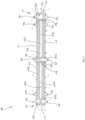
- Body 110 has an inner surface defining a cavity 150 within body 110.
- a strong draw solution chamber 130 is disposed within cavity 150, at one of proximal end portion 112 or the distal end portion 114.
- Strong draw solution chamber 130 is in fluid communication with strong draw solution inlet 120 for receiving strong draw solution stream 140.
- Strong draw solution chamber 130 is configured to receive strong draw solution stream 140 and to provide and/or direct flow of strong draw solution stream 140 to semipermeable membranes 152.
- strong draw solution chamber 130 is configured to be in fluid communication with strong draw solution outlet 132, such that a portion of strong draw solution stream 140 may bypass semipermeable membranes 152 to flow out of forward osmosis membrane vessel 100 without contacting feed stream 142.
- Forward osmosis membrane vessel 100 includes at least two semipermeable membranes 152 (e.g., first semipermeable membrane 152a and second semipermeable membrane 152b) disposed within the cavity of body 110.
- first semipermeable membrane 152a and second semipermeable membrane 152b e.g., first semipermeable membrane 152a and second semipermeable membrane 152b
- forward osmosis membrane vessel 100 may be configured to include more than two semipermeable membranes, such as three semipermeable membranes, four semipermeable membranes, five semipermeable membranes, or at least six semipermeable membranes.
- the semipermeable membranes 152 include a feed side for receiving feed stream 142 comprising a feed solute and a draw side for receiving strong draw solution stream 140 comprising a draw solute.
- Strong draw solution stream 140 may have an osmotic pressure that is equal to or greater than the osmotic pressure of feed stream 142. In some embodiments, however, strong draw solution stream 140 has an osmotic pressure that is less than that of the feed stream 142, such that diffusion of solvent (e.g., water) from feed stream 142 through semipermeable membrane 152 is assisted with a pressure that is greater on the feed side than on the draw side.
- the osmotic pressure of strong draw solution stream 140 is substantially equal to or equal to the osmotic pressure of feed stream 142.
- Semipermeable membranes 152 are configured to produce diluted draw solution stream 144 and brine stream 146.
- first semipermeable membrane 152a produces a first diluted draw solution stream 144a and a first brine stream 146a while second semipermeable membrane 152b produces a second diluted draw solution stream 144b and a second brine stream 146b.
- Semipermeable membranes 152 may be configured to have a first end 154, a second end 155 spaced from the first end 154, and an inner surface 156 delineating a passageway 158 extending from first end 154 to second end 155. As illustrated in FIG.
- Forward osmosis membrane vessel 100 includes a brine chamber 160 in fluid communication with brine stream outlet 162 and configured for receiving brine stream 146.
- Brine chamber 160 receives brine streams 146 produced from each of semipermeable membranes 152 directly or indirectly.
- brine chamber 160 is disposed at least partially between first semipermeable membrane 152a and second semipermeable membrane 152b to directly receive brine stream 146a produced from first semipermeable membrane 152a and second brine stream 146b produced from second semipermeable membrane 152b.
- forward osmosis membrane vessel 100 includes solely one brine stream outlet 162. Additionally or alternatively, forward osmosis membrane vessel 100 may include a brine inlet 164 that is in fluid communication with brine chamber 160.
- a central core manifold 134 is positioned within brine chamber 160.
- Central core manifold 134 extends from passageway 158a of first semipermeable membrane 152a to second passageway 158b of second semipermeable membrane 152b, such that strong draw solution stream 140 may flow through brine chamber 160 without mixing with brine stream 146 therein.
- the semipermeable membranes 152 may be adapted for cross-flow filtration, whereby strong draw solution stream 140 flows in a radial direction from inner surface 156 to the outer surface of semipermeable membrane 152, while feed stream 140 flows in an axial direction from first end 154 to second end 155 of semipermeable membranes 152.
- the feed solute and/or feed particles (e.g., salt, ion, metal, etc.) of feed stream 140 may pass through semipermeable membrane 152 in an axial direction, while the draw solute and/or draw solute particles of strong draw solution stream 140 pass through semipermeable membrane 152 in a radial direction.
- Forward osmosis membrane vessel 100 is configured such that semipermeable membranes 152 operate in parallel.
- feed stream 142 may enter forward osmosis membrane vessel 100 through first feed stream inlet 124 located at proximal end portion 112 and second feed stream inlet 126 located at distal end portion 114.
- Feed stream 142b flowing through second stream inlet 126 may flow to feed stream chamber 136 and subsequently second semipermeable membrane 152b.
- Feed stream 142a flowing through first feed stream inlet 124 flows through an aperture that extends through strong draw solution chamber 130, such that feed stream 142a flows into first semipermeable membrane 152a without mixing with strong draw solution stream 140 within strong draw solution chamber 130.
- Strong draw solution stream 140 may enter forward osmosis membrane vessel 100 by way of strong draw solution inlet 120 and flow into strong draw solution chamber 130 and subsequently to passageway 158 extending through semipermeable membranes 152.
- Central core manifold 134 is disposed within brine chamber 160 to transfer strong draw solution stream 140 flowing through passageway 158a of first semipermeable membrane 152a to second passageway 158b of second semipermeable membrane 152b.
- first and second semipermeable membranes 152a and 152b may operate in parallel and receive strong draw solution stream 140 from a continuous passageway 158 that flows through brine chamber 160, which is positioned between first semipermeable membrane 152 and second permeable membrane 152b.
- strong draw solution stream 140 passes through semipermeable membrane 152 in an axial direction from the semipermeable membrane 152a to the semipermeable membrane 152b and back to the semipermeable membrane 152a and exit through strong draw solution outlet 132.
- a portion of strong draw solution stream 140 flows in a radial direction and bypasses semipermeable membranes 152 and pulls water from feed stream 142 in a radial direction to form diluted draw solution stream 144 in a space between the inner surface of the body and the outer surface of the semipermeable membranes and to produce brine stream 146 from feed stream 142.
- Diluted draw solution stream 144a produced from semipermeable membrane 152a may be collected in the space between the inner surface of the body and the outer surface of the semipermeable membrane 152a, as illustrated in FIG. 2 , and then pass from the space through diluted draw solution outlet 122a, while diluted draw solution stream 144b produced from semipermeable membrane 152b may be collected in the space between the inner surface of the body and the outer surface of the semipermeable membrane 152b, as illustrated in FIG. 2 , and then exit from the space through diluted draw solution outlet 122b.
- Brine stream 146a produced from semipermeable membrane 152a and brine stream 146b produce from semipermeable membrane 152b flow into a single brine chamber 160 and may flow out of forward osmosis membrane vessel 100 via brine stream outlet 162.
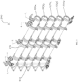
- Forward osmosis membrane vessel 100 is configured to be stackable, such that a plurality of forward osmosis membrane vessels 100 may be assembled to form a forward osmosis membrane vessel stack, as further discussed below.
- brine chamber 160 and strong draw solution chamber 130 of first forward osmosis membrane vessel 100 aligns with brine chamber 160 and strong draw solution chamber 130 of an adjacent second forward osmosis membrane vessel 100.
- the plurality of forward osmosis membrane vessels 100 of forward osmosis membrane vessel stack 200 may be assembled such that brine chamber 160 and strong draw solution chamber 130 of a first forward osmosis membrane vessel 100a align with brine
- Forward osmosis membrane vessel stack 200 may be configured such that the plurality of forward osmosis membrane vessels 100 may be in fluid communication and/or coupled.
- Each of the plurality of forward osmosis membrane vessels 100 may be coupled directly (e.g., an aperture of first forward osmosis membrane vessel 100a may be attached to an aperture of adjacent second forward osmosis membrane vessel 100b) or indirectly (e.g., an outlet of first forward osmosis membrane vessel 100a may be coupled to an inlet of adjacent second forward osmosis membrane vessel 100b via tubes, pipes, etc.) to an adjacent forward osmosis membrane vessel 100.
- brine stream outlet 162 of first forward osmosis membrane vessel 100a may be in fluid communication with brine stream inlet 164 of adjacent second forward osmosis membrane vessel 100b.
- brine stream outlet 162 of first forward osmosis membrane vessel 100a is connected (e.g., by attachment of adjacent apertures) to brine stream inlet 164 of adjacent second forward osmosis membrane vessel 100b.
- Strong draw solution outlet 132 of first forward osmosis membrane vessel 100a may be in fluid communication with strong draw solution inlet 120 of adjacent second forward osmosis membrane vessel 100b.
- strong draw solution outlet 132 of first forward osmosis membrane vessel 100a is connected (e.g., by attachment of adjacent apertures) to strong draw solution inlet 120 of adjacent second forward osmosis membrane vessel 100b.
- Diluted draw solution outlet 122 of first osmosis vessel 100a may be in fluid communication with diluted draw solution inlets 123 of second adjacent forward osmosis membrane vessel 100b.
- diluted draw solution outlet 122 of first osmosis vessel 100a may be connected (e.g., by attachment of adjacent apertures) to diluted draw solution inlets 123 of second adjacent forward osmosis membrane vessel 100b.
- the apertures forming strong draw solution outlet 132, brine stream outlet 162, diluted draw solution outlet 122, and feed stream outlet 128 of first forward osmosis membrane vessel 100a are be configured to directly connect (e.g., by attachment of adjacent apertures) to the strong draw solution inlet 120, brine stream inlet 164, diluted draw solution inlet 123, and feed stream inlet 124 of adjacent second forward osmosis membrane vessel 100b, respectively.
- Forward osmosis membrane vessel stack 200 may be configured such that each of the plurality of forward osmosis membrane vessels 100 operate in parallel.
- Forward osmosis membrane vessel stack 200 may include a single distribution pipe 212 for distributing feed stream 142a to first feed stream inlet 124 of each of the plurality of forward osmosis membrane vessels 100.
- forward osmosis membrane vessel stack 200 may be configured such that providing a single one of the plurality of forward osmosis membrane vessels 100 with a strong draw stream 140 provides each of the plurality of forward osmosis membrane vessels 100 with strong draw stream 140 and enables the plurality of forward osmosis membrane vessels 100, and semipermeable membranes 152 therein, to operate in parallel.
- Diluted draw solution stream 144 and brine stream 146 produced from all of the plurality of forward osmosis membrane vessels 100 may be removed and/or collected from outlets (e.g., diluted draw solution outlet 122 and/or brine outlet 162) of a single forward osmosis membrane vessel 100e.
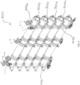
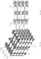
- FIGS. 6A and 6B depict a plurality of forward osmosis membrane vessel stacks 200 coupled together. Although the embodiments illustrated in FIGS. 6A and 6B include four forward osmosis membrane vessel stacks 200, more than four or less than four forward osmosis membrane vessel stacks 200 may be included.
- One of ordinary skill in the art would understand how to affix two or more forward osmosis membrane vessel stacks 200 adjacent to each other, e.g., using one or more straps, saddles, support frames, and hardware.
- a support frame 214 may be used for securing the forward osmosis membrane vessel stacks 200 in a relative position with respect to each other.
- FIG. 7 depicts another exemplary, non-limiting embodiment of a forward osmosis membrane vessel not according to the claims.
- Forward osmosis membrane vessel 300 operates similar to forward osmosis membrane vessel 100 and includes similar features and/or elements, which may be omitted for brevity from the description below. It should be understood that although similar features and/or elements may be employed, various aspects of forward osmosis membrane vessel 300, e.g., size, shape, material, etc., may be different than those described with respect to forward osmosis membrane vessel 100.
- forward osmosis membrane vessel 300 includes a body 310 defining a cavity 350 and at least two semipermeable membranes 352 disposed within cavity 350. Unlike forward osmosis membrane vessel 100, forward osmosis membrane vessel 300 includes a first feed stream inlet 324 and a second feed stream inlet 326 that extend through end bases 316 and 318 of body 310.
- Body 310 has a proximal end portion 312 and a distal end portion 314 spaced from proximal end portion 312.
- Body 310 may form a cylindrical shape having a first base end 316, a second base end 318, and a side wall 317 extending between first base end 316 and second base end 318.
- Body 310 is configured to include a plurality of inlets and outlets, which may be formed by one or more apertures.
- Body 310 defines at least a strong draw solution inlet 320, a diluted draw solution outlet 322, a first feed stream inlet 324, a second feed stream inlet 326, and a brine stream outlet 362 each formed by a separate aperture extending through body 310. As illustrated by the embodiment shown in FIG.
- forward osmosis membrane vessel 300 does not include a feed stream chamber or a feed stream outlet.
- FIG. 9 depicts a forward osmosis membrane vessel stack 400 according to another aspect not according to the invention.
- Forward osmosis membrane vessel stack 400 is similar to forward osmosis membrane vessel stack 200, but includes a plurality of at least two forward osmosis membrane vessels 300 in a stacked configuration.
- FIG. 9 illustrates a plurality of five forward osmosis membrane vessels 300a-300e in a stacked configuration
- forward osmosis membrane vessel stack 400 may include three, four, six, seven, eight, nine, or at least ten forward osmosis membrane vessels 300 in a stacked configuration.
- Forward osmosis membrane vessel stack 400 includes two distribution pipes 412a and 412b for distributing a feed stream to first and second feed stream inlets 324 and 326 of each of the plurality of forward osmosis membrane vessels 300.
- FIGS. 10A and 10B depict a plurality of forward osmosis membrane vessel stacks 400 coupled together.
- the embodiments illustrated in FIGS. 10A and 10B include four forward osmosis membrane vessel stacks 400, more than four or less than four forward osmosis membrane vessel stacks 400 may be included.
- One of ordinary skill in the art would understand how to affix two or more forward osmosis membrane vessel stacks 400 adjacent to each other, e.g., using one or more straps, saddles, support frames, and hardware.
- a support frame 214 may be used for securing the forward osmosis membrane vessel stacks 400 in a relative position with respect to each other.
- FIGS. 11 and 12 depict yet a further non-limiting, exemplary embodiment of a forward osmosis membrane vessel 500 in accordance with an aspect of the disclosure.
- Forward osmosis membrane vessel 500 operates similar to forward osmosis membrane vessels 100 and 300 and includes similar features and/or elements, which may be omitted for brevity from the description below. It should be understood that although similar features and/or elements may be employed, various aspects of forward osmosis membrane vessel 500, e.g., size, shape, material, etc., may be different than those described with respect to forward osmosis membrane vessels 100 and/or 300.
- forward osmosis membrane vessel 500 includes a body 510 defining a cavity 550 and at least two semipermeable membranes 552 disposed within cavity 550. Unlike forward osmosis membrane vessels 100 and 300, forward osmosis membrane vessel 500 includes a first feed stream inlet 524 and a second feed stream inlet 526 that extend through side wall 517 of body 510. Additionally, forward osmosis membrane vessel 500 may have all inlets and outlets for receiving a stream extending through side wall 517 of body 510. For instance, forward osmosis membrane vessel 500 may be configured to not have any inlets or outlet extending through base end 516 or 518.
- Body 510 has a proximal end portion 512 and a distal end portion 514 spaced from proximal end portion 512.
- Body 510 may form a cylindrical shape having a first base end 516, a second base end 518, and a side wall 517 extending between first base end 516 and second base end 518.
- Body 510 is configured to include a plurality of inlets and outlets, which may be formed by one or more apertures.
- Body 510 defines at least a strong draw solution inlet 520, a diluted draw solution outlet 522, a first feed stream inlet 524, a second feed stream inlet 526, and a brine stream outlet 562 each be formed by a separate aperture extending from body 510.
- strong draw solution inlet 520, diluted draw solution outlet 522, and brine stream outlet 562 first feed stream inlet 524, and second feed stream inlet 526 extend through side wall 517.
- Forward osmosis membrane vessel 500 includes at least two feed stream chambers 536a and 536b. As depicted by FIG. 12 , feed stream 142 may enter forward osmosis membrane vessel 500 through first feed stream inlet 524 located at proximal end portion 512 and second feed stream inlet 526 located at distal end portion 514. Feed streams 142a and 142b flowing through first and second feed stream inlets 524 and 526, respectively, may flow into feed stream chambers 536a and 536b, respectively. From feed stream chambers 536a and 536b, feed stream 142a and 142b flow to semipermeable membranes 552a and 552b, respectively.
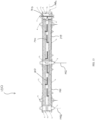
- FIGS. 13 and 14 depict a cross-sectional view of forward osmosis membrane vessel 100 of FIG. 1 with arrows to indicate exemplary flow paths of streams therein.
- forward osmosis membrane vessel 100 may be operated with stream flow paths that are different from those illustrated in FIG. 2 .
- the elements of forward osmosis membrane vessel 100 have been labeled with the same reference numerals, although the stream flow paths of one or more of the strong draw solution stream 140, feed stream 142, diluted draw solution stream 144, and the brine stream 146 are different from those depicted in FIG. 2 .
- feed stream 142 may enter forward osmosis membrane vessel 100 through brine outlet 162 and flow to brine chamber 160. From brine chamber 160, feed stream 142 may flow into first and second semipermeable membranes 152a and 152b. Brine streams 144a and 144b, produced respectively from first semipermeable membrane 152a and second semipermeable membrane 152b, may flow out of forward osmosis membrane vessel 100 through first feed inlet 124 and second feed inlet 126. As shown in FIG. 13 , brine stream 146b collects in feed chamber 136 prior to flowing out of forward osmosis membrane vessel 100 through second feed inlet 126.
- strong draw solution stream 140 enters forward osmosis membrane vessel 100 through diluted draw solution inlets 123a and 123b and flows into the space defined between semipermeable membranes 152 and the inner surface defining cavity 150. Strong draw solution 140 subsequently flows through semipermeable membranes 152 in a radial direction inward toward passageway 158. As strong draw solution 140 flows through semipermeable membranes 152, diluted draw solution stream 144 is produced and collected in passageway 158 defined by the inner surface 156 of semipermeable membranes 152.
- Diluted draw solution stream 144 flows to and/or collects in strong draw solution chamber 130 prior to flowing out of forward osmosis membrane vessel 100 through strong draw solution outlet 132.
- Feed stream 142 and brine stream 146 may have a flow path through forward osmosis membrane vessel 100 similar to that depicted in FIG. 13 .
Landscapes
- Engineering & Computer Science (AREA)
- Water Supply & Treatment (AREA)
- Chemical & Material Sciences (AREA)
- Chemical Kinetics & Catalysis (AREA)
- Life Sciences & Earth Sciences (AREA)
- Hydrology & Water Resources (AREA)
- Environmental & Geological Engineering (AREA)
- Organic Chemistry (AREA)
- Separation Using Semi-Permeable Membranes (AREA)
Claims (9)
- Vorwärtsosmose-Membranbehälter (100, 100a-e, 200a-d, 300a-e, 400a-d), der zum Stapeln konfiguriert ist, umfassend:- ein Gehäuse (110) mit einem proximalen Endabschnitt (112) und einem distalen Endabschnitt (114), der von dem proximalen Endabschnitt beabstandet ist, wobei das Gehäuse darin einen Hohlraum (150) definiert und einen Einlass (120) für starke Ziehlösung, einen Auslass (132) für starke Ziehlösung, einen Einlass (123) für verdünnte Ziehlösung, einen Auslass (122) für verdünnte Ziehlösung, einen am proximalen Endabschnitt (112) angeordneten ersten Zulaufstromeinlass (124), einen am distalen Endabschnitt (114) angeordneten zweiten Zulaufstromeinlass (126), einen Soleeinlass (164) und einen Soleauslass (162) abgrenzt, wobei der Einlass (120) für starke Ziehlösung, der Auslass (132) für starke Ziehlösung, der Einlass (123) für verdünnte Ziehlösung, der Auslass (122) für verdünnte Ziehlösung, der zweite Zulaufstromeinlass (126), der Soleeinlass (164) und der Soleauslass (162) in einer Seitenwand (117) des Gehäuses (110) ausgebildet sind,- eine Kammer (130) für starke Ziehlösung, die innerhalb des Hohlraums am proximalen Endabschnitt oder am distalen Endabschnitt angeordnet ist, wobei die Kammer für starke Ziehlösung in Fluidverbindung mit dem Einlass für starke Ziehlösung steht, um einen Strom starker Ziehlösung (140) aufzunehmen,- eine erste und eine zweite halbdurchlässige Membran (152a, 152b), die jeweils in dem Hohlraum des Gehäuses angeordnet sind und zur Vorwärtsosmosefiltration konfiguriert sind, wobei die erste und die zweite halbdurchlässige Membran jeweils eine Zulaufseite zum Annehmen eines Zulaufstroms (142) mit einem Zulaufsolut und eine Abziehseite zum Annehmen des Stroms starker Ziehlösung mit einem Ziehsolut umfasst, wobei die erste und die zweite semipermeable Membran einen Strom verdünnter Ziehlösung (144) erzeugen, die erste und die zweite semipermeable Membran einen ersten Solestrom (146a) bzw. einen zweiten Solestrom (146b) erzeugen, wobei die erste semipermeable Membran und die zweite semipermeable Membran jeweils zylindrisch mit einem Durchgang (158) sind, der sich in axialer Richtung durch sie hindurch erstreckt, wobei die Kammer (130) für starke Ziehlösung den ersten Zulaufstromeinlass (124) umfasst, der durch eine Öffnung gebildet wird, die sich durch die Kammer (130) für starke Ziehlösung hindurch erstreckt, so dass der Zulaufstrom (142), der durch den ersten Zulaufstromeinlass (124) fließt, und der Strom (140) starker Ziehlösung nicht vermischt werden,- eine Zulaufstromkammer (136), die innerhalb des Hohlraums am proximalen Endabschnitt oder am distalen Endabschnitt gegenüber der Kammer (130) für starke Ziehlösung angeordnet ist, wobei die Zulaufstromkammer in Fluidverbindung mit dem ersten Zulaufstromeinlass oder dem zweiten Zulaufstromeinlass steht,- eine Solekammer (160), die zumindest teilweise zwischen der ersten semipermeablen Membran (152a) und der zweiten semipermeablen Membran (152b) angeordnet ist, wobei die Solekammer in Fluidverbindung mit dem Soleeinlass und dem Soleauslass steht, wobei die Solekammer in Fluidverbindung mit der ersten semipermeablen Membran steht, um den ersten Solestrom aufzunehmen, und in Fluidverbindung mit der zweiten semipermeablen Membran steht, um den zweiten Solestrom aufzunehmen, und- einen zentralen Kernverteiler (134), der sich durch die Solekammer (160) erstreckt, wobei der zentrale Kernverteiler so konfiguriert ist, dass er die starke Ziehlösung durch den Durchgang der ersten semipermeablen Membran zu dem Durchgang der zweiten semipermeablen Membran ohne Vermischung mit dem ersten und zweiten Solestrom überführt,- wobei der Raum zwischen der Innenfläche des Gehäuses und der Außenfläche der ersten und der zweiten halbdurchlässigen Membran in Fluidverbindung mit dem Auslass für verdünnte Ziehlösung steht und so konfiguriert ist, dass er den Strom verdünnter Ziehlösung aufnimmt,- wobei der Vorwärtsosmose-Membranbehälter (100, 100a-e, 200a-d, 300a-e, 400a-d) so konfiguriert ist, dass er stapelbar ist, wobei der Soleauslass eines ersten Vorwärtsosmose-Membranbehälters mit dem Soleeinlass eines benachbarten zweiten Vorwärtsosmose-Membranbehälters (100a-e, 200a-d, 300a-e, 400a-d) verbunden ist, wobei der Auslass für die starke Ziehlösung des ersten Vorwärtsosmose-Membranbehälters mit dem Einlass für die starke Ziehlösung des benachbarten zweiten Vorwärtsosmose-Membranbehälters verbunden ist, so dass in einer gestapelten Konfiguration die Solekammer und die Kammer für starke Ziehlösung des Vorwärtsosmose-Membranbehälters mit der Solekammer und der Kammer für starke Ziehlösung des benachbarten zweiten Vorwärtsosmose-Membranbehälters (100a-e, 200a-d, 300a-e, 400a-d) fluchten.
- Stapel von Vorwärtsosmose-Membranbehältern, der eine Vielzahl von Vorwärtsosmose-Membranbehältern nach Anspruch 1 umfasst, wobei die Vielzahl von Vorwärtsosmose-Membranbehältern (100a-e, 200a-d, 300a-e, 400a-d) mindestens einen ersten Vorwärtsosmose-Membranbehälter in gestapelter Konfiguration mit einem benachbarten zweiten Vorwärtsosmose-Membranbehälter umfasst, wobei die Solekammer und die Kammer für starke Ziehlösung des ersten Vorwärtsosmose-Membranbehälters mit der Solekammer und der Kammer für starke Ziehlösung des benachbarten zweiten Vorwärtsosmose-Membranbehälters fluchten.
- Stapel von Vorwärtsosmose-Membranbehältern nach Anspruch 2, wobei der Soleauslass des ersten Vorwärtsosmose-Membranbehälters mit dem Soleeinlass des benachbarten zweiten Vorwärtsosmose-Membranbehälters durch Verbinden des Soleauslasses des ersten Vorwärtsosmose-Membranbehälters mit dem Soleeinlass des benachbarten zweiten Vorwärtsosmose-Membranbehälters in Fluidverbindung steht.
- Stapel von Vorwärtsosmose-Membranbehältern nach Anspruch 2, wobei der Auslass für die starke Ziehlösung des ersten Vorwärtsosmose-Membranbehälters in Fluidverbindung mit dem Einlass für die starke Ziehlösung des benachbarten zweiten Vorwärtsosmose-Membranbehälters steht, indem der Auslass für die starke Ziehlösung des ersten Vorwärtsosmose-Membranbehälters mit dem Einlass für die starke Ziehlösung des benachbarten zweiten Vorwärtsosmose-Membranbehälters verbunden wird.
- Stapel von Vorwärtsosmose-Membranbehältern nach Anspruch 2, wobei der Auslass für verdünnte Ziehlösung des ersten Vorwärtsosmose-Membranbehälters in Fluidverbindung mit dem Einlass für verdünnte Ziehlösung des benachbarten zweiten Vorwärtsosmose-Membranbehälters steht, indem der Auslass für verdünnte Ziehlösung des ersten Vorwärtsosmose-Membranbehälters mit dem Einlass für verdünnte Ziehlösung des benachbarten zweiten Vorwärtsosmose-Membranbehälters verbunden wird.
- Vorwärtsosmose-Membranbehälter nach Anspruch 1, wobei die Zulaufstromkammer in Fluidverbindung mit einem Zulaufstromauslass steht, um zu ermöglichen, dass ein Teil des Zulaufstroms die erste und die zweite semipermeable Membran umgeht und ausfließt, ohne mit der starken Ziehlösung in Kontakt zu kommen.
- Vorwärtsosmose-Membranbehälter nach Anspruch 1, wobei das Gehäuse eine erste Stirnseite (116) und eine zweite Stirnseite (118) aufweist und die Seitenwand (117) sich zwischen erster Stirnseite und zweiter Stirnseite erstreckt.
- Vorwärtsosmose-Membranbehälter nach Anspruch 1, wobei der Gehäuse eine zylindrische Konfiguration mit einer umlaufenden Seitenwand aufweist, die sich zwischen der ersten Stirnseite und der zweiten Stirnseite erstreckt.
- Vorwärtsosmose-Membranbehälter nach Anspruch 1, wobei der Behälter einen einzigen Solestromauslass aufweist.
Applications Claiming Priority (2)
| Application Number | Priority Date | Filing Date | Title |
|---|---|---|---|
| US201962885100P | 2019-08-09 | 2019-08-09 | |
| PCT/US2020/045457 WO2021030205A1 (en) | 2019-08-09 | 2020-08-07 | Stackable forward osmosis membrane vessel with side ports |
Publications (3)
| Publication Number | Publication Date |
|---|---|
| EP4010288A1 EP4010288A1 (de) | 2022-06-15 |
| EP4010288A4 EP4010288A4 (de) | 2023-08-09 |
| EP4010288B1 true EP4010288B1 (de) | 2025-06-25 |
Family
ID=74570365
Family Applications (1)
| Application Number | Title | Priority Date | Filing Date |
|---|---|---|---|
| EP20851896.9A Active EP4010288B1 (de) | 2019-08-09 | 2020-08-07 | Stapelbarer vorwärts-osmose-membranbehälter mit seitlichen anschlüssen |
Country Status (4)
| Country | Link |
|---|---|
| US (1) | US12390766B2 (de) |
| EP (1) | EP4010288B1 (de) |
| SA (1) | SA522431636B1 (de) |
| WO (1) | WO2021030205A1 (de) |
Families Citing this family (2)
| Publication number | Priority date | Publication date | Assignee | Title |
|---|---|---|---|---|
| US20240189773A1 (en) * | 2021-04-23 | 2024-06-13 | Waterise As | A filter-box and a retrievable subsea filter module with a filter-box |
| WO2025155962A2 (en) * | 2024-01-18 | 2025-07-24 | Jennifer Ross | Fluid exchange chamber for light sheet imaging and scattering |
Family Cites Families (13)
| Publication number | Priority date | Publication date | Assignee | Title |
|---|---|---|---|---|
| US8083942B2 (en) * | 2004-12-06 | 2011-12-27 | Board of Regents of the Nevada System of Higher Education, on Behalf of the Universary of Nevada, Reno | Systems and methods for purification of liquids |
| WO2010020253A1 (en) | 2008-08-21 | 2010-02-25 | Grundfos Management A/S | A forward osmosis device |
| CA2779607A1 (en) | 2009-06-08 | 2010-12-16 | Hydration Systems, Llc | Osmotic pump for forward osmosis devices |
| KR20140064853A (ko) * | 2011-08-10 | 2014-05-28 | 오아시스 워터, 인크. | 열 및 질량 전달을 위한 판 및 프레임 및 나선형으로 감긴 멤브레인 모듈 |
| KR101966761B1 (ko) | 2012-02-24 | 2019-04-08 | 도레이 카부시키가이샤 | 분리막 엘리먼트 및 분리막 모듈 |
| SG10201707727UA (en) | 2012-12-21 | 2017-10-30 | Porifera Inc | Separation systems, elements, and methods for separation utilizing stacked membranes and spacers |
| US20140224716A1 (en) | 2013-02-08 | 2014-08-14 | Oasys Water, Inc. | Osmotic separation systems and methods |
| PE20151711A1 (es) | 2013-03-15 | 2015-11-18 | Oasys Water Inc | Modulos de membrana |
| US20150014248A1 (en) * | 2013-07-15 | 2015-01-15 | Hydration Systems, Llc | Method and system for generating strong brines |
| JP6609042B2 (ja) | 2015-09-30 | 2019-11-20 | ダウ グローバル テクノロジーズ エルエルシー | 螺旋巻きモジュール、塩水シール、及び端キャップを含むフィルタアセンブリ |
| KR102190050B1 (ko) | 2016-08-04 | 2020-12-14 | 오아시스 워터 엘엘씨 | 정삼투 시스템의 성능을 개선하기 위한 시스템 및 방법 |
| WO2018034153A1 (ja) | 2016-08-18 | 2018-02-22 | 東洋紡株式会社 | 平型中空糸膜モジュールおよび膜分離ユニット |
| JP6972737B2 (ja) | 2017-07-28 | 2021-11-24 | 東洋紡株式会社 | 中空糸膜モジュール |
-
2020
- 2020-08-07 US US17/634,209 patent/US12390766B2/en active Active
- 2020-08-07 WO PCT/US2020/045457 patent/WO2021030205A1/en not_active Ceased
- 2020-08-07 EP EP20851896.9A patent/EP4010288B1/de active Active
-
2022
- 2022-02-09 SA SA522431636A patent/SA522431636B1/ar unknown
Also Published As
| Publication number | Publication date |
|---|---|
| US20220288533A1 (en) | 2022-09-15 |
| EP4010288A1 (de) | 2022-06-15 |
| US12390766B2 (en) | 2025-08-19 |
| WO2021030205A1 (en) | 2021-02-18 |
| SA522431636B1 (ar) | 2025-05-21 |
| EP4010288A4 (de) | 2023-08-09 |
Similar Documents
| Publication | Publication Date | Title |
|---|---|---|
| US8216474B2 (en) | Systems and methods for purification of liquids | |
| JP5992998B2 (ja) | 浸透分離システムおよび方法 | |
| AU2015244268B2 (en) | Osmotic separation systems and methods | |
| US8029671B2 (en) | Combined membrane-distillation-forward-osmosis systems and methods of use | |
| CN102958848B (zh) | 利用膜蒸馏法的正向渗透脱盐装置 | |
| US10904968B2 (en) | Water treatment methods | |
| US9278872B2 (en) | Process for operating a cooling tower comprising the treatment of feed water by direct osmosis | |
| US20130233797A1 (en) | Methods for osmotic concentration of hyper saline streams | |
| van Linden et al. | Separation of natural organic matter and sodium chloride for salt recovery purposes in zero liquid discharge | |
| Chen et al. | Membrane filtration | |
| US9908801B2 (en) | Elimination of sodium sulfate from biologically treated wastewater | |
| US12390766B2 (en) | Stackable forward osmosis membrane vessel with side ports | |
| WO2018195534A1 (en) | Hollow fiber membrane module for direct contact membrane distillation-based desalinization | |
| Abdel-Fatah et al. | Industrial wastewater treatment by membrane process | |
| Wang et al. | Understand the basics of membrane filtration | |
| Abdel-Fatah et al. | and Nanofiltration Membrane Applications | |
| Cheng et al. | Use of nanofiltration membranes to concentrate and recover leached aluminum from acidified water treatment sludge | |
| Lipnizki | Strategies for controlling membrane fouling | |
| Matsuura et al. | Jiaping Paul Chen, Honghui Mou, Lawrence K. Wang | |
| WO2025187237A1 (ja) | 浄化水の製造方法、及びシリカスケールリスクの低減方法 | |
| ES2779982A1 (es) | Sistema y metodo para la concentracion de soluciones salinas acuosas con recuperacion de agua |
Legal Events
| Date | Code | Title | Description |
|---|---|---|---|
| STAA | Information on the status of an ep patent application or granted ep patent |
Free format text: STATUS: THE INTERNATIONAL PUBLICATION HAS BEEN MADE |
|
| PUAI | Public reference made under article 153(3) epc to a published international application that has entered the european phase |
Free format text: ORIGINAL CODE: 0009012 |
|
| STAA | Information on the status of an ep patent application or granted ep patent |
Free format text: STATUS: REQUEST FOR EXAMINATION WAS MADE |
|
| 17P | Request for examination filed |
Effective date: 20220303 |
|
| AK | Designated contracting states |
Kind code of ref document: A1 Designated state(s): AL AT BE BG CH CY CZ DE DK EE ES FI FR GB GR HR HU IE IS IT LI LT LU LV MC MK MT NL NO PL PT RO RS SE SI SK SM TR |
|
| DAV | Request for validation of the european patent (deleted) | ||
| DAX | Request for extension of the european patent (deleted) | ||
| A4 | Supplementary search report drawn up and despatched |
Effective date: 20230712 |
|
| RIC1 | Information provided on ipc code assigned before grant |
Ipc: B01D 63/12 20060101ALI20230706BHEP Ipc: C02F 1/00 20060101ALI20230706BHEP Ipc: B01D 61/00 20060101ALI20230706BHEP Ipc: B01D 69/04 20060101ALI20230706BHEP Ipc: B01D 61/58 20060101ALI20230706BHEP Ipc: C02F 1/44 20060101AFI20230706BHEP |
|
| STAA | Information on the status of an ep patent application or granted ep patent |
Free format text: STATUS: EXAMINATION IS IN PROGRESS |
|
| 17Q | First examination report despatched |
Effective date: 20240319 |
|
| GRAP | Despatch of communication of intention to grant a patent |
Free format text: ORIGINAL CODE: EPIDOSNIGR1 |
|
| STAA | Information on the status of an ep patent application or granted ep patent |
Free format text: STATUS: GRANT OF PATENT IS INTENDED |
|
| INTG | Intention to grant announced |
Effective date: 20250127 |
|
| GRAS | Grant fee paid |
Free format text: ORIGINAL CODE: EPIDOSNIGR3 |
|
| GRAA | (expected) grant |
Free format text: ORIGINAL CODE: 0009210 |
|
| STAA | Information on the status of an ep patent application or granted ep patent |
Free format text: STATUS: THE PATENT HAS BEEN GRANTED |
|
| AK | Designated contracting states |
Kind code of ref document: B1 Designated state(s): AL AT BE BG CH CY CZ DE DK EE ES FI FR GB GR HR HU IE IS IT LI LT LU LV MC MK MT NL NO PL PT RO RS SE SI SK SM TR |
|
| REG | Reference to a national code |
Ref country code: GB Ref legal event code: FG4D |
|
| REG | Reference to a national code |
Ref country code: CH Ref legal event code: EP |
|
| REG | Reference to a national code |
Ref country code: CH Ref legal event code: EP |
|
| REG | Reference to a national code |
Ref country code: IE Ref legal event code: FG4D |
|
| REG | Reference to a national code |
Ref country code: DE Ref legal event code: R096 Ref document number: 602020053467 Country of ref document: DE |
|
| PG25 | Lapsed in a contracting state [announced via postgrant information from national office to epo] |
Ref country code: FI Free format text: LAPSE BECAUSE OF FAILURE TO SUBMIT A TRANSLATION OF THE DESCRIPTION OR TO PAY THE FEE WITHIN THE PRESCRIBED TIME-LIMIT Effective date: 20250625 |
|
| PGFP | Annual fee paid to national office [announced via postgrant information from national office to epo] |
Ref country code: DE Payment date: 20250820 Year of fee payment: 6 |
|
| REG | Reference to a national code |
Ref country code: LT Ref legal event code: MG9D |
|
| PG25 | Lapsed in a contracting state [announced via postgrant information from national office to epo] |
Ref country code: NO Free format text: LAPSE BECAUSE OF FAILURE TO SUBMIT A TRANSLATION OF THE DESCRIPTION OR TO PAY THE FEE WITHIN THE PRESCRIBED TIME-LIMIT Effective date: 20250925 Ref country code: GR Free format text: LAPSE BECAUSE OF FAILURE TO SUBMIT A TRANSLATION OF THE DESCRIPTION OR TO PAY THE FEE WITHIN THE PRESCRIBED TIME-LIMIT Effective date: 20250926 |
|
| PG25 | Lapsed in a contracting state [announced via postgrant information from national office to epo] |
Ref country code: BG Free format text: LAPSE BECAUSE OF FAILURE TO SUBMIT A TRANSLATION OF THE DESCRIPTION OR TO PAY THE FEE WITHIN THE PRESCRIBED TIME-LIMIT Effective date: 20250625 |
|
| PGFP | Annual fee paid to national office [announced via postgrant information from national office to epo] |
Ref country code: GB Payment date: 20250815 Year of fee payment: 6 |
|
| PG25 | Lapsed in a contracting state [announced via postgrant information from national office to epo] |
Ref country code: HR Free format text: LAPSE BECAUSE OF FAILURE TO SUBMIT A TRANSLATION OF THE DESCRIPTION OR TO PAY THE FEE WITHIN THE PRESCRIBED TIME-LIMIT Effective date: 20250625 |
|
| PG25 | Lapsed in a contracting state [announced via postgrant information from national office to epo] |
Ref country code: RS Free format text: LAPSE BECAUSE OF FAILURE TO SUBMIT A TRANSLATION OF THE DESCRIPTION OR TO PAY THE FEE WITHIN THE PRESCRIBED TIME-LIMIT Effective date: 20250925 |
|
| PG25 | Lapsed in a contracting state [announced via postgrant information from national office to epo] |
Ref country code: LV Free format text: LAPSE BECAUSE OF FAILURE TO SUBMIT A TRANSLATION OF THE DESCRIPTION OR TO PAY THE FEE WITHIN THE PRESCRIBED TIME-LIMIT Effective date: 20250625 |
|
| REG | Reference to a national code |
Ref country code: NL Ref legal event code: MP Effective date: 20250625 |
|
| PG25 | Lapsed in a contracting state [announced via postgrant information from national office to epo] |
Ref country code: NL Free format text: LAPSE BECAUSE OF FAILURE TO SUBMIT A TRANSLATION OF THE DESCRIPTION OR TO PAY THE FEE WITHIN THE PRESCRIBED TIME-LIMIT Effective date: 20250625 |
|
| PG25 | Lapsed in a contracting state [announced via postgrant information from national office to epo] |
Ref country code: PT Free format text: LAPSE BECAUSE OF FAILURE TO SUBMIT A TRANSLATION OF THE DESCRIPTION OR TO PAY THE FEE WITHIN THE PRESCRIBED TIME-LIMIT Effective date: 20251027 |
|
| REG | Reference to a national code |
Ref country code: AT Ref legal event code: MK05 Ref document number: 1806329 Country of ref document: AT Kind code of ref document: T Effective date: 20250625 |
|
| PG25 | Lapsed in a contracting state [announced via postgrant information from national office to epo] |
Ref country code: IS Free format text: LAPSE BECAUSE OF FAILURE TO SUBMIT A TRANSLATION OF THE DESCRIPTION OR TO PAY THE FEE WITHIN THE PRESCRIBED TIME-LIMIT Effective date: 20251025 |
|
| PG25 | Lapsed in a contracting state [announced via postgrant information from national office to epo] |
Ref country code: AT Free format text: LAPSE BECAUSE OF FAILURE TO SUBMIT A TRANSLATION OF THE DESCRIPTION OR TO PAY THE FEE WITHIN THE PRESCRIBED TIME-LIMIT Effective date: 20250625 Ref country code: SM Free format text: LAPSE BECAUSE OF FAILURE TO SUBMIT A TRANSLATION OF THE DESCRIPTION OR TO PAY THE FEE WITHIN THE PRESCRIBED TIME-LIMIT Effective date: 20250625 |
|
| PG25 | Lapsed in a contracting state [announced via postgrant information from national office to epo] |
Ref country code: CZ Free format text: LAPSE BECAUSE OF FAILURE TO SUBMIT A TRANSLATION OF THE DESCRIPTION OR TO PAY THE FEE WITHIN THE PRESCRIBED TIME-LIMIT Effective date: 20250625 |
|
| PG25 | Lapsed in a contracting state [announced via postgrant information from national office to epo] |
Ref country code: PL Free format text: LAPSE BECAUSE OF FAILURE TO SUBMIT A TRANSLATION OF THE DESCRIPTION OR TO PAY THE FEE WITHIN THE PRESCRIBED TIME-LIMIT Effective date: 20250625 |
|
| PG25 | Lapsed in a contracting state [announced via postgrant information from national office to epo] |
Ref country code: EE Free format text: LAPSE BECAUSE OF FAILURE TO SUBMIT A TRANSLATION OF THE DESCRIPTION OR TO PAY THE FEE WITHIN THE PRESCRIBED TIME-LIMIT Effective date: 20250625 |
|
| PG25 | Lapsed in a contracting state [announced via postgrant information from national office to epo] |
Ref country code: SK Free format text: LAPSE BECAUSE OF FAILURE TO SUBMIT A TRANSLATION OF THE DESCRIPTION OR TO PAY THE FEE WITHIN THE PRESCRIBED TIME-LIMIT Effective date: 20250625 |
|
| PG25 | Lapsed in a contracting state [announced via postgrant information from national office to epo] |
Ref country code: ES Free format text: LAPSE BECAUSE OF FAILURE TO SUBMIT A TRANSLATION OF THE DESCRIPTION OR TO PAY THE FEE WITHIN THE PRESCRIBED TIME-LIMIT Effective date: 20250625 |
|
| PG25 | Lapsed in a contracting state [announced via postgrant information from national office to epo] |
Ref country code: RO Free format text: LAPSE BECAUSE OF FAILURE TO SUBMIT A TRANSLATION OF THE DESCRIPTION OR TO PAY THE FEE WITHIN THE PRESCRIBED TIME-LIMIT Effective date: 20250625 |
|
| REG | Reference to a national code |
Ref country code: CH Ref legal event code: H13 Free format text: ST27 STATUS EVENT CODE: U-0-0-H10-H13 (AS PROVIDED BY THE NATIONAL OFFICE) Effective date: 20260324 |
|
| REG | Reference to a national code |
Ref country code: DE Ref legal event code: R097 Ref document number: 602020053467 Country of ref document: DE |
|
| PG25 | Lapsed in a contracting state [announced via postgrant information from national office to epo] |
Ref country code: MC Free format text: LAPSE BECAUSE OF FAILURE TO SUBMIT A TRANSLATION OF THE DESCRIPTION OR TO PAY THE FEE WITHIN THE PRESCRIBED TIME-LIMIT Effective date: 20250625 |
|
| PG25 | Lapsed in a contracting state [announced via postgrant information from national office to epo] |
Ref country code: DK Free format text: LAPSE BECAUSE OF FAILURE TO SUBMIT A TRANSLATION OF THE DESCRIPTION OR TO PAY THE FEE WITHIN THE PRESCRIBED TIME-LIMIT Effective date: 20250625 |
|
| PG25 | Lapsed in a contracting state [announced via postgrant information from national office to epo] |
Ref country code: LU Free format text: LAPSE BECAUSE OF NON-PAYMENT OF DUE FEES Effective date: 20250807 Ref country code: IT Free format text: LAPSE BECAUSE OF FAILURE TO SUBMIT A TRANSLATION OF THE DESCRIPTION OR TO PAY THE FEE WITHIN THE PRESCRIBED TIME-LIMIT Effective date: 20250625 |
|
| PG25 | Lapsed in a contracting state [announced via postgrant information from national office to epo] |
Ref country code: CH Free format text: LAPSE BECAUSE OF NON-PAYMENT OF DUE FEES Effective date: 20250831 |
|
| PLBE | No opposition filed within time limit |
Free format text: ORIGINAL CODE: 0009261 |
|
| STAA | Information on the status of an ep patent application or granted ep patent |
Free format text: STATUS: NO OPPOSITION FILED WITHIN TIME LIMIT |
|
| REG | Reference to a national code |
Ref country code: CH Ref legal event code: L10 Free format text: ST27 STATUS EVENT CODE: U-0-0-L10-L00 (AS PROVIDED BY THE NATIONAL OFFICE) Effective date: 20260507 |