EP4010282B1 - Anschlussvorrichtung zur herstellung einer fluidischen verbindung zwischen einem vorratsbehälter und einer anderen fluidischen vorrichtung und entsprechendes ringelement zur codierung des speicherbehälters - Google Patents
Anschlussvorrichtung zur herstellung einer fluidischen verbindung zwischen einem vorratsbehälter und einer anderen fluidischen vorrichtung und entsprechendes ringelement zur codierung des speicherbehälters Download PDFInfo
- Publication number
- EP4010282B1 EP4010282B1 EP19755854.7A EP19755854A EP4010282B1 EP 4010282 B1 EP4010282 B1 EP 4010282B1 EP 19755854 A EP19755854 A EP 19755854A EP 4010282 B1 EP4010282 B1 EP 4010282B1
- Authority
- EP
- European Patent Office
- Prior art keywords
- connection apparatus
- storage container
- connection
- coding
- ring element
- Prior art date
- Legal status (The legal status is an assumption and is not a legal conclusion. Google has not performed a legal analysis and makes no representation as to the accuracy of the status listed.)
- Active
Links
Images


Classifications
-
- B—PERFORMING OPERATIONS; TRANSPORTING
- B67—OPENING, CLOSING OR CLEANING BOTTLES, JARS OR SIMILAR CONTAINERS; LIQUID HANDLING
- B67D—DISPENSING, DELIVERING OR TRANSFERRING LIQUIDS, NOT OTHERWISE PROVIDED FOR
- B67D7/00—Apparatus or devices for transferring liquids from bulk storage containers or reservoirs into vehicles or into portable containers, e.g. for retail sale purposes
- B67D7/06—Details or accessories
- B67D7/32—Arrangements of safety or warning devices; Means for preventing unauthorised delivery of liquid
- B67D7/34—Means for preventing unauthorised delivery of liquid
- B67D7/344—Means for preventing unauthorised delivery of liquid by checking a correct coupling or coded information
-
- B—PERFORMING OPERATIONS; TRANSPORTING
- B67—OPENING, CLOSING OR CLEANING BOTTLES, JARS OR SIMILAR CONTAINERS; LIQUID HANDLING
- B67D—DISPENSING, DELIVERING OR TRANSFERRING LIQUIDS, NOT OTHERWISE PROVIDED FOR
- B67D7/00—Apparatus or devices for transferring liquids from bulk storage containers or reservoirs into vehicles or into portable containers, e.g. for retail sale purposes
- B67D7/02—Apparatus or devices for transferring liquids from bulk storage containers or reservoirs into vehicles or into portable containers, e.g. for retail sale purposes for transferring liquids other than fuel or lubricants
- B67D7/0288—Container connection means
Definitions
- the invention relates to a connection apparatus for establishing a fluidic connection between a storage container and another fluidic device.
- the invention further relates to a system with an aforementioned connection apparatus and a ring element for coding a storage container and a kit of parts for establishing such systems.
- a connection apparatus for establishing a fluidic connection between a storage container and another fluidic device like a dispensing device is known from document US 9090450 B2 .
- This document describes a dispensing assembly with a connection unit for establishing a fluidic connection between a storage container and the dispensing assembly, the connection unit comprising: (i) an extracting probe for extracting liquid from said storage container; (ii) a connection part for connecting the rest of the dispensing assembly; and (iii) a support in form of an insert component for mounting a container outlet of the storage container on the connection unit such that the extracting probe extends into the container outlet, wherein the insert component has a spatial coding structure for forming a joint of interlocking parts together with a spatially compatible counter-coding structure on the upper part of a cap capping the container outlet, wherein only spatially compatible coding structures of connection apparatus and ring element permit the storage container to be mounted on the dispensing assembly.
- EP 3 326 579 A1 refers to a Container for storing a cleaning or care medium with a coding element for distinguishing between such containers and a method for producing such a container.
- US 2011/309114 A1 refers to a connecting device for ensuring proper connection of liquid containers is provided.
- the connecting device comprises a bottle closure having a dip tube passage and a first key code pattern at the top.
- US 9 090 450 B2 refers to a method and device to ensure that a particular dispensing packagecan only be engaged into an appropriate dispensing location.
- EP 0 890 546 A1 refers to a Device for connecting at least a discharge tube and return tube to a bung connection of a container for liquids and the like, said connection being embodied with inner screw thread
- said device comprises: a cylindrical insert with screw thread arranged on the cylinder outer wall and co-acting with the bung, and a bottom provided with at least two openings, a tube connecting bung provided with passages for the discharge tube and return tube aligned with said openings, and a clamping piece for fixing the connecting bung in the cylindrical insert via connecting means, wherein there are arranged lugs placed in a determined pattern and recesses receiving these lugs, wherein the clamping piece is connected non-slidably in axial direction to the bung but freely rotatable relative thereto, and wherein the connecting means in the insert are arranged at a distance from the bottom in order to form a chamber, the recesses are placed above the chamber in the insert and the lugs lie on a downward extended part of the clamping piece and
- WO 2014/085701 A1 refers to a two-part key coded device that can be added to existing container and dispense stations.
- the key coded device includes a female key ring that is retrofitted to an existing bung and a compatible male key ring that is retrofitted to an existing or new dispense head.
- connection apparatuses are intended for mounting on the storage container and are intended for specific liquids only.
- one object underlying the present invention is to provide measures to prevent confusion and mistakes when mounting such a connection apparatus for a specific liquid on a storage container.
- the connection apparatus for extracting liquid from a storage container comprises: (i) an extracting probe for extracting liquid from said storage container; (ii) a connection piece for connecting the other fluidic device; and (iii) a support for mounting the connection apparatus on a container outlet of the storage container such that the extracting probe extends into the container outlet, wherein the support has a spatial coding structure for forming a joint of interlocking parts together with a spatially compatible counter-coding structure of a ring element embracing the container outlet, wherein only spatially compatible coding structures of connection apparatus and ring element permit the apparatus to be mounted on the storage container; wherein the spatial coding structure is a crown-like protrusion-recess structure for forming a joint of interlocking parts together with a protrusion-recess structure of the spatially suitable counter-coding structure of the ring element; and wherein the crown-like protrusion-recess structure includes two protrusions that are axially extending and two recesses.
- the coding of the crown-like protrusion-recess structure is given by the form and/or arrangement of the protrusions and recesses of said protrusion-recess structure.
- connection apparatus further comprises a marking corresponding to the spatial coding structure, which is clearly visible in operation of the connection apparatus.
- the marking is preferably located at the top of the connection apparatus.
- the marking especially is a colour marking.
- the marking might comprise more than one colour, but preferably the marking comprises only one colour.
- the extracting probe comprises a hollow needle for penetrating a membrane at the container outlet, wherein said hollow needle forms a channel though which liquid flows when extracting the liquid from the storage container.
- connection apparatus further comprises a check-valve in a liquid path between the extracting probe and the connection piece.
- the invention further relates to a system according to claim 7.
- the invention finally relates to a kit of parts according to claim 10.
- Fig. 1 shows an overall arrangement of a storage container 10 for fluids and a system 12 with a connection apparatus 14 for establishing a fluidic connection between the storage container 10 and another fluidic device (not shown) and a corresponding ring element 16 for coding the storage container 10.
- the fluid storage container 10 is formed as a canister 18 with a container outlet 20 (explicitly shown in Figs. 6 and 13 ) and a handle 22.
- the system 12 is mounted on said container outlet 20 (whereby this outlet 20 is not visible in Fig. 1 ).
- the ring element 16 is fastened to the container outlet 20 such that the ring element 16 embraces the container outlet 20.
- the connection apparatus 14 comprises a main body 24, a connection piece 26 for connecting the other fluidic device and a support 28 for mounting the connection apparatus 14 on the container outlet 20 of the storage container 10.
- the support 28 has a spatial coding structure 30 for forming a joint of interlocking parts together with a spatially compatible counter-coding structure 32 (visible in Figs. 6 and 9 to 12 ) of the ring element 16 in such way that only spatially compatible coding structures 30, 32 of connection apparatus 14 and ring element 16 permit the connection apparatus 14 to be mounted on the container outlet 20 (the parts interact in a similar way to key and lock).
- a spatial coding structure 30 for forming a joint of interlocking parts together with a spatially compatible counter-coding structure 32 (visible in Figs. 6 and 9 to 12 ) of the ring element 16 in such way that only spatially compatible coding structures 30, 32 of connection apparatus 14 and ring element 16 permit the connection apparatus 14 to be mounted on the container outlet 20 (the parts interact in a similar way to key and lock).
- Each of the elements 14, 16 of the system 12 for ensuring a desired combination of storage container 10 and connection apparatus 14, namely the connection apparatus 14 itself and the ring element 16, is labeled with a marking 34,
- Fig. 2 shows the overall arrangement of a storage container 10 and the system 12 with the connection apparatus 14 and the corresponding ring element 16, wherein coding and counter coding structures 30, 32 fit together and the connection apparatus 14 is mounted on the container outlet 20.
- the counter-coding structure 32 coats the coding structure.
- the ring element 16 can be understood as a spacer for the installation of the connection apparatus 14 on the container outlet 20. If the coding/counter coding structures 30, 32 do not fit together, the ring element 16 acts as the spacer and prevents the fluidic connection. Furthermore, a ventilation opening 38 of the container 10 is visible in Fig. 2 .
- Fig. 3 shows the connection apparatus 14 in a cutaway (sectional) 3d view.
- the connection apparatus 14 further comprises an 40 for extracting liquid from said storage container 10 and a check-valve 42 in a liquid path between the extracting probe 40 and the connection piece 26.
- the check-valve 42 is located in the center of the main body 24 and comprises a spring 47 and a ball 48 as a valve member.
- the extracting probe 40 comprises a hollow needle 44 for penetrating a membrane (shown e.g. in fig.
- connection apparatus 14 extracts liquid from the storage container 10 the liquid flows through the hollow needle 44, the check-valve 42 and the connection piece 26.
- the main body 24 of the connection apparatus is made of plastic.
- Fig. 4 shows the connection apparatus 14 in a sectional view. Extracting probe 40 and check-valve 42 form a single component 40, 42. This single component 40, 42 is - as well as the connection piece 26 pressed into the main body 24.
- Fig. 5 shows the connection apparatus 14 in an upside down presentation. In this presentation two protrusions 50 and two recesses 52 of the coding structure 30 are visible.
- the coding structure 30 therefore might be called a crown-like protrusion-recess structure 54.
- the crown-like protrusion-recess structure 54 is interacting with the coding structure 32 of the ring element 16, which is a corresponding crown-like protrusion-recess structure 56 (shown in fig. 6 ).
- Fig. 6 shows the storage container 10 and the ring element 16 for coding the storage container 10 surrounding the container outlet 20.
- an insert component 58 or a head of a suction lance, respectively
- the counter-coding structure 32 of the ring element 16 comprises two protrusions 62 and two recesses 64 of the counter-coding structure 32.
- the counter-coding structure 32 therefore might be called a crown-like protrusion-recess structure 56.
- Each of the recesses 64 has the form of a semicircular slot in which the protrusion 52 of the corresponding coding structure 30 can engage.
- the ring element 16 further comprises nose structures 66 for a detachable clip- on connection between connection apparatus 14 and ring element 16 as well as snapper elements 68 for establishing a snap-fit connection for fastening the ring element 16 to the container outlet 20.
- the snapper elements 68 are interacting with an external screw thread 70 of the container outlet 20.
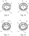
- Figures 9 to 12 are showing ring elements 16 with different spatial counter-coding structures 32. These different spatial counter-coding structures 32 are associated with a colour code given by table 1. The colour code is used for the marking 34 executed as label and the marking 36 executed as material colour of the ring element 16. TABLE 1: coding table specifying the correlation between the coding structure and the colour code coding 1 protrusion 2 protrusions 3 protrusions 2 protrusions structure (symmetrical) (symmetrical) (asymmetrical) colour code red green yellow grey
- Fig. 10 shows a ring element16 comprising a spatial counter-coding structure 32 with two protrusions 62 arranged opposite to each other. According to table 1 this spatial counter-coding structure 32 is linked to the colour green of the colour marking.
- Fig. 12 shows a ring element16 comprising a spatial counter-coding structure 32 with two asymmetrically arranged protrusions 62. According to table 1 this spatial counter-coding structure 32 is linked to the colour grey of the colour marking.
- Fig. 13 shows another overall arrangement of the storage container 10 and the system 12 with the connection apparatus 14 and the ring element 16 shown in figs. 1 and 2 ;
- Fig. 14 shows the container outlet 20 and parts of the storage container 10 in the surrounding of the container outlet 20 together with the connection apparatus 14 and the ring element 16 in a sectional view.
- the mounting of the connection apparatus 14 to the container outlet 20 is blocked by the ring element 16 because the spatial coding structure 30 of the connection apparatus 14 and the spatial counter-coding structure 32 of the ring element 16 do not fit.
- the hollow needle 44 does not penetrate the membrane 60 in the container outlet 20 through which the liquid flows when extracting the liquid from the storage container 10.
Landscapes
- Engineering & Computer Science (AREA)
- Mechanical Engineering (AREA)
- Details Of Rigid Or Semi-Rigid Containers (AREA)
Claims (12)
- Verbindungseinrichtung (14) zum Herstellen einer Fluidverbindung zwischen einem Lagerbehälter (10) und einer anderen Fluidvorrichtung, die Verbindungseinrichtung (14) umfassend:eine Extraktionssonde (40) zum Extrahieren von Flüssigkeit aus dem Lagerbehälter (10);ein Verbindungsstück (26) zum Verbinden der anderen Fluidvorrichtung; undeine Halterung (28) zum Anbringen der Verbindungseinrichtung (14) an einem Behälterauslass (20) des Lagerbehälters (10) derart, dass die Extraktionssonde (40) sich in den Behälterauslass (20) erstreckt,wobei der Träger (28) eine Ortskodierungsstruktur (30) zum Ausbilden einer Verbindungsstelle aus formschlüssigen Teilen zusammen mit einer örtlich kompatiblen Gegenkodierungsstruktur (32) eines den Behälterauslass (20) umgreifenden Ringelements (16) aufweist, wobei nur örtlich kompatible Kodierungsstrukturen (30, 32) von der Verbindungseinrichtung (14) und dem Ringelement (16) es ermöglichen, dass die Verbindungseinrichtung (14) an dem Lagerbehälter (10) angebracht wird;wobei die Ortskodierungsstruktur (30) eine kronenartige Vorsprung-Vertiefungs-Struktur (54) zum Ausbilden einer Verbindungsstelle aus formschlüssigen Teilen zusammen mit einer Vorsprung-Vertiefungs-Struktur (56) der örtlich passenden Gegenkodierungsstruktur (32) des Ringelements (16) ist; undwobei die kronenartige Vorsprung-Vertiefungs-Struktur (54) zwei Vorsprünge (50), die sich axial erstrecken, und zwei Vertiefungen (52) einschließt.
- Verbindungseinrichtung nach Anspruch 1, wobei die Kodierung der kronenartigen Vorsprung-Vertiefungs-Struktur (54) durch die Form und/oder die Anordnung der Vorsprünge (50) und der Vertiefungen (52) dieser Vorsprung-Vertiefungs-Struktur (54) gegeben ist.
- Verbindungseinrichtung nach Anspruch 1 oder 2, ferner umfassend eine der Ortskodierungsstruktur (30) entsprechende systematische Markierung (34), die bei einem Betrieb der Verbindungseinrichtung (14) deutlich sichtbar ist.
- Verbindungseinrichtung nach Anspruch 3, wobei die Markierung (34) eine Farbmarkierung ist.
- Verbindungseinrichtung nach einem der Ansprüche 1 bis 4, wobei die Extraktionssonde (40) eine Hohlnadel (44) zum Durchstechen einer Membran (60) in dem Behälterauslass (20) umfasst, durch die die Flüssigkeit fließt, wenn die Flüssigkeit aus dem Lagerbehälter (10) extrahiert wird.
- Verbindungseinrichtung nach einem der Ansprüche 1 bis 5, ferner umfassend ein Rückschlagventil (42) in einem Flüssigkeitspfad zwischen der Extraktionssonde (40) und dem Verbindungsstück (26).
- System (12) zum Sicherstellen einer gewünschten Kombination aus Lagerbehälter (10) und Verbindungseinrichtung (14), wenn die Verbindungseinrichtung (14) zum Herstellen einer Fluidverbindung zwischen dem Lagerbehälter (10) und einer anderen Fluidvorrichtung verwendet wird, das System (12) umfassend die Verbindungseinrichtung (14) nach Anspruch 1 bis 5 und ein Ringelement (16) zum Kodieren des Lagerbehälters (10), wobei das Ringelement (16) an dem Behälterauslass (20) des Lagerbehälters (10) derart befestigbar ist, dass das Ringelement (16) den Behälterauslass (20) umschließt, wobei das Ringelement (16) eine Ortsgegenkodierstruktur (32) zum Ausbilden einer Verbindungsstelle aus formschlüssigen Teilen zusammen mit der örtlich kompatiblen Kodierungsstruktur (30) der Verbindungseinrichtung (14) aufweist, die an dem Behälterauslass (20) angebracht werden kann.
- System nach Anspruch 7, wobei das Ringelement (16) ferner eine systematische Markierung (36), insbesondere eine Farbmarkierung, die bei dem Betrieb der Verbindungseinrichtung (14) deutlich sichtbar ist, umfasst, wobei die Markierung (36) der Ortsgegenkodierungsstruktur (32) entspricht.
- System nach Anspruch 7, wobei das Ringelement (16) ferner mindestens ein Schnappelement (68) zum Herstellen einer Schnappverbindung zum Befestigen des Ringelements (16) an dem Behälterauslass (20) umfasst.
- Kit aus Teilen zum Herstellen von Systemen (12) zum Sicherstellen einer gewünschten Kombination aus Lagerbehälter (10) und Verbindungseinrichtung (14), wenn die Verbindungseinrichtung (14) zum Herstellen einer Fluidverbindung zwischen dem Lagerbehälter (10) und einer anderen Fluidvorrichtung verwendet wird, das Kit umfassend eine Anzahl von Verbindungseinrichtungen (14) nach Anspruch 1 bis 6 mit verschiedenen Ortskodierungsstrukturen (30) und einer Anzahl von Ringelementen (16) zum Kodieren des Lagerbehälters (10), der an dem Behälterauslass (20) des Lagerbehälters (10) derart befestigbar ist, dass das Ringelement (16) den Behälterauslass (20) umschließen kann, wobei die Ringelemente (16) eine Ortsgegenkodierstruktur (32) zum Ausbilden einer Verbindungsstelle aus formschlüssigen Teilen zusammen mit der örtlich kompatiblen Kodierungsstruktur (30) der Verbindungseinrichtung (14) aufweisen, die an dem Behälterauslass (20) angebracht werden kann.
- Kit nach Anspruch 10, wobei die Ringelemente (16) ferner eine systematische Markierung (36), insbesondere eine Farbmarkierung, die bei dem Betrieb der Verbindungseinrichtung (14) deutlich sichtbar ist, umfasst, wobei die Markierung (36) der Ortsgegenkodierungsstruktur (32) entspricht.
- Kit nach Anspruch 10, wobei die Ringelemente (16) ferner mindestens ein Schnappelement (68) zum Herstellen einer Schnappverbindung zum Befestigen der Ringelemente (16) an dem Behälterauslass (20) umfassen.
Priority Applications (1)
| Application Number | Priority Date | Filing Date | Title |
|---|---|---|---|
| PL19755854.7T PL4010282T3 (pl) | 2019-08-09 | 2019-08-09 | Urządzenie łączące do utworzenia połączenia płynowego między pojemnikiem magazynowym a innym urządzeniem płynowym oraz odpowiedni element pierścieniowy do kodowania pojemnika magazynowego |
Applications Claiming Priority (1)
| Application Number | Priority Date | Filing Date | Title |
|---|---|---|---|
| PCT/EP2019/071512 WO2021028013A1 (en) | 2019-08-09 | 2019-08-09 | Connection apparatus for establishing a fluidic connection between a storage container and another fluidic device and a corresponding ring element for coding the storage container |
Publications (3)
| Publication Number | Publication Date |
|---|---|
| EP4010282A1 EP4010282A1 (de) | 2022-06-15 |
| EP4010282B1 true EP4010282B1 (de) | 2025-07-02 |
| EP4010282C0 EP4010282C0 (de) | 2025-07-02 |
Family
ID=67667828
Family Applications (1)
| Application Number | Title | Priority Date | Filing Date |
|---|---|---|---|
| EP19755854.7A Active EP4010282B1 (de) | 2019-08-09 | 2019-08-09 | Anschlussvorrichtung zur herstellung einer fluidischen verbindung zwischen einem vorratsbehälter und einer anderen fluidischen vorrichtung und entsprechendes ringelement zur codierung des speicherbehälters |
Country Status (6)
| Country | Link |
|---|---|
| US (1) | US12258260B2 (de) |
| EP (1) | EP4010282B1 (de) |
| AU (1) | AU2019461478B2 (de) |
| ES (1) | ES3037084T3 (de) |
| PL (1) | PL4010282T3 (de) |
| WO (1) | WO2021028013A1 (de) |
Family Cites Families (10)
| Publication number | Priority date | Publication date | Assignee | Title |
|---|---|---|---|---|
| US5957328A (en) * | 1992-09-11 | 1999-09-28 | Now Technologies, Inc. | Liquid chemical dispensing and recirculating system |
| NL1006510C2 (nl) | 1997-07-08 | 1999-01-12 | Wiva Bv | Inrichting voor het verbinden van althans een afvoer- en retourbuis aan een aansluitstomp van een vloeistofvat. |
| US6015068A (en) * | 1998-02-04 | 2000-01-18 | Now Technologies, Inc. | Liquid chemical dispensing system with a key code ring for connecting the proper chemical to the proper attachment |
| US6412666B1 (en) * | 2001-03-19 | 2002-07-02 | International Business Machines Corporation | Fluid container with a keying means to prevent improper fluid loading in a fluid delivery tool and a system including such fluid container and fluid delivery tool |
| AU2006327107B2 (en) | 2005-12-22 | 2011-07-28 | Diversey, Inc. | Lock-out device and method |
| JP3914560B1 (ja) * | 2006-01-31 | 2007-05-16 | 東京応化工業株式会社 | 流体容器用の継手 |
| US8302813B2 (en) * | 2010-06-16 | 2012-11-06 | Chun-Hung Chen | High efficiency chemical connecting device and liquid chemical dispensing system using the same |
| JP2013545676A (ja) * | 2010-10-15 | 2013-12-26 | アドバンスド テクノロジー マテリアルズ,インコーポレイテッド | ライナーをベースとする分配容器のためのコネクタ |
| KR102164155B1 (ko) | 2012-11-29 | 2020-10-12 | 엔테그리스, 아이엔씨. | 키 코드를 가지는 일회용 디스펜스 헤드 |
| EP3326579B1 (de) * | 2016-11-23 | 2019-07-03 | W & H Dentalwerk Bürmoos GmbH | Behälter zur lagerung eines reinigungs- oder pflegemediums mit kodierelement zur unterscheidung solcher behälter sowie verfahren zur herstellung eines solchen behälters |
-
2019
- 2019-08-09 WO PCT/EP2019/071512 patent/WO2021028013A1/en not_active Ceased
- 2019-08-09 EP EP19755854.7A patent/EP4010282B1/de active Active
- 2019-08-09 ES ES19755854T patent/ES3037084T3/es active Active
- 2019-08-09 PL PL19755854.7T patent/PL4010282T3/pl unknown
- 2019-08-09 AU AU2019461478A patent/AU2019461478B2/en active Active
-
2022
- 2022-02-09 US US17/650,421 patent/US12258260B2/en active Active
Also Published As
| Publication number | Publication date |
|---|---|
| WO2021028013A1 (en) | 2021-02-18 |
| EP4010282C0 (de) | 2025-07-02 |
| US20220162055A1 (en) | 2022-05-26 |
| AU2019461478A1 (en) | 2022-03-03 |
| AU2019461478B2 (en) | 2024-01-04 |
| US12258260B2 (en) | 2025-03-25 |
| ES3037084T3 (en) | 2025-09-26 |
| EP4010282A1 (de) | 2022-06-15 |
| PL4010282T3 (pl) | 2025-08-18 |
Similar Documents
| Publication | Publication Date | Title |
|---|---|---|
| US6817390B2 (en) | Keyed anesthetic vaporizer filling system | |
| US5862961A (en) | Connection device for dispensing fluid from a bottle | |
| US7735692B2 (en) | Rotating dispenser head with locking and venting closure connector for an air foaming pump dispenser | |
| JP4308898B2 (ja) | 誤動作防止手段を有する、機械への流体供給用組立品 | |
| EP3210644B1 (de) | Vorrichtungen zur einrastung einer ventil- und druckbehälteranordnung mit schulter | |
| EP2057403B1 (de) | Schieberventilansatz und bund | |
| US9862588B2 (en) | Fitment for dispensing fluids from a flexible container | |
| US20080083784A1 (en) | Rotating Collar and Locking and Venting Closure Connector for an Air Foaming Pump Dispenser | |
| KR101373900B1 (ko) | 멀티레이트 튜브 유동 제한기 | |
| US6202717B1 (en) | Dispensing bottle closure | |
| JP2009528088A (ja) | 麻酔噴霧器のためのアダプタ | |
| US6796343B2 (en) | Fluid dispensing and measuring systems | |
| KR20120009423A (ko) | 용시 혼합 용기 | |
| EP1968883B1 (de) | Verriegelungsvorrichtung und -verfahren | |
| JP2018100128A (ja) | 再充填不能エアロゾル弁 | |
| US6321948B1 (en) | Tap and valve assembly | |
| CN103596698B (zh) | 固定环以及使用这种环的流体制品分配器 | |
| US20160152404A1 (en) | Fluid dispensing apparatus and method | |
| EP4010282B1 (de) | Anschlussvorrichtung zur herstellung einer fluidischen verbindung zwischen einem vorratsbehälter und einer anderen fluidischen vorrichtung und entsprechendes ringelement zur codierung des speicherbehälters | |
| EP1938053A2 (de) | Flüssigkeitsabgabepumpe mit flüssigkeitsverschiebungskolben | |
| EP0605696B1 (de) | Kupplungsvorrichtung | |
| US7497356B2 (en) | Fluid dispenser device | |
| GB2421690A (en) | Filling system for an anaesthetic vaporiser | |
| EP0768275A1 (de) | Verbindungseinrichtung für das Adaptieren einer Dosiervorrichtung an einer Flasche | |
| US20080237268A1 (en) | Leak proof fragrance bottle |
Legal Events
| Date | Code | Title | Description |
|---|---|---|---|
| STAA | Information on the status of an ep patent application or granted ep patent |
Free format text: STATUS: UNKNOWN |
|
| STAA | Information on the status of an ep patent application or granted ep patent |
Free format text: STATUS: THE INTERNATIONAL PUBLICATION HAS BEEN MADE |
|
| PUAI | Public reference made under article 153(3) epc to a published international application that has entered the european phase |
Free format text: ORIGINAL CODE: 0009012 |
|
| STAA | Information on the status of an ep patent application or granted ep patent |
Free format text: STATUS: REQUEST FOR EXAMINATION WAS MADE |
|
| 17P | Request for examination filed |
Effective date: 20220208 |
|
| AK | Designated contracting states |
Kind code of ref document: A1 Designated state(s): AL AT BE BG CH CY CZ DE DK EE ES FI FR GB GR HR HU IE IS IT LI LT LU LV MC MK MT NL NO PL PT RO RS SE SI SK SM TR |
|
| DAV | Request for validation of the european patent (deleted) | ||
| DAX | Request for extension of the european patent (deleted) | ||
| STAA | Information on the status of an ep patent application or granted ep patent |
Free format text: STATUS: EXAMINATION IS IN PROGRESS |
|
| 17Q | First examination report despatched |
Effective date: 20240612 |
|
| GRAP | Despatch of communication of intention to grant a patent |
Free format text: ORIGINAL CODE: EPIDOSNIGR1 |
|
| STAA | Information on the status of an ep patent application or granted ep patent |
Free format text: STATUS: GRANT OF PATENT IS INTENDED |
|
| RIC1 | Information provided on ipc code assigned before grant |
Ipc: B67D 7/02 20100101ALI20250117BHEP Ipc: B67D 7/34 20100101AFI20250117BHEP |
|
| INTG | Intention to grant announced |
Effective date: 20250207 |
|
| GRAS | Grant fee paid |
Free format text: ORIGINAL CODE: EPIDOSNIGR3 |
|
| GRAA | (expected) grant |
Free format text: ORIGINAL CODE: 0009210 |
|
| STAA | Information on the status of an ep patent application or granted ep patent |
Free format text: STATUS: THE PATENT HAS BEEN GRANTED |
|
| AK | Designated contracting states |
Kind code of ref document: B1 Designated state(s): AL AT BE BG CH CY CZ DE DK EE ES FI FR GB GR HR HU IE IS IT LI LT LU LV MC MK MT NL NO PL PT RO RS SE SI SK SM TR |
|
| REG | Reference to a national code |
Ref country code: GB Ref legal event code: FG4D |
|
| REG | Reference to a national code |
Ref country code: CH Ref legal event code: EP |
|
| REG | Reference to a national code |
Ref country code: DE Ref legal event code: R096 Ref document number: 602019071946 Country of ref document: DE |
|
| REG | Reference to a national code |
Ref country code: IE Ref legal event code: FG4D |
|
| U01 | Request for unitary effect filed |
Effective date: 20250731 |
|
| U07 | Unitary effect registered |
Designated state(s): AT BE BG DE DK EE FI FR IT LT LU LV MT NL PT RO SE SI Effective date: 20250808 |
|
| REG | Reference to a national code |
Ref country code: ES Ref legal event code: FG2A Ref document number: 3037084 Country of ref document: ES Kind code of ref document: T3 Effective date: 20250926 |
|
| PGFP | Annual fee paid to national office [announced via postgrant information from national office to epo] |
Ref country code: ES Payment date: 20250929 Year of fee payment: 7 |
|
| PGFP | Annual fee paid to national office [announced via postgrant information from national office to epo] |
Ref country code: PL Payment date: 20250822 Year of fee payment: 7 |
|
| PGFP | Annual fee paid to national office [announced via postgrant information from national office to epo] |
Ref country code: GB Payment date: 20250828 Year of fee payment: 7 |
|
| PG25 | Lapsed in a contracting state [announced via postgrant information from national office to epo] |
Ref country code: IS Free format text: LAPSE BECAUSE OF FAILURE TO SUBMIT A TRANSLATION OF THE DESCRIPTION OR TO PAY THE FEE WITHIN THE PRESCRIBED TIME-LIMIT Effective date: 20251102 |
|
| PG25 | Lapsed in a contracting state [announced via postgrant information from national office to epo] |
Ref country code: NO Free format text: LAPSE BECAUSE OF FAILURE TO SUBMIT A TRANSLATION OF THE DESCRIPTION OR TO PAY THE FEE WITHIN THE PRESCRIBED TIME-LIMIT Effective date: 20251002 |
|
| U21 | Renewal fee for the european patent with unitary effect paid with additional fee |
Year of fee payment: 7 Effective date: 20251205 |
|
| PG25 | Lapsed in a contracting state [announced via postgrant information from national office to epo] |
Ref country code: HR Free format text: LAPSE BECAUSE OF FAILURE TO SUBMIT A TRANSLATION OF THE DESCRIPTION OR TO PAY THE FEE WITHIN THE PRESCRIBED TIME-LIMIT Effective date: 20250702 |
|
| PG25 | Lapsed in a contracting state [announced via postgrant information from national office to epo] |
Ref country code: GR Free format text: LAPSE BECAUSE OF FAILURE TO SUBMIT A TRANSLATION OF THE DESCRIPTION OR TO PAY THE FEE WITHIN THE PRESCRIBED TIME-LIMIT Effective date: 20251003 |
|
| PG25 | Lapsed in a contracting state [announced via postgrant information from national office to epo] |
Ref country code: CZ Free format text: LAPSE BECAUSE OF FAILURE TO SUBMIT A TRANSLATION OF THE DESCRIPTION OR TO PAY THE FEE WITHIN THE PRESCRIBED TIME-LIMIT Effective date: 20250702 |
|
| PG25 | Lapsed in a contracting state [announced via postgrant information from national office to epo] |
Ref country code: RS Free format text: LAPSE BECAUSE OF FAILURE TO SUBMIT A TRANSLATION OF THE DESCRIPTION OR TO PAY THE FEE WITHIN THE PRESCRIBED TIME-LIMIT Effective date: 20251002 |