EP4010137B1 - Schneidplatte und werkzeug mit einer solchen schneidplatte - Google Patents
Schneidplatte und werkzeug mit einer solchen schneidplatte Download PDFInfo
- Publication number
- EP4010137B1 EP4010137B1 EP20753736.6A EP20753736A EP4010137B1 EP 4010137 B1 EP4010137 B1 EP 4010137B1 EP 20753736 A EP20753736 A EP 20753736A EP 4010137 B1 EP4010137 B1 EP 4010137B1
- Authority
- EP
- European Patent Office
- Prior art keywords
- wall
- cutting edge
- chamfer
- cutting insert
- region
- Prior art date
- Legal status (The legal status is an assumption and is not a legal conclusion. Google has not performed a legal analysis and makes no representation as to the accuracy of the status listed.)
- Active
Links
- 238000005520 cutting process Methods 0.000 title claims description 236
- 238000003754 machining Methods 0.000 claims description 15
- 230000015572 biosynthetic process Effects 0.000 description 19
- 230000007704 transition Effects 0.000 description 8
- 230000001174 ascending effect Effects 0.000 description 5
- 241001136792 Alle Species 0.000 description 4
- 230000000087 stabilizing effect Effects 0.000 description 3
- 238000000034 method Methods 0.000 description 2
- 230000006641 stabilisation Effects 0.000 description 2
- 238000011105 stabilization Methods 0.000 description 2
- 230000001154 acute effect Effects 0.000 description 1
- 230000006835 compression Effects 0.000 description 1
- 238000007906 compression Methods 0.000 description 1
- 230000007423 decrease Effects 0.000 description 1
- 230000000694 effects Effects 0.000 description 1
- 238000002474 experimental method Methods 0.000 description 1
- 238000004519 manufacturing process Methods 0.000 description 1
- 238000007493 shaping process Methods 0.000 description 1
Images


Classifications
-
- B—PERFORMING OPERATIONS; TRANSPORTING
- B23—MACHINE TOOLS; METAL-WORKING NOT OTHERWISE PROVIDED FOR
- B23B—TURNING; BORING
- B23B27/00—Tools for turning or boring machines; Tools of a similar kind in general; Accessories therefor
- B23B27/04—Cutting-off tools
- B23B27/045—Cutting-off tools with chip-breaking arrangements
-
- B—PERFORMING OPERATIONS; TRANSPORTING
- B23—MACHINE TOOLS; METAL-WORKING NOT OTHERWISE PROVIDED FOR
- B23B—TURNING; BORING
- B23B2200/00—Details of cutting inserts
- B23B2200/08—Rake or top surfaces
- B23B2200/086—Rake or top surfaces with one or more grooves
- B23B2200/087—Rake or top surfaces with one or more grooves for chip breaking
-
- B—PERFORMING OPERATIONS; TRANSPORTING
- B23—MACHINE TOOLS; METAL-WORKING NOT OTHERWISE PROVIDED FOR
- B23B—TURNING; BORING
- B23B2200/00—Details of cutting inserts
- B23B2200/24—Cross section of the cutting edge
- B23B2200/242—Cross section of the cutting edge bevelled or chamfered
Definitions
- the present invention relates to a cutting insert for a machining tool.
- the present invention also relates to a tool with such a cutting insert and a tool holder which has at least one cutting insert holder for receiving the cutting insert.
- the cutting insert according to the invention is preferably a cutting insert that can be used for turning operations.
- the cutting insert according to the invention is particularly preferably suitable for plunge-turning operations.
- the cutting area is not only the area of the cutting edges themselves, but also the entire area of the cutting plate, which influences chip formation during machining of the workpiece.
- the cutting area also includes the rake face and the secondary cutting edges.
- the chip-forming properties of the cutting insert should be improved, regardless of whether the entire main cutting edge comes into contact with the workpiece (full cut) or only a portion of the main cutting edge comes into contact with the workpiece (partial cut).
- a feature of the cutting insert according to the invention is the above-mentioned chamfer, which is divided into three sections and extends at least partially around the chip trough.
- the three partial areas of the bevel are all arranged in the same bevel plane, which is oriented obliquely upwards with respect to the longitudinal direction of the cutting area.
- the chamfer plane does not intersect the chip trough.
- the chamfer level lies entirely above the chip trough.
- the chamfer is therefore aligned at a negative rake angle relative to the xy plane. This is why it is also referred to as a negative phase.
- the partial areas of the chamfer adjacent to the two ends of the main cutting edge enable the cutting corners of the cutting plate to be stabilized.
- the second section the chamfer which extends along a large portion of the length of the main cutting edge, also contributes to stabilizing the main cutting edge.
- the negative chamfer therefore stabilizes the main cutting edge over its entire length or over the entire width of the cutting insert.
- the chip trough which adjoins the negative chamfer described.
- chip surfaces are arranged within this chip trough, the geometry of which is crucial for chip formation.
- the chip trough is limited by a wall.
- This wall has five wall areas that directly adjoin one another in ascending order. What is meant here by “ascending order” is that the second wall area adjoins the first wall area, the third wall area adjoins the second wall area, the fourth wall area adjoins the third wall area and the fifth wall area adjoins the fourth wall area.
- the middle, third wall area is divided by the imaginary plane of symmetry into two halves of the same size that are mirror images of one another.
- the first wall area is a mirror image of the fifth wall area and the second wall area is a mirror image of the fourth wall area. All five wall areas are preferably designed as free-form surfaces.
- the profile line of the wall which results from a cut of the wall with an imaginary plane which is aligned orthogonally to the plane of symmetry and runs along the longitudinal direction, has the following properties:
- the first, the third and the fifth sections of this profile line are each designed to be concave .
- the second and fourth sections of the profile line are each designed to be straight or convex. At least one point on the first section of the profile line is at a closer distance from the main cutting edge than all points on the second, third and fourth sections of the profile line. Due to the symmetry properties of the chip trough, at least one point on the fifth section of the profile line is at a smaller distance from the main cutting edge than all points on the second, third and fourth sections of the profile line. Furthermore, everyone has Points on the second and fourth sections of the profile line are a smaller distance from the main cutting edge than all points on the third section of the profile line.
- the third wall area arranged in the middle of the chip trough has the greatest distance from the main cutting edge.
- the two laterally adjacent, further outer, second and fourth wall regions of the chip trough are arranged somewhat closer to the main cutting edge than the third wall region.
- the two outermost wall areas (first and fifth wall areas), however, have the shortest distance from the main cutting edge.
- these distance relationships do not necessarily have to apply to the entire wall area, but at least to one point on each of these wall areas.
- the last-mentioned web grooving differs from the previously mentioned partial-cut grooving in that the portion of the main cutting edge used for machining the workpiece is arranged in the central region of the main cutting edge, preferably symmetrically to the plane of symmetry, during web grooving, whereas the portion used for machining the workpiece
- the main cutting edge in partial cut grooving extends from one end of the main cutting edge to one any point, which preferably lies between the center and the other end of the main cutting edge.
- the cutting insert is typically loaded asymmetrically to the plane of symmetry of the chip trough.
- the first and third portions of the negative chamfer in particular contribute to stabilizing the cutting corners.
- the middle area of the rear wall of the chip trough i.e. the second, third and fourth wall areas, are not loaded, or at least only minimally, during a full cut.
- the second, third and fourth wall areas of the rear wall of the chip trough therefore do not influence the machining during a full cut at all or at least only very slightly.
- the first and third portions of the negative chamfer, together with the first and fifth wall portions of the rear wall of the chip trough contribute to chip tapering during a full cut.
- the chip removed from the workpiece can therefore flow very easily out of the machining groove. This enables the formation of spiral chips with small chip space numbers.
- one of the subregions of the negative chamfer which is located in the area of the corners of the cutting plate (i.e. either the first subregion or the third subregion of the chamfer), is typically loaded.
- an opposite wall area of the rear wall of the chip trough is loaded during a partial cut.
- the functional surfaces for a partial cut are, for example, the first partial area of the negative chamfer together with the fourth wall area of the chip trough or, on the other side, the second partial area of the negative chamfer together with the fourth wall area of the chip trough.
- the wall areas of the chip trough mentioned act as a compensation for the areas of the negative chamfer mentioned. This means that even with a partial cut, the formation of long, spiral chips is minimized. This means that good chip control and a long service life can be achieved even with a partial cut.
- chip formation is essentially influenced by the centrally arranged, third wall area of the rear wall of the chip trough. As already mentioned, this is furthest away from the main cutting edge and concave in comparison to the other wall areas. This means that the removed chips can also be rolled up laterally during web grooving and thus tapered, which in turn promotes chip breakage and avoids long spiral chips.
- the second portion of the negative chamfer which extends along the majority of the main cutting edge, additionally contributes to stabilizing the main cutting edge during web grooving and thus avoids damage to the main cutting edge due to overloading.
- the inventive design of the cutting area of the cutting plate thus leads to very good chip formation properties, regardless of whether the cutting plate is used to machine a full cut, a partial cut or for web grooving.
- all points on the first section of the profile line are at a smaller distance from the main cutting edge than all points on the second, third and fourth sections of the profile line.
- the first wall area of the rear wall of the chip trough is arranged overall closer to the main cutting edge, the second, the third and the fourth wall area of the rear wall of the chip trough. Due to the symmetry properties of the chip trough, this also applies to the fifth wall area.
- all points on the fifth section of the profile line also have a smaller distance from the main cutting edge than all points on the second, third and fourth sections of the profile line
- the wall areas arranged on the very outside have the smallest distance the main cutting edge and the centrally arranged wall area (third wall area) have the greatest distance from the main cutting edge.
- the distances between the intermediate wall areas (second and fourth wall areas) are each larger than the distance between the third wall area and the main cutting edge, but smaller than the distances of the two outer wall areas (first and fifth wall areas) from the main cutting edge.
- the five sections of the profile line each define a curve that is continuous and differentiable.
- the individual sections of the profile line are each preferably free of kinks and without interruption.
- the individual wall areas are preferably kink-free.
- the five wall areas preferably do not merge tangentially into one another. Kinks or edges can arise between the individual wall areas, i.e. at the transition from one wall area to the next.
- the individual wall areas are within the chip trough, i.e. preferably clearly segmented from one another. This also contributes to the stability of the machining process and improves the chip formation properties that result from machining using the cutting insert according to the invention.
- the third section of the profile line is the longest compared to the remaining sections of the profile line.
- the centrally arranged third wall area therefore preferably forms the largest part of the rear wall of the chip trough. This is particularly advantageous for bar grooving processing.
- the second portion of the negative chamfer preferably borders directly on the main cutting edge.
- the first section of the profile line borders directly on the first section of the negative chamfer.
- the fifth section of the profile line in this embodiment borders directly on the third section of the negative chamfer.
- the first wall region of the chip trough borders directly on the first partial region of the negative chamfer and the fifth wall region of the chip trough directly borders on the third partial region of the negative chamfer.
- the first and third portions of the negative chamfer are preferably each designed as a flat surface.
- a first boundary line between the chip trough and the first partial region of the negative chamfer runs at a first angle ⁇ relative to the main cutting edge, viewed in a plan view, where 30° ⁇ ⁇ ⁇ 90°.
- a second boundary line between the chip trough and the second partial region of the negative chamfer runs at a second angle ⁇ 2 relative to the main cutting edge, where ⁇ 2 is the opposite angle to ⁇ .
- elevations are arranged in the chip trough, which protrude upwards from a bottom surface arranged in the chip trough, the elevations being arranged parallel to one another in a row along the main cutting edge.
- the number of increments is preferably odd.
- three, five, seven or nine elevations can be provided along the main cutting edge.
- the elevations are arranged at equal distances from one another along the main cutting edge and parallel to it.
- the elevations border directly on the second portion of the negative chamfer, which extends parallel to the main cutting edge and along a large part of it.
- the elevations each have a surface section that lies in the chamfer plane.
- the negative chamfer merges into the individual elevations in the central area of the main cutting edge, i.e. preferably directly and tangentially. This increases the compression effect exerted on the chip lifted from the workpiece due to the elevations. This also contributes to chip breaking as early as possible and thus to the formation of chips that are as short as possible.
- the chip trough is concave in every section parallel to the plane of symmetry. Cut parallel to the plane of symmetry, the first and fifth wall regions are preferably more curved than the second and fourth wall regions. The second and fourth wall regions are cut parallel to the plane of symmetry, but are preferably more curved than the centrally arranged third wall region. The curvature of the individual wall areas viewed in the longitudinal sections therefore preferably decreases from the outer wall areas to the wall areas located further inside.
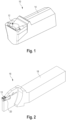
- FIG. 1 A first exemplary embodiment of the cutting insert according to the invention is shown in Fig. 1 shown in a perspective view.
- the cutting plate is designated in its entirety by reference number 10.
- the cutting plate 10 has a cutting area 12 which comes into at least partial contact with the workpiece during machining of a workpiece.
- the shape of this cutting area 12 is therefore essential for chip formation, i.e. the formation of the chips lifted off the workpiece.
- the cutting plate 10 has a clamping section 14.
- This clamping section 14 serves to clamp the cutting plate 10 in a tool holder.
- the clamping section 14 is designed in the shape of a web or bar and preferably has a polygonal or prismatic cross section.
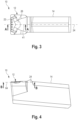
- Fig. 2 shows an exemplary tool 16 in which the cutting plate 10 according to the invention can be used.
- This in Fig. 2 Tool 16 shown is designed as a turning tool.
- This turning tool 16 is particularly suitable for plunge turning or plunge turning.
- the in Fig. 2 Tool shown is just any example of a variety of tools in which the cutting plate 10 according to the invention can be used.
- Tool 16 shown has a tool holder 18, which is essentially bar-shaped in its rear area and has a cutting plate holder 20 in the area of its front end, which serves to hold the cutting plate 10.
- the cutting plate holder 20 is in the in Fig. 2 shown Embodiment designed to be self-clamping, so that no further fastening means are necessary to fix the cutting plate 10 in the cutting plate holder 20.
- additional fastening means such as a clamping screw, are used to clamp the cutting insert 10 in the cutting insert holder 20. It goes without saying that this is also fundamentally possible with the tool 16 according to the invention without departing from the scope of the present invention.
- Fig. 3-10 show further views of the cutting plate 10 according to the invention according to in Fig. 1 shown first embodiment.
- the cutting plate holder 10 has a main cutting edge 22 at its front, front end, which is designed in a straight line.
- the main cutting edge 22 runs orthogonally to a longitudinal direction of the cutting area 12. This longitudinal direction is in 3 and 4 shown as a dashed line, which is marked with the reference number 24.
- the cutting plate 10 has a chip trough 26 in the cutting area 12.
- This chip trough 26 is designed as a depression or as a material recess. It preferably extends over a large part of the width of the cutting area 12.
- a chamfer 28 is also provided in the cutting area 12, which is also referred to in technical language as a negative chamfer due to its orientation.
- the chamfer 28 is divided into three sections 30a-30c. All three portions 30a-30c of the chamfer 28 are arranged in a common planar plane. This level is referred to here as the “chamfer level”.
- the chamfer plane is in Fig. 7 shown with a dashed line which is provided with the reference number 32.
- the chamfer plane 32 is aligned at an acute angle relative to the longitudinal direction 24 of the cutting area 12. Since this angle forms a negative rake angle, the chamfer 28, as already mentioned, is basically also referred to as a negative chamfer.
- the chamfer plane 32 protrudes upwards beyond the chip trough 26.
- the chip trough 26 is therefore arranged below the bevel plane 32 and is not cut by it.
- the chamfer 28 at least partially surrounds the chip trough 26.
- the chamfer 28 preferably runs along the entire length of the main cutting edge 22.
- a first portion 31a of the chamfer 28 adjoins a first end 34a of the main cutting edge 22.
- the third portion 30c of the chamfer 28 adjoins the opposite end 34b of the main cutting edge 22.
- Both partial areas 30a, 30c are designed as flat surfaces which form the two front corner areas of the cutting area 12.
- the two partial areas 30a, 30c are limited by the main cutting edge 22. Laterally, the two partial areas 30a, 30c are delimited on the one hand on their respective inside by the chip trough 26 and on their respective outside by a secondary cutting edge 36a or 36b.
- the two mentioned secondary cutting edges 36a, 36b form the lateral outer ends of the cutting area 12.
- the secondary cutting edges 36a, 36b are each connected to the ends 34a and 34b of the main cutting edge 22 via a radius 38a, 38b.
- chamfers can also be provided as transitions between the secondary cutting edges 36a, 36b and the main cutting edge.
- the second portion 30b of the chamfer 28 extends between the first portion 30a and the third portion 30c.
- This second portion 30b of the chamfer 28 extends at least along a large part of the main cutting edge 22 and runs parallel to it.
- the second portion 30b of the chamfer 28 preferably borders directly on the main cutting edge 22.
- This second partial area 30b is also designed as a flat surface, which is arranged in one and the same chamfer plane 32 with the two flat surfaces that form the partial areas 30a, 30c.
- the chip trough 26 is limited at its front end facing the cutting edge 22 by the second portion 30b of the chamfer 28. At its opposite, rear end, the chip trough 26 is limited by a wall 40.
- This wall 40 forms the rear region of the chip trough 26, viewed in the longitudinal direction 24.
- the wall 40 preferably extends over a large part (more than 50%) of the width of the cutting region 12.
- the chip trough 26 is designed to be mirror-symmetrical to a plane of symmetry 41.
- This plane of symmetry 41 is in Fig. 3 shown as a dashed line and corresponds to that also in Fig. 3 indicated section plane AA.
- the plane of symmetry 41 runs orthogonally to the main cutting edge 22 and is the same distance from the two ends 34a, 34b of the main cutting edge 22. The plane of symmetry 41 therefore runs through a center of the main cutting edge 22.
- the wall 40 is also designed to be mirror-symmetrical to the plane of symmetry 41.
- the wall 40 has five wall regions 42, 44, 46, 48, 50, which adjoin one another in ascending order.
- the first wall area 42 is designed to be mirror-symmetrical to the fifth wall area 50. These two wall regions 42, 50 each form the outer end regions of the wall 40.
- the second wall region 44 is arranged adjacent to the first wall region 42.
- the fourth wall region 48 is arranged adjacent to the fifth wall region 50 and is designed to be mirror-symmetrical to the second wall region 42.
- the third wall region 46 is arranged, which forms the central region of the wall 40 in the width direction of the cutting plate 10, i.e. viewed transversely to the longitudinal direction 24.
- this third wall region 46 is the largest in terms of area of the five wall regions 42-50.
- the third wall area 46 is divided into two equal, mirror-image halves by the plane of symmetry 41.
- a profile line 62 is used below to explain the individual wall areas 42-50 of the wall 40 in more detail Fig. 6 is shown.
- This profile line 62 results from a cut along the in Fig. 4 marked cutting plane BB.
- This cutting plane BB corresponds to an imaginary plane 64, which is aligned orthogonally to the plane of symmetry 41 and runs parallel to the longitudinal direction 24 of the cutting area 12.
- the profile line 62 also has five sections 52, 54, 56, 58, 60.
- the first section 52 of the profile line 62 results from the intersection of the imaginary plane 64 with the first wall region 42.
- the second section 54 of the profile line 62 results from the intersection of the imaginary plane 64 with the second wall region 44.
- the third section 56 of the profile line 62 results from the intersection of the imaginary plane 64 with the third wall region 46.
- the fourth section 58 of the profile line 62 results from the intersection of the imaginary plane 64 with the fourth wall region 48.
- the fifth section 60 of the profile line 62 results from the section the imaginary plane 64 with the fifth wall area 50.
- the first section 52 is designed as a mirror image of the fifth section 60.
- the second section 54 is designed as a mirror image of the fourth section 58.
- the third section 56 is divided into two equal, mirror-image halves by the plane of symmetry 41 and forms the central region of the profile line 62, which connects the second section 54 with the fourth section 58.
- the first, third and fifth sections 52, 56, 60 are each designed to be concave.
- the second and fourth sections 54, 58 are each designed to be rectilinear or convex.
- the second and fourth sections 54, 58 are each designed to be rectilinear.
- the in Fig. 12 In the view shown of the cutting plate 10 according to the second exemplary embodiment, the second section 54 and the fourth section 58, however, are each designed to be convex. Otherwise it differs Fig. 11 and 12
- the exemplary embodiment shown does not differ from that in Fig. 3-7 illustrated first embodiment.
- the first wall region 42 and the fifth wall region 50 of the wall 40 have the shortest distance from the main cutting edge 22 compared to the remaining wall regions 44, 46, 48. At least at least one point on the first section of the profile line 62 has a smaller distance from the main cutting edge 22 as all points on the second, third and fourth sections 54, 56, 58 of the Profile line 62. Preferably, all of the points on the first section 52 of the profile line 62 are at a smaller distance from the main cutting edge 22 than all of the points on the second, the third and the fourth sections 54, 56, 58 of the profile line 62.
- the third wall region 46 has the greatest distance from the main cutting edge 22. Accordingly, all points on the second and fourth sections 54, 58 of the profile line 62 have a smaller distance from the main cutting edge 22 than all points on the third section 56 of the profile line 62.
- the individual sections 52-60 of the profile line 62 are preferably each designed to be kink-free. So they each form a curve that is continuous and differentiable.
- the five wall regions 42-50 of the wall 40 do not merge tangentially into one another. Between the individual sections 52-60 of the profile line 62 there are kinks at the respective transition points. According to the in Fig. 11 and 12 However, in the second exemplary embodiment of the cutting plate 10 according to the invention shown, such kinks only arise between the first wall area 42 and the second wall area 44 and between the fourth wall area 48 and the fifth wall area 50. According to the second exemplary embodiment, however, the second wall area 44 goes tangentially into the third wall area 46 over. Likewise, the third wall region 46 according to the second exemplary embodiment also merges tangentially into the fourth wall region 48.
- both exemplary embodiments of the cutting insert according to the invention described here have in common that the first and fifth sections 52, 60 of the profile line 62 are preferably more curved than the centrally arranged third section 56 of the profile line 62.
- the centrally arranged third section 56 of the profile line 62 forms the comparatively longest of all five sections 52-60.
- the cutting insert 10 according to the invention is particularly suitable due to the described shape of the chip trough 26 and due to the presence of the negative chamfer 28 both for grooving full cuts and for grooving partial cuts as well as for so-called web grooving.
- Fig. 11 several auxiliary lines 66a-66d shown.
- the auxiliary lines 66b and 66c indicate the working area of the cutting plate 10 during a partial cut.
- the auxiliary line 66b indicates a partial cut which extends from the second end 34b of the main cutting edge 22 or from the radius 38b to any point on the main cutting edge 22 which lies between the two ends 34a, 34b of the main cutting edge 22.
- the auxiliary line 66c indicates a partial cut which extends from the first end 34a or the radius 38a to any point on the main cutting edge 22, which is arranged between the two ends 34a, 34b of the main cutting edge 22.
- 60-80% of the total length of the main cutting edge 22 is used for such partial cuts.
- the auxiliary line 66d indicates an exemplary working area during web piercing.
- the cutting plate 10 processes a web provided on the workpiece to be machined during web grooving. This processing is preferably carried out with a central area of the main cutting edge 22, which is symmetrical to the plane of symmetry 41. Depending on the width of the web to be machined, usually 10-60% of the total length of the main cutting edge 22 comes into engagement with the workpiece.
- the second, third and fourth wall areas 44, 46, 48 are not, or at least only minimally, loaded during a full cut.
- the second, third and fourth wall regions 44, 46, 48 of the rear wall of the chip trough 26 therefore do not influence the processing during a full cut at all or at least only very slightly.
- auxiliary line 66b essentially the third partial area 30c of the negative chamfer 28 and the second wall area 44 act as functional surfaces that significantly influence chip formation.
- a large part of the chip removed from the workpiece accumulates on these two opposing surfaces 30c, 44.
- a lateral chip taper can be achieved due to the shape of these two surfaces 30c, 44, so that short spiral chips can be produced even when machining a partial cut.
- partial cut processing as indicated by the auxiliary line 66c.
- the first partial area 30a of the negative chamfer 28 and the fourth wall area 48 act as opposing functional surfaces that significantly influence chip formation.
- the middle part of the wall 40 i.e. the concavely curved third wall region 46
- the middle part of the wall 40 is particularly responsible for the chip formation or chip shaping.
- the second partial region 30b of the negative chamfer 28 stabilizes the central region of the main cutting edge 22 which is in engagement with the workpiece to be machined.
- the concave curvature of the third wall region 46 of the wall 40 in turn ensures a lateral chip taper, which prevents a comparatively early chip breakage enables and thus guarantees the formation of comparatively short chips even when bar grooving.
- elevations 68 can be provided in the cutting area 12 of the cutting plate 10 according to the invention.
- a total of five of these elevations 68 are arranged in the chip trough 26.
- the elevations 68 are arranged parallel to one another in a row along the main cutting edge 22. They protrude from a bottom surface 70 arranged in the chip trough 26, which is preferably designed as a planar surface and adjoins the second portion 30b of the negative chamfer 28.
- each of the elevations 68 has a surface section that lies in the chamfer plane 32.
- the elevations 68 preferably merge tangentially into the second portion 30b of the negative chamfer 28. This contributes to further stabilization of the main cutting edge 22.
- the width d 2 of the chip trough 26 is preferably 75-95% of the total width d 1 of the cutting plate 10 in the cutting area 12.
- the width d 3 of the second portion 30b of the negative chamfer 28, which corresponds to the width of the bottom surface 70, is preferably 60-90 % of the total width d 1 of the cutting plate 10 in the cutting area 12.
- the width d 4 of the elevations 68 is preferably 5-12% of the width d 3 . The following therefore preferably applies: d 1 > d 2 ⁇ d 3 > d 4 .
- the angle ⁇ that the main cutting edge 22 includes with a boundary line 72 which extends between the chip trough 26 and the first portion 30a of the chamfer 28 is preferably 30°-90°. It is understood that the opposite boundary line 74, which extends between the third portion 30c of the chamfer 28 and the chip trough, includes the corresponding counter angle with the main cutting edge 22.
- a tangent 76 is also shown, which touches the second section 54 of the profile line 62 in the transition point between the second section 54 and the first section 52.
- the tangent 78 shown touches the fourth section 58 of the profile line 62 at the transition point between the fifth section 60 and the fourth section 58.
- the tangents 76, 78 intersect at a point 80.
- the tangents 82 and 84 are drawn.
- the tangent 82 touches the third section 56 of the profile line 62 in the transition point between the second section 54 and the third section 56.
- the tangent 84 touches the third section 56 of the profile line 62 in the transition point between the third section 56 and the fourth section 58.
- the tangents 82, 84 intersect at point 86. This point 86 is at a greater distance from the main cutting edge 22 than point 80.
- the longitudinal section shown shows that the chip trough 26 is preferably concavely curved in each section parallel to the plane of symmetry 41.
- the second wall region 44 and the fourth wall region 48 are more curved than the third wall region 46. This is determined, among other things, by the in Fig. 10 illustrated angles ⁇ 1 and ⁇ 2 .
- the first wall region 42 and the fifth wall region 50 are each more curved than the second wall region 44 and the fourth wall region 48 (see angle ⁇ 3 ).
- ⁇ 3 > ⁇ 2 > ⁇ 1 applies.
- the main cutting edge 22 is formed at the transition between the chamfer 28 arranged in the chamfer plane 32 and a free surface 88.
- This open space 88 forms the front face of the cutting plate 10.
- the chamfer 28 is inclined at an angle ⁇ relative to the open surface 88, where ⁇ ⁇ 90 °. ⁇ > 90° is particularly preferred.
Landscapes
- Engineering & Computer Science (AREA)
- Mechanical Engineering (AREA)
- Milling Processes (AREA)
- Cutting Tools, Boring Holders, And Turrets (AREA)
Applications Claiming Priority (2)
| Application Number | Priority Date | Filing Date | Title |
|---|---|---|---|
| DE102019121468.8A DE102019121468A1 (de) | 2019-08-08 | 2019-08-08 | Schneidplatte und Werkzeug mit einer solchen Schneidplatte |
| PCT/EP2020/072175 WO2021023835A1 (de) | 2019-08-08 | 2020-08-06 | Schneidplatte und werkzeug mit einer solchen schneidplatte |
Publications (3)
| Publication Number | Publication Date |
|---|---|
| EP4010137A1 EP4010137A1 (de) | 2022-06-15 |
| EP4010137B1 true EP4010137B1 (de) | 2024-03-20 |
| EP4010137C0 EP4010137C0 (de) | 2024-03-20 |
Family
ID=71996005
Family Applications (1)
| Application Number | Title | Priority Date | Filing Date |
|---|---|---|---|
| EP20753736.6A Active EP4010137B1 (de) | 2019-08-08 | 2020-08-06 | Schneidplatte und werkzeug mit einer solchen schneidplatte |
Country Status (8)
| Country | Link |
|---|---|
| US (1) | US20220143713A1 (zh) |
| EP (1) | EP4010137B1 (zh) |
| JP (1) | JP2022543080A (zh) |
| CN (1) | CN114206529A (zh) |
| CA (1) | CA3150044A1 (zh) |
| DE (1) | DE102019121468A1 (zh) |
| MX (1) | MX2022001409A (zh) |
| WO (1) | WO2021023835A1 (zh) |
Families Citing this family (1)
| Publication number | Priority date | Publication date | Assignee | Title |
|---|---|---|---|---|
| JP7155407B2 (ja) * | 2019-03-29 | 2022-10-18 | 京セラ株式会社 | 切削インサート、切削工具及び切削加工物の製造方法 |
Family Cites Families (17)
| Publication number | Priority date | Publication date | Assignee | Title |
|---|---|---|---|---|
| SE452273B (sv) * | 1986-05-07 | 1987-11-23 | Seco Tools Ab | Sker for avstickning |
| SE508121C2 (sv) * | 1992-04-30 | 1998-08-31 | Sandvik Ab | Skär för svarvnings- och spårstickningsverktyg |
| DE4310131A1 (de) * | 1993-03-29 | 1994-10-06 | Krupp Widia Gmbh | Schneideinsatz |
| SE502084C2 (sv) * | 1993-04-05 | 1995-08-07 | Sandvik Ab | Skärplatta med konkavt krökta spånbrytare |
| GB2290994B (en) * | 1994-07-05 | 1998-06-10 | Valenite Inc | Cutting insert |
| DE4433389A1 (de) * | 1994-09-12 | 1996-03-14 | Widia Gmbh | Stecheinsatz zur spanabhebenden Bearbeitung von Werkstücken |
| JPH08132302A (ja) * | 1994-11-08 | 1996-05-28 | Mitsubishi Materials Corp | スローアウェイチップ |
| SE508665C2 (sv) * | 1997-12-22 | 1998-10-26 | Sandvik Ab | Skär för spårstickning |
| DE10006303A1 (de) * | 2000-02-12 | 2001-08-23 | Kemmer Hartmetallwerkzeuge Gmb | Schneideinsatz, insbesondere Abstechschneideinsatz |
| DE10042692A1 (de) * | 2000-08-31 | 2002-03-28 | Horn P Hartmetall Werkzeugfab | Vorrichtung zum spanenden Bearbeiten von Werkstücken, insbesondere Metallschneideeinsatz mit einer zwischen Stegen angeordneten Spanformfläche |
| DE10344961A1 (de) * | 2003-09-27 | 2005-04-28 | Kennametal Inc | Schneidkörper, insbesondere zum Stech- und Längsdrehen |
| CN2871070Y (zh) * | 2006-03-31 | 2007-02-21 | 株洲钻石切削刀具股份有限公司 | 一种径向切槽和轴向车削用刀片 |
| CN101306476B (zh) * | 2008-06-30 | 2010-04-14 | 株洲钻石切削刀具股份有限公司 | 用于加工高粘性、耐高温金属材料的切削刀片 |
| WO2015064559A1 (ja) * | 2013-10-29 | 2015-05-07 | 京セラ株式会社 | 切削インサート及び切削工具、並びにそれらを用いた切削加工物の製造方法 |
| CN106457412B (zh) * | 2014-05-22 | 2018-08-07 | 京瓷株式会社 | 切削镶刀、切削工具以及切削加工物的制造方法 |
| US10384268B1 (en) * | 2018-02-05 | 2019-08-20 | Iscar, Ltd. | Grooving insert having rearwardly pointing arrowhead-shaped chip former |
| CN209681183U (zh) * | 2018-11-19 | 2019-11-26 | 炎陵欧科亿数控精密刀具有限公司 | 一种可转位双面槽切削刀片 |
-
2019
- 2019-08-08 DE DE102019121468.8A patent/DE102019121468A1/de active Pending
-
2020
- 2020-08-06 EP EP20753736.6A patent/EP4010137B1/de active Active
- 2020-08-06 WO PCT/EP2020/072175 patent/WO2021023835A1/de active Application Filing
- 2020-08-06 CN CN202080055512.1A patent/CN114206529A/zh active Pending
- 2020-08-06 MX MX2022001409A patent/MX2022001409A/es unknown
- 2020-08-06 CA CA3150044A patent/CA3150044A1/en active Pending
- 2020-08-06 JP JP2022506550A patent/JP2022543080A/ja active Pending
-
2022
- 2022-01-26 US US17/585,084 patent/US20220143713A1/en active Pending
Also Published As
| Publication number | Publication date |
|---|---|
| US20220143713A1 (en) | 2022-05-12 |
| MX2022001409A (es) | 2022-03-25 |
| EP4010137A1 (de) | 2022-06-15 |
| CN114206529A (zh) | 2022-03-18 |
| WO2021023835A1 (de) | 2021-02-11 |
| DE102019121468A1 (de) | 2021-02-11 |
| JP2022543080A (ja) | 2022-10-07 |
| CA3150044A1 (en) | 2021-02-11 |
| EP4010137C0 (de) | 2024-03-20 |
Similar Documents
| Publication | Publication Date | Title |
|---|---|---|
| EP1675699B1 (de) | Schneidkörper, insbesondere zum stech- und längsdrehen | |
| DE69507245T2 (de) | Ein ersetzbarer Schneideinsatz | |
| DE19901456B4 (de) | Wendeschneidplatte | |
| DE69409364T2 (de) | Schneideinsatz mit spiralförmiger erhabener fläche und angrenzender ausnehmung | |
| DE69312603T2 (de) | Schneideinsatz für einen Fräser | |
| DE4315251B4 (de) | Schneideinsatz | |
| DE3323442C2 (zh) | ||
| EP0454824B1 (de) | Stechdrehwerkzeug | |
| EP2183071B1 (de) | Bohrer | |
| DE69900567T2 (de) | Stechschneideinsatz | |
| DE69915315T2 (de) | Schneideinsatz zum einstechen | |
| EP3038776B1 (de) | Bohrer | |
| DE4400570C2 (de) | Schneideinsatz | |
| EP0361031B1 (de) | Messerplatte für die Präzisionsbearbeitung insbesondere von Bohrungen | |
| EP2848343B1 (de) | Fräser mit Kordel aus einem speziellen Zahnprofil | |
| DE3029628A1 (de) | Auswechselbarer schneideinsatz | |
| WO1996008331A1 (de) | Schneideinsatz | |
| EP3694665B1 (de) | Schneidplatte und werkzeug zur spanenden bearbeitung eines werkstücks | |
| EP0673700B1 (de) | Reibahle | |
| DE60019438T2 (de) | Schneideinsatz zum einstecken | |
| EP4010137B1 (de) | Schneidplatte und werkzeug mit einer solchen schneidplatte | |
| EP1283083A1 (de) | Frässchneideinsatz und Fräswerkzeug | |
| DE2734095C2 (de) | Schneidwerkzeug zum Schälen auf einer Drehbank | |
| EP0691897A1 (de) | Schneideinsatz | |
| EP1213080A1 (de) | Werkzeug zur spanabtragenden Bearbeitung von Bohrungsoberflächen |
Legal Events
| Date | Code | Title | Description |
|---|---|---|---|
| STAA | Information on the status of an ep patent application or granted ep patent |
Free format text: STATUS: UNKNOWN |
|
| STAA | Information on the status of an ep patent application or granted ep patent |
Free format text: STATUS: THE INTERNATIONAL PUBLICATION HAS BEEN MADE |
|
| PUAI | Public reference made under article 153(3) epc to a published international application that has entered the european phase |
Free format text: ORIGINAL CODE: 0009012 |
|
| STAA | Information on the status of an ep patent application or granted ep patent |
Free format text: STATUS: REQUEST FOR EXAMINATION WAS MADE |
|
| 17P | Request for examination filed |
Effective date: 20220223 |
|
| AK | Designated contracting states |
Kind code of ref document: A1 Designated state(s): AL AT BE BG CH CY CZ DE DK EE ES FI FR GB GR HR HU IE IS IT LI LT LU LV MC MK MT NL NO PL PT RO RS SE SI SK SM TR |
|
| DAV | Request for validation of the european patent (deleted) | ||
| DAX | Request for extension of the european patent (deleted) | ||
| GRAP | Despatch of communication of intention to grant a patent |
Free format text: ORIGINAL CODE: EPIDOSNIGR1 |
|
| STAA | Information on the status of an ep patent application or granted ep patent |
Free format text: STATUS: GRANT OF PATENT IS INTENDED |
|
| INTG | Intention to grant announced |
Effective date: 20230927 |
|
| GRAS | Grant fee paid |
Free format text: ORIGINAL CODE: EPIDOSNIGR3 |
|
| GRAA | (expected) grant |
Free format text: ORIGINAL CODE: 0009210 |
|
| STAA | Information on the status of an ep patent application or granted ep patent |
Free format text: STATUS: THE PATENT HAS BEEN GRANTED |
|
| AK | Designated contracting states |
Kind code of ref document: B1 Designated state(s): AL AT BE BG CH CY CZ DE DK EE ES FI FR GB GR HR HU IE IS IT LI LT LU LV MC MK MT NL NO PL PT RO RS SE SI SK SM TR |
|
| REG | Reference to a national code |
Ref country code: GB Ref legal event code: FG4D Free format text: NOT ENGLISH |
|
| REG | Reference to a national code |
Ref country code: CH Ref legal event code: EP |
|
| REG | Reference to a national code |
Ref country code: DE Ref legal event code: R096 Ref document number: 502020007424 Country of ref document: DE |
|
| REG | Reference to a national code |
Ref country code: IE Ref legal event code: FG4D Free format text: LANGUAGE OF EP DOCUMENT: GERMAN |
|
| U01 | Request for unitary effect filed |
Effective date: 20240419 |
|
| U07 | Unitary effect registered |
Designated state(s): AT BE BG DE DK EE FI FR IT LT LU LV MT NL PT SE SI Effective date: 20240425 |
|
| PG25 | Lapsed in a contracting state [announced via postgrant information from national office to epo] |
Ref country code: GR Free format text: LAPSE BECAUSE OF FAILURE TO SUBMIT A TRANSLATION OF THE DESCRIPTION OR TO PAY THE FEE WITHIN THE PRESCRIBED TIME-LIMIT Effective date: 20240621 |
|
| PG25 | Lapsed in a contracting state [announced via postgrant information from national office to epo] |
Ref country code: HR Free format text: LAPSE BECAUSE OF FAILURE TO SUBMIT A TRANSLATION OF THE DESCRIPTION OR TO PAY THE FEE WITHIN THE PRESCRIBED TIME-LIMIT Effective date: 20240320 Ref country code: RS Free format text: LAPSE BECAUSE OF FAILURE TO SUBMIT A TRANSLATION OF THE DESCRIPTION OR TO PAY THE FEE WITHIN THE PRESCRIBED TIME-LIMIT Effective date: 20240620 |
|
| PG25 | Lapsed in a contracting state [announced via postgrant information from national office to epo] |
Ref country code: RS Free format text: LAPSE BECAUSE OF FAILURE TO SUBMIT A TRANSLATION OF THE DESCRIPTION OR TO PAY THE FEE WITHIN THE PRESCRIBED TIME-LIMIT Effective date: 20240620 Ref country code: NO Free format text: LAPSE BECAUSE OF FAILURE TO SUBMIT A TRANSLATION OF THE DESCRIPTION OR TO PAY THE FEE WITHIN THE PRESCRIBED TIME-LIMIT Effective date: 20240620 Ref country code: HR Free format text: LAPSE BECAUSE OF FAILURE TO SUBMIT A TRANSLATION OF THE DESCRIPTION OR TO PAY THE FEE WITHIN THE PRESCRIBED TIME-LIMIT Effective date: 20240320 Ref country code: GR Free format text: LAPSE BECAUSE OF FAILURE TO SUBMIT A TRANSLATION OF THE DESCRIPTION OR TO PAY THE FEE WITHIN THE PRESCRIBED TIME-LIMIT Effective date: 20240621 |