EP4010073B1 - Verfahren zur verwendung mit einer strahlentherapievorrichtung - Google Patents
Verfahren zur verwendung mit einer strahlentherapievorrichtung Download PDFInfo
- Publication number
- EP4010073B1 EP4010073B1 EP20754205.1A EP20754205A EP4010073B1 EP 4010073 B1 EP4010073 B1 EP 4010073B1 EP 20754205 A EP20754205 A EP 20754205A EP 4010073 B1 EP4010073 B1 EP 4010073B1
- Authority
- EP
- European Patent Office
- Prior art keywords
- voltage
- bending magnet
- radiotherapy device
- fault
- magnet assembly
- Prior art date
- Legal status (The legal status is an assumption and is not a legal conclusion. Google has not performed a legal analysis and makes no representation as to the accuracy of the status listed.)
- Active
Links
Images



Classifications
-
- A—HUMAN NECESSITIES
- A61—MEDICAL OR VETERINARY SCIENCE; HYGIENE
- A61N—ELECTROTHERAPY; MAGNETOTHERAPY; RADIATION THERAPY; ULTRASOUND THERAPY
- A61N5/00—Radiation therapy
- A61N5/10—X-ray therapy; Gamma-ray therapy; Particle-irradiation therapy
- A61N5/1048—Monitoring, verifying, controlling systems and methods
-
- H—ELECTRICITY
- H05—ELECTRIC TECHNIQUES NOT OTHERWISE PROVIDED FOR
- H05H—PLASMA TECHNIQUE; PRODUCTION OF ACCELERATED ELECTRICALLY-CHARGED PARTICLES OR OF NEUTRONS; PRODUCTION OR ACCELERATION OF NEUTRAL MOLECULAR OR ATOMIC BEAMS
- H05H7/00—Details of devices of the types covered by groups H05H9/00, H05H11/00, H05H13/00
- H05H7/04—Magnet systems, e.g. undulators, wigglers; Energisation thereof
-
- A—HUMAN NECESSITIES
- A61—MEDICAL OR VETERINARY SCIENCE; HYGIENE
- A61N—ELECTROTHERAPY; MAGNETOTHERAPY; RADIATION THERAPY; ULTRASOUND THERAPY
- A61N5/00—Radiation therapy
- A61N5/10—X-ray therapy; Gamma-ray therapy; Particle-irradiation therapy
- A61N2005/1085—X-ray therapy; Gamma-ray therapy; Particle-irradiation therapy characterised by the type of particles applied to the patient
- A61N2005/1089—Electrons
-
- A—HUMAN NECESSITIES
- A61—MEDICAL OR VETERINARY SCIENCE; HYGIENE
- A61N—ELECTROTHERAPY; MAGNETOTHERAPY; RADIATION THERAPY; ULTRASOUND THERAPY
- A61N5/00—Radiation therapy
- A61N5/10—X-ray therapy; Gamma-ray therapy; Particle-irradiation therapy
- A61N5/1077—Beam delivery systems
- A61N5/1081—Rotating beam systems with a specific mechanical construction, e.g. gantries
-
- H—ELECTRICITY
- H05—ELECTRIC TECHNIQUES NOT OTHERWISE PROVIDED FOR
- H05H—PLASMA TECHNIQUE; PRODUCTION OF ACCELERATED ELECTRICALLY-CHARGED PARTICLES OR OF NEUTRONS; PRODUCTION OR ACCELERATION OF NEUTRAL MOLECULAR OR ATOMIC BEAMS
- H05H7/00—Details of devices of the types covered by groups H05H9/00, H05H11/00, H05H13/00
- H05H7/04—Magnet systems, e.g. undulators, wigglers; Energisation thereof
- H05H2007/045—Magnet systems, e.g. undulators, wigglers; Energisation thereof for beam bending
Definitions
- This disclosure relates to the field of remote diagnostics, and in particular to a method of identifying the nature of a fault in a radiotherapy device performing sub-optimally.
- Radiotherapy devices are an important tool in modern cancer treatment. Radiotherapy devices are large, complex machines, with many moving parts and inter-operating mechanisms. Despite precision engineering and rigorous testing, some component parts of a radiotherapy machines may start to degrade over the lifetime of the machine. This can sometimes lead to sub-optimal operation and even the occasional safety override.
- a safety override or "interrupt” occurs, whereby the machine stops delivering radiation to ensure patient safety.
- Such an event is inconvenient, as it adds time to the treatment, and in some cases means the treatment session must finish prematurely. Unplanned equipment downtime can disrupt planned treatment schedules, and may be expensive for the owner, be it due to loss of revenue, servicing and repair costs, or both.
- the present invention seeks to address these and other disadvantages encountered in the prior art by providing a method of identifying, preferably remotely, the nature of a fault in a radiotherapy device, for example a device which is performing sub-optimally.
- EP 1454657A2 describes a particle beam therapy system which transports an ion beam emitted from an accelerator to one of a plurality of treatment rooms.
- WO9012413 describes a raster scan control system for use with a charged-particle beam delivery system which provides control of large currents driving an inductive load.
- the present disclosure relates to a method of determining the nature of a fault in a radiotherapy machine or device.
- the device may be suitable for delivering a beam of radiation to a patient in order to treat a tumour.
- An example of a radiation source for producing a beam is a linear accelerator (LINAC).
- Clinical LINAC devices are configured to deliver high energy radiation to a patient.
- Radiotherapy machines are beginning to be configured to produce and record a large amount of data as they operate; for example radiotherapy machines are configured to provide sensor readings from a variety of different sensors. These sensors produce data which can be stored in a database. Radiotherapy devices may also be configured to allow remote connection, enabling service engineers to access a wealth of information about any connected machine without having to travel to the site where the machine is located. It is expected that, in many cases, machines may be returned to optimal performance without an engineer ever having to physically interact with the machine. However, there will still be occasions where the fault cannot be fixed remotely, and an engineer must be sent to: inspect the machine; determine the nature of the fault; and perform any maintenance required. If the repair involves replacing a part, further machine downtime is required before the machine can be brought back online.
- One potential fault in a LINAC device relates to a malfunctioning of the bending magnet assembly of the LINAC. This may, for example be caused by reduced performance of the cooling apparatus for the bending magnet assembly.
- the cooling apparatus may experience a blockage, which may manifest itself gradually over time, or indeed suddenly, if some foreign body enters the cooling circuitry and blocks a cooling line, or a build up of such bodies occurs over time and results in reduced flow of cooling fluid.
- the bending magnet assembly may be subject to physical motion, as it forms part of a moveable gantry. This in turn can negatively impact beam quality.
- Machines with bending magnet assembly related faults often have machine output fluctuations, and so a field service engineer investigating the fault may incorrectly conclude that the sub-optimal performance of the machine is due to, for example, a magnetron issue, rather than due to a fault with the cooling system of the bending magnet assembly.
- the present disclosure advantageously allows a determination that the nature of the fault is associated with the bending magnet assembly.
- the source 102 of radiofrequency waves produces radiofrequency waves.
- the source 102 of radiofrequency waves is coupled to the waveguide 104, and is configured to pulse radiofrequency waves into the waveguide 104.
- Radiofrequency waves pass from the source 102 of radiofrequency waves through an RF input window and into a RF input connecting pipe or tube.
- the RF input connecting pipe or tube is coupled with the waveguide, and may join the waveguide at a substantially 90° angle as shown in figure 1 .
- the connecting tube or pipe may join the waveguide via a so-called 'elbow joint' or 't-shaped joint'.
- a source 106 of electrons such as an electron gun, is coupled to the waveguide 104 and is configured to inject electrons into the waveguide 104.
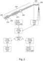
- FIG. 2 depicts a cross-section through a vacuum tube of a linac.
- the vacuum tube is comprised of an electron gun 202, a waveguide 204, and a flight tube 206.
- the flight tube is arranged to pass through a bending magnet assembly 208.
- the electron gun 202 is configured to inject electrons into the waveguide 204.
- the electron beam may be focused by a first arrangement of focusing magnets 210 and a second arrangement of focusing magnets 215.
- the beam is 'steered', i.e. directed, by a first arrangement of steering magnets 220 and a second arrangement of steering magnets 225.
- the electron gun 202, waveguide 204 and flight tube 206 are kept under high vacuum conditions by a vacuum system or suitable vacuum apparatus.
- the electron beam is focused and directed by the bending magnet assembly 208.
- the bending magnet assembly 208 comprises a plurality of electromagnets arranged around the flight tube so as to bend the electron beam.
- the example shown in figure 3 comprises 3 electromagnet coils which combine to form an achromatic triple-magnet array.
- the evacuated flight tube contains the electron beam and is positioned between pole pieces of the bending magnet assembly.
- the first magnet (M1) which may eb described as a bending coarse magnet, acts as an energy analyser and its magnetic field bends the electron beam through a first angle
- the pole pieces of the first magnet may be specially shaped so that energy dispersion takes place along the beam path, resulting in an energy separation spectrum at the output of the first magnet.
- the field strength of this magnet is adjusted so that electrons of the required mean energy are transmitted.
- the second magnet (M2) which may be described as a bending fine magnet, reverses the angle of bending action, that is to say it bends the electron beam through an equal and opposite (first) angle, from the first magnet and the field from its specially shaped pole pieces produces a focusing action in two orthogonal directions. In this region of the beam path, the widest energy separation occurs before beam convergence commences.
- the converging beam from the second magnet is directed into the third magnet (M3), which also has specially shaped pole pieces.
- This magnet bends the beam through a second angle of over 90 degrees and completes the two-dimensional focusing action.
- the beam may be focused finally to an area of approximately 2 mm in diameter at the target.
- the first angle is 44 degrees
- the second angle is 112 degrees, although it will be appreciated that other angles may be used.
- the coils of all three magnets are water cooled. There are 2 coils per magnet. There is a thermal switch attached to each of the six coils and all six switches are wired in series to provide the bending magnet over-temperature circuit.
- the bending magnet power supply units, PSUs comprise two thyristor-controlled current-stabilized power supplies located in low voltage PSU area 13.
- the main supply (PSU1) contains a three-phase, full-wave, thyristor controlled bridge-rectifier and three LV PSU control PCBs.
- the secondary supply (PSU2) contains a single phase, full wave thyristor controlled bridge rectifier with a single control PCB.
- the linac also comprises a voltage sensor 230, e.g. a voltmeter, at the bending magnet apparatus.
- the voltage sensor 230 may be comprised within the bending magnet power supply.
- the voltage sensor 230 is suitable for detecting, and is configured to detect, the actual voltage across the bending magnet assembly.
- the voltage sensor 230 is communicatively coupled with a device controller 240, and data relating to the bending magnet voltage is communicated to the device controller.
- the bending magnet voltage is measured by the voltage sensor and communicated to the device controller 240 with a particular frequency, for example the voltage sensor 230 may provide a voltage measurement to the device controller 240 every second.
- the voltage sensor comprises means with which to communicate with the device controller 240.
- the voltage sensor may comprise suitable processing circuitry and transmitting antennas.
- the voltage sensor is electronically and/or communicatively coupled to the device controller 240.
- the device controller 240 receives signals from the voltage sensor as they are generated, or produced, by the voltage sensor.
- the device controller 240 is electronically and/or communicatively coupled to a device controller memory 245.
- the device controller 240 and device controller memory 245 may be configured to store signals generated by the voltage sensor.
- the generated signals from the voltage sensor comprise sensor data.
- the device controller 240 is communicatively coupled to a central controller 270, for example via a network 250.
- the device controller 240 is configured to transmit, i.e. send, the sensor data to the central controller 270 to be stored on the central controller memory 275.
- the central memory 275 may comprise a number of different servers as part of a cloud storage solution.
- the central controller may be communicatively coupled to a plurality of radiotherapy devices via network 250, each of which are configured to transmit signals to the central controller 270 to be stored on central memory 275.
- Central controller 270 is adapted and configured to process received signals and store them in a database. Processing the signals may comprise, for example, calculating and storing daily averages of particular sensor data.
- the radiotherapy device has a variety of other sensors (not shown), the signals and readings from which are communicated to the device controller 240.
- the signals may be stored in the device controller memory 245 and/or may be communicated via the network to the central controller 270.
- the data may be uploaded to the central controller 270 as it is generated, or may be stored on the device controller memory 245 in order to be uploaded as a batch upload, for example at regular time intervals.
- the data may be continuously gathered by the device controller 240, for example the sensor signals may be sampled every 4 seconds while the device is not delivering radiation, and data is uploaded if the data shows a particular variance from the previously uploaded data point.
- the data points are uploaded when there is a change of +/-0.04, and the device controller looks for a new data item once every 4 seconds while the device is not delivering radiation, and once every second while the linac is delivering radiation.
- the data is stored in a database on central memory 275, which may comprise data from sensors, for example the data includes the voltage values as denoted by signals from the voltage sensor, the degree of rotation of the gantry, whether or not radiation is being delivered at a particular time and the dose rate and machine output as indicated by a dosimeter or monitor chamber, as well as the water temperature at various points around the water cooling system.
- data includes the voltage values as denoted by signals from the voltage sensor, the degree of rotation of the gantry, whether or not radiation is being delivered at a particular time and the dose rate and machine output as indicated by a dosimeter or monitor chamber, as well as the water temperature at various points around the water cooling system.
- the device controller 240 and central controller 270 are both also communicatively coupled to a remote controller 260.
- the remote controller 260 may access the central database, which stores information and data regarding a plurality of radiotherapy devices, through the database 250 and by using a suitable software platform.
- the remote controller 260 may also access the device controller 240 to obtain real-time information regarding a particular radiotherapy machine.
- the device, central and remote controllers may each be described as a processor, computer, or computing device.
- the controllers may be connected (e.g., networked) to each other and/or to other machines in a Local Area Network (LAN), an intranet, an extranet, or the Internet.
- LAN Local Area Network
- the controllers may each operate in the capacity of a server or a client machine in a client-server network environment, or as a peer machine in a peer-to-peer (or distributed) network environment.
- the controllers may each be a personal computer (PC), a tablet computer, a set-top box (STB), a Personal Digital Assistant (PDA), a cellular telephone, a web appliance, a server, a network router, switch or bridge, or any machine capable of executing a set of instructions (sequential or otherwise) that specify actions to be taken by that machine.
- PC personal computer
- PDA Personal Digital Assistant
- STB set-top box
- a cellular telephone a web appliance
- server e.g., a server
- network router e.g., switch or bridge
- the approaches of the present disclosure may be embodied on one or more of the device controller memory and the remote controller memory, or any other computer-readable medium.
- the medium may be a non-transitory computer-readable medium.
- the computer-readable medium carries computer-readable instructions arranged for execution upon a processor so as to make the controller / processor carry out any or all of the methods described herein.
- the term "computer-readable medium" as used herein refers to any medium that stores data and/or instructions for causing a processor to operate in a specific manner.
- Such storage medium may comprise non-volatile media and/or volatile media.
- Non-volatile media may include, for example, optical or magnetic disks.
- Volatile media may include dynamic memory.
- Exemplary forms of storage medium include, a floppy disk, a flexible disk, a hard disk, a solid state drive, a magnetic tape, or any other magnetic data storage medium, a CD-ROM, any other optical data storage medium, any physical medium with one or more patterns of holes, a RAM, a PROM, an EPROM, a FLASH-EPROM, NVRAM, and any other memory chip or cartridge.
- the bending magnet In a linac device, it is important that the bending magnet function stably so that the beam is focussed correctly on the target, and so that the x-rays be emitted correctly from the target.
- the operating temperature of the bending magnet coils may rise with time through use, and this can be indirectly measured through measuring the bending magnet voltage.
- the temperature should be kept constant by virtue of the operation of the cooling assembly.
- the measured bending magnet voltage provides an indirect indication of the operating temperature of the bending magnet assembly, assuming the bending magnet assembly is receiving a stable input current, and the cooling assembly is functioning correctly.
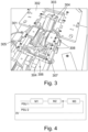
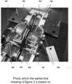
- a representation of a bending magnet is shown in Fig. 3 .
- a bending magnet apparatus is shown and comprises bending coarse stage and a bending fine stage 3 pairs of coils including coils which make up both a bending coarse stage and a bending fine stage.
- the bending magnet apparatus comprises a bending fine flying lead 301, a magnet plate 302, on which a bracket 303 is mounted. Bending magnet coils 304 are mounted in the bending magnet assembly.
- the bending magnet assembly also comprises water manifolds 305, 307, from which extend cooling pipes.
- the cooling fluid flows around the bending magnet coils 304 in order to regulate the temperature of the bending magnet assembly during operation of the linac.
- the bending machine apparatus comprises coil retaining brackets 306 which hold the coils in place.
- the bending coarse stage comprises positive and negative power supply connections 308. Water is used as a cooling fluid, though other cooling fluids may be used.
- the bending magnet assembly comprises a plurality of thermal cut-outs located at the bending coils.
- the thermal cut-outs operate to suspend the accelerator when an operating temperature cut-off threshold is reached.
- the bending magnet assembly is powered by a pair of low voltage power supply units (LVPSU), and these comprise two thyristor-controlled current-stabilized power supplies, located in low voltage PSU.
- LVPSU low voltage power supply units
- a PSU arrangement is shown in figure 4 .
- Figure 4 shows an arrangement for delivering power to the bending magnet assembly. All three magnets M1, M2 and M3are supplied by PSU 1, and PSU2 is a top-up supply for magnet 3 only. It is used to compensate for the fact that, unlike magnet M1 and magnet M2, the current in magnet M3 is not linearly related to its field strength.
- the bending coarse and bending fine set current values are applied to a control circuit board. The outputs from the board are control signals applied to the inputs of PSU 1 and PSU 2.
- the bending magnet coil currents may be monitored by respective PSU control PCBs, which detect the voltage across resistors (not shown) located in the current return path of each PSU. The signals are fed back to the central control system, and may be used to apply servo-control to the bending coarse and bending fine current values.
- the bending magnet voltage is measured at the bending magnet assembly in order to assess the performance of the bending magnet assembly.
- the LV PSUs may comprise smoothing chokes (not shown), at which voltage testing can be conveniently carried out.
- the first sensor or sensors may be configured to provide signals indicative of voltage at measurement locations in the bending magnet assembly.
- the sensors may comprise any number of possible sensors which are suitable to measure voltage, current or resistance.
- Figure 5 shows a graph generated using data from a database of sensor values as provided by sensors such as the sensors 230 depicted in figure 2 .
- the graph shows time along the X axis and voltage along the Y axis.
- the unit of the y axis is a semi-arbitrary unit which is derived from the voltage values in the bending magnet assembly. It can be seen that the mean voltage recorded shows little variation prior to 2018-11-30, but then rises steadily until the most recently recorded data point.
- the graph shows signals received from the bending magnet assembly as generated by the bending magnet voltage sensor.
- the graph demonstrates the type of signals which may be received from the device controller and which may be accessible by a remote controller.
- the line which is generally uppermost on the graph is the bending magnet voltage daily maximum reading. Each data point is the maximum value for a particular day, i.e. the maximum value for a particular date between a period from 00:00 to 23:59.
- the line which is generally lowermost on the graph is the bending magnet voltage daily minimum reading, with each data point being the minimum value that day.
- the line which is generally between the maximum and minimum lines is the daily average line.
- Each data point on this line is the average bending magnet voltage value for a particular day. In an implementation, it is this daily average value for the bending magnet voltage which is compared to a first threshold in order to determine whether a fault with the bending magnet assembly exists.
- a voltage value is received.
- the voltage value is derived from signals from the voltage sensor.
- the actual voltage supplied to the bending magnet assembly may vary slightly in the vicinity of this optimal value as the radiation beam is applied and because the current and/or the voltage supplied to the bending magnet assembly is controlled by a servomechanism. If the current is adjusted by the servomechanism, the voltage at the bending magnet assembly changes as the current is adjusted.
- the major variation in voltage from an optimal or mean value during normal operation is due to changes in coil temperature of the bending magnets.
- the voltage measured by the voltage sensor 230 and received by the device controller 240 varies as the linac operates.
- the voltage value received at step 610 may be an average of signals or values received from the voltage sensor over a time period.
- the voltage value may be measurement of an average voltage received from the bending magnet assembly over the time period.
- the time period is a day, such that the voltage value is a daily average of the voltage supplied to the bending magnet assembly.
- the method may further comprise deriving the voltage value by calculating or otherwise determining the average of the received signals from the voltage sensor 230 over the time period.
- the voltage value is processed.
- the processing of the voltage value is described in more detail in relation to figure 7 , though in a preferred embodiment the processing of the voltage value comprises determining whether the voltage value meets at least one threshold criterion and determining whether the voltage value has changed by a threshold amount or more in a particular time period.
- step 630 based on the processing of the voltage value, it is determined whether repair or replacement of the bending magnet assembly should be scheduled. In an example, it is determined that repair or replacement should be scheduled if the determinations at step 620 described above are positive, i.e. if the voltage value meets at least one threshold criterion and the voltage value has changed by at least the threshold amount in a particular time period.
- signals relating to the voltage supplied to the bending magnets are received at the device controller 240 from the voltage sensor 230 and are communicated to the central controller 270 to be stored in the central memory 275.
- the central controller 270 receives a daily average of the voltage by calculating, or determining, the daily average based on the received voltage values.
- the central controller also receives a notification of the set bending magnet voltage. It is determined whether the difference between the set bending magnet voltage and the actual bending magnet voltage measured by the sensor exceeds a first threshold.
- the daily average of the voltage may also be processed; in particular it is determined whether the average voltage for a particular radiation energy (for example the XLOW) has increased by more than 0.1V or more in the last 30 days.
- the daily average of the voltage may also be compared to the daily minimum voltage, and where a difference between the two values exceeds a threshold for a predetermined time period, it may be determined that the bending magnet should be repaired or replaced. For example, where a difference of more than 0.15V occurs 4 times (i.e.
- a repair determination may be triggered. Based on the processing of the average voltage values, it is determined whether repair or replacement of the bending magnet assembly should be scheduled. For example, if the above-described determinations are positive, it is determined that the bending magnet assembly should be repaired or replaced. Alternatively, it may be determined that a secondary analysis step is required, described further below in relation to figure 8 .
- the determination at step 630 of whether the repair or replacement should be scheduled is outputted.
- This step is optional.
- Outputting the determination may comprise displaying an indication of the determination on a display screen. In response to this indication, the repair or replacement of the bending magnet assembly can be scheduled at the next available service point, or at a convenient time for the machine owner, for example during planned machine down time.
- Outputting the determination may also comprise issuing an alert or notification detailing the determination to a field service engineer.
- the alert may comprise information regarding how to test the bending magnet assembly for faults and may also comprise information detailing how to replace the bending magnet assembly, or how to repair the bending magnet assembly for example by chemical flushing.
- Outputting the determination may also comprise issuing a communication, alert, or otherwise contacting the owner of the radiotherapy device in order to inform them of the issue and to schedule the repair or replacement.
- a report is generated and an alert is raised. This alert is then sent to the relevant service team and they will plan a repair or replacement, typically within the next 3-6 weeks or to align with a planned maintenance activity.
- the device controller 240 receives signals from the voltage sensor and transmits them to the remote controller 260.
- the central controller 270 receives the signals and then derives the voltage value, for example by calculating the average voltage value from the signals over a time period.
- the average voltage value is stored on the central controller memory 270. Processing of the voltage value then takes place when the remote controller 260 accesses the central memory 275 via the network 250.
- at least some of the steps, and in some examples all of the steps, displayed in figure 6 may be performed on the device controller 240. It will be appreciated that any combination of the device controller 260 central controller 270 and remote controller 260 may be used to perform the disclosed methods.
- step 710 it is determined whether the received or derived voltage value meets a first threshold criterion.
- checking whether the first criterion is met comprises determining that the voltage value, e.g. the mean bending magnet voltage value for a particular day, exceeds a first threshold value, for example a first threshold value determined by a nominal operating voltage value, or "set" bending magnet voltage. If so, the criterion is met. In a particular example, it is determined whether the mean bending magnet voltage is different from the set value by more than 0.2V.
- step 720 it is determined whether the voltage value has changed by at least a first threshold amount in a particular time period.
- the first threshold amount can be described as a first particular amount.
- the first threshold amount is 0.1V and the particular time period is 30 days, such that it is determined whether the mean bending magnet voltage has increased by 0.1V or more in the last 30 days. If so the criterion is met.
- step 730 If the voltage value has changed by the threshold amount in the time period, then it is determined, at step 730, that the bending magnet assembly should be scheduled for repair or replacement. This determination may be outputted at step 740 in a manner similar to the outputting at step 640.
- step 720 If at step 720 it is determined that the voltage value has not changed by the first or second threshold amount, as appropriate, in the particular time period, then the replacement/ repair criteria are not fulfilled and it is determined at step 760 that the bending magnet assembly should not be repaired or replaced.
- checking or determining whether the second threshold criterion is met may comprise determining whether the voltage value is above a second threshold value, for example a second average voltage value.
- checking the second threshold criterion is met comprises determining that the voltage value, e.g. the mean bending magnet voltage value for a particular day, is above a second threshold value.
- Step 750 may alternatively or additionally comprise determining that a difference between the average voltage value for a given day and the lowest measured value for a day is greater than a threshold value, for example 0.15V, and the determination may comprise that this has occurred consistently over a number of days in a recorded period. For example, it may be determined at step 750 that the difference between the lowest and mean recordings has exceeded 0.15V for five days of the previous seven, or ten days of the previous twenty, and this may be deemed as meeting the second threshold criterion.
- a threshold value for example 0.15V
- step 720 If the voltage value meets the second threshold criterion or criteria, then the process proceeds to step 720.
- step 730 may include the further step of performing a secondary analysis of the voltage values received, as will be explained below.
- the rate of change of the optimal voltage increases.
- the voltage which must be supplied to the bending magnet assembly for a particular linac energy in order to attempt to obtain optimal beam bending increases more rapidly as the bending magnet assembly reaches the end of its life.
- Using thresholds relating to whether the voltage value has changed by a particular amount in a time period i.e. which relate to the rate of change of the voltage value, allows calibration errors to be accounted for, and ensures that only devices which are accelerating toward failure are flagged for repair or replacement.
- the use of thresholds relating to the rate of change of the bending magnet voltage help to ensure that unnecessary service visits and/or repairs and replacements are not occasioned.
- determining whether the first criterion is met comprises checking that the difference between the actual bending magnet assembly voltage and the set voltage is more than 0.2V
- determining whether the second criterion is met comprises checking that the difference between the lowest bending magnet voltage and the mean or average bending magnet voltage is greater than 0.15V, consistently, or regularly over the predetermined time period, which may be a week or 30 days or similar.
- the mean bending magnet voltage has risen steadily, and that on a number of occasions the difference between the minimum value and the mean value has exceeded 0.15V, and that the bending magnet voltage is above the set bending magnet voltage.
- the methods of the present disclosure may be performed on a regular basis, for example daily, in order to continuously monitor whether the bending magnet assembly of a radiotherapy device should be repaired or replaced, or at least scheduled for repair or replacement.
- XLOW i.e. the voltage supplied to the bending magnet assembly for the lowest configured energy of the linac
- the voltage while the linac is operating at any particular energy may be used.
- XLOW is typically 6MV
- the set bending magnet voltage is approximately 4.00V
- 6MV is used more than any other energy. In fact, around 85% of all clinical use is with 6MV.
- the advantage of using the voltage at the XLOW energy is therefore that this is the energy most used by the linac machine and hence monitoring the voltage at this energy will produce the most data items for analysis.
- the set bending magnet voltage can be used as a reference value in determining whether the measured bending magnet voltage differs from it by more than a reference difference value.
- Methods of the present disclosure may be described as computer-implemented methods which allow a determination that a component of a radiotherapy device, namely a bending magnet assembly in a clinical linac device, should be scheduled for repair or replacement.
- Repair of the bending magnet assembly may comprise flushing the cooling tubes to remove a blockage.
- the present techniques therefore describe a cost-effective, efficient and predictive method of preventing a fault. It has to date proved impossible to determine the condition of components of an in-service bending magnet assembly in order to predict when maintenance should be performed.
- the present approach provides cost and time savings over the prior methods because servicing and maintenance in the form of repair and replacement of the bending magnet assembly is only performed when needed, and downtime of the device is reduced due to reducing or eliminating entirely the number of safety interrupts usually associated with a degrading cooling system, and also by eliminating time spent diagnosing the problem before repair is effected.
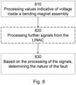
- the voltage values are processed.
- the values are derived from signals received from the first sensor and may be, for example, respective averages of signals received from the first sensor.
- the values may be determined by any of the device controller, the central controller, or the remote controller. Processing the values further comprises reviewing voltage values at a higher resolution than carried out in the methods described above, which may use the daily average voltage values.
- a review of voltage values for a single day of operation may be processed. It can be determined that the bending magnet voltage increases throughout the day's operation, and therefore that the cooling system is not functioning correctly. A fault can be determined as part of the cooling system.
- the processing of the values indicative of the voltage in the bending magnet assembly can comprise a review at a first data resolution, using for example the daily average values, and where the threshold criteria are met, further processing of the values at a second data resolution, for example looking at the development of bending magnet voltages across a single day.
- bending magnet voltage data is reviewed in correspondence with further signals obtained from the LINAC to determine a nature of the fault.
- gantry rotation angles can be split into 'bins', e.g. four bins between 0° and 90°, between 90° and 180°, between 180° and 270°, and between 270° and 360°. Voltage signals received while the gantry was at these angles are processed. For example, an average bending magnet voltage value can be determined for each bin.
- step 830 based on the processing of the signals or further signals, it is determined whether or not the nature of the fault is associated with, e.g. caused by, the cooling system of the bending magnet assembly.
- Outputting the nature of the fault may comprise displaying an indication of the nature of the fault on a display screen.
- the display may indicate that the fault either is, or isn't, associated with the bending magnet assembly.
- the method may comprise automatically issuing an alert identifying the nature of the fault to a field service engineer.
- the alert may comprise information identifying the machine at fault as well as the nature of the fault, along with information on recommended approaches to addressing and fixing the fault.
- Methods of the present disclosure allow a determination that the nature of a fault in a radiotherapy device, for example a clinical LINAC device, is associated with the bending magnet assembly.
- a radiotherapy device for example a clinical LINAC device
- Prior techniques can identify that a LINAC machine has a fault, but cannot provide any further information which may assist a field service engineer.
- the present methods allow both the identification of a fault, and a determination that the nature of the fault is associated with the bending magnet assembly, for example the bending magnet assembly cooling. The present techniques therefore describe a cost-effective and efficient method of determining a fault.
- Possible components which could be degrading, or operating at non-optimal performance, and which may cause faults that are broadly associated with the bending magnet assembly include one or more of the following components: the low voltage power supply units, the cooling system, and loose/flexing connections between the components which form the bending magnet assembly. The issue is not that these components may degrade to a level which may compromise patient safety, as the bending magnet assembly is monitored to ensure patient safety at all times. However, once it has been determined that a fault exists which is broadly associated with the bending magnet assembly it has to date proved difficult to identify which component is responsible.
- At least some of the present techniques generally involve processing signals from sensors which provide signals indicative of operating conditions at the bending magnet assembly and using the variation in signals to determine that an issue is likely associated with the bending magnet assembly of the LINAC device.
Landscapes
- Health & Medical Sciences (AREA)
- Engineering & Computer Science (AREA)
- Biomedical Technology (AREA)
- Physics & Mathematics (AREA)
- General Health & Medical Sciences (AREA)
- Radiology & Medical Imaging (AREA)
- Life Sciences & Earth Sciences (AREA)
- Animal Behavior & Ethology (AREA)
- Nuclear Medicine, Radiotherapy & Molecular Imaging (AREA)
- Public Health (AREA)
- Veterinary Medicine (AREA)
- Pathology (AREA)
- Optics & Photonics (AREA)
- Plasma & Fusion (AREA)
- Spectroscopy & Molecular Physics (AREA)
- Radiation-Therapy Devices (AREA)
Claims (12)
- Verfahren zum Bestimmen der Art eines Fehlers in einer Strahlentherapievorrichtung, die einen Linearbeschleuniger umfasst, wobei die Strahlentherapievorrichtung ausgestaltet ist, um einem Patienten therapeutische Strahlung bereitzustellen, wobei die Strahlentherapievorrichtung Folgendes umfasst:eine Ablenkmagnetbaugruppe (208), die dazu angeordnet ist, einen Elektronenstrahl auf ein Ziel zu richten, um die Strahlung zu produzieren; undeinen ersten Sensor (230), der ausgestaltet ist, um Signale bereitzustellen, die eine Spannung in einer ersten Region der Ablenkmagnetbaugruppe angeben; wobei das Verfahren Folgendes umfasst:Empfangen (610) von Spannungswerten, die von den Signalen von dem ersten Sensor abgeleitet sind;Verarbeiten (620) der Spannungswerte; wobei das Verarbeiten der Spannungswerte Bestimmen umfasst, ob die Spannungswerte mindestens ein Schwellenwertkriterium erfüllen; undbasierend auf dem Verarbeiten der Signale Bestimmen (630), ob die Art des Fehlers mit dem Ablenkmagneten in Zusammenhang steht,wobei das Bestimmen, ob die Spannungswerte das mindestens eine Schwellenwertkriterium erfüllen, ferner Folgendes umfasst: Bestimmen, ob sich die Spannungswerte in einem bestimmten Zeitraum um mindestens einen Schwellenbetrag geändert haben.
- Verfahren nach Anspruch 1, wobei das Bestimmen, ob die Spannungswerte das mindestens eine Schwellenwertkriterium erfüllen, Folgendes umfasst: Bestimmen, dass eine Differenz zwischen einem bestimmten Spannungswert und einem Referenzwert einen Referenzdifferenzwert überschritten hat.
- Verfahren nach einem der vorhergehenden Ansprüche, wobei das Bestimmen, ob die Spannungswerte das mindestens eine Schwellenwertkriterium erfüllen, ferner Folgendes umfasst:
Bestimmen, dass der bestimmte Spannungswert unter einen Schwellenspannungswert gefallen ist. - Verfahren nach einem der vorhergehenden Ansprüche, wobei das Verarbeiten der Spannungswerte Folgendes umfasst:Bestimmen, ob die Spannungswerte das mindestens eine Schwellenwertkriterium bei einer ersten Datenauflösung erfüllen, undin Reaktion darauf, dass das mindestens eine Schwellenwertkriterium erfüllt wird,Verarbeiten der Spannungswerte bei einer zweiten Datenauflösung.
- Verfahren nach Anspruch 4, wobei die zweite Datenauflösung höher als die erste Datenauflösung ist.
- Verfahren nach einem der vorhergehenden Ansprüche, wobei die Strahlentherapievorrichtung ferner Folgendes umfasst:
einen zweiten Sensor, der ausgestaltet ist, um Betriebssignale bereitzustellen, die einen Betriebsparameter der Strahlentherapievorrichtung angeben, wobei das Verfahren ferner Folgendes umfasst:Verarbeiten von Werten, die von den Betriebssignalen abgeleitet sind, in Reaktion auf die Bestimmung, dass der Spannungswert das Schwellenwertkriterium erfüllt,wobei das Bestimmen der Art des Fehlers Bestimmen einer Korrelation zwischen den Spannungswerten und den Betriebssignalen umfasst. - Verfahren nach Anspruch 6, wobei der Betriebsparameter eines von Folgendem ist:eine Bewegung einer Gantry der Strahlentherapievorrichtung;ein Rotationswinkel der Gantry der Strahlentherapievorrichtung;eine Temperatur an einer Verdrahtungsstelle der Strahlentherapievorrichtung;ein Betriebszustand der Strahlentherapievorrichtung und eine Strahlenergie des Elektronenstrahls.
- Verfahren nach einem der vorhergehenden Ansprüche, ferner umfassend Ausgeben der Art des Fehlers in der Strahlentherapievorrichtung.
- Verfahren nach Anspruch 7, wobei das Ausgeben der Art des Fehlers mindestens eines von Anzeigen einer Angabe der Art des Fehlers auf einem Anzeigebildschirm und/oder Ausgeben eines Alarms, der die Art des Fehlers identifiziert, an einen Außendiensttechniker umfasst.
- Verfahren nach einem der vorhergehenden Ansprüche, wobei die Strahlentherapievorrichtung ferner eine drehbare Gantry umfasst, an der eine Strahlungsquelle befestigt ist, wobei die Strahlungsquelle ausgestaltet ist, um einem Patienten die therapeutische Strahlung bereitzustellen, wobei das Verarbeiten des ersten Wertes und des Betriebsparameters ferner Bestimmen umfasst, dass das erste Signal und/oder der Betriebsparameter nicht von einem Rotationswinkel der Gantry abhängig sind.
- Computerlesbares Medium, umfassend computerausführbare Anweisungen, die bei Ausführung durch einen Prozessor bewirken, dass der Prozessor das Verfahren nach einem der vorhergehenden Ansprüche durchführt.
- System, umfassend:eine Fernbedienung (260);eine Zentralsteuerung (270); undeine Strahlentherapievorrichtung;wobei die Fernbedienung kommunikativ über ein Netzwerk an die Zentralsteuerung gekoppelt ist, wobei die Zentralsteuerung ausgestaltet ist, um Daten von der Strahlentherapievorrichtung zu empfangen, wobei die Strahlentherapievorrichtung einen Linearbeschleuniger umfasst, die Strahlentherapievorrichtung ausgestaltet ist, um einem Patienten therapeutische Strahlung bereitzustellen, und wobei die Strahlentherapievorrichtung Folgendes umfasst:eine Ablenkmagnetbaugruppe (208), die dazu angeordnet ist, einen Elektronenstrahl auf ein Ziel zu richten, um die Strahlung zu produzieren; undeinen ersten Sensor (230), wobei der erste Sensor ausgestaltet ist, um Signale bereitzustellen, die eine Spannung in einer ersten Region der Ablenkmagnetbaugruppe angeben;wobei die Fernbedienung ferner an ein computerlesbares Medium gekoppelt ist, das computerausführbare Anweisungen umfasst, die, wenn sie durch die Fernbedienung ausgeführt werden, die Fernbedienung zu Folgendem veranlassen:
Anfordern und Empfangen eines ersten Wertes, der von Signalen von dem ersten Sensor abgeleitet ist, von der Zentralsteuerung; und Durchführen des Verfahrens nach einem der Ansprüche 1 bis 10.
Applications Claiming Priority (2)
| Application Number | Priority Date | Filing Date | Title |
|---|---|---|---|
| GB1911178.0A GB2586133B (en) | 2019-08-05 | 2019-08-05 | Method for use with a Radiotherapy Device |
| PCT/EP2020/072066 WO2021023797A1 (en) | 2019-08-05 | 2020-08-05 | Method for use with a radiotherapy device |
Publications (2)
| Publication Number | Publication Date |
|---|---|
| EP4010073A1 EP4010073A1 (de) | 2022-06-15 |
| EP4010073B1 true EP4010073B1 (de) | 2025-02-26 |
Family
ID=67990850
Family Applications (1)
| Application Number | Title | Priority Date | Filing Date |
|---|---|---|---|
| EP20754205.1A Active EP4010073B1 (de) | 2019-08-05 | 2020-08-05 | Verfahren zur verwendung mit einer strahlentherapievorrichtung |
Country Status (6)
| Country | Link |
|---|---|
| US (1) | US20220280814A1 (de) |
| EP (1) | EP4010073B1 (de) |
| CN (1) | CN115175733A (de) |
| AU (1) | AU2020325590B2 (de) |
| GB (1) | GB2586133B (de) |
| WO (1) | WO2021023797A1 (de) |
Family Cites Families (7)
| Publication number | Priority date | Publication date | Assignee | Title |
|---|---|---|---|---|
| US5017789A (en) * | 1989-03-31 | 1991-05-21 | Loma Linda University Medical Center | Raster scan control system for a charged-particle beam |
| US6212256B1 (en) * | 1998-11-25 | 2001-04-03 | Ge Medical Global Technology Company, Llc | X-ray tube replacement management system |
| US6498444B1 (en) * | 2000-04-10 | 2002-12-24 | Siemens Medical Solutions Usa, Inc. | Computer-aided tuning of charged particle accelerators |
| JP3705091B2 (ja) * | 2000-07-27 | 2005-10-12 | 株式会社日立製作所 | 医療用加速器システム及びその運転方法 |
| JP3859605B2 (ja) * | 2003-03-07 | 2006-12-20 | 株式会社日立製作所 | 粒子線治療システム及び粒子線出射方法 |
| DE102005023166B4 (de) * | 2005-05-19 | 2007-09-27 | Siemens Ag | Verfahren zur Funktionsüberwachung bei medizinischen Beschleunigereinrichtungen sowie medizinische Beschleunigungseinrichtung |
| US10297414B2 (en) * | 2016-09-20 | 2019-05-21 | Varex Imaging Corporation | X-ray tube devices and methods for imaging systems |
-
2019
- 2019-08-05 GB GB1911178.0A patent/GB2586133B/en active Active
-
2020
- 2020-08-05 US US17/632,748 patent/US20220280814A1/en not_active Abandoned
- 2020-08-05 CN CN202080069779.6A patent/CN115175733A/zh active Pending
- 2020-08-05 EP EP20754205.1A patent/EP4010073B1/de active Active
- 2020-08-05 WO PCT/EP2020/072066 patent/WO2021023797A1/en not_active Ceased
- 2020-08-05 AU AU2020325590A patent/AU2020325590B2/en active Active
Also Published As
| Publication number | Publication date |
|---|---|
| GB2586133B (en) | 2021-11-17 |
| CN115175733A (zh) | 2022-10-11 |
| GB201911178D0 (en) | 2019-09-18 |
| AU2020325590A1 (en) | 2022-02-24 |
| EP4010073A1 (de) | 2022-06-15 |
| WO2021023797A1 (en) | 2021-02-11 |
| AU2020325590B2 (en) | 2025-09-04 |
| US20220280814A1 (en) | 2022-09-08 |
| GB2586133A (en) | 2021-02-10 |
Similar Documents
| Publication | Publication Date | Title |
|---|---|---|
| US12397176B2 (en) | Method for use with a radiotherapy device | |
| US11565132B2 (en) | Method for use with a radiotherapy device | |
| JP5668000B2 (ja) | ビームモニタシステム及び粒子線照射システム | |
| CN117256202A (zh) | 改进x射线管的灯丝故障预测的系统和方法 | |
| JP6095117B2 (ja) | ビームモニタシステムおよび粒子線照射システム | |
| AU2020325590B2 (en) | Method for use with a radiotherapy device | |
| JP2020012691A (ja) | 異常予兆診断システム及び異常予兆診断方法 | |
| EP3939392B1 (de) | Verfahren zur bestimmung, ob eine reparatur oder ein austausch eines magnetrons eines linearbeschleunigers für die strahlentherapie geplant werden sollte, und computerlesbares medium zur durchführung des verfahrens | |
| US12161884B2 (en) | Methods for use with a component of a beam limiting device | |
| US11058897B2 (en) | System and method for detecting hardware degradation in a radiation therapy system | |
| CN108848605B (zh) | 加速器的径向插入靶装置 | |
| EP4474010A1 (de) | Verfahren zur verwendung mit einer strahlentherapievorrichtung | |
| JP2023071440A (ja) | 粒子線治療システム、照射制御装置及び照射制御方法 | |
| US20230376652A1 (en) | Magnetron maintenance | |
| CN116634649A (zh) | 加速器腔体老练装置及方法、电子设备、相关装置 |
Legal Events
| Date | Code | Title | Description |
|---|---|---|---|
| STAA | Information on the status of an ep patent application or granted ep patent |
Free format text: STATUS: UNKNOWN |
|
| STAA | Information on the status of an ep patent application or granted ep patent |
Free format text: STATUS: THE INTERNATIONAL PUBLICATION HAS BEEN MADE |
|
| PUAI | Public reference made under article 153(3) epc to a published international application that has entered the european phase |
Free format text: ORIGINAL CODE: 0009012 |
|
| STAA | Information on the status of an ep patent application or granted ep patent |
Free format text: STATUS: REQUEST FOR EXAMINATION WAS MADE |
|
| 17P | Request for examination filed |
Effective date: 20220304 |
|
| AK | Designated contracting states |
Kind code of ref document: A1 Designated state(s): AL AT BE BG CH CY CZ DE DK EE ES FI FR GB GR HR HU IE IS IT LI LT LU LV MC MK MT NL NO PL PT RO RS SE SI SK SM TR |
|
| DAV | Request for validation of the european patent (deleted) | ||
| DAX | Request for extension of the european patent (deleted) | ||
| GRAP | Despatch of communication of intention to grant a patent |
Free format text: ORIGINAL CODE: EPIDOSNIGR1 |
|
| STAA | Information on the status of an ep patent application or granted ep patent |
Free format text: STATUS: GRANT OF PATENT IS INTENDED |
|
| INTG | Intention to grant announced |
Effective date: 20240917 |
|
| GRAS | Grant fee paid |
Free format text: ORIGINAL CODE: EPIDOSNIGR3 |
|
| GRAA | (expected) grant |
Free format text: ORIGINAL CODE: 0009210 |
|
| STAA | Information on the status of an ep patent application or granted ep patent |
Free format text: STATUS: THE PATENT HAS BEEN GRANTED |
|
| AK | Designated contracting states |
Kind code of ref document: B1 Designated state(s): AL AT BE BG CH CY CZ DE DK EE ES FI FR GB GR HR HU IE IS IT LI LT LU LV MC MK MT NL NO PL PT RO RS SE SI SK SM TR |
|
| REG | Reference to a national code |
Ref country code: GB Ref legal event code: FG4D |
|
| REG | Reference to a national code |
Ref country code: CH Ref legal event code: EP |
|
| P01 | Opt-out of the competence of the unified patent court (upc) registered |
Free format text: CASE NUMBER: APP_7171/2025 Effective date: 20250212 |
|
| REG | Reference to a national code |
Ref country code: DE Ref legal event code: R096 Ref document number: 602020046779 Country of ref document: DE |
|
| REG | Reference to a national code |
Ref country code: IE Ref legal event code: FG4D |
|
| REG | Reference to a national code |
Ref country code: NL Ref legal event code: MP Effective date: 20250226 |
|
| PG25 | Lapsed in a contracting state [announced via postgrant information from national office to epo] |
Ref country code: RS Free format text: LAPSE BECAUSE OF FAILURE TO SUBMIT A TRANSLATION OF THE DESCRIPTION OR TO PAY THE FEE WITHIN THE PRESCRIBED TIME-LIMIT Effective date: 20250526 |
|
| PG25 | Lapsed in a contracting state [announced via postgrant information from national office to epo] |
Ref country code: FI Free format text: LAPSE BECAUSE OF FAILURE TO SUBMIT A TRANSLATION OF THE DESCRIPTION OR TO PAY THE FEE WITHIN THE PRESCRIBED TIME-LIMIT Effective date: 20250226 |
|
| PG25 | Lapsed in a contracting state [announced via postgrant information from national office to epo] |
Ref country code: PL Free format text: LAPSE BECAUSE OF FAILURE TO SUBMIT A TRANSLATION OF THE DESCRIPTION OR TO PAY THE FEE WITHIN THE PRESCRIBED TIME-LIMIT Effective date: 20250226 |
|
| PG25 | Lapsed in a contracting state [announced via postgrant information from national office to epo] |
Ref country code: ES Free format text: LAPSE BECAUSE OF FAILURE TO SUBMIT A TRANSLATION OF THE DESCRIPTION OR TO PAY THE FEE WITHIN THE PRESCRIBED TIME-LIMIT Effective date: 20250226 |
|
| PGFP | Annual fee paid to national office [announced via postgrant information from national office to epo] |
Ref country code: GB Payment date: 20250612 Year of fee payment: 6 |
|
| REG | Reference to a national code |
Ref country code: LT Ref legal event code: MG9D |
|
| PG25 | Lapsed in a contracting state [announced via postgrant information from national office to epo] |
Ref country code: IS Free format text: LAPSE BECAUSE OF FAILURE TO SUBMIT A TRANSLATION OF THE DESCRIPTION OR TO PAY THE FEE WITHIN THE PRESCRIBED TIME-LIMIT Effective date: 20250626 Ref country code: NO Free format text: LAPSE BECAUSE OF FAILURE TO SUBMIT A TRANSLATION OF THE DESCRIPTION OR TO PAY THE FEE WITHIN THE PRESCRIBED TIME-LIMIT Effective date: 20250526 |
|
| PG25 | Lapsed in a contracting state [announced via postgrant information from national office to epo] |
Ref country code: NL Free format text: LAPSE BECAUSE OF FAILURE TO SUBMIT A TRANSLATION OF THE DESCRIPTION OR TO PAY THE FEE WITHIN THE PRESCRIBED TIME-LIMIT Effective date: 20250226 |
|
| PG25 | Lapsed in a contracting state [announced via postgrant information from national office to epo] |
Ref country code: HR Free format text: LAPSE BECAUSE OF FAILURE TO SUBMIT A TRANSLATION OF THE DESCRIPTION OR TO PAY THE FEE WITHIN THE PRESCRIBED TIME-LIMIT Effective date: 20250226 |
|
| PG25 | Lapsed in a contracting state [announced via postgrant information from national office to epo] |
Ref country code: PT Free format text: LAPSE BECAUSE OF FAILURE TO SUBMIT A TRANSLATION OF THE DESCRIPTION OR TO PAY THE FEE WITHIN THE PRESCRIBED TIME-LIMIT Effective date: 20250626 Ref country code: LV Free format text: LAPSE BECAUSE OF FAILURE TO SUBMIT A TRANSLATION OF THE DESCRIPTION OR TO PAY THE FEE WITHIN THE PRESCRIBED TIME-LIMIT Effective date: 20250226 |
|
| PGFP | Annual fee paid to national office [announced via postgrant information from national office to epo] |
Ref country code: FR Payment date: 20250610 Year of fee payment: 6 |
|
| PG25 | Lapsed in a contracting state [announced via postgrant information from national office to epo] |
Ref country code: GR Free format text: LAPSE BECAUSE OF FAILURE TO SUBMIT A TRANSLATION OF THE DESCRIPTION OR TO PAY THE FEE WITHIN THE PRESCRIBED TIME-LIMIT Effective date: 20250527 Ref country code: BG Free format text: LAPSE BECAUSE OF FAILURE TO SUBMIT A TRANSLATION OF THE DESCRIPTION OR TO PAY THE FEE WITHIN THE PRESCRIBED TIME-LIMIT Effective date: 20250226 |
|
| REG | Reference to a national code |
Ref country code: AT Ref legal event code: MK05 Ref document number: 1770078 Country of ref document: AT Kind code of ref document: T Effective date: 20250226 |
|
| PG25 | Lapsed in a contracting state [announced via postgrant information from national office to epo] |
Ref country code: SE Free format text: LAPSE BECAUSE OF FAILURE TO SUBMIT A TRANSLATION OF THE DESCRIPTION OR TO PAY THE FEE WITHIN THE PRESCRIBED TIME-LIMIT Effective date: 20250226 |
|
| RAP4 | Party data changed (patent owner data changed or rights of a patent transferred) |
Owner name: ELEKTA LIMITED |
|
| PG25 | Lapsed in a contracting state [announced via postgrant information from national office to epo] |
Ref country code: SM Free format text: LAPSE BECAUSE OF FAILURE TO SUBMIT A TRANSLATION OF THE DESCRIPTION OR TO PAY THE FEE WITHIN THE PRESCRIBED TIME-LIMIT Effective date: 20250226 |
|
| PG25 | Lapsed in a contracting state [announced via postgrant information from national office to epo] |
Ref country code: DK Free format text: LAPSE BECAUSE OF FAILURE TO SUBMIT A TRANSLATION OF THE DESCRIPTION OR TO PAY THE FEE WITHIN THE PRESCRIBED TIME-LIMIT Effective date: 20250226 |
|
| PGFP | Annual fee paid to national office [announced via postgrant information from national office to epo] |
Ref country code: DE Payment date: 20250611 Year of fee payment: 6 |
|
| PG25 | Lapsed in a contracting state [announced via postgrant information from national office to epo] |
Ref country code: IT Free format text: LAPSE BECAUSE OF FAILURE TO SUBMIT A TRANSLATION OF THE DESCRIPTION OR TO PAY THE FEE WITHIN THE PRESCRIBED TIME-LIMIT Effective date: 20250226 |
|
| PG25 | Lapsed in a contracting state [announced via postgrant information from national office to epo] |
Ref country code: AT Free format text: LAPSE BECAUSE OF FAILURE TO SUBMIT A TRANSLATION OF THE DESCRIPTION OR TO PAY THE FEE WITHIN THE PRESCRIBED TIME-LIMIT Effective date: 20250226 |
|
| PG25 | Lapsed in a contracting state [announced via postgrant information from national office to epo] |
Ref country code: EE Free format text: LAPSE BECAUSE OF FAILURE TO SUBMIT A TRANSLATION OF THE DESCRIPTION OR TO PAY THE FEE WITHIN THE PRESCRIBED TIME-LIMIT Effective date: 20250226 Ref country code: CZ Free format text: LAPSE BECAUSE OF FAILURE TO SUBMIT A TRANSLATION OF THE DESCRIPTION OR TO PAY THE FEE WITHIN THE PRESCRIBED TIME-LIMIT Effective date: 20250226 |
|
| PG25 | Lapsed in a contracting state [announced via postgrant information from national office to epo] |
Ref country code: RO Free format text: LAPSE BECAUSE OF FAILURE TO SUBMIT A TRANSLATION OF THE DESCRIPTION OR TO PAY THE FEE WITHIN THE PRESCRIBED TIME-LIMIT Effective date: 20250226 |
|
| PG25 | Lapsed in a contracting state [announced via postgrant information from national office to epo] |
Ref country code: SK Free format text: LAPSE BECAUSE OF FAILURE TO SUBMIT A TRANSLATION OF THE DESCRIPTION OR TO PAY THE FEE WITHIN THE PRESCRIBED TIME-LIMIT Effective date: 20250226 |
|
| REG | Reference to a national code |
Ref country code: DE Ref legal event code: R097 Ref document number: 602020046779 Country of ref document: DE |
|
| PLBE | No opposition filed within time limit |
Free format text: ORIGINAL CODE: 0009261 |
|
| STAA | Information on the status of an ep patent application or granted ep patent |
Free format text: STATUS: NO OPPOSITION FILED WITHIN TIME LIMIT |
|
| REG | Reference to a national code |
Ref country code: CH Ref legal event code: L10 Free format text: ST27 STATUS EVENT CODE: U-0-0-L10-L00 (AS PROVIDED BY THE NATIONAL OFFICE) Effective date: 20260107 |
|
| 26N | No opposition filed |
Effective date: 20251127 |
|
| REG | Reference to a national code |
Ref country code: CH Ref legal event code: H13 Free format text: ST27 STATUS EVENT CODE: U-0-0-H10-H13 (AS PROVIDED BY THE NATIONAL OFFICE) Effective date: 20260324 |
|
| PG25 | Lapsed in a contracting state [announced via postgrant information from national office to epo] |
Ref country code: MC Free format text: LAPSE BECAUSE OF FAILURE TO SUBMIT A TRANSLATION OF THE DESCRIPTION OR TO PAY THE FEE WITHIN THE PRESCRIBED TIME-LIMIT Effective date: 20250226 |
|
| PG25 | Lapsed in a contracting state [announced via postgrant information from national office to epo] |
Ref country code: LU Free format text: LAPSE BECAUSE OF NON-PAYMENT OF DUE FEES Effective date: 20250805 |
|
| PG25 | Lapsed in a contracting state [announced via postgrant information from national office to epo] |
Ref country code: CH Free format text: LAPSE BECAUSE OF NON-PAYMENT OF DUE FEES Effective date: 20250831 |