EP4009758A1 - Automatic conveyance apparatus and production system comprising same - Google Patents
Automatic conveyance apparatus and production system comprising same Download PDFInfo
- Publication number
- EP4009758A1 EP4009758A1 EP19939175.6A EP19939175A EP4009758A1 EP 4009758 A1 EP4009758 A1 EP 4009758A1 EP 19939175 A EP19939175 A EP 19939175A EP 4009758 A1 EP4009758 A1 EP 4009758A1
- Authority
- EP
- European Patent Office
- Prior art keywords
- loading
- loading surface
- inclination
- height
- conveyance apparatus
- Prior art date
- Legal status (The legal status is an assumption and is not a legal conclusion. Google has not performed a legal analysis and makes no representation as to the accuracy of the status listed.)
- Granted
Links
Images





Classifications
-
- H—ELECTRICITY
- H05—ELECTRIC TECHNIQUES NOT OTHERWISE PROVIDED FOR
- H05K—PRINTED CIRCUITS; CASINGS OR CONSTRUCTIONAL DETAILS OF ELECTRIC APPARATUS; MANUFACTURE OF ASSEMBLAGES OF ELECTRICAL COMPONENTS
- H05K13/00—Apparatus or processes specially adapted for manufacturing or adjusting assemblages of electric components
- H05K13/02—Feeding of components
- H05K13/021—Loading or unloading of containers
-
- H—ELECTRICITY
- H05—ELECTRIC TECHNIQUES NOT OTHERWISE PROVIDED FOR
- H05K—PRINTED CIRCUITS; CASINGS OR CONSTRUCTIONAL DETAILS OF ELECTRIC APPARATUS; MANUFACTURE OF ASSEMBLAGES OF ELECTRICAL COMPONENTS
- H05K13/00—Apparatus or processes specially adapted for manufacturing or adjusting assemblages of electric components
- H05K13/0084—Containers and magazines for components, e.g. tube-like magazines
-
- H—ELECTRICITY
- H05—ELECTRIC TECHNIQUES NOT OTHERWISE PROVIDED FOR
- H05K—PRINTED CIRCUITS; CASINGS OR CONSTRUCTIONAL DETAILS OF ELECTRIC APPARATUS; MANUFACTURE OF ASSEMBLAGES OF ELECTRICAL COMPONENTS
- H05K13/00—Apparatus or processes specially adapted for manufacturing or adjusting assemblages of electric components
- H05K13/04—Mounting of components, e.g. of leadless components
- H05K13/0404—Pick-and-place heads or apparatus, e.g. with jaws
- H05K13/0408—Incorporating a pick-up tool
-
- H—ELECTRICITY
- H05—ELECTRIC TECHNIQUES NOT OTHERWISE PROVIDED FOR
- H05K—PRINTED CIRCUITS; CASINGS OR CONSTRUCTIONAL DETAILS OF ELECTRIC APPARATUS; MANUFACTURE OF ASSEMBLAGES OF ELECTRICAL COMPONENTS
- H05K13/00—Apparatus or processes specially adapted for manufacturing or adjusting assemblages of electric components
- H05K13/08—Monitoring manufacture of assemblages
- H05K13/0882—Control systems for mounting machines or assembly lines, e.g. centralized control, remote links, programming of apparatus and processes as such
Definitions
- the technique disclosed in the present specification relates to an automatic conveyance apparatus and a production system including the same.
- Patent Literature 1 International Publication No. WO2018/173204 discloses a moving robot used as an automatic conveyance apparatus.
- the moving robot is used in a factory provided with multiple production devices for producing a specific object.
- the moving robot can convey a member used in the production device in a state in which the member is loaded on a loading surface (hereinafter, referred to as a first loading surface) in the moving robot, deliver the conveyed member from the first loading surface to, for example, a supplying surface (hereinafter, referred to as a second loading surface) provided in the production device, and pick up a member used in the production device from the second loading surface to the first loading surface.
- a loading surface hereinafter, referred to as a first loading surface
- a second loading surface supplying surface
- the moving robot of Patent Literature 1 stops in front of the production device and delivers the member on the supplying surface by moving the member in the front-rear direction on the first loading surface.
- the height or the inclination of the first loading surface does not change only by moving the member in the front-rear direction. Accordingly, for example, when a floor surface of a factory where the production device is provided is not flat since the height or the inclination of the second loading surface and the first loading surface do not always match, it can be difficult to move the member from the first loading surface to the second loading surface. The same can be applied when the member is picked up from the second loading surface to the first loading surface.
- the present specification discloses an automatic conveyance apparatus.
- the automatic conveyance apparatus is employed together with a loading table for loading a member supplied from outside and a production device for producing a specific object by using the member loaded on the loading table, delivers the member before being used on the loading table, and picks up the member after being used from the loading table.
- the automatic conveyance apparatus includes a first loading surface, an adjustment device, a movement device, and a control section.
- the first loading surface is capable of loading the member.
- the adjustment device adjusts a height and an inclination of the first loading surface in accordance with a height position and an inclination position of a second loading surface provided on the loading table on which the member is loaded.
- the movement device moves the member from the first loading surface to the second loading surface and/or from the second loading surface to the first loading surface.
- the control section drives the movement device to move the member between the first loading surface and the second loading surface when the automatic conveyance apparatus is positioned at a member delivery position and/or a member pickup position where the automatic conveyance apparatus delivers and/or picks up the member and when the height and the inclination of the first loading surface are adjusted in accordance with the height position and the inclination position of the second loading surface by the adjustment device.
- the automatic conveyance apparatus is configured to travel between multiple predetermined positions including the member delivery position and/or the member pickup position.
- the automatic conveyance apparatus described above includes the adjustment device that adjusts the height and the inclination of the first loading surface of the automatic conveyance apparatus in accordance with the height position and the inclination position of the second loading surface of the loading table on which the member is loaded. Accordingly, the automatic conveyance apparatus can adjust the height and the inclination of the first loading surface in accordance with the second loading surface by the adjustment device even when, for example, a floor surface of a factory is not flat. As a result, the automatic conveyance apparatus can reliably move the member from the first loading surface to the second loading surface and/or from the second loading surface to the first loading surface.
- the present specification discloses a production system.
- the production system includes a loading table capable of loading a member supplied from outside, a production device configured to produce a specific object by using the member loaded on the loading table, and an automatic conveyance apparatus configured to deliver the member before being used and/or after being used on the loading table and pick up the member before being used and/or after being used.
- the automatic conveyance apparatus includes a first loading surface capable of loading the member and is configured to travel between multiple predetermined positions including a member delivery position and/or a member pickup position.
- the loading table includes a second loading surface capable of loading the member.
- the production system further includes an adjustment device, a movement device, and a control section.
- the adjustment device adjusts a height and an inclination of the first loading surface in accordance with a height position and an inclination position of the second loading surface.
- the movement device moves the member from the first loading surface to the second loading surface and/or from the second loading surface to the first loading surface.
- the control section drives the movement device to move the member between the first loading surface and the second loading surface when the automatic conveyance apparatus is positioned at the member delivery position and/or the member pickup position and when the height and the inclination of the first loading surface are adjusted in accordance with the height position and the inclination position of the second loading surface by the adjustment device.
- the production system described above includes the adjustment device that adjusts the height and the inclination of the first loading surface of the automatic conveyance apparatus in accordance with the height position and the inclination position of the second loading surface of the loading table on which the member is loaded.
- the automatic conveyance apparatus can reliably move the member from the first loading surface to the second loading surface and/or from the second loading surface to the first loading surface even when, for example, a floor surface of a factory is not flat.
- the movement device may move the member along the first loading surface and the second loading surface in a sliding manner when the height and the inclination of the first loading surface are adjusted in accordance with the height position and the inclination position of the second loading surface by the adjustment device.
- the member can be moved between the first loading surface and the second loading surface by merely sliding the member, and the configuration of the automatic conveyance apparatus (in particular, the movement device) can be simplified.
- the production system may include the automatic conveyance apparatus described above, a loading table provided with the second loading surface capable of loading the member, a production device configured to produce a specific object by using the member loaded on the loading table, a memory section configured to store reference position data including a reference height position and a reference inclination position of the second loading surface with respect to a reference surface set in advance, and a measurement section configured to measure a height position and an inclination position of the first loading surface with respect to the reference surface.
- the adjustment device may adjust the height and the inclination of the first loading surface based on the reference position data stored in the memory section and the height position and the inclination position of the first loading surface measured by the measurement section.
- the height and the inclination of the first loading surface can be adjusted based on these data.
- the production system may include multiple loading tables provided with the second loading surface capable of loading the member.
- the memory section may store the reference position data of the second loading surface of the loading table for each of the multiple loading tables, and when the automatic conveyance apparatus is positioned at the member delivery position and/or the member pickup position of a specific loading table among the multiple loading tables, the adjustment device may adjust the height and the inclination of the first loading surface based on the reference position data of the specific loading table and the height position and the inclination position of the first loading surface measured by the measurement section. According to such a configuration, by storing the reference position data of the multiple loading tables, the height and the inclination of the first loading surface can be adjusted with respect to each of the loading tables.
- the production device may be a component mounter configured to mount a component on a board
- the member may be a component supply feeder configured to supply the component to the component mounter.
- the specific configuration of the component supply feeder is not particularly limited and may be a tape type feeder that accommodates multiple components on a wound tape, a tray type feeder that accommodates multiple components on a tray, or a bulk type feeder that randomly accommodates multiple components in a container.
- production system 100 includes management device 6, multiple component mounting machines 30, multiple AGVs 10, and storage container 50.
- Management device 6 is communicably connected to each of component mounting machines 30, each of AGVs 10, and storage container 50 in a bidirectional manner.
- Management device 6 controls operations of multiple component mounting machines 30, multiple AGVs 10, and storage container 50, and manages the entire mounting line.
- AGV 10 is an example of an automatic conveyance apparatus according to the technique disclosed in the present specification and conveys component supply feeder 40 between multiple component mounting machines 30 and storage container 50.
- multiple stop positions P1 to P5 which include multiple delivery positions/pickup positions for delivering and/or picking up component supply feeder 40 to/from each of component mounting machines 30 and storage container 50, are set.
- AGV 10 is configured to travel between multiple set stop positions (PI to P5) and delivers and/or picks up component supply feeder 40 to/from component mounting machine 30 or storage container 50 (refer to Fig. 1 ).
- multiple component mounting machines 30 are arranged side by side in the x-direction, the number of component mounting machines 30 and the arrangement thereof to be arranged are not particularly limited.
- component mounting machine 30 on which component supply feeder 40 is installed will be described with reference to Figs. 3 and 4 .
- component mounting machine 30 includes multiple component supply feeders 40, device pallet 42, feeder installation table 44, mounting head 34, head movement device 36, board conveyor 38, touch panel 46, and mounting machine control device 48.
- Each of component supply feeders 40 accommodates multiple components 4.
- device pallet 42 has a general plate shape and has upper surface 42a and lower surface 42b positioned on the opposite side of upper surface 42a. Upper surface 42a of device pallet 42 can install multiple component supply feeders 40 in an attachable and detachable manner.
- Device pallet 42 is attached on upper surface 44a of feeder installation table 44 in an attachable and detachable manner.
- component supply feeder 40 By attaching device pallet 42 on which component supply feeder 40 is installed on upper surface 44a of feeder installation table 44, component supply feeder 40 is capable of supplying component 4 to mounting head 34.
- Upper surface 44a of feeder installation table 44 is an example of a second loading surface according to the technique disclosed in the present specification.
- Mounting head 34 holds one or multiple suction nozzles 32 in an attachable and detachable manner, picks up component 4 supplied by component supply feeder 40 by using suction nozzles 32, and mounts component 4 on board 2.
- head movement device 36 moves mounting head 34 with respect to component supply feeder 40 and board 2.
- component 4 is picked up from a specific component supply feeder 40 among multiple component supply feeders 40 so that component 4 is mounted on a position of board 2 set in advance.
- Board conveyor 38 loads, supports, and unloads board 2 along the x-direction.
- Touch panel 46 is a display device that provides an operator with various information of component mounting machine 30, as well as an input device that receives commands or information from the operator.
- Mounting machine control device 48 is configured with a computer including a CPU and a storage device. Mounting machine control device 48 is communicably connected to management device 6. Mounting machine control device 48 controls the operation of each section of component mounting machine 30 based on a production program transmitted from management device 6.
- AGV 10 that conveys component supply feeder 40 will be described with reference to Figs. 2 , 6 , and 7 .
- AGV 10 picks up multiple component supply feeders 40 before being used from storage container 50 and delivers component supply feeder 40 before being used to component mounting machine 30 (that is, feeder installation table 44).
- AGV 10 picks up component supply feeder 40 after being used from feeder installation table 44 of component mounting machine 30.
- AGV 10 includes vehicle body 11, wheels 17, adjustment device 14, feeder movement device 16, drive device 18, and control device 12 that controls each section of AGV 10.
- Vehicle body 11 includes vehicle body main body 11a that rotatably supports wheels 17, and pallet holding section 13 disposed on vehicle body main body 11a via adjustment device 14.
- Pallet holding section 13 has a pair of loading surfaces 13a arranged at intervals in the width direction of vehicle body 11.
- Component supply feeder 40 is configured to be loadable on the pair of loading surfaces 13a together with device pallet 42. That is, the pair of loading surfaces 13a supports both ends 42c of lower surface 42b of device pallet 42. Further, feeder movement device 16 is provided on each of loading surfaces 13a.
- Feeder movement device 16 is a device that moves component supply feeder 40 from loading surface 13a, for example, to upper surface 44a of feeder installation table 44 of component mounting machine 30 and is driven by control device 12. Specifically, the movement device moves component supply feeder 40 along the pair of loading surfaces 13a and upper surface 44a of feeder installation table 44 in a sliding manner.
- the feeder movement device 16 has a pair of cylinder sections 16a. Each of the pair of cylinder sections 16a is provided with a piston mechanism.
- a catch mechanism (not shown) is provided at distal end 16b of each cylinder section 16a. The catch mechanism is configured to be capable of gripping end section 42d of device pallet 42.
- feeder movement device 16 can move device pallet 42, that is, component supply feeder 40 in the front-rear direction of vehicle body 11. After device pallet 42 is moved to a predetermined position on the pair of loading surfaces 13a or a predetermined position on upper surface 44a of feeder installation table 44, the gripping of device pallet 42 by feeder movement device 16 is released, so that device pallet 42 is released from feeder movement device 16. As a result, AGV 10 can deliver component supply feeder 40 to component mounting machine 30 or storage container 50 or can pick up component supply feeder 40 from component mounting machine 30 or storage container 50.
- feeder movement device 16 moves component supply feeder 40 (more specifically, device pallet 42) between loading surface 13a and upper surface 44a of feeder installation table 44 in a sliding manner. Therefore, component supply feeder 40 can be moved with a small amount of power and the configuration of AGV 10 can be simplified.
- Adjustment device 14 is a device, which is disposed between vehicle body main body 11a and pallet holding section 13 and adjusts the height and the inclination of loading surface 13a of pallet holding section 13, for example, in accordance with the height position and the inclination position of upper surface 44a of feeder installation table 44 of component mounting machine 30, and is driven by control device 12.
- Adjustment device 14 includes an actuator (not shown) and can adjust the position and the inclination (the inclination of vehicle body 11 in the front-rear direction ( ⁇ in Fig. 6 ) and the inclination in the left-right direction) of the pair of loading surfaces 13a in the up-down direction.
- Adjustment device 14 includes a detection section that detects the drive amount of the actuator and can adjust the pair of loading surfaces 13a to the desired height position and the desired inclination position by controlling the drive amount, which is detected by the detection section, to a target drive amount. Accordingly, the detection section that detects the drive amount of the actuator of adjustment device 14 serves as a measurement section that measures the height and the inclination of loading surface 13a. A well-known mechanism for adjusting the height and the inclination of the loading surface can be used as adjustment device 14.
- Drive device 18 is a device that drives wheels 17 to cause AGV 10 to travel and is driven by control device 12.
- Drive device 18 is configured to be capable of independently driving left and right wheels 17, capable of causing AGV 10 to travel in the front-rear direction, and capable of freely adjusting the advancing direction of AGV 10. Accordingly, AGV 10 can be stopped at any designated position and in any direction.
- Control device 12 controls feeder movement device 16, adjustment device 14, and drive device 18.
- Control device 12 is constituted by a computer including a CPU, a ROM, and a RAM.
- Control device 12 includes control section 12a and memory section 12b, and various functions are assigned to control device 12 by executing a program installed in advance.
- control device 12 serves as control section 12a that performs a process of driving feeder movement device 16 to move component supply feeder 40 from loading surface 13a, a process of driving adjustment device 14 to adjust the height and the inclination positions of loading surface 13a, and a process of driving drive device 18 to cause AGV 10 to travel to any position.
- Control device 12 stores, for example, a command transmitted from management device 6, and also serves as memory section 12b that stores a map in the factory.
- the map referred to herein includes stop positions P1 to P4 set for each component mounting machine 30, and stop position P0 set for storage container 50 or stop position P5 (also referred to as discharge position P5) for discharging component supply feeder 40 after being used to discharge place 54 (refer to Fig. 1 ).
- AGV 10 includes interface 20.
- AGV 10 is communicably (e.g., wirelessly) connected to management device 6 in a bidirectional manner, and the command from management device 6 can be received via interface 20.
- Storage container 50 will be described with reference to Fig. 8 .
- Storage container 50 stores multiple component supply feeders 40 before being used in component mounting machine 30.
- storage container 50 includes feeder installation table 52.
- Device pallet 42 to which multiple component supply feeders 40 are attached is configured to be loadable on upper surface 52a of feeder installation table 52.
- Storage container 50 is communicably connected to management device 6.
- management device 6 As an example, storage container 50 installs device pallet 42, to which component supply feeder 40 designated in response to the command from management device 6 is attached, on upper surface 52a of feeder installation table 52. Further, storage container 50 reports an inventory status of component supply feeder 40 in storage container 50 to management device 6.
- Management device 6 will be described with reference to Fig. 2 .
- Management device 6 is communicably connected to each of component mounting machines 30, each of the AGVs 10, and storage container 50, and manages all of these devices.
- Management device 6 is constituted by a computer including a CPU, a ROM, and a RAM.
- management device 6 includes memory section 6a and command section 6b, and various functions are assigned to management device 6 by executing the program installed in advance.
- management device 6 stores reference position data of each of component mounting machines 30 with respect to a reference surface set in advance and also serves as memory section 6a that stores a production plan in the factory.
- the reference position data includes a reference height position and a reference inclination position with respect to the reference surface for upper surface 44a of feeder installation table 44 of each component mounting machine 30.
- Management device 6 serves as command section 6b that transmits the command for controlling each component mounting machine 30, each AGV 10, and storage container 50 based on the stored production plan, to each of component mounting machines 30, AGVs 10, and storage container 50.
- the floor surface of the factory in which production system 100 described above is provided may be uneven. Therefore, the heights or the inclinations between upper surface 44a of feeder installation table 44 of component mounting machine 30 and loading surface 13a of AGV 10 do not necessarily match each other. Therefore, it may be difficult to deliver component supply feeder 40 to upper surface 44a of feeder installation table 44 of component mounting machine 30 by simply moving component supply feeder 40 from loading surface 13a in the front-rear direction in a sliding manner. The same can be applied when the member is picked up from upper surface 44a of feeder installation table 44 to loading surface 13a of AGV 10.
- AGV 10 includes, for example, adjustment device 14 that adjusts the height and the inclination of loading surface 13a of AGV 10 in accordance with the height position and the inclination position of upper surface 44a of feeder installation table 44 of component mounting machine 30. Accordingly, in AGV 10, even when the floor surface of the factory is uneven, the height and the inclination of loading surface 13a of AGV 10 can be adjusted in accordance with upper surface 44a of feeder installation table 44 by adjustment device 14. As a result, AGV 10 can reliably move the member from loading surface 13a to upper surface 44a of feeder installation table 44 of component mounting machine 30 and/or from upper surface 44a of feeder installation table 44 to loading surface 13a of AGV 10.
- Upper surface 44a of feeder installation table 52 of component mounting machine 30 is an example of the second loading surface of the loading table in the technique disclosed in the present specification.
- the second loading surface of the loading table is not limited to this and may be, for example, upper surface 52a of feeder installation table 52 of storage container 50.
- management device 6 includes measurement section 6c and measurement device 60.
- AGV 10 performs advance preparation before the delivery and picking up of device pallet 42.
- the advance preparation will be described with reference to Fig. 9 .
- Measurement device 60 is a device used for measuring the height position and the inclination position of loading surface 13a of AGV 10 at each delivery/pickup position.
- Measurement section 6c of management device 6 calculates a target height position and a target inclination position of loading surface 13a of each AGV 10 with respect to a reference surface set in advance based on data measured by measurement device 60. As shown in Fig.
- the procedure for measuring the height position and the inclination position of upper surface 44a of feeder installation table 44 and upper surface 52a of feeder installation table 52 with respect to the reference surface (in the present exemplary embodiment, loading surface 13a in an initial state of AGV 10 positioned at each of stop positions P0 to P5) will be described as an example.
- the operator performs a series of operations using measurement device 60.
- AGV 10 is positioned at stop position P0 of storage container 50.
- loading surface 13a of AGV 10 is set in the initial state.
- device pallet 42 is installed on each of loading surface 13a of AGV 10 and upper surface 52a of feeder installation table 52 of storage container 50.
- each of inclination measurement device 64 and laser light projector 62a is installed at a predetermined position on upper surface 42a of device pallet 42 installed in AGV 10. Further, inclination measurement device 64 and laser light receiver 62b are installed at predetermined positions of device pallet 42 installed on upper surface 52a of feeder installation table 52.
- adjustment device 14 of AGV 10 is manually driven from the initial state, and the height position and the inclination of device pallet 42 installed in AGV 10 are adjusted to match those of device pallet 42 installed on feeder installation table 52. Specifically, the position is adjusted such that light of laser light projector 62a can be received by laser light receiver 62b, and also the two inclination measurement devices 64 are adjusted so as to have the same value.
- Management device 6 may transmit the height positions and the inclination positions of upper surface 44a of feeder installation table 44 and upper surface 52a of feeder installation table 52 at each of stop positions P0 to P5 to AGV 10.
- AGV 10 stores the height positions and the inclination positions of upper surface 44a of feeder installation table 44 and upper surface 52a of feeder installation table 52 at each of stop positions P0 to P5 and adjusts the drive amount of adjustment device 14 in accordance with the stored height positions and inclination positions.
- the height and the inclination of loading surface 13a of AGV 10 can be adjusted in accordance with upper surface 44a of feeder installation table 44 and upper surface 52a of feeder installation table 52. Therefore, in various usage environments (in which conditions of traveling surfaces are different), the automatic exchange of component supply feeder 40 can be suitably performed.
- Management device 6 manages the production status of each component mounting machine 30 and can determine whether exchange of component supply feeder 40 is necessary for each of component mounting machines 30. When it is determined that the exchange of component supply feeder 40 is necessary for a specific component mounting machine 30 (for example, the component mounting machine # 4 in Fig. 1 ), management device 6 controls storage container 50 to prepare device pallet 42, on which component supply feeder 40 before being used is installed, on feeder installation table 52. In storage container 50, the designated component supply feeder 40 on feeder installation table 52 is set. Management device 6 controls the selected one AGV 10 to deliver component supply feeder 40 to component mounting machine 30 (# 4). Management device 6 may control AGV 10, which is on standby in the vicinity of storage container 50 among multiple AGVs 10, to operate based on the stored map in the factory and the positional information of each of AGVs 10.
- step S14 AGV 10 makes a move to pickup position P0 of storage container 50. Specifically, when AGV 10 receives the command from management device 6, AGV 10 drives drive device 18 to move AGV 10 to pickup position P0 of storage container 50 based on the map of the factory stored in control device 12. When AGV 10 is positioned at pickup position P0, the process proceeds to the next step S16.
- step S16 AGV 10 controls the drive amount of adjustment device 14 to adjust the inclination and the height of loading surface 13a of AGV 10 based on the reference position data (the drive amount of adjustment device 14) at pickup position P0 of storage container 50.
- the process proceeds to the next step S18.
- step S18 AGV 10 picks up component supply feeder 40 from upper surface 52a of feeder installation table 52 of storage container 50 to loading surface 13a.
- control device 12 drives feeder movement device 16 to move the pair of cylinder sections 16a of feeder movement device 16 toward device pallet 42 on feeder installation table 52.
- feeder movement device 16 grips end sections 42d of device pallet 42 by using the catch mechanism and moves device pallet 42 in the front-rear direction in a sliding manner to pull out device pallet 42.
- device pallet 42 is positioned at a predetermined loading position on loading surface 13a of AGV 10, the process proceeds to the next step S20. After device pallet 42 is positioned at the loading position, loading surface 13a also returns to the initial state position.
- step S22 the drive amount of adjustment device 14 is controlled to adjust the inclination and the height of loading surface 13a of AGV 10 based on the reference position data at delivery position P4 of designated component mounting machine 30 (#4).
- step S24 the drive amount of adjustment device 14 is controlled to adjust the inclination and the height of loading surface 13a of AGV 10 based on the reference position data at delivery position P4 of designated component mounting machine 30 (#4).
- management device 6 determines that it is necessary to exchange component supply feeder 40 in a specific component mounting machine 30 (for example, the component mounting machine #2), and it is necessary to pick up component supply feeder 40 after being used from the specific component mounting machine 30, management device 6 controls AGV 10 to pick up component supply feeder 40 after being used from specific component mounting machine 30.
- a specific component mounting machine 30 for example, the component mounting machine #2
- management device 6 controls AGV 10 to pick up component supply feeder 40 after being used from specific component mounting machine 30.
- the procedure for picking up will be described.
- AGV 10 receives a command to pick up component supply feeder 40 from management device 6. At this time, control device 12 stores the command from management device 6. Specifically, AGV 10 receives, from management device 6, an identification number (# 2) of component mounting machine 30, reference position data of component mounting machine 30, and reference position data at stop position P5 of discharge place 54, and stores the received identification number and reference position data.
- AGV 10 makes a move to pickup position P2 of component mounting machine 30 (# 2).
- AGV 10 drives adjustment device 14 to adjust the inclination and the height of loading surface 13a of AGV 10 based on the reference position data at pickup position P2 of component mounting machine 30 (# 2).
- AGV 10 drives feeder movement device 16 to pick up component supply feeder 40 from upper surface 44a of feeder installation table 44 of component mounting machine 30 (# 2) to loading surface 13a.
- component supply feeder 40 employs a tape type feeder that accommodates multiple components 4 on a wound tape, but the shape or type of component supply feeder 40 is not particularly limited and may be variously changed in other manners. Further, the configuration of each section of production system 100 can be appropriately changed in accordance with component supply feeder 40.
- component supply feeder 140 may be a tray type feeder in which multiple components 4 are accommodated on tray 141. Multiple component supply feeders 140 are accommodated in tray magazine 142.
- Multiple component supply feeders 140 are installed on the pair of loading surfaces 13a in an attachable and detachable manner. Accordingly, device pallet 42 used in the above exemplary embodiment is not required in multiple component supply feeders 140. Further, the position or the shape of feeder installation table 144 of component mounting machine 30 may be different in accordance with this. Hereinafter, feeder installation table 144 to be changed will be described. Other configurations of the modification example of production system 100 are the same as those of the exemplary embodiment, and duplicate descriptions thereof will be omitted.
- feeder installation table 144 of component mounting machine 30 may be provided separately from component mounting machine 30 at a position adjacent to component mounting machine 30.
- Upper surface 144a of feeder installation table 144 is configured to be capable of loading component supply feeder 140.
- component supply feeder 140 is loaded on upper surface 144a of feeder installation table 144 when component supply feeder 140 is delivered from AGV 10 to component mounting machine 30.
- feeder movement device 16 may also be configured to grip frame section 142a of tray magazine 142 by using the catch mechanism at distal end 16b of each cylinder section 16a. After gripping frame section 142a, feeder movement device 16 may move component supply feeder 140 (specifically, tray magazine 142) by using the piston mechanism. As a result, even with such component supply feeder 140, AGV 10 can reliably move component supply feeder 140 from loading surface 13a to upper surface 144a of feeder installation table 144 of component mounting machine 30 and/or from upper surface 144a of feeder installation table 144 to loading surface 13a of AGV 10.
- measurement device 60 may include two measurement pallets 143. Since device pallet 42 is not used, two measurement pallets 143 may be used when measuring the height positions and the inclination positions of upper surfaces 52a and 144a of feeder installation tables 52 and 144 with respect to the reference surface. For example, when measuring the height position and the inclination position of upper surface 52a of feeder installation table 52 of storage container 50, each measurement pallet 143 may be installed on each of loading surface 13a of AGV 10 and upper surface 52a of feeder installation table 52 of storage container 50. Further, on upper surface 143a of each measurement pallet 143, measurement device 60 is installed at each predetermined position so that the operator can perform measurement in the same procedure as in the exemplary embodiment.
Landscapes
- Engineering & Computer Science (AREA)
- Manufacturing & Machinery (AREA)
- Microelectronics & Electronic Packaging (AREA)
- Automation & Control Theory (AREA)
- Operations Research (AREA)
- Supply And Installment Of Electrical Components (AREA)
Abstract
Description
- The technique disclosed in the present specification relates to an automatic conveyance apparatus and a production system including the same.
- Patent Literature 1 (International Publication No.
WO2018/173204 ) discloses a moving robot used as an automatic conveyance apparatus. The moving robot is used in a factory provided with multiple production devices for producing a specific object. The moving robot can convey a member used in the production device in a state in which the member is loaded on a loading surface (hereinafter, referred to as a first loading surface) in the moving robot, deliver the conveyed member from the first loading surface to, for example, a supplying surface (hereinafter, referred to as a second loading surface) provided in the production device, and pick up a member used in the production device from the second loading surface to the first loading surface. - For example, when the member is delivered, the moving robot of Patent Literature 1 stops in front of the production device and delivers the member on the supplying surface by moving the member in the front-rear direction on the first loading surface. However, in the moving robot of
Patent Literature 1, the height or the inclination of the first loading surface does not change only by moving the member in the front-rear direction. Accordingly, for example, when a floor surface of a factory where the production device is provided is not flat since the height or the inclination of the second loading surface and the first loading surface do not always match, it can be difficult to move the member from the first loading surface to the second loading surface. The same can be applied when the member is picked up from the second loading surface to the first loading surface. In the present specification, there is a provided a technique for reliably moving a member from a first loading surface of an automatic conveyance apparatus to a second loading surface of a production device and/or from the second loading surface of the production device to the first loading surface of the automatic conveyance apparatus. - The present specification discloses an automatic conveyance apparatus. The automatic conveyance apparatus is employed together with a loading table for loading a member supplied from outside and a production device for producing a specific object by using the member loaded on the loading table, delivers the member before being used on the loading table, and picks up the member after being used from the loading table. The automatic conveyance apparatus includes a first loading surface, an adjustment device, a movement device, and a control section. The first loading surface is capable of loading the member. The adjustment device adjusts a height and an inclination of the first loading surface in accordance with a height position and an inclination position of a second loading surface provided on the loading table on which the member is loaded. The movement device moves the member from the first loading surface to the second loading surface and/or from the second loading surface to the first loading surface. The control section drives the movement device to move the member between the first loading surface and the second loading surface when the automatic conveyance apparatus is positioned at a member delivery position and/or a member pickup position where the automatic conveyance apparatus delivers and/or picks up the member and when the height and the inclination of the first loading surface are adjusted in accordance with the height position and the inclination position of the second loading surface by the adjustment device. The automatic conveyance apparatus is configured to travel between multiple predetermined positions including the member delivery position and/or the member pickup position.
- The automatic conveyance apparatus described above includes the adjustment device that adjusts the height and the inclination of the first loading surface of the automatic conveyance apparatus in accordance with the height position and the inclination position of the second loading surface of the loading table on which the member is loaded. Accordingly, the automatic conveyance apparatus can adjust the height and the inclination of the first loading surface in accordance with the second loading surface by the adjustment device even when, for example, a floor surface of a factory is not flat. As a result, the automatic conveyance apparatus can reliably move the member from the first loading surface to the second loading surface and/or from the second loading surface to the first loading surface.
- The present specification discloses a production system. The production system includes a loading table capable of loading a member supplied from outside, a production device configured to produce a specific object by using the member loaded on the loading table, and an automatic conveyance apparatus configured to deliver the member before being used and/or after being used on the loading table and pick up the member before being used and/or after being used. The automatic conveyance apparatus includes a first loading surface capable of loading the member and is configured to travel between multiple predetermined positions including a member delivery position and/or a member pickup position. The loading table includes a second loading surface capable of loading the member. The production system further includes an adjustment device, a movement device, and a control section. The adjustment device adjusts a height and an inclination of the first loading surface in accordance with a height position and an inclination position of the second loading surface. The movement device moves the member from the first loading surface to the second loading surface and/or from the second loading surface to the first loading surface. The control section drives the movement device to move the member between the first loading surface and the second loading surface when the automatic conveyance apparatus is positioned at the member delivery position and/or the member pickup position and when the height and the inclination of the first loading surface are adjusted in accordance with the height position and the inclination position of the second loading surface by the adjustment device.
- The production system described above includes the adjustment device that adjusts the height and the inclination of the first loading surface of the automatic conveyance apparatus in accordance with the height position and the inclination position of the second loading surface of the loading table on which the member is loaded. As a result, the automatic conveyance apparatus can reliably move the member from the first loading surface to the second loading surface and/or from the second loading surface to the first loading surface even when, for example, a floor surface of a factory is not flat.
-
-
Fig. 1 is a plan view schematically showing a configuration ofproduction system 100 includingAGV 10 of an exemplary embodiment. An example of a traveling path on whichAGV 10 travels is indicated by an arrow. -
Fig. 2 is a block view showing a configuration ofAGV 10 in detail. -
Fig. 3 is a view schematically showing a configuration ofcomponent mounting machine 30. -
Fig. 4 is a cross-sectional view taken along line IV-IV inFig. 3 . -
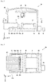
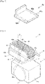
Fig. 5 is a perspective view showingdevice pallet 42. -
Fig. 6 is a perspective view showing an appearance ofAGV 10.Feeder movement device 16 illustrates onlycylinder section 16a, and the other configurations are not illustrated. Similar toFig. 6 ,feeder movement device 16 is partially illustrated inFigs. 7 ,9 ,11, 12 ,14 ,15, and 16 . -
Fig. 7 is a side view showing a configuration ofAGV 10. -
Fig. 8 is a view showing a state in whichcomponent supply feeder 40 anddevice pallet 42 are loaded on feeder installation table 52 ofstorage container 50. Other configurations than feeder installation table 52 ofstorage container 50 are not illustrated. -
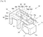
Fig. 9 is a view describing a measurement procedure for measuring height positions and inclination positions ofupper surfaces -
Fig. 10 is a flowchart showing a procedure for causingAGV 10 to delivercomponent supply feeder 40 tocomponent mounting machine 30. -
Fig. 11 is a view describing that the inclination and the height ofloading surface 13a ofAGV 10 are adjusted. -
Fig. 12 is a view describing thatcomponent supply feeder 40 is delivered from AGV 10 tocomponent mounting machine 30. -
Fig. 13 is a perspective view showing a modification example ofcomponent supply feeder 40. -
Fig. 14 is a view showing a state in whichcomponent supply feeder 140 is installed onloading surface 13a ofAGV 10. -
Fig. 15 is a view showing a state in whichcomponent supply feeder 140 is installed on feeder installation table 144. -
Fig. 16 is a view describing for measurement of the height position and the inclination position ofloading surface 13a ofAGV 10 with respect to the reference surface whencomponent supply feeder 140 of the modification example is used. - In one embodiment of the present technique, the movement device may move the member along the first loading surface and the second loading surface in a sliding manner when the height and the inclination of the first loading surface are adjusted in accordance with the height position and the inclination position of the second loading surface by the adjustment device. According to such a configuration, the member can be moved between the first loading surface and the second loading surface by merely sliding the member, and the configuration of the automatic conveyance apparatus (in particular, the movement device) can be simplified.
- In one embodiment of the present technique, the production system may include the automatic conveyance apparatus described above, a loading table provided with the second loading surface capable of loading the member, a production device configured to produce a specific object by using the member loaded on the loading table, a memory section configured to store reference position data including a reference height position and a reference inclination position of the second loading surface with respect to a reference surface set in advance, and a measurement section configured to measure a height position and an inclination position of the first loading surface with respect to the reference surface. The adjustment device may adjust the height and the inclination of the first loading surface based on the reference position data stored in the memory section and the height position and the inclination position of the first loading surface measured by the measurement section. According to such a configuration, since the reference height position and the reference inclination position of the loading table on the production device side are stored, by measuring the height position and the inclination position of the first loading surface on the automatic conveyance apparatus side, the height and the inclination of the first loading surface can be adjusted based on these data.
- In one embodiment of the present technique, the production system may include multiple loading tables provided with the second loading surface capable of loading the member. In this case, the memory section may store the reference position data of the second loading surface of the loading table for each of the multiple loading tables, and when the automatic conveyance apparatus is positioned at the member delivery position and/or the member pickup position of a specific loading table among the multiple loading tables, the adjustment device may adjust the height and the inclination of the first loading surface based on the reference position data of the specific loading table and the height position and the inclination position of the first loading surface measured by the measurement section. According to such a configuration, by storing the reference position data of the multiple loading tables, the height and the inclination of the first loading surface can be adjusted with respect to each of the loading tables.
- In one embodiment of the present technique, the loading table may be provided in the production device and/or a storage container for storing the members at least temporarily. The storage container herein may include a storage container having a buffer function in the factory by temporarily storing the member.
- In one embodiment of the present technique, the production device may be a component mounter configured to mount a component on a board, and the member may be a component supply feeder configured to supply the component to the component mounter. The specific configuration of the component supply feeder is not particularly limited and may be a tape type feeder that accommodates multiple components on a wound tape, a tray type feeder that accommodates multiple components on a tray, or a bulk type feeder that randomly accommodates multiple components in a container.
- Automated guided vehicle (AGV) 10 of the present exemplary embodiment and
production system 100 including the same will be described with reference to the drawings. As an example,production system 100 can be employed in a factory in whichcomponent mounting machine 30 is provided.Component mounting machine 30 mounts electronic component (hereinafter, referred to as component 4) 4 on a circuit board (hereinafter, referred to as board 2).Component mounting machine 10 is also referred to as an electronic component mounter or a chip mounter.Component mounting machine 10 is provided together with other board work machines such as a solder printing machine and a board inspection machine to constitute a series of mounting lines. - As shown in
Figs. 1 and2 ,production system 100 includesmanagement device 6, multiplecomponent mounting machines 30,multiple AGVs 10, andstorage container 50.Management device 6 is communicably connected to each ofcomponent mounting machines 30, each ofAGVs 10, andstorage container 50 in a bidirectional manner.Management device 6 controls operations of multiplecomponent mounting machines 30,multiple AGVs 10, andstorage container 50, and manages the entire mounting line.AGV 10 is an example of an automatic conveyance apparatus according to the technique disclosed in the present specification and conveyscomponent supply feeder 40 between multiplecomponent mounting machines 30 andstorage container 50. Further, inproduction system 100, multiple stop positions P1 to P5, which include multiple delivery positions/pickup positions for delivering and/or picking upcomponent supply feeder 40 to/from each ofcomponent mounting machines 30 andstorage container 50, are set.AGV 10 is configured to travel between multiple set stop positions (PI to P5) and delivers and/or picks upcomponent supply feeder 40 to/fromcomponent mounting machine 30 or storage container 50 (refer toFig. 1 ). Although multiplecomponent mounting machines 30 are arranged side by side in the x-direction, the number ofcomponent mounting machines 30 and the arrangement thereof to be arranged are not particularly limited. -
Component mounting machine 30 on whichcomponent supply feeder 40 is installed will be described with reference toFigs. 3 and 4 . As shown inFigs. 3 and 4 ,component mounting machine 30 includes multiplecomponent supply feeders 40,device pallet 42, feeder installation table 44, mountinghead 34,head movement device 36,board conveyor 38,touch panel 46, and mountingmachine control device 48. Each ofcomponent supply feeders 40 accommodatesmultiple components 4. As shown inFig. 5 ,device pallet 42 has a general plate shape and hasupper surface 42a andlower surface 42b positioned on the opposite side ofupper surface 42a.Upper surface 42a ofdevice pallet 42 can install multiplecomponent supply feeders 40 in an attachable and detachable manner.Device pallet 42 is attached onupper surface 44a of feeder installation table 44 in an attachable and detachable manner. By attachingdevice pallet 42 on whichcomponent supply feeder 40 is installed onupper surface 44a of feeder installation table 44,component supply feeder 40 is capable of supplyingcomponent 4 to mountinghead 34.Upper surface 44a of feeder installation table 44 is an example of a second loading surface according to the technique disclosed in the present specification. - Mounting
head 34 holds one ormultiple suction nozzles 32 in an attachable and detachable manner, picks upcomponent 4 supplied bycomponent supply feeder 40 by usingsuction nozzles 32, and mountscomponent 4 onboard 2. At this time,head movement device 36moves mounting head 34 with respect tocomponent supply feeder 40 andboard 2. As a result,component 4 is picked up from a specificcomponent supply feeder 40 among multiplecomponent supply feeders 40 so thatcomponent 4 is mounted on a position ofboard 2 set in advance.Board conveyor 38 loads, supports, and unloadsboard 2 along the x-direction.Touch panel 46 is a display device that provides an operator with various information ofcomponent mounting machine 30, as well as an input device that receives commands or information from the operator. Mountingmachine control device 48 is configured with a computer including a CPU and a storage device. Mountingmachine control device 48 is communicably connected tomanagement device 6. Mountingmachine control device 48 controls the operation of each section ofcomponent mounting machine 30 based on a production program transmitted frommanagement device 6. -
AGV 10 that conveyscomponent supply feeder 40 will be described with reference toFigs. 2 ,6 , and7 .AGV 10 picks up multiplecomponent supply feeders 40 before being used fromstorage container 50 and deliverscomponent supply feeder 40 before being used to component mounting machine 30 (that is, feeder installation table 44). Alternatively,AGV 10 picks upcomponent supply feeder 40 after being used from feeder installation table 44 ofcomponent mounting machine 30. As shown inFigs. 6 and7 ,AGV 10 includesvehicle body 11,wheels 17,adjustment device 14,feeder movement device 16,drive device 18, andcontrol device 12 that controls each section ofAGV 10.Vehicle body 11 includes vehicle bodymain body 11a that rotatably supportswheels 17, andpallet holding section 13 disposed on vehicle bodymain body 11a viaadjustment device 14.Pallet holding section 13 has a pair ofloading surfaces 13a arranged at intervals in the width direction ofvehicle body 11.Component supply feeder 40 is configured to be loadable on the pair ofloading surfaces 13a together withdevice pallet 42. That is, the pair ofloading surfaces 13a supports both ends 42c oflower surface 42b ofdevice pallet 42. Further,feeder movement device 16 is provided on each ofloading surfaces 13a. -
Feeder movement device 16 is a device that movescomponent supply feeder 40 from loadingsurface 13a, for example, toupper surface 44a of feeder installation table 44 ofcomponent mounting machine 30 and is driven bycontrol device 12. Specifically, the movement device movescomponent supply feeder 40 along the pair ofloading surfaces 13a andupper surface 44a of feeder installation table 44 in a sliding manner. Thefeeder movement device 16 has a pair ofcylinder sections 16a. Each of the pair ofcylinder sections 16a is provided with a piston mechanism. A catch mechanism (not shown) is provided atdistal end 16b of eachcylinder section 16a. The catch mechanism is configured to be capable of grippingend section 42d ofdevice pallet 42. By operating the piston mechanism in a state ofgripping device pallet 42,feeder movement device 16 can movedevice pallet 42, that is,component supply feeder 40 in the front-rear direction ofvehicle body 11. Afterdevice pallet 42 is moved to a predetermined position on the pair ofloading surfaces 13a or a predetermined position onupper surface 44a of feeder installation table 44, the gripping ofdevice pallet 42 byfeeder movement device 16 is released, so thatdevice pallet 42 is released fromfeeder movement device 16. As a result,AGV 10 can delivercomponent supply feeder 40 tocomponent mounting machine 30 orstorage container 50 or can pick upcomponent supply feeder 40 fromcomponent mounting machine 30 orstorage container 50. In the present exemplary embodiment,feeder movement device 16 moves component supply feeder 40 (more specifically, device pallet 42) betweenloading surface 13a andupper surface 44a of feeder installation table 44 in a sliding manner. Therefore,component supply feeder 40 can be moved with a small amount of power and the configuration ofAGV 10 can be simplified. -
Adjustment device 14 is a device, which is disposed between vehicle bodymain body 11a andpallet holding section 13 and adjusts the height and the inclination ofloading surface 13a ofpallet holding section 13, for example, in accordance with the height position and the inclination position ofupper surface 44a of feeder installation table 44 ofcomponent mounting machine 30, and is driven bycontrol device 12.Adjustment device 14 includes an actuator (not shown) and can adjust the position and the inclination (the inclination ofvehicle body 11 in the front-rear direction (θ inFig. 6 ) and the inclination in the left-right direction) of the pair ofloading surfaces 13a in the up-down direction.Adjustment device 14 includes a detection section that detects the drive amount of the actuator and can adjust the pair ofloading surfaces 13a to the desired height position and the desired inclination position by controlling the drive amount, which is detected by the detection section, to a target drive amount. Accordingly, the detection section that detects the drive amount of the actuator ofadjustment device 14 serves as a measurement section that measures the height and the inclination ofloading surface 13a. A well-known mechanism for adjusting the height and the inclination of the loading surface can be used asadjustment device 14. -
Drive device 18 is a device that driveswheels 17 to causeAGV 10 to travel and is driven bycontrol device 12.Drive device 18 is configured to be capable of independently driving left andright wheels 17, capable of causingAGV 10 to travel in the front-rear direction, and capable of freely adjusting the advancing direction ofAGV 10. Accordingly,AGV 10 can be stopped at any designated position and in any direction. -
Control device 12 controlsfeeder movement device 16,adjustment device 14, and drivedevice 18.Control device 12 is constituted by a computer including a CPU, a ROM, and a RAM.Control device 12 includescontrol section 12a andmemory section 12b, and various functions are assigned to controldevice 12 by executing a program installed in advance. As an example,control device 12 serves ascontrol section 12a that performs a process of drivingfeeder movement device 16 to movecomponent supply feeder 40 from loadingsurface 13a, a process of drivingadjustment device 14 to adjust the height and the inclination positions ofloading surface 13a, and a process of drivingdrive device 18 to causeAGV 10 to travel to any position.Control device 12 stores, for example, a command transmitted frommanagement device 6, and also serves asmemory section 12b that stores a map in the factory. The map referred to herein includes stop positions P1 to P4 set for eachcomponent mounting machine 30, and stop position P0 set forstorage container 50 or stop position P5 (also referred to as discharge position P5) for dischargingcomponent supply feeder 40 after being used to discharge place 54 (refer toFig. 1 ). -
AGV 10 includesinterface 20.AGV 10 is communicably (e.g., wirelessly) connected tomanagement device 6 in a bidirectional manner, and the command frommanagement device 6 can be received viainterface 20. -
Storage container 50 will be described with reference toFig. 8 .Storage container 50 stores multiplecomponent supply feeders 40 before being used incomponent mounting machine 30. As shown inFig. 8 ,storage container 50 includes feeder installation table 52.Device pallet 42 to which multiplecomponent supply feeders 40 are attached is configured to be loadable onupper surface 52a of feeder installation table 52.Storage container 50 is communicably connected tomanagement device 6. As an example,storage container 50 installsdevice pallet 42, to whichcomponent supply feeder 40 designated in response to the command frommanagement device 6 is attached, onupper surface 52a of feeder installation table 52. Further,storage container 50 reports an inventory status ofcomponent supply feeder 40 instorage container 50 tomanagement device 6. -
Management device 6 will be described with reference toFig. 2 .Management device 6 is communicably connected to each ofcomponent mounting machines 30, each of theAGVs 10, andstorage container 50, and manages all of these devices.Management device 6 is constituted by a computer including a CPU, a ROM, and a RAM. As shown inFig. 2 ,management device 6 includesmemory section 6a andcommand section 6b, and various functions are assigned tomanagement device 6 by executing the program installed in advance. As an example,management device 6 stores reference position data of each ofcomponent mounting machines 30 with respect to a reference surface set in advance and also serves asmemory section 6a that stores a production plan in the factory. The reference position data includes a reference height position and a reference inclination position with respect to the reference surface forupper surface 44a of feeder installation table 44 of eachcomponent mounting machine 30.Management device 6 serves ascommand section 6b that transmits the command for controlling eachcomponent mounting machine 30, eachAGV 10, andstorage container 50 based on the stored production plan, to each ofcomponent mounting machines 30,AGVs 10, andstorage container 50. - The floor surface of the factory in which
production system 100 described above is provided may be uneven. Therefore, the heights or the inclinations betweenupper surface 44a of feeder installation table 44 ofcomponent mounting machine 30 andloading surface 13a ofAGV 10 do not necessarily match each other. Therefore, it may be difficult to delivercomponent supply feeder 40 toupper surface 44a of feeder installation table 44 ofcomponent mounting machine 30 by simply movingcomponent supply feeder 40 from loadingsurface 13a in the front-rear direction in a sliding manner. The same can be applied when the member is picked up fromupper surface 44a of feeder installation table 44 toloading surface 13a ofAGV 10. - In the present exemplary embodiment,
AGV 10 includes, for example,adjustment device 14 that adjusts the height and the inclination ofloading surface 13a ofAGV 10 in accordance with the height position and the inclination position ofupper surface 44a of feeder installation table 44 ofcomponent mounting machine 30. Accordingly, inAGV 10, even when the floor surface of the factory is uneven, the height and the inclination ofloading surface 13a ofAGV 10 can be adjusted in accordance withupper surface 44a of feeder installation table 44 byadjustment device 14. As a result,AGV 10 can reliably move the member from loadingsurface 13a toupper surface 44a of feeder installation table 44 ofcomponent mounting machine 30 and/or fromupper surface 44a of feeder installation table 44 toloading surface 13a ofAGV 10.Upper surface 44a of feeder installation table 52 ofcomponent mounting machine 30 is an example of the second loading surface of the loading table in the technique disclosed in the present specification. The second loading surface of the loading table is not limited to this and may be, for example,upper surface 52a of feeder installation table 52 ofstorage container 50. - In
production system 100 of the present exemplary embodiment,management device 6 includesmeasurement section 6c and measurement device 60. By usingmeasurement section 6c and measurement device 60,AGV 10 performs advance preparation before the delivery and picking up ofdevice pallet 42. The advance preparation will be described with reference toFig. 9 . Measurement device 60 is a device used for measuring the height position and the inclination position ofloading surface 13a ofAGV 10 at each delivery/pickup position.Measurement section 6c ofmanagement device 6 calculates a target height position and a target inclination position ofloading surface 13a of eachAGV 10 with respect to a reference surface set in advance based on data measured by measurement device 60. As shown inFig. 9 , measurement device 60 includes a pair ofheight measurement devices 62 installed in the width direction ofvehicle body 11 and aninclination measurement device 64 installed in the center ofdevice pallet 42. As an example, theheight measurement device 62 can be constituted bylaser light projector 62a that emits laser andlaser light receiver 62b that receives the laser.Inclination measurement device 64 hassensor 64a that measures the inclination,transmitter 64b that transmits data measured bysensor 64a, and a receiver (not shown) that receives the data fromtransmitter 64b. However, the specific configuration or the measuring means of measurement device 60 is not limited to this, andloading surface 13a with respect to the reference surface may be measured by using other means. - Hereinafter, the measurement procedure will be described. The procedure for measuring the height position and the inclination position of
upper surface 44a of feeder installation table 44 andupper surface 52a of feeder installation table 52 with respect to the reference surface (in the present exemplary embodiment,loading surface 13a in an initial state ofAGV 10 positioned at each of stop positions P0 to P5) will be described as an example. Although not particularly limited, in the present exemplary embodiment, the operator performs a series of operations using measurement device 60. First,AGV 10 is positioned at stop position P0 ofstorage container 50. At this time,loading surface 13a ofAGV 10 is set in the initial state. Next,device pallet 42 is installed on each ofloading surface 13a ofAGV 10 andupper surface 52a of feeder installation table 52 ofstorage container 50. Afterdevice pallet 42 is installed, each ofinclination measurement device 64 andlaser light projector 62a is installed at a predetermined position onupper surface 42a ofdevice pallet 42 installed inAGV 10. Further,inclination measurement device 64 andlaser light receiver 62b are installed at predetermined positions ofdevice pallet 42 installed onupper surface 52a of feeder installation table 52. Next,adjustment device 14 ofAGV 10 is manually driven from the initial state, and the height position and the inclination ofdevice pallet 42 installed inAGV 10 are adjusted to match those ofdevice pallet 42 installed on feeder installation table 52. Specifically, the position is adjusted such that light oflaser light projector 62a can be received bylaser light receiver 62b, and also the twoinclination measurement devices 64 are adjusted so as to have the same value. When the adjustment of twodevice pallets 42 is ended, the drive amount (that is, the drive amount of the actuator) ofadjustment device 14 from the initial state is transmitted tomanagement device 6.Measurement section 6c ofmanagement device 6 calculates the height position and the inclination position ofupper surface 52a of feeder installation table 52 with respect to the reference surface at stop position P0 based on the received drive amount ofadjustment device 14. The calculated height position and the inclination position ofupper surface 52a of feeder installation table 52 are stored inmemory section 6a. The above-described measurement is performed for each of stop positions P1 to P5. As a result, the height positions and the inclination positions ofupper surface 44a of feeder installation table 44 andupper surface 52a of feeder installation table 52 at each of stop positions P0 to P5 are measured, and the measured positions are stored inmemory section 6a.Management device 6 may transmit the height positions and the inclination positions ofupper surface 44a of feeder installation table 44 andupper surface 52a of feeder installation table 52 at each of stop positions P0 to P5 toAGV 10. - In
production system 100 of the present exemplary embodiment,AGV 10 stores the height positions and the inclination positions ofupper surface 44a of feeder installation table 44 andupper surface 52a of feeder installation table 52 at each of stop positions P0 to P5 and adjusts the drive amount ofadjustment device 14 in accordance with the stored height positions and inclination positions. As a result, the height and the inclination ofloading surface 13a ofAGV 10 can be adjusted in accordance withupper surface 44a of feeder installation table 44 andupper surface 52a of feeder installation table 52. Therefore, in various usage environments (in which conditions of traveling surfaces are different), the automatic exchange ofcomponent supply feeder 40 can be suitably performed. - A procedure for
AGV 10 to delivercomponent supply feeder 40 will be described with reference toFigs. 10 to 12 .Management device 6 manages the production status of eachcomponent mounting machine 30 and can determine whether exchange ofcomponent supply feeder 40 is necessary for each ofcomponent mounting machines 30. When it is determined that the exchange ofcomponent supply feeder 40 is necessary for a specific component mounting machine 30 (for example, the component mountingmachine # 4 inFig. 1 ),management device 6controls storage container 50 to preparedevice pallet 42, on whichcomponent supply feeder 40 before being used is installed, on feeder installation table 52. Instorage container 50, the designatedcomponent supply feeder 40 on feeder installation table 52 is set.Management device 6 controls the selected oneAGV 10 to delivercomponent supply feeder 40 to component mounting machine 30 (# 4).Management device 6 may controlAGV 10, which is on standby in the vicinity ofstorage container 50 amongmultiple AGVs 10, to operate based on the stored map in the factory and the positional information of each ofAGVs 10. - In step S12,
AGV 10 receives, frommanagement device 6, the command to delivercomponent supply feeder 40 to specific component mounting machine 30 (for example, the component mountingmachine # 4 inFig. 1 ). At this time,control device 12 stores the command frommanagement device 6. Specifically,AGV 10 receives, frommanagement device 6, an identification number (#4) ofcomponent mounting machine 30, reference position data of component mounting machine 30 (the drive amount of adjustment device 14), and reference position data of storage container 50 (the drive amount of adjustment device 14), and stores the received identification number and reference position data. - In step S14,
AGV 10 makes a move to pickup position P0 ofstorage container 50. Specifically, whenAGV 10 receives the command frommanagement device 6,AGV 10 drives drivedevice 18 to moveAGV 10 to pickup position P0 ofstorage container 50 based on the map of the factory stored incontrol device 12. WhenAGV 10 is positioned at pickup position P0, the process proceeds to the next step S16. - As shown in
Fig. 11 , in step S16,AGV 10 controls the drive amount ofadjustment device 14 to adjust the inclination and the height ofloading surface 13a ofAGV 10 based on the reference position data (the drive amount of adjustment device 14) at pickup position P0 ofstorage container 50. When the adjustment ofloading surface 13a is completed, the process proceeds to the next step S18. - In step S18,
AGV 10 picks upcomponent supply feeder 40 fromupper surface 52a of feeder installation table 52 ofstorage container 50 toloading surface 13a. Specifically,control device 12 drivesfeeder movement device 16 to move the pair ofcylinder sections 16a offeeder movement device 16 towarddevice pallet 42 on feeder installation table 52. When distal ends 16b of the pair ofcylinder sections 16a are in contact withdevice pallet 42,feeder movement device 16 grips endsections 42d ofdevice pallet 42 by using the catch mechanism and movesdevice pallet 42 in the front-rear direction in a sliding manner to pull outdevice pallet 42. Whendevice pallet 42 is positioned at a predetermined loading position onloading surface 13a ofAGV 10, the process proceeds to the next step S20. Afterdevice pallet 42 is positioned at the loading position,loading surface 13a also returns to the initial state position. - In step S20,
AGV 10 makes a move to delivery position P4 of designated component mounting machine 30 (#4). Specifically,AGV 10 drives drivedevice 18 to make a move to delivery position P4 of designated component mounting machine 30 (#4) based on the map of the factory stored incontrol device 12. WhenAGV 10 is positioned at delivery position P4, the process proceeds to the next step S22. - In step S22, the drive amount of
adjustment device 14 is controlled to adjust the inclination and the height ofloading surface 13a ofAGV 10 based on the reference position data at delivery position P4 of designated component mounting machine 30 (#4). When the adjustment ofloading surface 13a is completed, the process proceeds to the next step S24. - As shown in
Fig. 12 , in step S24,AGV 10 deliverscomponent supply feeder 40 from loadingsurface 13a toupper surface 52a of feeder installation table 52 ofcomponent mounting machine 30. Specifically,control device 12 drivesfeeder movement device 16, and the pair ofcylinder sections 16a offeeder movement device 16moves device pallet 42 in a direction of pushingdevice pallet 42 out to feeder installation table 44 while gripping thedevice pallet 42. Whendevice pallet 42 is positioned at the installation position, the state in which distal ends 16b of the pair ofcylinder sections 16agrip end sections 42d ofdevice pallet 42 is released.Control device 12 drivesfeeder movement device 16 to move thecylinder section 16a to an original position onloading surface 13a. Whencylinder section 16a is positioned onloading surface 13a,loading surface 13a also returns to the initial state position. - As a result of the above steps, the procedure for delivering
component supply feeder 40 ofAGV 10 is completed. Whenmanagement device 6 determines that it is necessary to exchangecomponent supply feeder 40 in a specific component mounting machine 30 (for example, the component mounting machine #2), and it is necessary to pick upcomponent supply feeder 40 after being used from the specificcomponent mounting machine 30,management device 6controls AGV 10 to pick upcomponent supply feeder 40 after being used from specificcomponent mounting machine 30. Hereinafter, the procedure for picking up will be described. -
AGV 10 receives a command to pick upcomponent supply feeder 40 frommanagement device 6. At this time,control device 12 stores the command frommanagement device 6. Specifically,AGV 10 receives, frommanagement device 6, an identification number (# 2) ofcomponent mounting machine 30, reference position data ofcomponent mounting machine 30, and reference position data at stop position P5 ofdischarge place 54, and stores the received identification number and reference position data. - Next,
AGV 10 makes a move to pickup position P2 of component mounting machine 30 (# 2). WhenAGV 10 is positioned at pickup position P2,AGV 10 drivesadjustment device 14 to adjust the inclination and the height ofloading surface 13a ofAGV 10 based on the reference position data at pickup position P2 of component mounting machine 30 (# 2). Next,AGV 10 drivesfeeder movement device 16 to pick upcomponent supply feeder 40 fromupper surface 44a of feeder installation table 44 of component mounting machine 30 (# 2) toloading surface 13a. - The procedure for picking up
component supply feeder 40 is completed as described above. AfterAGV 10 picks upcomponent supply feeder 40 after being used,AGV 10 makes a move to discharge position P5 ofdischarge place 54 and dischargescomponent supply feeder 40 after being used to dischargeplace 54. The operation atdischarge place 54 is performed in the same manner as the operation of deliveringcomponent supply feeder 40 tocomponent mounting machine 30. - Another embodiment of
production system 100 includingAGV 10 of the present exemplary embodiment will be described with reference toFigs. 13 to 16 . In the above exemplary embodiment,component supply feeder 40 employs a tape type feeder that accommodatesmultiple components 4 on a wound tape, but the shape or type ofcomponent supply feeder 40 is not particularly limited and may be variously changed in other manners. Further, the configuration of each section ofproduction system 100 can be appropriately changed in accordance withcomponent supply feeder 40. For example, as shown inFig. 13 ,component supply feeder 140 may be a tray type feeder in whichmultiple components 4 are accommodated ontray 141. Multiplecomponent supply feeders 140 are accommodated intray magazine 142. Multiple component supply feeders 140 (more specifically, tray magazines 142) are installed on the pair ofloading surfaces 13a in an attachable and detachable manner. Accordingly,device pallet 42 used in the above exemplary embodiment is not required in multiplecomponent supply feeders 140. Further, the position or the shape of feeder installation table 144 ofcomponent mounting machine 30 may be different in accordance with this. Hereinafter, feeder installation table 144 to be changed will be described. Other configurations of the modification example ofproduction system 100 are the same as those of the exemplary embodiment, and duplicate descriptions thereof will be omitted. - As shown in
Fig. 14, feeder installation table 144 ofcomponent mounting machine 30 may be provided separately fromcomponent mounting machine 30 at a position adjacent tocomponent mounting machine 30.Upper surface 144a of feeder installation table 144 is configured to be capable of loadingcomponent supply feeder 140. In this case,component supply feeder 140 is loaded onupper surface 144a of feeder installation table 144 whencomponent supply feeder 140 is delivered fromAGV 10 tocomponent mounting machine 30. - Further, as shown in
Figs. 14 and15 ,feeder movement device 16 may also be configured to gripframe section 142a oftray magazine 142 by using the catch mechanism atdistal end 16b of eachcylinder section 16a. After grippingframe section 142a,feeder movement device 16 may move component supply feeder 140 (specifically, tray magazine 142) by using the piston mechanism. As a result, even with suchcomponent supply feeder 140,AGV 10 can reliably movecomponent supply feeder 140 from loadingsurface 13a toupper surface 144a of feeder installation table 144 ofcomponent mounting machine 30 and/or fromupper surface 144a of feeder installation table 144 toloading surface 13a ofAGV 10. - In
component supply feeder 140, the advance preparation is also partially different from the exemplary embodiment. As shown inFig. 16 , measurement device 60 may include twomeasurement pallets 143. Sincedevice pallet 42 is not used, twomeasurement pallets 143 may be used when measuring the height positions and the inclination positions ofupper surfaces upper surface 52a of feeder installation table 52 ofstorage container 50, eachmeasurement pallet 143 may be installed on each ofloading surface 13a ofAGV 10 andupper surface 52a of feeder installation table 52 ofstorage container 50. Further, onupper surface 143a of eachmeasurement pallet 143, measurement device 60 is installed at each predetermined position so that the operator can perform measurement in the same procedure as in the exemplary embodiment. - The number of
storage containers 50 included inproduction system 100 of the present exemplary embodiment is not particularly limited.Production system 100 may includemultiple storage containers 50. In this case,multiple storage containers 50 may include a storage container having a buffer function in the mounting line by temporarily storingcomponent supply feeder 40. - In
production system 100 of the present exemplary embodiment,AGV 10 includesadjustment device 14,feeder movement device 16, andcontrol device 12, but these devices may be provided outside AGV 10 (for example, oncomponent mounting machine 30 side). As a result, for example, even when the floor surface of the factory is not flat,AGV 10 can reliably movecomponent supply feeder 40 from loadingsurface 13a to, for example,upper surface 44a of feeder installation table 44 ofcomponent mounting machine 30 and/or fromupper surface 44a of feeder installation table 44 ofcomponent mounting machine 30 toloading surface 13a. - Although specific examples of the technique disclosed in the present specification have been described in detail, these are mere examples and do not limit the scope of the claims. The technique described in the scope of the claims includes various modifications and variations of the specific examples illustrated above. Technical elements described in the present specification or the drawings exhibit technical usefulness alone or in various combinations, and are not limited to combinations described in claims at the time of filing. The techniques illustrated in the present specification or the drawings can achieve multiple objects simultaneously and provide technical usefulness by achieving one object in the multiple objects.
-
- 2: board
- 4: component
- 6: management device
- 6a: memory section
- 6b: command section
- 6c: measurement section
- 10: component mounting machine
- 11: vehicle body
- 12: control device
- 12a: control section
- 12b: memory section
- 13: pallet holding section
- 13a: loading surface
- 14: adjustment device
- 16: feeder movement device
- 17: wheel
- 18: drive device
- 20: interface
- 30: component mounting machine
- 40, 140: component supply feeder
- 42: device pallet
- 42a: upper surface
- 44, 144: feeder installation table
- 44a, 144a: upper surface
- 48: mounting machine control device
- 50: storage container
- 52: feeder installation table
- 52a: upper surface
- 60: measurement device
- 62: height measurement device
- 64: inclination measurement device
- 64a: sensor
- 64b: transmitter
- 100: production system
- 141: tray
- 142: tray magazine
- 142a: frame section
Claims (7)
- An automatic conveyance apparatus, whichis employed together with a loading table for loading a member supplied from outside and a production device for producing a specific object by using the member loaded on the loading table,delivers the member before being used on the loading table, andpicks up the member after being used from the loading table, the automatic conveyance apparatus comprising:a first loading surface capable of loading the member;an adjustment device configured to adjust a height and an inclination of the first loading surface in accordance with a height position and an inclination position of a second loading surface provided on the loading table on which the member is loaded;a movement device configured to move the member from the first loading surface to the second loading surface and/or from the second loading surface to the first loading surface; anda control section configured to drive the movement device to move the member between the first loading surface and the second loading surface when the automatic conveyance apparatus is positioned at a member delivery position and/or a member pickup position where the automatic conveyance apparatus delivers and/or picks up the member, and when the height and the inclination of the first loading surface are adjusted in accordance with the height position and the inclination position of the second loading surface by the adjustment device,wherein the automatic conveyance apparatus is configured to travel between multiple predetermined positions including the member delivery position and/or the member pickup position.
- The automatic conveyance apparatus according to claim 1,
wherein the movement device moves the member along the first loading surface and the second loading surface in a sliding manner when the height and the inclination of the first loading surface are adjusted in accordance with the height position and the inclination position of the second loading surface by the adjustment device. - A production system comprising:the automatic conveyance apparatus according to claim 1 or 2;a loading table provided with the second loading surface capable of loading the member;a production device configured to produce a specific object by using the member loaded on the loading table;a memory section configured to store reference position data including a reference height position and a reference inclination position of the second loading surface with respect to a reference surface set in advance; anda measurement section configured to measure a height position and an inclination position of the first loading surface with respect to the reference surface,wherein the adjustment device adjusts a height and an inclination of the first loading surface based on the reference position data stored in the memory section and the height position and the inclination position of the first loading surface measured by the measurement section.
- The production system according to claim 3,wherein the production system includes multiple loading tables provided with the second loading surface capable of loading the member,the memory section stores the reference position data of the second loading surface of the loading table for each of the multiple loading tables, andwhen the automatic conveyance apparatus is positioned at the member delivery position and/or the member pickup position of a specific loading table among the multiple loading tables, the adjustment device adjusts the height and the inclination of the first loading surface based on the reference position data of the specific loading table and the height position and the inclination position of the first loading surface measured by the measurement section.
- The production system according to claim 3 or 4,
wherein the loading table is provided in the production device and/or a storage container for storing the members at least temporarily. - The production system according to any one of claims 3 to 5,wherein the production device is a component mounter configured to mount a component on a board, andthe member is a component supply feeder configured to supply the component to the component mounter.
- A production system comprising:a loading table capable of loading a member supplied from outside;a production device configured to produce a specific object by using the member loaded on the loading table; andan automatic conveyance apparatus configured to deliver the member before being used and/or after being used on the loading table and pick up the member before being used and/or after being used,wherein the automatic conveyance apparatus includes a first loading surface capable of loading the member and is configured to travel between multiple predetermined positions including a member delivery position and/or a member pickup position,the loading table includes a second loading surface capable of loading the member, andthe production system further comprises:an adjustment device configured to adjust a height and an inclination of the first loading surface in accordance with a height position and an inclination position of the second loading surface;a movement device configured to move the member from the first loading surface to the second loading surface and/or from the second loading surface to the first loading surface; anda control section configured to drive the movement device to move the member between the first loading surface and the second loading surface when the automatic conveyance apparatus is positioned at the member delivery position and/or the member pickup position, and when the height and the inclination of the first loading surface are adjusted in accordance with the height position and the inclination position of the second loading surface by the adjustment device.
Applications Claiming Priority (1)
| Application Number | Priority Date | Filing Date | Title |
|---|---|---|---|
| PCT/JP2019/030166 WO2021019755A1 (en) | 2019-08-01 | 2019-08-01 | Automatic conveyance apparatus and production system comprising same |
Publications (3)
| Publication Number | Publication Date |
|---|---|
| EP4009758A1 true EP4009758A1 (en) | 2022-06-08 |
| EP4009758A4 EP4009758A4 (en) | 2022-07-27 |
| EP4009758B1 EP4009758B1 (en) | 2024-07-31 |
Family
ID=74228638
Family Applications (1)
| Application Number | Title | Priority Date | Filing Date |
|---|---|---|---|
| EP19939175.6A Active EP4009758B1 (en) | 2019-08-01 | 2019-08-01 | Automatic conveyance apparatus and production system comprising same |
Country Status (5)
| Country | Link |
|---|---|
| US (1) | US11792968B2 (en) |
| EP (1) | EP4009758B1 (en) |
| JP (1) | JP7106765B2 (en) |
| CN (1) | CN114208410B (en) |
| WO (1) | WO2021019755A1 (en) |
Cited By (2)
| Publication number | Priority date | Publication date | Assignee | Title |
|---|---|---|---|---|
| WO2023248021A1 (en) * | 2022-06-21 | 2023-12-28 | ASMPT GmbH & Co. KG | Transport vehicle having a rotatable and vertically movable exchanging device for component part feed devices |
| WO2025186646A1 (en) * | 2024-03-05 | 2025-09-12 | Asmpt Smt Singapore Pte. Ltd. | Smt material transfer |
Families Citing this family (3)
| Publication number | Priority date | Publication date | Assignee | Title |
|---|---|---|---|---|
| JP7570048B2 (en) * | 2021-03-15 | 2024-10-21 | パナソニックIpマネジメント株式会社 | Pallet storage device and tray parts management system |
| DE102021117281B9 (en) * | 2021-07-05 | 2023-02-23 | Asm Assembly Systems Gmbh & Co. Kg | Automatic replacement of a component feed device using a driverless transport vehicle in conjunction with a finely positionable positioning device |
| WO2025109650A1 (en) * | 2023-11-20 | 2025-05-30 | ヤマハ発動機株式会社 | Work device, device on which to perform work, work system, and method for adjusting position of work unit relative to device on which to perform work |
Family Cites Families (19)
| Publication number | Priority date | Publication date | Assignee | Title |
|---|---|---|---|---|
| JPH03124700A (en) * | 1989-10-06 | 1991-05-28 | Toyota Autom Loom Works Ltd | Cargo work control device of unmanned form lift |
| JPH066084A (en) * | 1992-06-19 | 1994-01-14 | Olympus Optical Co Ltd | Automatic electronic part installation equipment |
| JP3307024B2 (en) * | 1993-11-02 | 2002-07-24 | 松下電器産業株式会社 | Parts feeder supply device |
| WO2001026440A1 (en) * | 1999-05-21 | 2001-04-12 | Matsushita Electric Industrial Co., Ltd. | Device for transferring/holding sheetlike member and its method |
| JP4322092B2 (en) * | 2002-11-13 | 2009-08-26 | 富士機械製造株式会社 | Calibration method and apparatus for electronic component mounting apparatus |
| CN1662132B (en) * | 2004-02-26 | 2010-08-18 | 欧姆龙株式会社 | Mounting error detection method and substrate detection device using the method |
| JP4666216B2 (en) * | 2005-08-11 | 2011-04-06 | 株式会社ダイフク | Goods storage equipment |
| JPWO2010143466A1 (en) * | 2009-06-12 | 2012-11-22 | コニカミノルタアドバンストレイヤー株式会社 | Wafer lens manufacturing method, intermediate mold, optical component, mold and mold manufacturing method |
| JP5615081B2 (en) * | 2010-07-26 | 2014-10-29 | 富士機械製造株式会社 | Component mounting equipment |
| EP2914077B1 (en) * | 2012-10-29 | 2021-04-07 | FUJI Corporation | Component supply apparatus |
| JP2015044659A (en) * | 2013-08-28 | 2015-03-12 | 平和製罐株式会社 | Target board loading device and conveyance system |
| JP6288997B2 (en) * | 2013-09-17 | 2018-03-07 | セーレン株式会社 | Inkjet recording device |
| JP6462530B2 (en) * | 2015-08-25 | 2019-01-30 | ヤマハ発動機株式会社 | Exchange cart and surface mounter |
| JP6561317B2 (en) * | 2016-06-01 | 2019-08-21 | パナソニックIpマネジメント株式会社 | Component mounting system |
| WO2018109793A1 (en) * | 2016-12-12 | 2018-06-21 | 株式会社Fuji | Tape feeder set-up system |
| JP6751445B2 (en) | 2017-01-06 | 2020-09-02 | 株式会社Fuji | Automatic feeder replacement system for component mounting line |
| US10289117B1 (en) | 2017-02-21 | 2019-05-14 | Amazon Technologies, Inc. | Lift and tilt platform |
| CN110431928B (en) | 2017-03-23 | 2021-06-01 | 株式会社富士 | Installation system and display control device |
| CN207077181U (en) * | 2017-06-03 | 2018-03-09 | 广东星徽精密制造股份有限公司 | A kind of outer rail annex automatic assembling machine |
-
2019
- 2019-08-01 JP JP2021536568A patent/JP7106765B2/en active Active
- 2019-08-01 EP EP19939175.6A patent/EP4009758B1/en active Active
- 2019-08-01 US US17/631,815 patent/US11792968B2/en active Active
- 2019-08-01 CN CN201980098766.9A patent/CN114208410B/en active Active
- 2019-08-01 WO PCT/JP2019/030166 patent/WO2021019755A1/en not_active Ceased
Cited By (2)
| Publication number | Priority date | Publication date | Assignee | Title |
|---|---|---|---|---|
| WO2023248021A1 (en) * | 2022-06-21 | 2023-12-28 | ASMPT GmbH & Co. KG | Transport vehicle having a rotatable and vertically movable exchanging device for component part feed devices |
| WO2025186646A1 (en) * | 2024-03-05 | 2025-09-12 | Asmpt Smt Singapore Pte. Ltd. | Smt material transfer |
Also Published As
| Publication number | Publication date |
|---|---|
| CN114208410B (en) | 2023-10-13 |
| EP4009758A4 (en) | 2022-07-27 |
| US20220279690A1 (en) | 2022-09-01 |
| JP7106765B2 (en) | 2022-07-26 |
| US11792968B2 (en) | 2023-10-17 |
| JPWO2021019755A1 (en) | 2021-02-04 |
| WO2021019755A1 (en) | 2021-02-04 |
| EP4009758B1 (en) | 2024-07-31 |
| CN114208410A (en) | 2022-03-18 |
Similar Documents
| Publication | Publication Date | Title |
|---|---|---|
| EP4009758B1 (en) | Automatic conveyance apparatus and production system comprising same | |
| CN112042285B (en) | Automatic replacement system, management device, and automatic replacement method | |
| KR100389755B1 (en) | Equipment and method for mounting electronic components | |
| CN109982852B (en) | Printing equipment and printing systems | |
| WO2018008148A1 (en) | Component-mounting system and management device | |
| EP3579676B1 (en) | Coordinate data generation device and coordinate data generation method | |
| EP3764763B1 (en) | Component mounting system | |
| JP2023009011A (en) | Automatic replacement of assembly component feeding device using unmanned transportation vehicle interlocked with positioning device capable of accurate positioning | |
| US12022620B2 (en) | Tray parts feeder | |
| JP2010087451A (en) | Electronic component mounting device, and control method for tape feeder of electronic component mounting device | |
| US12108538B2 (en) | Component type management device | |
| CN101945568B (en) | Electronic compound mounting device | |
| US11997797B2 (en) | Setup change task setting device | |
| EP3125665B1 (en) | Component mounting device | |
| US20250296782A1 (en) | Article conveyance system and article conveyance method | |
| US12615751B2 (en) | Device management apparatus, substrate work machine, and device management method | |
| JP7464753B2 (en) | Production System | |
| WO2015011779A1 (en) | Work machine | |
| EP3684157B1 (en) | Mounting system | |
| CN120530724A (en) | Production guidance device and production guidance method | |
| JP2002359493A (en) | Electronic component mounting device | |
| WO2023047464A1 (en) | Work device and mounting system |
Legal Events
| Date | Code | Title | Description |
|---|---|---|---|
| STAA | Information on the status of an ep patent application or granted ep patent |
Free format text: STATUS: THE INTERNATIONAL PUBLICATION HAS BEEN MADE |
|
| PUAI | Public reference made under article 153(3) epc to a published international application that has entered the european phase |
Free format text: ORIGINAL CODE: 0009012 |
|
| STAA | Information on the status of an ep patent application or granted ep patent |
Free format text: STATUS: REQUEST FOR EXAMINATION WAS MADE |
|
| 17P | Request for examination filed |
Effective date: 20220112 |
|
| AK | Designated contracting states |
Kind code of ref document: A1 Designated state(s): AL AT BE BG CH CY CZ DE DK EE ES FI FR GB GR HR HU IE IS IT LI LT LU LV MC MK MT NL NO PL PT RO RS SE SI SK SM TR |
|
| A4 | Supplementary search report drawn up and despatched |
Effective date: 20220627 |
|
| RIC1 | Information provided on ipc code assigned before grant |
Ipc: B65G 1/04 20060101ALI20220622BHEP Ipc: H05K 13/00 20060101ALI20220622BHEP Ipc: H05K 13/02 20060101AFI20220622BHEP |
|
| DAV | Request for validation of the european patent (deleted) | ||
| DAX | Request for extension of the european patent (deleted) | ||
| P01 | Opt-out of the competence of the unified patent court (upc) registered |
Effective date: 20230328 |
|
| GRAP | Despatch of communication of intention to grant a patent |
Free format text: ORIGINAL CODE: EPIDOSNIGR1 |
|
| STAA | Information on the status of an ep patent application or granted ep patent |
Free format text: STATUS: GRANT OF PATENT IS INTENDED |
|
| INTG | Intention to grant announced |
Effective date: 20240425 |
|
| GRAS | Grant fee paid |
Free format text: ORIGINAL CODE: EPIDOSNIGR3 |
|
| GRAA | (expected) grant |
Free format text: ORIGINAL CODE: 0009210 |
|
| STAA | Information on the status of an ep patent application or granted ep patent |
Free format text: STATUS: THE PATENT HAS BEEN GRANTED |
|
| AK | Designated contracting states |
Kind code of ref document: B1 Designated state(s): AL AT BE BG CH CY CZ DE DK EE ES FI FR GB GR HR HU IE IS IT LI LT LU LV MC MK MT NL NO PL PT RO RS SE SI SK SM TR |
|
| REG | Reference to a national code |
Ref country code: CH Ref legal event code: EP Ref country code: GB Ref legal event code: FG4D |
|
| REG | Reference to a national code |
Ref country code: DE Ref legal event code: R096 Ref document number: 602019056388 Country of ref document: DE |
|
| REG | Reference to a national code |
Ref country code: NL Ref legal event code: FP Ref country code: IE Ref legal event code: FG4D |
|
| REG | Reference to a national code |
Ref country code: LT Ref legal event code: MG9D |
|
| PG25 | Lapsed in a contracting state [announced via postgrant information from national office to epo] |
Ref country code: PT Free format text: LAPSE BECAUSE OF FAILURE TO SUBMIT A TRANSLATION OF THE DESCRIPTION OR TO PAY THE FEE WITHIN THE PRESCRIBED TIME-LIMIT Effective date: 20241202 |
|
| REG | Reference to a national code |
Ref country code: AT Ref legal event code: MK05 Ref document number: 1709819 Country of ref document: AT Kind code of ref document: T Effective date: 20240731 |
|
| PG25 | Lapsed in a contracting state [announced via postgrant information from national office to epo] |
Ref country code: PT Free format text: LAPSE BECAUSE OF FAILURE TO SUBMIT A TRANSLATION OF THE DESCRIPTION OR TO PAY THE FEE WITHIN THE PRESCRIBED TIME-LIMIT Effective date: 20241202 |
|
| PG25 | Lapsed in a contracting state [announced via postgrant information from national office to epo] |
Ref country code: NO Free format text: LAPSE BECAUSE OF FAILURE TO SUBMIT A TRANSLATION OF THE DESCRIPTION OR TO PAY THE FEE WITHIN THE PRESCRIBED TIME-LIMIT Effective date: 20241031 |
|
| PG25 | Lapsed in a contracting state [announced via postgrant information from national office to epo] |
Ref country code: FI Free format text: LAPSE BECAUSE OF FAILURE TO SUBMIT A TRANSLATION OF THE DESCRIPTION OR TO PAY THE FEE WITHIN THE PRESCRIBED TIME-LIMIT Effective date: 20240731 Ref country code: GR Free format text: LAPSE BECAUSE OF FAILURE TO SUBMIT A TRANSLATION OF THE DESCRIPTION OR TO PAY THE FEE WITHIN THE PRESCRIBED TIME-LIMIT Effective date: 20241101 Ref country code: PL Free format text: LAPSE BECAUSE OF FAILURE TO SUBMIT A TRANSLATION OF THE DESCRIPTION OR TO PAY THE FEE WITHIN THE PRESCRIBED TIME-LIMIT Effective date: 20240731 |
|
| PG25 | Lapsed in a contracting state [announced via postgrant information from national office to epo] |
Ref country code: BG Free format text: LAPSE BECAUSE OF FAILURE TO SUBMIT A TRANSLATION OF THE DESCRIPTION OR TO PAY THE FEE WITHIN THE PRESCRIBED TIME-LIMIT Effective date: 20240731 |
|
| PG25 | Lapsed in a contracting state [announced via postgrant information from national office to epo] |
Ref country code: LV Free format text: LAPSE BECAUSE OF FAILURE TO SUBMIT A TRANSLATION OF THE DESCRIPTION OR TO PAY THE FEE WITHIN THE PRESCRIBED TIME-LIMIT Effective date: 20240731 |
|
| PG25 | Lapsed in a contracting state [announced via postgrant information from national office to epo] |
Ref country code: IS Free format text: LAPSE BECAUSE OF FAILURE TO SUBMIT A TRANSLATION OF THE DESCRIPTION OR TO PAY THE FEE WITHIN THE PRESCRIBED TIME-LIMIT Effective date: 20241130 Ref country code: AT Free format text: LAPSE BECAUSE OF FAILURE TO SUBMIT A TRANSLATION OF THE DESCRIPTION OR TO PAY THE FEE WITHIN THE PRESCRIBED TIME-LIMIT Effective date: 20240731 |
|
| PG25 | Lapsed in a contracting state [announced via postgrant information from national office to epo] |
Ref country code: HR Free format text: LAPSE BECAUSE OF FAILURE TO SUBMIT A TRANSLATION OF THE DESCRIPTION OR TO PAY THE FEE WITHIN THE PRESCRIBED TIME-LIMIT Effective date: 20240731 |
|
| PG25 | Lapsed in a contracting state [announced via postgrant information from national office to epo] |
Ref country code: ES Free format text: LAPSE BECAUSE OF FAILURE TO SUBMIT A TRANSLATION OF THE DESCRIPTION OR TO PAY THE FEE WITHIN THE PRESCRIBED TIME-LIMIT Effective date: 20240731 Ref country code: RS Free format text: LAPSE BECAUSE OF FAILURE TO SUBMIT A TRANSLATION OF THE DESCRIPTION OR TO PAY THE FEE WITHIN THE PRESCRIBED TIME-LIMIT Effective date: 20241031 |
|
| PG25 | Lapsed in a contracting state [announced via postgrant information from national office to epo] |
Ref country code: RS Free format text: LAPSE BECAUSE OF FAILURE TO SUBMIT A TRANSLATION OF THE DESCRIPTION OR TO PAY THE FEE WITHIN THE PRESCRIBED TIME-LIMIT Effective date: 20241031 Ref country code: PL Free format text: LAPSE BECAUSE OF FAILURE TO SUBMIT A TRANSLATION OF THE DESCRIPTION OR TO PAY THE FEE WITHIN THE PRESCRIBED TIME-LIMIT Effective date: 20240731 Ref country code: NO Free format text: LAPSE BECAUSE OF FAILURE TO SUBMIT A TRANSLATION OF THE DESCRIPTION OR TO PAY THE FEE WITHIN THE PRESCRIBED TIME-LIMIT Effective date: 20241031 Ref country code: LV Free format text: LAPSE BECAUSE OF FAILURE TO SUBMIT A TRANSLATION OF THE DESCRIPTION OR TO PAY THE FEE WITHIN THE PRESCRIBED TIME-LIMIT Effective date: 20240731 Ref country code: IS Free format text: LAPSE BECAUSE OF FAILURE TO SUBMIT A TRANSLATION OF THE DESCRIPTION OR TO PAY THE FEE WITHIN THE PRESCRIBED TIME-LIMIT Effective date: 20241130 Ref country code: HR Free format text: LAPSE BECAUSE OF FAILURE TO SUBMIT A TRANSLATION OF THE DESCRIPTION OR TO PAY THE FEE WITHIN THE PRESCRIBED TIME-LIMIT Effective date: 20240731 Ref country code: GR Free format text: LAPSE BECAUSE OF FAILURE TO SUBMIT A TRANSLATION OF THE DESCRIPTION OR TO PAY THE FEE WITHIN THE PRESCRIBED TIME-LIMIT Effective date: 20241101 Ref country code: FI Free format text: LAPSE BECAUSE OF FAILURE TO SUBMIT A TRANSLATION OF THE DESCRIPTION OR TO PAY THE FEE WITHIN THE PRESCRIBED TIME-LIMIT Effective date: 20240731 Ref country code: ES Free format text: LAPSE BECAUSE OF FAILURE TO SUBMIT A TRANSLATION OF THE DESCRIPTION OR TO PAY THE FEE WITHIN THE PRESCRIBED TIME-LIMIT Effective date: 20240731 Ref country code: BG Free format text: LAPSE BECAUSE OF FAILURE TO SUBMIT A TRANSLATION OF THE DESCRIPTION OR TO PAY THE FEE WITHIN THE PRESCRIBED TIME-LIMIT Effective date: 20240731 Ref country code: AT Free format text: LAPSE BECAUSE OF FAILURE TO SUBMIT A TRANSLATION OF THE DESCRIPTION OR TO PAY THE FEE WITHIN THE PRESCRIBED TIME-LIMIT Effective date: 20240731 |
|
| REG | Reference to a national code |
Ref country code: CH Ref legal event code: PL |
|
| PG25 | Lapsed in a contracting state [announced via postgrant information from national office to epo] |
Ref country code: DK Free format text: LAPSE BECAUSE OF FAILURE TO SUBMIT A TRANSLATION OF THE DESCRIPTION OR TO PAY THE FEE WITHIN THE PRESCRIBED TIME-LIMIT Effective date: 20240731 Ref country code: RO Free format text: LAPSE BECAUSE OF FAILURE TO SUBMIT A TRANSLATION OF THE DESCRIPTION OR TO PAY THE FEE WITHIN THE PRESCRIBED TIME-LIMIT Effective date: 20240731 Ref country code: SM Free format text: LAPSE BECAUSE OF FAILURE TO SUBMIT A TRANSLATION OF THE DESCRIPTION OR TO PAY THE FEE WITHIN THE PRESCRIBED TIME-LIMIT Effective date: 20240731 |
|
| PG25 | Lapsed in a contracting state [announced via postgrant information from national office to epo] |
Ref country code: LU Free format text: LAPSE BECAUSE OF NON-PAYMENT OF DUE FEES Effective date: 20240801 |
|
| PG25 | Lapsed in a contracting state [announced via postgrant information from national office to epo] |
Ref country code: MC Free format text: LAPSE BECAUSE OF FAILURE TO SUBMIT A TRANSLATION OF THE DESCRIPTION OR TO PAY THE FEE WITHIN THE PRESCRIBED TIME-LIMIT Effective date: 20240731 Ref country code: CH Free format text: LAPSE BECAUSE OF NON-PAYMENT OF DUE FEES Effective date: 20240831 Ref country code: EE Free format text: LAPSE BECAUSE OF FAILURE TO SUBMIT A TRANSLATION OF THE DESCRIPTION OR TO PAY THE FEE WITHIN THE PRESCRIBED TIME-LIMIT Effective date: 20240731 |
|
| PG25 | Lapsed in a contracting state [announced via postgrant information from national office to epo] |
Ref country code: CZ Free format text: LAPSE BECAUSE OF FAILURE TO SUBMIT A TRANSLATION OF THE DESCRIPTION OR TO PAY THE FEE WITHIN THE PRESCRIBED TIME-LIMIT Effective date: 20240731 |
|
| PG25 | Lapsed in a contracting state [announced via postgrant information from national office to epo] |
Ref country code: SK Free format text: LAPSE BECAUSE OF FAILURE TO SUBMIT A TRANSLATION OF THE DESCRIPTION OR TO PAY THE FEE WITHIN THE PRESCRIBED TIME-LIMIT Effective date: 20240731 |
|
| REG | Reference to a national code |
Ref country code: DE Ref legal event code: R097 Ref document number: 602019056388 Country of ref document: DE |
|
| PLBE | No opposition filed within time limit |
Free format text: ORIGINAL CODE: 0009261 |
|
| STAA | Information on the status of an ep patent application or granted ep patent |
Free format text: STATUS: NO OPPOSITION FILED WITHIN TIME LIMIT |
|
| GBPC | Gb: european patent ceased through non-payment of renewal fee |
Effective date: 20241031 |
|
| REG | Reference to a national code |
Ref country code: BE Ref legal event code: MM Effective date: 20240831 |
|
| 26N | No opposition filed |
Effective date: 20250501 |
|
| PG25 | Lapsed in a contracting state [announced via postgrant information from national office to epo] |
Ref country code: GB Free format text: LAPSE BECAUSE OF NON-PAYMENT OF DUE FEES Effective date: 20241031 |
|
| PG25 | Lapsed in a contracting state [announced via postgrant information from national office to epo] |
Ref country code: BE Free format text: LAPSE BECAUSE OF NON-PAYMENT OF DUE FEES Effective date: 20240831 |
|
| PG25 | Lapsed in a contracting state [announced via postgrant information from national office to epo] |
Ref country code: IE Free format text: LAPSE BECAUSE OF NON-PAYMENT OF DUE FEES Effective date: 20240801 |
|
| PGFP | Annual fee paid to national office [announced via postgrant information from national office to epo] |
Ref country code: NL Payment date: 20250704 Year of fee payment: 7 |
|
| PG25 | Lapsed in a contracting state [announced via postgrant information from national office to epo] |
Ref country code: SE Free format text: LAPSE BECAUSE OF FAILURE TO SUBMIT A TRANSLATION OF THE DESCRIPTION OR TO PAY THE FEE WITHIN THE PRESCRIBED TIME-LIMIT Effective date: 20240731 |
|
| PGFP | Annual fee paid to national office [announced via postgrant information from national office to epo] |
Ref country code: DE Payment date: 20250702 Year of fee payment: 7 |
|
| PGFP | Annual fee paid to national office [announced via postgrant information from national office to epo] |
Ref country code: IT Payment date: 20250722 Year of fee payment: 7 |
|
| PGFP | Annual fee paid to national office [announced via postgrant information from national office to epo] |
Ref country code: FR Payment date: 20250703 Year of fee payment: 7 |
|
| PG25 | Lapsed in a contracting state [announced via postgrant information from national office to epo] |
Ref country code: CY Free format text: LAPSE BECAUSE OF FAILURE TO SUBMIT A TRANSLATION OF THE DESCRIPTION OR TO PAY THE FEE WITHIN THE PRESCRIBED TIME-LIMIT; INVALID AB INITIO Effective date: 20190801 |
|
| PG25 | Lapsed in a contracting state [announced via postgrant information from national office to epo] |
Ref country code: HU Free format text: LAPSE BECAUSE OF FAILURE TO SUBMIT A TRANSLATION OF THE DESCRIPTION OR TO PAY THE FEE WITHIN THE PRESCRIBED TIME-LIMIT; INVALID AB INITIO Effective date: 20190801 |