EP4009706B1 - Verfahren zur bestimmung des downlink-steuerinformationstyps und vorrichtung - Google Patents
Verfahren zur bestimmung des downlink-steuerinformationstyps und vorrichtung Download PDFInfo
- Publication number
- EP4009706B1 EP4009706B1 EP19951349.0A EP19951349A EP4009706B1 EP 4009706 B1 EP4009706 B1 EP 4009706B1 EP 19951349 A EP19951349 A EP 19951349A EP 4009706 B1 EP4009706 B1 EP 4009706B1
- Authority
- EP
- European Patent Office
- Prior art keywords
- dci
- type
- terminal device
- time domain
- domain resource
- Prior art date
- Legal status (The legal status is an assumption and is not a legal conclusion. Google has not performed a legal analysis and makes no representation as to the accuracy of the status listed.)
- Active
Links
- 238000000034 method Methods 0.000 title claims description 69
- 238000004891 communication Methods 0.000 claims description 49
- 238000012545 processing Methods 0.000 claims description 19
- 230000015654 memory Effects 0.000 description 39
- 238000004590 computer program Methods 0.000 description 30
- 230000008569 process Effects 0.000 description 16
- 230000011664 signaling Effects 0.000 description 15
- 238000010586 diagram Methods 0.000 description 14
- 230000005059 dormancy Effects 0.000 description 11
- 230000006399 behavior Effects 0.000 description 10
- 230000006870 function Effects 0.000 description 8
- 230000007246 mechanism Effects 0.000 description 8
- 238000001514 detection method Methods 0.000 description 7
- 230000005540 biological transmission Effects 0.000 description 6
- 230000001413 cellular effect Effects 0.000 description 4
- 230000001360 synchronised effect Effects 0.000 description 4
- 230000008878 coupling Effects 0.000 description 3
- 238000010168 coupling process Methods 0.000 description 3
- 238000005859 coupling reaction Methods 0.000 description 3
- 125000004122 cyclic group Chemical group 0.000 description 3
- 230000002618 waking effect Effects 0.000 description 3
- 230000007774 longterm Effects 0.000 description 2
- 238000005259 measurement Methods 0.000 description 2
- 230000003068 static effect Effects 0.000 description 2
- 101150069124 RAN1 gene Proteins 0.000 description 1
- 101100355633 Salmo salar ran gene Proteins 0.000 description 1
- 230000004913 activation Effects 0.000 description 1
- 230000002776 aggregation Effects 0.000 description 1
- 238000004220 aggregation Methods 0.000 description 1
- 238000013461 design Methods 0.000 description 1
- 230000000977 initiatory effect Effects 0.000 description 1
- 238000010295 mobile communication Methods 0.000 description 1
- 230000003287 optical effect Effects 0.000 description 1
- 238000005457 optimization Methods 0.000 description 1
- 230000000737 periodic effect Effects 0.000 description 1
- 238000011160 research Methods 0.000 description 1
- 239000002699 waste material Substances 0.000 description 1
Images


Classifications
-
- H—ELECTRICITY
- H04—ELECTRIC COMMUNICATION TECHNIQUE
- H04L—TRANSMISSION OF DIGITAL INFORMATION, e.g. TELEGRAPHIC COMMUNICATION
- H04L5/00—Arrangements affording multiple use of the transmission path
- H04L5/003—Arrangements for allocating sub-channels of the transmission path
- H04L5/0032—Distributed allocation, i.e. involving a plurality of allocating devices, each making partial allocation
-
- H—ELECTRICITY
- H04—ELECTRIC COMMUNICATION TECHNIQUE
- H04L—TRANSMISSION OF DIGITAL INFORMATION, e.g. TELEGRAPHIC COMMUNICATION
- H04L5/00—Arrangements affording multiple use of the transmission path
- H04L5/0091—Signaling for the administration of the divided path
-
- H—ELECTRICITY
- H04—ELECTRIC COMMUNICATION TECHNIQUE
- H04W—WIRELESS COMMUNICATION NETWORKS
- H04W24/00—Supervisory, monitoring or testing arrangements
- H04W24/02—Arrangements for optimising operational condition
-
- H—ELECTRICITY
- H04—ELECTRIC COMMUNICATION TECHNIQUE
- H04L—TRANSMISSION OF DIGITAL INFORMATION, e.g. TELEGRAPHIC COMMUNICATION
- H04L1/00—Arrangements for detecting or preventing errors in the information received
- H04L1/12—Arrangements for detecting or preventing errors in the information received by using return channel
- H04L1/16—Arrangements for detecting or preventing errors in the information received by using return channel in which the return channel carries supervisory signals, e.g. repetition request signals
- H04L1/1607—Details of the supervisory signal
- H04L1/1671—Details of the supervisory signal the supervisory signal being transmitted together with control information
-
- H—ELECTRICITY
- H04—ELECTRIC COMMUNICATION TECHNIQUE
- H04L—TRANSMISSION OF DIGITAL INFORMATION, e.g. TELEGRAPHIC COMMUNICATION
- H04L5/00—Arrangements affording multiple use of the transmission path
- H04L5/0091—Signaling for the administration of the divided path
- H04L5/0094—Indication of how sub-channels of the path are allocated
-
- H—ELECTRICITY
- H04—ELECTRIC COMMUNICATION TECHNIQUE
- H04W—WIRELESS COMMUNICATION NETWORKS
- H04W52/00—Power management, e.g. TPC [Transmission Power Control], power saving or power classes
- H04W52/02—Power saving arrangements
- H04W52/0209—Power saving arrangements in terminal devices
- H04W52/0212—Power saving arrangements in terminal devices managed by the network, e.g. network or access point is master and terminal is slave
- H04W52/0219—Power saving arrangements in terminal devices managed by the network, e.g. network or access point is master and terminal is slave where the power saving management affects multiple terminals
-
- H—ELECTRICITY
- H04—ELECTRIC COMMUNICATION TECHNIQUE
- H04L—TRANSMISSION OF DIGITAL INFORMATION, e.g. TELEGRAPHIC COMMUNICATION
- H04L1/00—Arrangements for detecting or preventing errors in the information received
- H04L1/12—Arrangements for detecting or preventing errors in the information received by using return channel
- H04L1/16—Arrangements for detecting or preventing errors in the information received by using return channel in which the return channel carries supervisory signals, e.g. repetition request signals
- H04L1/18—Automatic repetition systems, e.g. Van Duuren systems
- H04L1/1822—Automatic repetition systems, e.g. Van Duuren systems involving configuration of automatic repeat request [ARQ] with parallel processes
-
- H—ELECTRICITY
- H04—ELECTRIC COMMUNICATION TECHNIQUE
- H04L—TRANSMISSION OF DIGITAL INFORMATION, e.g. TELEGRAPHIC COMMUNICATION
- H04L1/00—Arrangements for detecting or preventing errors in the information received
- H04L1/12—Arrangements for detecting or preventing errors in the information received by using return channel
- H04L1/16—Arrangements for detecting or preventing errors in the information received by using return channel in which the return channel carries supervisory signals, e.g. repetition request signals
- H04L1/18—Automatic repetition systems, e.g. Van Duuren systems
- H04L1/1867—Arrangements specially adapted for the transmitter end
- H04L1/1896—ARQ related signaling
-
- H—ELECTRICITY
- H04—ELECTRIC COMMUNICATION TECHNIQUE
- H04L—TRANSMISSION OF DIGITAL INFORMATION, e.g. TELEGRAPHIC COMMUNICATION
- H04L5/00—Arrangements affording multiple use of the transmission path
- H04L5/0001—Arrangements for dividing the transmission path
- H04L5/0003—Two-dimensional division
- H04L5/0005—Time-frequency
- H04L5/0007—Time-frequency the frequencies being orthogonal, e.g. OFDM(A), DMT
- H04L5/001—Time-frequency the frequencies being orthogonal, e.g. OFDM(A), DMT the frequencies being arranged in component carriers
-
- H—ELECTRICITY
- H04—ELECTRIC COMMUNICATION TECHNIQUE
- H04W—WIRELESS COMMUNICATION NETWORKS
- H04W52/00—Power management, e.g. TPC [Transmission Power Control], power saving or power classes
- H04W52/02—Power saving arrangements
- H04W52/0209—Power saving arrangements in terminal devices
- H04W52/0225—Power saving arrangements in terminal devices using monitoring of external events, e.g. the presence of a signal
- H04W52/0229—Power saving arrangements in terminal devices using monitoring of external events, e.g. the presence of a signal where the received signal is a wanted signal
-
- H—ELECTRICITY
- H04—ELECTRIC COMMUNICATION TECHNIQUE
- H04W—WIRELESS COMMUNICATION NETWORKS
- H04W76/00—Connection management
- H04W76/10—Connection setup
- H04W76/15—Setup of multiple wireless link connections
Definitions
- the present disclosure relates to the field of communications, and more particularly, to methods for determining downlink control information type, a terminal device, and a network device.
- the dormancy behavior of the terminal device on the Scell may mean that the terminal device does not monitor a physical downlink control channel (PDCCH) on the Scell.
- PDCH physical downlink control channel
- a network device may instruct the terminal device to enter the dormancy behavior of the Scell through downlink control information (DCI).
- DCI downlink control information
- One type of DCI may be not only used for indicating the terminal device to enter the dormancy behavior of the Scell, but also used for scheduling data, and the other type of DCI is only used for indicating the terminal device to enter the dormancy behavior of the Scell.
- the present disclosure provides a method for determining a downlink control information type and an apparatus, so that a terminal device may determine which type of DCI the acquired DCI belongs to.
- a terminal device as set out in claim 3.
- a network device as set out in claim 4.
- a terminal device including a processor and a memory.
- the memory is configured to store a computer program
- the processor is configured to call and run the computer program stored in the memory to execute the method in the second aspect or any of the implementations thereof.
- a network device including a processor and a memory.
- the memory is configured to store a computer program
- the processor is configured to call and run the computer program stored in the memory to execute the method in the first aspect or any of the implementations thereof.
- a device configured to perform the method in any one of the first to second aspects or any of the implementations thereof.
- the device includes: a processor, configured to call and run a computer program from a memory, so that a device installed with the device performs the method in any one of the first and second aspects or any of the implementations thereof.
- a computer-readable storage medium configured to store a computer program that causes a computer to perform the method in any one of the first and second aspects or any of the implementations thereof.
- a computer program which, when run on a computer, causes the computer to perform the method in any one of the first and second aspects or any of the implementations thereof.
- the terminal device is capable of distinguishing different types of DCI according to different bit values of the first information field, or according to different RNTIs for scrambling the CRC of the DCI.
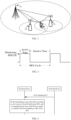
- FIG. 1 is a schematic diagram of a communication system 100 of an implementation of the present disclosure.
- a terminal device 110 is connected to a first network device 130 under a first communication system and a second network device 120 under a second communication system.
- the first network device 130 is a network device under Long Term Evolution (LTE)
- the second network device 120 is a network device under New Radio (NR).
- LTE Long Term Evolution
- NR New Radio
- Multiple cells may be included under the first network device 130 and the second network device 120.
- FIG. 1 is an example of the communication system of an implementation of the present disclosure, and implementations of the present disclosure are not limited to that shown in FIG. 1 .
- a communication system to which an implementation of the present disclosure is applied may include at least multiple network devices under the first communication system and/or multiple network devices under the second communication system.
- the system 100 shown in FIG. 1 may include one master network device under the first communication system and at least one secondary network device under the second communication system.
- the at least one secondary network device is respectively connected with the primary network device to form a multi-connection, and is respectively connected with the terminal device 110 to provide services for the terminal device 110.
- the terminal device 110 may establish connections simultaneously with the master network device and the secondary network device.
- connection established between the terminal device 110 and the primary network device 110 is a primary connection
- connection established between the terminal device 110 and the secondary network device is a secondary connection.
- Control signaling of the terminal device 110 may be transmitted through the primary connection
- data of the terminal device 110 may be transmitted through the primary connection and the secondary connection at the same time, or may be transmitted only through the secondary connection.
- first communication system and the second communication system in implementations of the present disclosure are different, but specific categories of the first communication system and the second communication system are not limited.
- the first communication system and the second communication system may be various communication systems, such as a Global System of Mobile communication (GSM) system, a Code Division Multiple Access (CDMA) system, a Wideband Code Division Multiple Access (WCDMA) system, a General Packet Radio Service (GPRS) system, a Long Term Evolution (LTE) system, an LTE Time Division Duplex (TDD) system, a Universal Mobile Telecommunication System (UMTS).
- GSM Global System of Mobile communication
- CDMA Code Division Multiple Access
- WCDMA Wideband Code Division Multiple Access
- GPRS General Packet Radio Service
- LTE Long Term Evolution
- TDD Time Division Duplex
- UMTS Universal Mobile Telecommunication System
- the primary network device and the secondary network device may be any access network devices.
- the access network device may be a Base Transceiver Station (BTS) in the GSM or the CDMA system, or may be a NodeB (NB) in the WCDMA system, or may be an Evolutional Node B (eNB or eNodeB) in the LTE system.
- BTS Base Transceiver Station
- NB NodeB
- eNB Evolutional Node B
- the access network device may be a base station (gNB) in a Next Generation Radio Access Network (NG RAN) or an NR system or a wireless controller in a Cloud Radio Access Network (CRAN).
- the access network device may be a relay station, an access point, a vehicle device, a wearable device or a network device in a future evolved Public Land Mobile Network (PLMN), etc.
- gNB base station
- NG RAN Next Generation Radio Access Network
- CRAN Cloud Radio Access Network
- PLMN Public Land Mobile Network
- the first network device 130 is the master network device
- the second network device 120 is the secondary network device.
- the first network device 130 may be an LTE network device, and the second network device 120 may be an NR network device. Or the first network device 130 may be an NR network device, and the second network device 120 may be an LTE network device. Or the first network device 130 and the second network device 120 may be both NR network devices. Or the first network device 130 may be a GSM network device or a CDMA network device etc., and the second network device 120 may be a GSM network device or a CDMA network device etc. Or the first network device 130 may be a Macrocell, and the second network device 120 may be a Microcell, a Picocell or a Femtocell, etc.
- the terminal device 110 may be any terminal device.
- the terminal device 110 includes, but not limited to:
- connection via a wired line such as connection via public switched telephone networks (PSTN), a digital subscriber line (DSL), a digital cable, and a direct cable; and/or another data connection/network; and/or via a wireless interface, for example, for a cellular network, a wireless local area network (WLAN), a digital television network such as a DVB-H network, a satellite network and an AM-FM broadcast transmitter; and/or an apparatus of another UE, which is configured to receive/transmit a communication signal; and/or an Internet of things (IoT) device.
- the UE configured to realize communication through a wireless interface may be referred to as a "wireless communication terminal", a "wireless terminal”, or a "mobile terminal".
- Examples of the mobile terminal include, but not limited to, a satellite or cellular phone, and a personal communications system (PCS) terminal that may combine a cellular radiotelephone with data processing, facsimile, and data communication capabilities; a radiotelephone, a pager, an Internet/intranet access, a Web browser, a notepad, a calendar, and/or a personal digital assistant (PDA) of a global positioning system (GPS) receiver; and a conventional laptop and/or palmtop receiver or other electronic apparatuses including radiotelephone transceivers.
- PCS personal communications system
- the UE may refer to an access terminal, UE, a user unit, a user station, a mobile station, a mobile platform, a remote station, a remote terminal, a mobile device, a user terminal, a terminal, a wireless communication device, a user agent, or a user apparatus.
- the access terminal may be a cellular phone, a cordless telephone, a session initiation protocol (SIP) telephone, a wireless local loop (WLL) station, a PDA, a handheld device having a wireless communication function, a computation device or other processing devices connected to a radio modem, a vehicle device, a wearable device, UE in a 5G network, or UE in the PLMN that will be evolved in the future, and the like.
- SIP session initiation protocol
- WLL wireless local loop
- a discontinuous reception (DRX) transmission mechanism is introduced in LTE.
- PDCCH blind PDCCH detection will be stopped at this time
- a basic mechanism of DRX is to configure a DRX cycle for a UE in a radio resource control (RRC) connected state.
- RRC radio resource control
- a DRX cycle consists of an active time and an inactive time.
- On Duration time, the UE monitors and receives the PDCCH; during "Opportunity for DRX" time, the UE does not receive the PDCCH to reduce power consumption.
- transmission of a paging message is also a DRX mechanism for a RRC idle state, and the DRX cycle is a cycle of the paging message in this case.
- time is divided into successive DRX cycles.
- a solution provided by the embodiments of the present disclosure is that if the base station determines that it is necessary to schedule the terminal in DRX on duration, it sends an energy-saving signal to the terminal which is used for waking up the terminal, so that the terminal starts a on duration timer in the DRX cycle for PDCCH detection; otherwise, if the base station determines that it is not necessary to schedule the terminal in DRX on duration, it instructs the terminal not to perform the PDCCH detection, thereby avoiding waste of detection power.
- DRX on duration is a time period from a starting time of a timer that is the DRX on duration timer started by the terminal device at the start position of the DRX cycle to an ending time or timeout of the timer.
- the energy-saving signal may also be used for, in addition to being used for waking up the terminal for the PDCCH detection, indicating information such as a target BWP and a configuration of PDCCH search space used by the terminal upon waking up.
- the 3rd generation partnership project (3GPP) currently discusses to support a dormancy behavior of Scell for the terminal.
- the so-called dormancy behavior of Scell means that the terminal does not monitor the PDCCH on the scell, and only performs related operations, such as channel state information (CSI) measurement, automatic gain control (AGC), beam management, and radio resource management (RRM) measurement.
- CSI channel state information
- AGC automatic gain control
- RRM radio resource management
- 3GPP agrees that the dormancy behavior of Scell is realized by switching the terminal to the dormant BWP on the Scell, see the following conclusion.
- the following conclusion further clarifies that an indication signaling based on layer 1 (L1) is used for indicating whether the terminal triggers the dormancy behavior of Scell, that is, whether to switch to the dormant BWP.
- the L1 signaling in the embodiments of the present disclosure may be PDCCH that is used to transmit DCI.
- a first type of DCI is not only used for indicating whether the terminal device operates on the dormant BWP in the secondary cell, but also used for scheduling data
- a second type of DCI is only used for indicating whether the terminal device operates on the dormant BWP in the secondary cell, but is not used for scheduling data.
- the terminal device may switch a status of the secondary cell according to content of the signaling, and may transmit data scheduled by the network device according to a resource location indicated in the signaling. If the terminal device acquires the second type of DCI, the terminal device may only switch the status of the secondary cell according to the content of the signaling.
- the embodiments of the present disclosure provide a method for determining a downlink control information type, so that the terminal device may determine which type of DCI the acquired DCI belongs to. As shown in FIG. 3 , the method includes steps S310 to S320.
- a network device sends DCI, and a terminal device receives the DCI.
- the terminal device determines a type of DCI according to a bit value of a first bit field in the DCI; and/or, in some example not covered by the invention, the terminal device determines the type of DCI according to a radio network tempory identity (RNTI) used for scrambling a cyclic redundancy check (CRC) of the DCI.
- RNTI radio network tempory identity
- CRC cyclic redundancy check
- the DCI includes a first type of DCI and a second type of DCI, the first type of DCI is used for scheduling data and indicating that the terminal device operates on a dormant bandwidth part (BWP) or a non-dormant BWP in a secondary cell, and the second type of DCI is used for indicating that the terminal device operates on the dormant BWP or the non-dormant BWP in the secondary cell.
- BWP dormant bandwidth part
- the first type of DCI is also used for, in addition to being used for indicating an operating status of the terminal device on the secondary cell, scheduling data, and the second type of DCI is only used for indicating the operating status of the terminal device on the secondary cell.
- the embodiments of the present disclosure implicitly distinguish the first type of DCI from the second type of DCI based on different bit values of the first bit field in the DCI or different RNTIs for scrambling the CRC of the DCI, which does not require a special signaling for indication, thereby saving signaling overhead.
- the first bit field may be any one or more bit fields in the DCI.
- the first bit field can be any of the following: a frequency domain resource assignment field, a time domain resource assignment field, and a hybrid automatic repeat request (HARQ) process number field.
- HARQ hybrid automatic repeat request
- bit values or value combinations that cannot be used for actual data transmission. Therefore, these bit values or value combinations may be used for indicating the type of DCI.
- the terminal device may determine the type of DCI according to a bit value of the frequency domain resource assignment field.
- the present disclosure may determine the type of DCI according to an agreed bit value of the frequency domain resource assignment field. For example, when the bit value is a first value, the DCI is the first type of DCI; when the bit value is a second value, the DCI is the second type of DCI.
- the terminal device may determine that the DCI is the second type of DCI; if bit values of the frequency domain resource assignment field are not all 0, the terminal device may determine the DCI is the first type of DCI. This is because for normal frequency domain resource assignment, a certain number of physical resource blocks (PRB) will be assigned to the terminal within an active BWP range. If the bit value is 0, it means that there is no PRB assignment, and accordingly, the DCI cannot be used for data scheduling, the terminal device may determine that the DCI is the second type of DCI.
- PRB physical resource blocks
- the DCI uses four bits to represent the frequency domain resource assignment field, when values of the four bits in the DCI are 0000, it means that the DCI is the second type of DCI; when the values of the four bits in the DCI are not 0000, it means that the DCI is the first type of DCI.
- the above description is only based on four bits.
- the number of bits used by the frequency domain resource assignment field is related to a carrier bandwidth or BWP, and is not limited to four bits.
- the embodiments of the present disclosure implicitly indicate the type of DCI by multiplexing the frequency domain resource assignment field, which can save signaling overhead.
- the method for distinguishing the DCI through the bit value is simple and does not increase processing complexity for the terminal device.
- the terminal device may determine the type of DCI according to a bit value of the time domain resource assignment field.
- the present disclosure may determine the type of DCI according to an agreed bit value of the time domain resource assignment field. For example, when the bit value is a first value, the DCI is the first type of DCI; when the bit value is a second value, the DCI is the second type of DCI.
- the second value may be 0000 or 1111, that is, if the bit value of the time domain resource assignment field is 0000 or 1111, the terminal device may determine that the DCI is the second type of DCI; if the bit value of the time domain resource assignment field is not 0000 and 1111, the terminal device may determine the DCI is the first type of DCI.
- the terminal device also determines target information according to the bit value of the time domain resource assignment field; the terminal device determines the type of DCI according to the target information.
- the target information includes at least one of the following information: k0, k2, information of a time domain resource assignment table that needs to be read by the terminal device, L, S;
- k0 represents a slot interval between a slot where the DCI is located and a slot of a physical downlink shared channel (PDSCH) scheduled by the DCI
- k2 represents a slot interval between the slot where the DCI is located and a slot of a physical uplink shared channel (PUSCH) scheduled by the DCI
- L represents a number of symbols assigned by a time domain resource
- S represents a starting position of a time domain symbol used by the PDSCH or the PUSCH scheduled by the DCI.
- the time domain resource assignment field may be represented by four bits, and the bit value may be any value between 0-15. Assuming that the bit value is m, m may represent a row index of the time domain resource assignment table (a row index number starts from 0), that is, the row index of the time domain resource assignment table that needs to be read by the terminal device is m.
- the time domain resource assignment table may include information, such as k0, k2, L, S.
- the terminal device may read the information in the time domain resource assignment table according to the row index indicated by the time domain resource assignment field, so as to determine k0, k2, L, and S.
- the time domain resource assignment table may be configured by the network device to the terminal device through a RRC signaling.
- the terminal device may determine the type of DCI according to k0.
- the terminal device may determine that the DCI is the second type of DCI.
- k0 being not configured may also mean that k0 is empty.
- k0 represents the slot interval between DCI and the PDSCH scheduled by the DCI
- a value of k0 usually does not exceed 32. If k0 determined by the terminal device exceeds 32, it means that k0 is the invalid value, and the terminal device may determine that DCI is of the second type of DCI.
- the terminal device may determine the type of DCI according to k2.
- the terminal device may determine that the DCI is the second type of DCI.
- K2 being not configured may also mean that k2 is empty.
- k2 represents the slot interval between DCI and the PUSCH scheduled by the DCI
- a value of k2 usually does not exceed 32. If k2 determined by the terminal device exceeds 32, it means that k2 is the invalid value, and the terminal device may determine that DCI is of the second type of DCI.
- the embodiments of the present disclosure use some unreasonable values to implicitly indicate the type of DCI without requiring the special signaling for indication, which can save signaling overhead.
- the terminal device may determine the type of DCI according to the information of the time domain resource assignment table that needs to be read by the terminal device.
- the terminal device may determine that the DCI is the second type of DCI.
- the terminal device may consider the DCI is the second type of DCI.
- the terminal device may consider the DCI is the second type of DCI.
- the terminal device may consider the DCI is the second type of DCI.
- the terminal device may determine the type of DCI according to L.
- L represents the continuous symbol length of the PDSCH or PUSCH, if L is configured as 0, it means that there is no valid time domain symbol assignment. Therefore, the DCI cannot be used for data scheduling, and the terminal device may consider the DCI is the second type of DCI.
- the terminal device may also consider the DCI is the second type of DCI.
- the terminal device may determine the type of DCI according to S.
- the terminal device may determine that the DCI is the second type of DCI. This is because S represents the starting position of the time domain symbols used to transmit the PDSCH or PUSCH scheduled by DCI. If S determined according to the time domain resource assignment field is greater than or equal to the number of symbols contained in one slot, the terminal device may consider this is an unreasonable configuration and cannot be used for data transmission, and the DCI can be determined as the second type of DCI.
- the terminal device can consider this as an unreasonable configuration and cannot be used for data transmission, and may determine that the DCI is the second type of DCI.
- the terminal device may determine the type of DCI according to the value of the bits in the HARQ process number field.
- the present disclosure may determine the type of DCI according to an agreed bit value of the HARQ process number field. For example, when the bit value is a third value, the DCI is the first type of DCI; when the bit value is a fourth value, the DCI is the second type of DCI.
- the fourth value may be 0000 or 1111, that is, if the bit value of the HARQ process number field is 0000 or 1111, the terminal device may determine that the DCI is the second type of DCI; if the bit value of the HARQ process number field is not 0000 and 1111, the terminal device may determine the DCI is the first type of DCI.
- the terminal device can distinguish different types of DCI according to different RNTIs used for scrambling the CRC of the DCI.
- the terminal device may determine the DCI is the first type of DCI; if the RNTI used for scrambling the CRC of the DCI is a second RNTI, the terminal device may determine that the DCI is the second type of DCI.
- the first RNTI is different from the second RNTI.
- the terminal device may use the RNTI to descramble the CRC of the DCI. If the first RNTI can be used for descrambling, that is, the PDCCH is correctly received, the terminal device may determine the DCI is the first type of DCI; If the second RNTI can be used for descrambling, that is, the PDCCH is correctly received, the terminal device may determine that the DCI is the second type of DCI.
- the first RNTI may be, for example, a cell RNTI (C-RNTI).
- C-RNTI cell RNTI
- the second RNTI may be sent by the network device to the terminal device through the RRC signaling, or the second RNTI may be pre-configured in the terminal device.
- the embodiments of the present disclosure may determine the type of DCI in any of the manners described above, or may determine the type of DCI in a combination of the manners described above. For example, the terminal device may determine the type of DCI according to the bit value of the frequency domain resource assignment field and the bit value of the time domain resource assignment field. If the bit value of the frequency domain resource assignment field is 0000, the terminal device may determine that the DCI is the second type of DCI; if the bit value of the frequency domain resource assignment field is not 0000, the terminal device may further determine the type of DCI according to the bit value of the time domain resource assignment field.
- the terminal device may determine that the DCI is the second type of DCI; if the bit value of the time domain resource assignment field is not 0000 or 1111, the terminal device may determine the DCI is the first type of DCI.
- FIG. 4 is a schematic block diagram of a terminal device provided by an embodiment of the present disclosure.
- the terminal device may be any terminal device described above.
- the terminal device 400 shown in FIG. 4 includes a communication unit 410 and a processing unit 420, where: the communication unit 410 is configured to receive downlink control information (DCI); and
- DCI downlink control information
- the processing unit 420 is configured to determine a type of the DCI according to a bit value of a first bit field in the DCI, and/or in some example not covered by the invention, determine the type of the DCI according to a radio network tempory identity (RNTI) used for scrambling a cyclic redundancy check (CRC) of the DCI.
- RNTI radio network tempory identity
- CRC cyclic redundancy check
- the DCI includes a first type of DCI and a second type of DCI, the first type of DCI is used for scheduling data and indicating that the terminal device operates on a dormant bandwidth part (BWP) or a non-dormant BWP in a secondary cell, and the second type of DCI is used for indicating that the terminal device operates on the dormant BWP or the non-dormant BWP in the secondary cell.
- BWP dormant bandwidth part
- the first bit field includes at least one of the following: a frequency domain resource assignment field, a time domain resource assignment field, and a hybrid automatic repeat request (HARQ) process number field
- HARQ hybrid automatic repeat request
- the first bit field is the time domain resource assignment field
- the processing unit 420 is configured to: determine the DCI is the first type of DCI, if a bit value of the time domain resource assignment field is a first value; and/or, determine the DCI is the second type of DCI, if the bit value of the time domain resource assignment field is a second value.
- the second value is 0000 or 1111.
- the first bit field is the time domain resource assignment field
- the processing unit 420 is configured to: determine target information, according to a bit value of the time domain resource assignment field; and determine the type of the DCI according to the target information, and the target information includes at least one of the following information: k0, k2, information of a time domain resource assignment table that needs to be read by the terminal device, L, S; where k0 represents a slot interval between a slot where the DCI is located and a slot of a physical downlink shared channel (PDSCH) scheduled by the DCI, and k2 represents a slot interval between the slot where the DCI is located and a slot of a physical uplink shared channel (PUSCH) scheduled by the DCI, L represents a number of symbols assigned by a time domain resource, and S represents a starting position of a time domain symbol used by the PDSCH or the PUSCH scheduled by the DCI.
- k0 represents a slot interval between a slot where the DCI is located and a slot of a physical downlink shared
- the target information is k0
- the processing unit 420 is configured to: determine the DCI is the second type of DCI, if k0 is infinity or an invalid value or k0 is not configured.
- the target information is k2
- the processing unit 420 is configured to: determine the DCI is the second type of DCI, if k2 is infinity or an invalid value or k0 is not configured.
- the target information is the information of the time domain resource assignment table that needs to be read by the terminal device
- the processing unit 420 is configured to: determine the DCI is the second type of DCI, if an index number of a row in the time domain resource assignment table that needs to be read by the terminal device exceeds a range of index numbers that a configured time domain resource assignment table is capable of providing; and/or, determine the DCI is the second type of DCI, if k0 in the time domain resource assignment table that needs to be read by the terminal device is infinite or an invalid value or k0 is not configured by the time domain resource assignment table; and /or, determine the DCI is the second type of DCI, if k2 in the time domain resource assignment table that needs to be read by the terminal device is infinite or an invalid value or k2 is not configured by the time domain resource assignment table.
- the target information is L
- the processing unit 420 is configured to determine the DCI is the second type of DCI, if L is 0.
- the target information is S
- the processing unit 420 is configured to determine the DCI is the second type of DCI, if S is not configured or S is greater than 13.
- the first bit field is the frequency domain resource assignment field
- the processing unit 420 is configured to determine the DCI is the second type of DCI, if all bit values of the frequency domain resource assignment field are 0.
- the first bit field is the HARQ process number field
- the processing unit 420 is configured to determine the DCI is the first type of DCI, if a bit value of the HARQ process number field is a third value; and/or, determine the DCI is the second type of DCI, if the bit value of the HARQ process number field is a fourth value.
- the fourth value is 0000 or 1111.
- the processing unit 420 is configured to determine the DCI is the first type of DCI, if the RNTI used for scrambling the CRC of the DCI is a first RNTI; and determine the DCI is the second type of DCI, if the RNTI used for scrambling the CRC of the DCI is a second RNTI, and the first RNTI is different from the second RNTI.
- the first RNTI is a cell RNTI.
- the second RNTI is a RNTI received by the terminal device and sent by a network device through a radio resource control signaling, or the second RNTI is a pre-configured.
- FIG. 5 is a schematic block diagram of a network device provided by an embodiment of the present disclosure.
- the network device may be any of the network devices described above.
- the network device 500 shown in FIG. 5 includes a communication unit 510, where: the communication unit 510 is configured to send downlink control information (DCI), and the DCI includes a first bit field, and a bit value of the first bit field is used for indicating a type of the DCI, and/or in some example not covered by the invention, a radio network tempory identity (RNTI) used for scrambling a cyclic redundancy check (CRC) of the DCI is used for indicating the type of the DCI.
- DCI downlink control information
- RNTI radio network tempory identity
- CRC cyclic redundancy check
- the DCI includes a first type of DCI and a second type of DCI, the first type of DCI is used for scheduling data and indicating that the terminal device operates on a dormant bandwidth part (BWP) or a non-dormant BWP in a secondary cell, and the second type of DCI is used for indicating that the terminal device operates on the dormant BWP or the non-dormant BWP in the secondary cell.
- BWP dormant bandwidth part
- the first bit field includes at least one of the following: a frequency domain resource assignment field, a time domain resource assignment field, and a hybrid automatic repeat request (HARQ) process number field.
- HARQ hybrid automatic repeat request
- a bit value of the time domain resource assignment field being a first value is used for indicating that the DCI is the first type of DCI
- the bit value of the time domain resource assignment field being a second value is used for indicating the DCI is the second type of DCI.
- the second value is 0000 or 1111.
- the bit value of the time domain resource assignment field is used for determining target information, and the target information is used for indicating the type of the DCI, and includes at least one of the following information: k0, k2, information of a time domain resource assignment table that needs to be read by the terminal device, L, S; where k0 represents a slot interval between a slot where the DCI is located and a slot of a physical downlink shared channel (PDSCH) scheduled by the DCI, and k2 represents a slot interval between the slot where the DCI is located and a slot of a physical uplink shared channel (PUSCH) scheduled by the DCI, L represents a number of symbols assigned by a time domain resource, and S represents a starting position of a time domain symbol used by the PDSCH or the PUSCH scheduled by the DCI.
- k0 represents a slot interval between a slot where the DCI is located and a slot of a physical downlink shared channel (PDSCH) scheduled by the DCI
- k2 represents a slot interval between the slot
- k0 being infinity or an invalid value or k0 being not configured is used for indicating the DCI is the second type of DCI.
- k2 being infinity or an invalid value or k2 being not configured is used for indicating the DCI is the second type of DCI.
- an index number of a row in the time domain resource assignment table that needs to be read by the terminal device exceeding a range of index numbers that a configured time domain resource assignment table is capable of providing is used for indicating the DCI is the second type of DCI; and/or k0 in the time domain resource assignment table that needs to be read by the terminal device being infinite or an invalid value or k0 being not configured by the time domain resource assignment table is used for indicating the DCI is the second type of DCI; and/or k2 in the time domain resource assignment table that needs to be read by the terminal device being infinite or an invalid value or k2 being not configured by the time domain resource assignment table is used for indicating the DCI is the second type of DCI.
- L being 0 is used for indicating the DCI is the second type of DCI.
- S being not configured or S being greater than 13 is used for indicating the DCI is the second type of DCI.
- all bit values of the frequency domain resource assignment field being 0 is used for indicating the DCI is the second type of DCI.
- a bit value of the HARQ process number field being a third value is used for indicating that the DCI is the first type of DCI; and/or, the bit value of the HARQ process number field being a fourth value is used for indicating the DCI is the second type of DCI.
- the fourth value is 0000 or 1111.
- the RNTI used for scrambling the CRC of the DCI being a first RNTI is used for indicating that the DCI is the first type of DCI; and the RNTI used for scrambling the CRC of the DCI being a second RNTI is used for indicating the DCI is the second type of DCI, and the first RNTI is different from the second RNTI.
- the first RNTI is a cell RNTI.
- the second RNTI is a RNTI received by the terminal device and sent by a network device through a radio resource control signaling, or the second RNTI is a pre-configured.
- the above-mentioned communication module may be a communication interface or a transceiver, or an input/output interface of a communication chip or a system-on-chip.
- the aforementioned determining module may be one or more processors.
- FIG. 6 is a schematic structural diagram of a communication device 600 according to an embodiment of the present disclosure.
- the communication device 600 shown in FIG. 6 includes a processor 610.
- the processor 610 may invoke a computer program from a memory and run the computer program, to implement the method in the embodiments of the present disclosure.
- the communication device 600 may further include a memory 620.
- the processor 610 may invoke the computer program from the memory 620 and run the computer program, to implement the method in the embodiments of the present disclosure.
- the memory 620 may be a component independent of the processor 610, or may be integrated into the processor 610.
- the communication device 600 may further include a transceiver 630.
- the processor 610 may control the transceiver 630 to communicate with another device, and specifically, the transceiver 630 may transmit information or data to another device, or receive information or data transmitted by another device.
- the transceiver 630 may include a transmitter and a receiver.
- the transceiver 630 may further include an antenna. There may be one or more antennas.
- the communication device 600 may be the network device in the embodiments of the present disclosure, and the communication device 600 can implement corresponding procedures implemented by the network device in various methods in the embodiments of the present disclosure. For brevity, details are not described herein again.
- the communication device 600 may be the mobile terminal/terminal in the embodiments of the present disclosure, and the communication device 600 can implement corresponding procedures implemented by the mobile terminal/terminal device in various methods in the embodiments of the present disclosure. For brevity, details are not described herein again.
- FIG. 7 is a schematic structural diagram of a device according to an embodiment of the present disclosure.
- the device 700 shown in FIG. 7 includes a processor 710.
- the processor 710 may invoke a computer program from a memory and run the computer program, to implement the method in the embodiments of the present disclosure.
- the device 700 may further include a memory 720.
- the processor 710 may invoke the computer program from the memory 720 and run the computer program, to implement the method in the embodiments of the present disclosure.
- the memory 720 may be a component independent of the processor 710, or may be integrated into the processor 710.
- the device 700 may further include an input interface 730.
- the processor 710 may control the input interface 730 to communicate with another device or device, and specifically, the input interface 730 may obtain information or data transmitted by another device or device.
- the device 700 may further include an output interface 740.
- the processor 710 may control the output interface 740 to communicate with another device or device, and specifically, the output interface 740 may output information or data to another device or device
- the device may be applied in the network device according to embodiments of the present disclosure, and the device can implement corresponding procedures implemented by the network device in various methods in the embodiments of the present disclosure.
- the device can implement corresponding procedures implemented by the network device in various methods in the embodiments of the present disclosure.
- details are not described herein again.
- the device may be applied to the mobile terminal/terminal device in the embodiments of the present disclosure, and the device can implement corresponding procedures implemented by the mobile terminal/terminal device in various methods in the embodiments of the present disclosure.
- the device may be applied to the mobile terminal/terminal device in the embodiments of the present disclosure, and the device can implement corresponding procedures implemented by the mobile terminal/terminal device in various methods in the embodiments of the present disclosure.
- details are not described herein again.
- the device mentioned in the embodiments of the present disclosure may be a chip, which may also be referred to as a system-level chip, a system chip, a chip system, a system on chip, or the like.
- FIG. 8 is a schematic structural diagram of a communication system 800 according to an embodiment of the present disclosure.
- the communication system 800 shown in FIG. 8 includes a terminal device 810 and a network device 820.
- the terminal device 810 can implement corresponding functions implemented by the terminal device in the foregoing method and the network device 820 can implement corresponding functions implemented by the network device in the foregoing method. For brevity, details are not described herein again.
- the processor of the embodiments of the present disclosure may be an integrated circuit chip, has a signal processing capability, the steps of the foregoing method embodiment may be implemented by using a hardware integrated logic circuit in the processor and/or implemented by using an instruction in a software form.
- the foregoing processor may be a general purpose processor, a digital signal processor (DSP), a field programmable gate array (FPGA), an application specific integrated circuit (ASIC) or another programmable logic device, a transistor logic device, or a discrete hardware component.
- DSP digital signal processor
- FPGA field programmable gate array
- ASIC application specific integrated circuit
- the foregoing general purpose processor may be a microprocessor, or may be any conventional processor, or the like.
- Steps of the methods disclosed with reference to the embodiments of the present invention may be directly executed and completed by means of a hardware decoding processor, or may be executed and completed by using a combination of hardware and software modules in the decoding processor.
- the software module may be located in a mature storage medium in the field, such as a random access memory, a flash memory, a read-only memory, a programmable read-only memory, an electrically-erasable programmable memory, or a register.
- the storage medium is located in the memory, and the processor reads information in the memory and completes the steps in the foregoing method embodiments in combination with hardware of the processor.
- the memory in the embodiments of the present disclosure may be a volatile memory or a non-volatile memory, or may include both a volatile memory and a non-volatile memory.
- the non-volatile memory may be a read-only memory (ROM), a programmable ROM (PROM), an erasable PROM (EPROM), an electrically EPROM (EEPROM), or a flash memory.
- the volatile memory may be a random access memory (RAM), and is used as an external cache.
- RAM random access memory
- DRAM dynamic random access memory
- SDRAM synchronous dynamic random access memory
- DDRSDRAM double data rate synchronous dynamic random access memory
- ESDRAM enhanced synchronous dynamic random access memory
- SLDRAM synclink dynamic random access memory
- DRRAM direct rambus random access memory
- the memory is an example but is not intended for limitation.
- the memory in the embodiments of the present disclosure may alternatively be a static RAM (SRAM), a dynamic RAM (DRAM), a synchronous DRAM (SDRAM), a double data rate SDRAM (DDR SDRAM), an enhanced SDRAM (ESDRAM), a synch link DRAM (SLDRAM), a direct rambus RAM (DR RAM), and the like. That is, the memory described in this embodiment of the present disclosure is intended to include but is not limited to these memories and any other suitable type of memory.
- An embodiment of the present disclosure further provides a computer readable storage medium.
- the computer readable storage medium is configured to store a computer program.
- the computer readable storage medium may be applied to the network device in the embodiments of the present disclosure, and the computer program enables a computer to execute a corresponding procedure implemented by the network device in the methods of the embodiments of the present disclosure.
- the computer program enables a computer to execute a corresponding procedure implemented by the network device in the methods of the embodiments of the present disclosure.
- the computer readable storage medium may be applied to the mobile terminal/terminal device in the embodiments of the present disclosure, and the computer program enables the computer to execute a corresponding procedure implemented by the mobile terminal/terminal device in the methods of the embodiments of the present disclosure.
- the computer program enables the computer to execute a corresponding procedure implemented by the mobile terminal/terminal device in the methods of the embodiments of the present disclosure.
- the present disclosure further provides a computer program product.
- the computer program product includes a computer program instruction.
- the computer program product may be applied to the network device in the embodiments of the present disclosure, and the computer program instruction enables the computer to execute a corresponding procedure implemented by the network device in the methods of the embodiments of the present disclosure.
- the computer program instruction enables the computer to execute a corresponding procedure implemented by the network device in the methods of the embodiments of the present disclosure.
- the computer program product may be applied to the mobile terminal/terminal device in the embodiments of the present disclosure, and the computer program instruction enables the computer to execute a corresponding procedure implemented by the mobile terminal/terminal device in the methods of the embodiments of the present disclosure.
- the computer program instruction enables the computer to execute a corresponding procedure implemented by the mobile terminal/terminal device in the methods of the embodiments of the present disclosure.
- the present disclosure further provides a computer program.
- the computer program may be applied to the network device in the embodiments of the present disclosure, and when run on a computer, the computer program instruction enables the computer to execute a corresponding procedure implemented by the network device in the methods of the embodiments of the present disclosure.
- the computer program instruction enables the computer to execute a corresponding procedure implemented by the network device in the methods of the embodiments of the present disclosure.
- the computer program may be applied to the mobile terminal/terminal device in the embodiments of the present disclosure, and when run on a computer, the computer program instruction enables the computer to execute a corresponding procedure implemented by the mobile terminal/terminal device in the methods of the embodiments of the present disclosure.
- the computer program instruction enables the computer to execute a corresponding procedure implemented by the mobile terminal/terminal device in the methods of the embodiments of the present disclosure.
- the disclosed system, apparatus, and method may be implemented in other manners.
- the apparatus embodiments described above are merely examples.
- the unit division is merely logical function division, and there may be other division manners in actual implementation.
- a plurality of units or components may be combined or integrated into another system, or some features may be ignored or not performed.
- the displayed or discussed mutual couplings or direct couplings or communication connections may be implemented by using some interfaces.
- the indirect couplings or communication connections between the apparatuses or units may be implemented in electrical, mechanical, or other forms.
- the units described as separate parts may or may not be physically separate, and the parts displayed as units may or may not be physical units, may be located in one position, or may be distributed on multiple network units. Some of or all of the units may be selected according to actual needs to achieve the objectives of the solutions of the embodiments.
- the functions When the functions are implemented in the form of a software functional unit and sold or used as an independent product, the functions may be stored in a computer-readable storage medium.
- the software product is stored in a storage medium, and includes several instructions for instructing a computer device (which may be a personal computer, a server, or a network device) to perform all or some of the steps of the methods described in the embodiments of the present disclosure.
- the foregoing storage medium includes: any medium that can store program code, such as a USB flash drive, a removable hard disk, a read-only memory (ROM), a random access memory (RAM), a magnetic disk, or an optical disc.
Landscapes
- Engineering & Computer Science (AREA)
- Signal Processing (AREA)
- Computer Networks & Wireless Communication (AREA)
- Mobile Radio Communication Systems (AREA)
Claims (4)
- Verfahren zum Bestimmen eines Downlinksteuerinformationstyps, das Folgendes umfasst:Empfangen (310) von Downlinksteuerinformationen, DCI, von einer Endgerätevorrichtung undBestimmen (S320) eines Typs der DCI durch die Endgerätevorrichtung gemäß einem Bitwert eines ersten Bitfeldes in den DCI;wobei die DCI ein erster Typ von DCI und ein zweiter Typ von DCI sind, wobei der erste Typ von DCI zum Planen von Daten und zum Anzeigen, dass die Endgerätevorrichtung in einem ruhenden Bandbreitenteil, BWP, oder einem nicht ruhenden BWP in einer sekundären Zelle betrieben wird, verwendet wird und der zweite Typ von DCI zum Anzeigen, dass die Endgerätevorrichtung im ruhenden BWP oder im nicht ruhenden BWP in der sekundären Zelle betrieben wird, verwendet wird,dadurch gekennzeichnet, dass das erste Bitfeld ein Zeitdomänenressourcenzuweisungsfeld ist und das Bestimmen des Typs der DCI durch die Endgerätevorrichtung gemäß dem Bitwert des ersten Bitfeldes in den DCI Folgendes umfasst:Bestimmen von Zielinformationen durch die Endgerätevorrichtung gemäß einem Bitwert des Zeitdomänenressourcenzuweisungsfeldes undBestimmen des Typs der DCI durch die Endgerätevorrichtung gemäß den Zielinformationen, wobei die Zielinformationen mindestens eine der folgenden Informationen umfassen: k0, k2, Informationen einer Zeitdomänenressourcenzuweisungstabelle, die von der Endgerätevorrichtung gelesen werden müssen, L, S;wobei k0 ein Schlitzintervall zwischen einem Schlitz, in dem sich die DCI befinden, und einem Schlitz eines gemeinsam verwendeten physischen Downlinkkanals, PDSCH, repräsentiert, das von den DCI geplant wird, und k2 ein Schlitzintervall zwischen dem Schlitz, in dem sich die DCI befinden, und einem Schlitz eines gemeinsam verwendeten physischen Uplinkkanals, PUSCH, repräsentiert, das von den DCI geplant wird, L eine Anzahl von Symbolen repräsentiert, die von einer Zeitdomänenressource zugewiesen werden, und S eine Startposition eines vom PDSCH oder vom PUSCH verwendeten Zeitdomänensymbols repräsentiert, die von den DCI geplant wird.
- Verfahren zum Bestimmen eines Downlinksteuerinformationstyps, das Folgendes umfasst:Senden (S310) von Downlinksteuerinformationen, DCI, durch eine Netzwerkvorrichtung, wobei die DCI ein erstes Bitfeld umfassen und ein Bitwert des ersten Bitfeldes zum Anzeigen eines Typs der DCI verwendet wird;wobei die DCI ein erster Typ von DCI und ein zweiter Typ von DCI sind, wobei der erste Typ von DCI zum Planen von Daten und zum Anzeigen, dass eine Endgerätevorrichtung in einem ruhenden Bandbreitenteil, BWP, oder einem nicht ruhenden BWP in einer sekundären Zelle betrieben wird, verwendet wird und der zweite Typ von DCI zum Anzeigen, dass die Endgerätevorrichtung im ruhenden BWP oder im nicht ruhenden BWP in der sekundären Zelle betrieben wird, verwendet wird,dadurch gekennzeichnet, dass das erste Bitfeld ein Zeitdomänenressourcenzuweisungsfeld ist, ein Bitwert des Zeitdomänenressourcenzuweisungsfeldes zum Bestimmen von Zielinformationen verwendet wird und die Zielinformationen zum Anzeigen des Typs der DCI verwendet werden und mindestens eine der folgenden Informationen umfassen: k0, k2, Informationen einer Zeitdomänenressourcenzuweisungstabelle, die von der Endgerätevorrichtung gelesen werden müssen, L, S;wobei k0 ein Schlitzintervall zwischen einem Schlitz, in dem sich die DCI befinden, und einem Schlitz eines gemeinsam verwendeten physischen Downlinkkanals (PDSCH) repräsentiert, das von den DCI geplant wird, und k2 ein Schlitzintervall zwischen dem Schlitz, in dem sich die DCI befinden, und einem Schlitz eines gemeinsam verwendeten physischen Uplinkkanals (PUSCH) repräsentiert, das von den DCI geplant wird, L eine Anzahl von Symbolen repräsentiert, die von einer Zeitdomänenressource zugewiesen werden, und S eine Startposition eines vom PDSCH oder vom PUSCH verwendeten Zeitdomänensymbols repräsentiert, die von den DCI geplant wird.
- Endgerätevorrichtung (400), die Folgendes umfasst:eine Kommunikationseinheit (410), die dazu ausgelegt ist, Downlinksteuerinformationen, DCI, zu empfangen; undeine Verarbeitungseinheit (420), die dazu ausgelegt ist, einen Typ der DCI gemäß einem Bitwert eines ersten Bitfeldes in den DCI zu bestimmen;wobei die DCI ein erster Typ von DCI und ein zweiter Typ von DCI sind, wobei der erste Typ von DCI zum Planen von Daten und zum Anzeigen, dass die Endgerätevorrichtung in einem ruhenden Bandbreitenteil, BWP, oder einem nicht ruhenden BWP in einer sekundären Zelle betrieben wird, verwendet wird und der zweite Typ von DCI zum Anzeigen, dass die Endgerätevorrichtung im ruhenden BWP oder im nicht ruhenden BWP in der sekundären Zelle betrieben wird, verwendet wird,dadurch gekennzeichnet, dass das erste Bitfeld ein Zeitdomänenressourcenzuweisungsfeld ist und die Verarbeitungseinheit zu Folgendem ausgelegt ist:Bestimmen von Zielinformationen gemäß einem Bitwert des Zeitdomänenressourcenzuweisungsfeldes undBestimmen des Typs der DCI gemäß den Zielinformationen, wobei die Zielinformationen mindestens eine der folgenden Informationen umfassen: k0, k2, Informationen einer Zeitdomänenressourcenzuweisungstabelle, die von der Endgerätevorrichtung gelesen werden müssen, L, S;wobei k0 ein Schlitzintervall zwischen einem Schlitz, in dem sich die DCI befinden, und einem Schlitz eines gemeinsam verwendeten physischen Downlinkkanals (PDSCH) repräsentiert, das von den DCI geplant wird, und k2 ein Schlitzintervall zwischen dem Schlitz, in dem sich die DCI befinden, und einem Schlitz eines gemeinsam verwendeten physischen Uplinkkanals (PUSCH) repräsentiert, das von den DCI geplant wird, L eine Anzahl von Symbolen repräsentiert, die von einer Zeitdomänenressource zugewiesen werden, und S eine Startposition eines vom PDSCH oder vom PUSCH verwendeten Zeitdomänensymbols repräsentiert, die von den DCI geplant wird.
- Netzwerkvorrichtung (500) zum Bestimmen eines Downlinksteuerinformationstyps, die Folgendes umfasst:eine Kommunikationseinheit (510), die dazu ausgelegt ist, Downlinksteuerinformationen, DCI, zu senden, wobei die DCI ein erstes Bitfeld umfassen und ein Bitwert des ersten Bitfeldes zum Anzeigen eines Typs der DCI verwendet wird;wobei die DCI ein erster Typ von DCI und ein zweiter Typ von DCI sind, wobei der erste Typ von DCI zum Planen von Daten und zum Anzeigen, dass eine Endgerätevorrichtung in einem ruhenden Bandbreitenteil, BWP, oder einem nicht ruhenden BWP in einer sekundären Zelle betrieben wird, verwendet wird und der zweite Typ von DCI zum Anzeigen, dass die Endgerätevorrichtung im ruhenden BWP oder im nicht ruhenden BWP in der sekundären Zelle betrieben wird, verwendet wird,dadurch gekennzeichnet, dass das erste Bitfeld ein Zeitdomänenressourcenzuweisungsfeld ist, ein Bitwert des Zeitdomänenressourcenzuweisungsfeldes zum Bestimmen von Zielinformationen verwendet wird und die Zielinformationen zum Anzeigen des Typs der DCI verwendet werden und mindestens eine der folgenden Informationen umfassen: k0, k2, Informationen einer Zeitdomänenressourcenzuweisungstabelle, die von der Endgerätevorrichtung gelesen werden müssen, L, S;wobei k0 ein Schlitzintervall zwischen einem Schlitz, in dem sich die DCI befinden, und einem Schlitz eines gemeinsam verwendeten physischen Downlinkkanals (PDSCH) repräsentiert, das von den DCI geplant wird, und k2 ein Schlitzintervall zwischen dem Schlitz, in dem sich die DCI befinden, und einem Schlitz eines gemeinsam verwendeten physischen Uplinkkanals (PUSCH) repräsentiert, das von den DCI geplant wird, L eine Anzahl von Symbolen repräsentiert, die von einer Zeitdomänenressource zugewiesen werden, und S eine Startposition eines vom PDSCH oder vom PUSCH verwendeten Zeitdomänensymbols repräsentiert, die von den DCI geplant wird.
Applications Claiming Priority (1)
| Application Number | Priority Date | Filing Date | Title |
|---|---|---|---|
| PCT/CN2019/116801 WO2021088017A1 (zh) | 2019-11-08 | 2019-11-08 | 用于确定下行控制信息类型的方法及设备 |
Publications (3)
| Publication Number | Publication Date |
|---|---|
| EP4009706A1 EP4009706A1 (de) | 2022-06-08 |
| EP4009706A4 EP4009706A4 (de) | 2022-08-03 |
| EP4009706B1 true EP4009706B1 (de) | 2023-10-04 |
Family
ID=75848170
Family Applications (1)
| Application Number | Title | Priority Date | Filing Date |
|---|---|---|---|
| EP19951349.0A Active EP4009706B1 (de) | 2019-11-08 | 2019-11-08 | Verfahren zur bestimmung des downlink-steuerinformationstyps und vorrichtung |
Country Status (4)
| Country | Link |
|---|---|
| US (1) | US20220190981A1 (de) |
| EP (1) | EP4009706B1 (de) |
| CN (2) | CN113647149A (de) |
| WO (1) | WO2021088017A1 (de) |
Families Citing this family (4)
| Publication number | Priority date | Publication date | Assignee | Title |
|---|---|---|---|---|
| US11611411B2 (en) | 2019-12-05 | 2023-03-21 | Qualcomm Incorporated | Downlink control information for dormancy indication and one-shot hybrid automatic repeat request feedback |
| US11601930B2 (en) * | 2021-02-02 | 2023-03-07 | Qualcomm Incorporated | Early termination of PUSCH transmission |
| CN115515210A (zh) * | 2021-06-22 | 2022-12-23 | 华为技术有限公司 | 一种通信方法及装置 |
| CN117460030A (zh) * | 2022-07-18 | 2024-01-26 | 维沃移动通信有限公司 | 信道信号传输方法及装置、终端及网络侧设备 |
Family Cites Families (12)
| Publication number | Priority date | Publication date | Assignee | Title |
|---|---|---|---|---|
| CN101646224B (zh) * | 2008-08-06 | 2012-01-04 | 电信科学技术研究院 | 下行控制信息处理方法和系统以及基站设备和终端设备 |
| CN102195742A (zh) * | 2010-03-16 | 2011-09-21 | 华为技术有限公司 | 一种物理下行控制信道的配置方法、网络设备和终端 |
| EP4131838B1 (de) * | 2015-12-07 | 2024-05-29 | Apple Inc. | Multi-subframe-uplink-planung in einem unlizenzierten spektrum |
| CN109088707B (zh) * | 2017-06-14 | 2021-06-04 | 中国移动通信有限公司研究院 | 分级控制信道的传输方法、检测方法、装置及设备 |
| US11012197B2 (en) * | 2018-01-12 | 2021-05-18 | Apple Inc. | Resource set configurations using automatic repeat request information |
| US10925047B2 (en) * | 2018-02-07 | 2021-02-16 | Huawei Technologies Co., Ltd. | Systems and methods for scheduling wireless communications |
| US10880895B2 (en) * | 2018-05-27 | 2020-12-29 | Brian Gordaychik | Variable length downlink control information formats for next generation radio technologies |
| KR20210142658A (ko) * | 2019-03-25 | 2021-11-25 | 오피노 엘엘씨 | 절전 명령의 송신 및 수신 |
| US11871243B2 (en) * | 2019-08-16 | 2024-01-09 | Intel Corporation | Spectrum sharing between fifth generation new radio and long term evolution in licensed and unlicensed bands |
| EP4014584A4 (de) * | 2019-08-17 | 2023-05-03 | ZTE Corporation | Signalisierungsverfahren zur reduzierung des stromverbrauchs drahtloser geräte |
| CN114642065A (zh) * | 2019-11-06 | 2022-06-17 | Lg电子株式会社 | 在无线通信系统中发送和接收信号的方法和设备 |
| US11582014B2 (en) * | 2019-12-06 | 2023-02-14 | FG Innovation Company Limited | Communication method and user equipment of performing bandwidth part switching between a non-dormant bandwidth part and a dormant bandwidth part |
-
2019
- 2019-11-08 CN CN201980094025.3A patent/CN113647149A/zh active Pending
- 2019-11-08 CN CN202210101175.6A patent/CN114501498B/zh active Active
- 2019-11-08 WO PCT/CN2019/116801 patent/WO2021088017A1/zh unknown
- 2019-11-08 EP EP19951349.0A patent/EP4009706B1/de active Active
-
2022
- 2022-02-28 US US17/682,525 patent/US20220190981A1/en active Pending
Also Published As
| Publication number | Publication date |
|---|---|
| US20220190981A1 (en) | 2022-06-16 |
| CN113647149A (zh) | 2021-11-12 |
| EP4009706A1 (de) | 2022-06-08 |
| WO2021088017A1 (zh) | 2021-05-14 |
| CN114501498B (zh) | 2023-08-15 |
| EP4009706A4 (de) | 2022-08-03 |
| CN114501498A (zh) | 2022-05-13 |
Similar Documents
| Publication | Publication Date | Title |
|---|---|---|
| EP3501238B1 (de) | Energieeffizienter funkruf in drahtlosen netzwerken | |
| EP3412086B1 (de) | Verfahren für zuverlässige funkrufübertragung unter ue edrx | |
| EP4009706B1 (de) | Verfahren zur bestimmung des downlink-steuerinformationstyps und vorrichtung | |
| US11924907B2 (en) | Method for discontinuous transmission and terminal device | |
| CN114271021B (zh) | 用于确定非连续接收持续定时器的启动状态的方法及设备 | |
| US10356583B2 (en) | Management of wireless devices in limited radio coverage | |
| US12028810B2 (en) | Method for WUS monitoring and terminal device | |
| US12114263B2 (en) | Method and device for discontinuous reception | |
| CN114424672A (zh) | 监听唤醒信号的方法、终端设备和网络设备 | |
| WO2020163998A1 (zh) | 无线通信的方法和设备 | |
| CN114600510B (zh) | 无线通信的方法、终端设备和网络设备 | |
| TW202002695A (zh) | 一種下行控制通道的檢測方法及裝置、終端設備 | |
| EP3771263B1 (de) | Verfahren und vorrichtungen zur signalübertragung | |
| CN114451004B (zh) | 一种cli测量的方法及装置、终端设备、网络设备 | |
| CN114375595B (zh) | 无线通信方法、终端设备和网络设备 | |
| US20230199714A1 (en) | Information indication method and apparatus, terminal device and network device | |
| WO2021087898A1 (zh) | 一种状态转换方法及装置、通信设备 | |
| CN114928859A (zh) | 一种测量方法及装置、终端设备 | |
| EP4156813A1 (de) | Verfahren und vorrichtung zur bwp-konfiguration, endgerätevorrichtung und netzwerkvorrichtung | |
| WO2020164143A1 (zh) | 非连续接收的方法、终端设备和网络设备 | |
| EP4057545B1 (de) | Verfahren und vorrichtung zur rückkopplung, endgerät und netzwerkgerät | |
| CN114902748B (zh) | 辅助载波的睡眠指示方法、装置、终端及存储介质 |
Legal Events
| Date | Code | Title | Description |
|---|---|---|---|
| STAA | Information on the status of an ep patent application or granted ep patent |
Free format text: STATUS: THE INTERNATIONAL PUBLICATION HAS BEEN MADE |
|
| PUAI | Public reference made under article 153(3) epc to a published international application that has entered the european phase |
Free format text: ORIGINAL CODE: 0009012 |
|
| STAA | Information on the status of an ep patent application or granted ep patent |
Free format text: STATUS: REQUEST FOR EXAMINATION WAS MADE |
|
| 17P | Request for examination filed |
Effective date: 20220304 |
|
| AK | Designated contracting states |
Kind code of ref document: A1 Designated state(s): AL AT BE BG CH CY CZ DE DK EE ES FI FR GB GR HR HU IE IS IT LI LT LU LV MC MK MT NL NO PL PT RO RS SE SI SK SM TR |
|
| A4 | Supplementary search report drawn up and despatched |
Effective date: 20220706 |
|
| RIC1 | Information provided on ipc code assigned before grant |
Ipc: H04L 1/18 20060101ALN20220630BHEP Ipc: H04W 52/02 20090101ALN20220630BHEP Ipc: H04W 76/28 20180101ALI20220630BHEP Ipc: H04W 72/12 20090101ALI20220630BHEP Ipc: H04L 5/00 20060101ALI20220630BHEP Ipc: H04W 48/12 20090101AFI20220630BHEP |
|
| STAA | Information on the status of an ep patent application or granted ep patent |
Free format text: STATUS: EXAMINATION IS IN PROGRESS |
|
| 17Q | First examination report despatched |
Effective date: 20221223 |
|
| DAV | Request for validation of the european patent (deleted) | ||
| DAX | Request for extension of the european patent (deleted) | ||
| REG | Reference to a national code |
Ref country code: DE Ref legal event code: R079 Ref document number: 602019038957 Country of ref document: DE Free format text: PREVIOUS MAIN CLASS: H04W0048120000 Ipc: H04L0005000000 Ref country code: DE Ref legal event code: R079 Free format text: PREVIOUS MAIN CLASS: H04W0048120000 Ipc: H04L0005000000 |
|
| GRAP | Despatch of communication of intention to grant a patent |
Free format text: ORIGINAL CODE: EPIDOSNIGR1 |
|
| STAA | Information on the status of an ep patent application or granted ep patent |
Free format text: STATUS: GRANT OF PATENT IS INTENDED |
|
| RIC1 | Information provided on ipc code assigned before grant |
Ipc: H04L 1/1867 20230101ALN20230601BHEP Ipc: H04W 76/15 20180101ALN20230601BHEP Ipc: H04L 1/1822 20230101ALN20230601BHEP Ipc: H04W 52/02 20090101ALN20230601BHEP Ipc: H04L 5/00 20060101AFI20230601BHEP |
|
| INTG | Intention to grant announced |
Effective date: 20230703 |
|
| GRAS | Grant fee paid |
Free format text: ORIGINAL CODE: EPIDOSNIGR3 |
|
| GRAA | (expected) grant |
Free format text: ORIGINAL CODE: 0009210 |
|
| STAA | Information on the status of an ep patent application or granted ep patent |
Free format text: STATUS: THE PATENT HAS BEEN GRANTED |
|
| AK | Designated contracting states |
Kind code of ref document: B1 Designated state(s): AL AT BE BG CH CY CZ DE DK EE ES FI FR GB GR HR HU IE IS IT LI LT LU LV MC MK MT NL NO PL PT RO RS SE SI SK SM TR |
|
| REG | Reference to a national code |
Ref country code: GB Ref legal event code: FG4D |
|
| REG | Reference to a national code |
Ref country code: CH Ref legal event code: EP |
|
| REG | Reference to a national code |
Ref country code: IE Ref legal event code: FG4D |
|
| REG | Reference to a national code |
Ref country code: DE Ref legal event code: R096 Ref document number: 602019038957 Country of ref document: DE |
|
| PGFP | Annual fee paid to national office [announced via postgrant information from national office to epo] |
Ref country code: GB Payment date: 20231121 Year of fee payment: 5 |
|
| REG | Reference to a national code |
Ref country code: LT Ref legal event code: MG9D |
|
| PGFP | Annual fee paid to national office [announced via postgrant information from national office to epo] |
Ref country code: FR Payment date: 20231121 Year of fee payment: 5 Ref country code: DE Payment date: 20231127 Year of fee payment: 5 |
|
| REG | Reference to a national code |
Ref country code: NL Ref legal event code: MP Effective date: 20231004 |
|
| P01 | Opt-out of the competence of the unified patent court (upc) registered |
Effective date: 20240110 |
|
| REG | Reference to a national code |
Ref country code: AT Ref legal event code: MK05 Ref document number: 1618921 Country of ref document: AT Kind code of ref document: T Effective date: 20231004 |
|
| PG25 | Lapsed in a contracting state [announced via postgrant information from national office to epo] |
Ref country code: NL Free format text: LAPSE BECAUSE OF FAILURE TO SUBMIT A TRANSLATION OF THE DESCRIPTION OR TO PAY THE FEE WITHIN THE PRESCRIBED TIME-LIMIT Effective date: 20231004 |
|
| PG25 | Lapsed in a contracting state [announced via postgrant information from national office to epo] |
Ref country code: GR Free format text: LAPSE BECAUSE OF FAILURE TO SUBMIT A TRANSLATION OF THE DESCRIPTION OR TO PAY THE FEE WITHIN THE PRESCRIBED TIME-LIMIT Effective date: 20240105 |
|
| PG25 | Lapsed in a contracting state [announced via postgrant information from national office to epo] |
Ref country code: IS Free format text: LAPSE BECAUSE OF FAILURE TO SUBMIT A TRANSLATION OF THE DESCRIPTION OR TO PAY THE FEE WITHIN THE PRESCRIBED TIME-LIMIT Effective date: 20240204 |
|
| PG25 | Lapsed in a contracting state [announced via postgrant information from national office to epo] |
Ref country code: LT Free format text: LAPSE BECAUSE OF FAILURE TO SUBMIT A TRANSLATION OF THE DESCRIPTION OR TO PAY THE FEE WITHIN THE PRESCRIBED TIME-LIMIT Effective date: 20231004 |
|
| PG25 | Lapsed in a contracting state [announced via postgrant information from national office to epo] |
Ref country code: AT Free format text: LAPSE BECAUSE OF FAILURE TO SUBMIT A TRANSLATION OF THE DESCRIPTION OR TO PAY THE FEE WITHIN THE PRESCRIBED TIME-LIMIT Effective date: 20231004 |
|
| PG25 | Lapsed in a contracting state [announced via postgrant information from national office to epo] |
Ref country code: ES Free format text: LAPSE BECAUSE OF FAILURE TO SUBMIT A TRANSLATION OF THE DESCRIPTION OR TO PAY THE FEE WITHIN THE PRESCRIBED TIME-LIMIT Effective date: 20231004 |
|
| PG25 | Lapsed in a contracting state [announced via postgrant information from national office to epo] |
Ref country code: LT Free format text: LAPSE BECAUSE OF FAILURE TO SUBMIT A TRANSLATION OF THE DESCRIPTION OR TO PAY THE FEE WITHIN THE PRESCRIBED TIME-LIMIT Effective date: 20231004 Ref country code: IS Free format text: LAPSE BECAUSE OF FAILURE TO SUBMIT A TRANSLATION OF THE DESCRIPTION OR TO PAY THE FEE WITHIN THE PRESCRIBED TIME-LIMIT Effective date: 20240204 Ref country code: GR Free format text: LAPSE BECAUSE OF FAILURE TO SUBMIT A TRANSLATION OF THE DESCRIPTION OR TO PAY THE FEE WITHIN THE PRESCRIBED TIME-LIMIT Effective date: 20240105 Ref country code: ES Free format text: LAPSE BECAUSE OF FAILURE TO SUBMIT A TRANSLATION OF THE DESCRIPTION OR TO PAY THE FEE WITHIN THE PRESCRIBED TIME-LIMIT Effective date: 20231004 Ref country code: BG Free format text: LAPSE BECAUSE OF FAILURE TO SUBMIT A TRANSLATION OF THE DESCRIPTION OR TO PAY THE FEE WITHIN THE PRESCRIBED TIME-LIMIT Effective date: 20240104 Ref country code: AT Free format text: LAPSE BECAUSE OF FAILURE TO SUBMIT A TRANSLATION OF THE DESCRIPTION OR TO PAY THE FEE WITHIN THE PRESCRIBED TIME-LIMIT Effective date: 20231004 Ref country code: PT Free format text: LAPSE BECAUSE OF FAILURE TO SUBMIT A TRANSLATION OF THE DESCRIPTION OR TO PAY THE FEE WITHIN THE PRESCRIBED TIME-LIMIT Effective date: 20240205 |
|
| PG25 | Lapsed in a contracting state [announced via postgrant information from national office to epo] |
Ref country code: SE Free format text: LAPSE BECAUSE OF FAILURE TO SUBMIT A TRANSLATION OF THE DESCRIPTION OR TO PAY THE FEE WITHIN THE PRESCRIBED TIME-LIMIT Effective date: 20231004 Ref country code: RS Free format text: LAPSE BECAUSE OF FAILURE TO SUBMIT A TRANSLATION OF THE DESCRIPTION OR TO PAY THE FEE WITHIN THE PRESCRIBED TIME-LIMIT Effective date: 20231004 Ref country code: PL Free format text: LAPSE BECAUSE OF FAILURE TO SUBMIT A TRANSLATION OF THE DESCRIPTION OR TO PAY THE FEE WITHIN THE PRESCRIBED TIME-LIMIT Effective date: 20231004 Ref country code: NO Free format text: LAPSE BECAUSE OF FAILURE TO SUBMIT A TRANSLATION OF THE DESCRIPTION OR TO PAY THE FEE WITHIN THE PRESCRIBED TIME-LIMIT Effective date: 20240104 Ref country code: LV Free format text: LAPSE BECAUSE OF FAILURE TO SUBMIT A TRANSLATION OF THE DESCRIPTION OR TO PAY THE FEE WITHIN THE PRESCRIBED TIME-LIMIT Effective date: 20231004 Ref country code: HR Free format text: LAPSE BECAUSE OF FAILURE TO SUBMIT A TRANSLATION OF THE DESCRIPTION OR TO PAY THE FEE WITHIN THE PRESCRIBED TIME-LIMIT Effective date: 20231004 |
|
| REG | Reference to a national code |
Ref country code: CH Ref legal event code: PL |
|
| REG | Reference to a national code |
Ref country code: DE Ref legal event code: R097 Ref document number: 602019038957 Country of ref document: DE |
|
| PG25 | Lapsed in a contracting state [announced via postgrant information from national office to epo] |
Ref country code: DK Free format text: LAPSE BECAUSE OF FAILURE TO SUBMIT A TRANSLATION OF THE DESCRIPTION OR TO PAY THE FEE WITHIN THE PRESCRIBED TIME-LIMIT Effective date: 20231004 |
|
| PG25 | Lapsed in a contracting state [announced via postgrant information from national office to epo] |
Ref country code: LU Free format text: LAPSE BECAUSE OF NON-PAYMENT OF DUE FEES Effective date: 20231108 |
|
| PG25 | Lapsed in a contracting state [announced via postgrant information from national office to epo] |
Ref country code: CH Free format text: LAPSE BECAUSE OF NON-PAYMENT OF DUE FEES Effective date: 20231130 |
|
| PG25 | Lapsed in a contracting state [announced via postgrant information from national office to epo] |
Ref country code: CZ Free format text: LAPSE BECAUSE OF FAILURE TO SUBMIT A TRANSLATION OF THE DESCRIPTION OR TO PAY THE FEE WITHIN THE PRESCRIBED TIME-LIMIT Effective date: 20231004 |
|
| PG25 | Lapsed in a contracting state [announced via postgrant information from national office to epo] |
Ref country code: SK Free format text: LAPSE BECAUSE OF FAILURE TO SUBMIT A TRANSLATION OF THE DESCRIPTION OR TO PAY THE FEE WITHIN THE PRESCRIBED TIME-LIMIT Effective date: 20231004 |
|
| PG25 | Lapsed in a contracting state [announced via postgrant information from national office to epo] |
Ref country code: SM Free format text: LAPSE BECAUSE OF FAILURE TO SUBMIT A TRANSLATION OF THE DESCRIPTION OR TO PAY THE FEE WITHIN THE PRESCRIBED TIME-LIMIT Effective date: 20231004 Ref country code: SK Free format text: LAPSE BECAUSE OF FAILURE TO SUBMIT A TRANSLATION OF THE DESCRIPTION OR TO PAY THE FEE WITHIN THE PRESCRIBED TIME-LIMIT Effective date: 20231004 Ref country code: RO Free format text: LAPSE BECAUSE OF FAILURE TO SUBMIT A TRANSLATION OF THE DESCRIPTION OR TO PAY THE FEE WITHIN THE PRESCRIBED TIME-LIMIT Effective date: 20231004 Ref country code: LU Free format text: LAPSE BECAUSE OF NON-PAYMENT OF DUE FEES Effective date: 20231108 Ref country code: IT Free format text: LAPSE BECAUSE OF FAILURE TO SUBMIT A TRANSLATION OF THE DESCRIPTION OR TO PAY THE FEE WITHIN THE PRESCRIBED TIME-LIMIT Effective date: 20231004 Ref country code: EE Free format text: LAPSE BECAUSE OF FAILURE TO SUBMIT A TRANSLATION OF THE DESCRIPTION OR TO PAY THE FEE WITHIN THE PRESCRIBED TIME-LIMIT Effective date: 20231004 Ref country code: DK Free format text: LAPSE BECAUSE OF FAILURE TO SUBMIT A TRANSLATION OF THE DESCRIPTION OR TO PAY THE FEE WITHIN THE PRESCRIBED TIME-LIMIT Effective date: 20231004 Ref country code: CZ Free format text: LAPSE BECAUSE OF FAILURE TO SUBMIT A TRANSLATION OF THE DESCRIPTION OR TO PAY THE FEE WITHIN THE PRESCRIBED TIME-LIMIT Effective date: 20231004 Ref country code: CH Free format text: LAPSE BECAUSE OF NON-PAYMENT OF DUE FEES Effective date: 20231130 |
|
| REG | Reference to a national code |
Ref country code: BE Ref legal event code: MM Effective date: 20231130 |
|
| PLBE | No opposition filed within time limit |
Free format text: ORIGINAL CODE: 0009261 |
|
| STAA | Information on the status of an ep patent application or granted ep patent |
Free format text: STATUS: NO OPPOSITION FILED WITHIN TIME LIMIT |
|
| PG25 | Lapsed in a contracting state [announced via postgrant information from national office to epo] |
Ref country code: MC Free format text: LAPSE BECAUSE OF FAILURE TO SUBMIT A TRANSLATION OF THE DESCRIPTION OR TO PAY THE FEE WITHIN THE PRESCRIBED TIME-LIMIT Effective date: 20231004 |
|
| PG25 | Lapsed in a contracting state [announced via postgrant information from national office to epo] |
Ref country code: MC Free format text: LAPSE BECAUSE OF FAILURE TO SUBMIT A TRANSLATION OF THE DESCRIPTION OR TO PAY THE FEE WITHIN THE PRESCRIBED TIME-LIMIT Effective date: 20231004 |
|
| 26N | No opposition filed |
Effective date: 20240705 |
|
| REG | Reference to a national code |
Ref country code: IE Ref legal event code: MM4A |
|
| PG25 | Lapsed in a contracting state [announced via postgrant information from national office to epo] |
Ref country code: IE Free format text: LAPSE BECAUSE OF NON-PAYMENT OF DUE FEES Effective date: 20231108 |
|
| PG25 | Lapsed in a contracting state [announced via postgrant information from national office to epo] |
Ref country code: BE Free format text: LAPSE BECAUSE OF NON-PAYMENT OF DUE FEES Effective date: 20231130 |