EP4009407B1 - Method for manufacturing a secondary battery - Google Patents
Method for manufacturing a secondary battery Download PDFInfo
- Publication number
- EP4009407B1 EP4009407B1 EP20861343.0A EP20861343A EP4009407B1 EP 4009407 B1 EP4009407 B1 EP 4009407B1 EP 20861343 A EP20861343 A EP 20861343A EP 4009407 B1 EP4009407 B1 EP 4009407B1
- Authority
- EP
- European Patent Office
- Prior art keywords
- electrode assembly
- pressing
- curved surface
- exterior
- kgf
- Prior art date
- Legal status (The legal status is an assumption and is not a legal conclusion. Google has not performed a legal analysis and makes no representation as to the accuracy of the status listed.)
- Active
Links
- 238000000034 method Methods 0.000 title claims description 43
- 238000004519 manufacturing process Methods 0.000 title claims description 31
- 238000003825 pressing Methods 0.000 claims description 171
- 238000000926 separation method Methods 0.000 claims description 26
- 238000010438 heat treatment Methods 0.000 claims description 17
- 238000002360 preparation method Methods 0.000 claims description 9
- 230000004308 accommodation Effects 0.000 claims description 7
- 230000015572 biosynthetic process Effects 0.000 claims description 6
- 238000003475 lamination Methods 0.000 claims description 3
- 230000035699 permeability Effects 0.000 description 14
- 230000007423 decrease Effects 0.000 description 3
- 230000010220 ion permeability Effects 0.000 description 2
- 239000007774 positive electrode material Substances 0.000 description 2
- 239000000470 constituent Substances 0.000 description 1
- 230000000694 effects Effects 0.000 description 1
- 239000007772 electrode material Substances 0.000 description 1
- 230000001788 irregular Effects 0.000 description 1
- 230000003068 static effect Effects 0.000 description 1
Images


Classifications
-
- H—ELECTRICITY
- H01—ELECTRIC ELEMENTS
- H01M—PROCESSES OR MEANS, e.g. BATTERIES, FOR THE DIRECT CONVERSION OF CHEMICAL ENERGY INTO ELECTRICAL ENERGY
- H01M4/00—Electrodes
- H01M4/02—Electrodes composed of, or comprising, active material
- H01M4/04—Processes of manufacture in general
- H01M4/043—Processes of manufacture in general involving compressing or compaction
- H01M4/0435—Rolling or calendering
-
- H—ELECTRICITY
- H01—ELECTRIC ELEMENTS
- H01M—PROCESSES OR MEANS, e.g. BATTERIES, FOR THE DIRECT CONVERSION OF CHEMICAL ENERGY INTO ELECTRICAL ENERGY
- H01M50/00—Constructional details or processes of manufacture of the non-active parts of electrochemical cells other than fuel cells, e.g. hybrid cells
- H01M50/10—Primary casings; Jackets or wrappings
- H01M50/102—Primary casings; Jackets or wrappings characterised by their shape or physical structure
- H01M50/105—Pouches or flexible bags
-
- H—ELECTRICITY
- H01—ELECTRIC ELEMENTS
- H01M—PROCESSES OR MEANS, e.g. BATTERIES, FOR THE DIRECT CONVERSION OF CHEMICAL ENERGY INTO ELECTRICAL ENERGY
- H01M10/00—Secondary cells; Manufacture thereof
- H01M10/04—Construction or manufacture in general
- H01M10/0404—Machines for assembling batteries
-
- H—ELECTRICITY
- H01—ELECTRIC ELEMENTS
- H01M—PROCESSES OR MEANS, e.g. BATTERIES, FOR THE DIRECT CONVERSION OF CHEMICAL ENERGY INTO ELECTRICAL ENERGY
- H01M10/00—Secondary cells; Manufacture thereof
- H01M10/04—Construction or manufacture in general
- H01M10/0436—Small-sized flat cells or batteries for portable equipment
-
- H—ELECTRICITY
- H01—ELECTRIC ELEMENTS
- H01M—PROCESSES OR MEANS, e.g. BATTERIES, FOR THE DIRECT CONVERSION OF CHEMICAL ENERGY INTO ELECTRICAL ENERGY
- H01M4/00—Electrodes
- H01M4/02—Electrodes composed of, or comprising, active material
- H01M4/04—Processes of manufacture in general
- H01M4/0471—Processes of manufacture in general involving thermal treatment, e.g. firing, sintering, backing particulate active material, thermal decomposition, pyrolysis
-
- H—ELECTRICITY
- H01—ELECTRIC ELEMENTS
- H01M—PROCESSES OR MEANS, e.g. BATTERIES, FOR THE DIRECT CONVERSION OF CHEMICAL ENERGY INTO ELECTRICAL ENERGY
- H01M50/00—Constructional details or processes of manufacture of the non-active parts of electrochemical cells other than fuel cells, e.g. hybrid cells
- H01M50/10—Primary casings; Jackets or wrappings
- H01M50/102—Primary casings; Jackets or wrappings characterised by their shape or physical structure
- H01M50/107—Primary casings; Jackets or wrappings characterised by their shape or physical structure having curved cross-section, e.g. round or elliptic
-
- Y—GENERAL TAGGING OF NEW TECHNOLOGICAL DEVELOPMENTS; GENERAL TAGGING OF CROSS-SECTIONAL TECHNOLOGIES SPANNING OVER SEVERAL SECTIONS OF THE IPC; TECHNICAL SUBJECTS COVERED BY FORMER USPC CROSS-REFERENCE ART COLLECTIONS [XRACs] AND DIGESTS
- Y02—TECHNOLOGIES OR APPLICATIONS FOR MITIGATION OR ADAPTATION AGAINST CLIMATE CHANGE
- Y02E—REDUCTION OF GREENHOUSE GAS [GHG] EMISSIONS, RELATED TO ENERGY GENERATION, TRANSMISSION OR DISTRIBUTION
- Y02E60/00—Enabling technologies; Technologies with a potential or indirect contribution to GHG emissions mitigation
- Y02E60/10—Energy storage using batteries
-
- Y—GENERAL TAGGING OF NEW TECHNOLOGICAL DEVELOPMENTS; GENERAL TAGGING OF CROSS-SECTIONAL TECHNOLOGIES SPANNING OVER SEVERAL SECTIONS OF THE IPC; TECHNICAL SUBJECTS COVERED BY FORMER USPC CROSS-REFERENCE ART COLLECTIONS [XRACs] AND DIGESTS
- Y02—TECHNOLOGIES OR APPLICATIONS FOR MITIGATION OR ADAPTATION AGAINST CLIMATE CHANGE
- Y02P—CLIMATE CHANGE MITIGATION TECHNOLOGIES IN THE PRODUCTION OR PROCESSING OF GOODS
- Y02P70/00—Climate change mitigation technologies in the production process for final industrial or consumer products
- Y02P70/50—Manufacturing or production processes characterised by the final manufactured product
Definitions
- the present invention relates to a secondary battery and a method for manufacturing the same, and more particularly, to a secondary battery having a curvature radius less than that of a secondary battery according to a related art and a method for manufacturing the same.
- the VR device For example, recently, there is an increasing demand for VR devices that is capable of being used by a user in a state of being mounted on a user's head. To allow the VR device to be mounted on the user's head, it is common for the VR device to have a curved surface having a shape corresponding to the shape of the human head. For this, the secondary battery is also required to have a curved shape beyond the existing shape. Alternatively, to maximize the utilization of the internal space of the electronic device, it is required that the shape of the secondary battery has an irregular shape such as the curved shape or the like deviating the existing regular shape.
- an electrode and a separator are in a state of being bonded to each other within the electrode assembly before being pressed by the pressing press.
- the curved surface may not be maintained due to the bonding force between the electrode and the separator before being pressed by the pressing press, and thus, the curved surface may return to the state before being pressed. This problem tends to become worse as a radius of curvature of the curved surface formed by the pressing press decreases (i.e., as the electrode assembly is more bent by the pressing press).
- EP 2 770 555 , KR 2016 0115357 , EP 2 985 805 and KR 2015 0050319 disclose a method for producing a curved-shaped battery cell.
- an object of the present invention for solving the above problem is to manufacture an electrode assembly of which a curved surface is uniformly maintained in shape even though a time elapses because the curved surface having a curvature radius less than that of an electrode assembly according to a related art is formed.
- a method for manufacturing a secondary battery comprises: an electrode assembly preparation step of preparing an electrode assembly which has a structure, in which electrodes and separators are alternately disposed, and on which flat top and bottom surfaces are formed; a first pressing step of pressing the top and bottom surfaces of the electrode assembly by using a first pressing device, on which a curved surface is formed, to form a curved surface, which has a shape corresponding to that of the curved surface formed on the first pressing device, on each of the top and bottom surfaces of the electrode assembly; an accommodation step of accommodating the electrode assembly, on which the curved surface is formed, in a pouch type exterior in which a cup having a concave shape is formed; and a second pressing step of pressing the curved surface, which is formed on the electrode assembly in the first pressing step, and an outer surface of the pouch type exterior by using a second pressing device on which a curved surface is formed.
- the method may further comprise a cup formation step which is performed before the accommodation step and in which the cup, in which the curved surface having the shape corresponding to that of the curved surface formed on each of the top and bottom surfaces of the electrode assembly in the first pressing step is formed, is formed in the exterior.
- the method further comprises a surface leveling step which is performed after the second pressing step and in which the curved surface formed on the exterior, which is formed in the second pressing step, is leveled.
- a roller having a cylindrical shape rotates on the curved surface formed on the exterior to improve evenness of the curved surface formed on the exterior.
- the electrode assembly may have a lamination & stacking (L&S) structure in which the plurality of separate electrodes and the plurality of separate separators are alternately stacked in a thickness direction of the electrode assembly or a stacking & folding (S&F) structure in which a plurality of radical units comprising the electrodes are disposed on a rectangular separation film, and the separation film is folded.
- L&S lamination & stacking
- S&F stacking & folding
- a pressure of pressing the electrode assembly may range of 180 kgf to 220 kgf, and a temperature of heating the electrode assembly may range of 45°C to 65°C.
- a pressure of pressing the electrode assembly may range of 600 kgf to 1,500 kgf, a temperature of heating the electrode assembly may range of 75°C to 85°C, and a time taken to press and heat the electrode assembly may range of 50 seconds to 110 seconds.
- a pressure of pressing the electrode assembly may range of 950 kgf to 1,050 kgf, and a time taken to press and heat the electrode assembly may range of 55 seconds to 65 seconds.
- the pressure of pressing the electrode assembly may range of 900 kgf to 1,000 kgf, and the time taken to press and heat the electrode assembly may range of 55 seconds to 65 seconds.
- a pressure of pressing the electrode assembly and the exterior may range of 200 kgf to 400 kgf, and a temperature of heating the electrode assembly and the exterior may range of 55°C to 65°C.
- the method further comprises, after the surface leveling step, a third pressing step of additionally pressing the curved surface formed on the electrode assembly and the curved surface formed on the exterior, which are formed in the second pressing step, by using a third pressing device on which a curved surface is formed.
- a pressure of pressing the electrode assembly and the exterior may range of 300 kgf to 400 kgf
- a temperature of heating the electrode assembly and the exterior may range of 75°C to 85°C
- a time taken to press and heat the electrode assembly and the exterior may range of 8 seconds to 12 seconds.
- a curvature radius of the curved surface formed on each of the electrode assembly and the exterior may range of 70 mm to 150 mm, and more specifically, range of 80 mm to 100 mm.
- a secondary battery comprises: an electrode assembly which has a structure in which electrodes and separators are alternately disposed and on which a curved surface is formed on each of top and bottom surfaces thereof; and a pouch type exterior which accommodates the electrode assembly and on which a curved surface having a curvature radius corresponding to a curvature radius of the curved surface formed on each of the top and bottom surfaces of the electrode assembly is formed, wherein a cup having a concave shape is formed in the pouch type exterior, wherein each of the curved surface formed on the electrode assembly and the curved surface formed on the exterior has a curvature radius of 70 mm to 150 mm.
- the electrode assembly that is uniformly maintained in shape even though the time elapses because the curved surface having the curvature radius less than that of the electrode assembly according to the related art is formed.
- FIG. 1 is a cross-sectional view illustrating a structure of a first radical unit of a secondary battery according to the present invention
- FIG. 2 is a cross-sectional view illustrating a structure of a second radical unit of the secondary battery according to the present invention
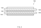
- FIG. 3 is a cross-sectional view illustrating a structure of a third radical unit of the secondary battery according to the present invention.
- a secondary battery according to the present invention may comprise a first radical unit 110, a second radical unit 120, and a third radical unit 130, each of which comprises an electrode and a separator.
- Each of the first to third radical units 110, 120, and 130 may have a structure in which a negative electrode 142, a separator 146, and positive electrodes 144 and 144' are alternately disposed.
- each of the first to third radical units may have a structure in which a negative electrode, a separator, and a positive electrode are alternately stacked.
- the first radical unit 110 may have a five-layered structure in which the negative electrode 142, the separator 146, the positive electrode 144, the separator 146, and the negative electrode 142 are alternately stacked.
- the second radical unit 120 may have a five-layered structure in which the positive electrode 144, the separator 146, the negative electrode 142, the separator 146, and the positive electrode 144 are alternatively disposed upward from a lower side.
- the third radical unit 130 may have a five-layered structure in which the positive electrode, the separator, the negative electrode, the separator, and the positive electrode are alternatively disposed upward from the lower side.
- one of the positive electrodes disposed on both ends of the third radical unit 130 may be a single-sided positive electrode 144'.
- the electrode may have a structure in which an electrode active material layer is applied on both surfaces of an electrode sheet.
- the single-sided positive electrode according to the present invention has a structure in which a positive electrode active material layer is applied to only one surface of the positive electrode sheet.
- a surface of both the surfaces of the positive electrode sheet of the single-sided positive electrode 144', on which the positive electrode active material layer is applied may be in contact with the separator 146.
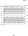
- an electrode assembly 10 may comprise a separation film 150 and the first to third radical units 110, 120, and 130, which are disposed on the separation film 150.
- the first to third radical units 110, 120, and 130 may have the same width.
- the first radical unit 110 when the electrode assembly 10 is unfolded, the first radical unit 110 may be disposed on one end of the separation film 150, and an empty space may be formed by the width of each of the first to third radical units in a direction of the other end of the separation film 150, which is opposite to the one end. Then, the two second radical units 120, the two first radical units 110, the two second radical units 120, the two first radical units 110, and the two third radical units 130 may be sequentially disposed. The single-sided positive electrode of the two third radical units 130 may be disposed to contact the separation film 150 (see FIG. 5 ).
- the electrode assembly 10 may have a structure in which the first to third radical units 110, 120, and 130 are disposed on the separation film 150, and then, the separation film 150 is folded.
- the above-described structure, in which the plurality of radical units comprising the electrodes are disposed on the separation film, and then, the separation film is folded will be referred to as a stacking & folding structure.
- the secondary battery according to the present invention may comprise an electrode assembly having a structure, in which the electrodes and the separators are alternately disposed and on which a curved surface is formed on each of top and bottom surfaces thereof, and a pouch type exterior which accommodates the electrode assembly, on which a curved surface having a curvature radius corresponding to that of the curved surface formed on each of the top and bottom surfaces of the electrode assembly is formed, and which comprises a cup having a concave shape.
- the curvature radius of each of the curved surfaces formed on the electrode assembly and the exterior may range of 70 mm to 150 mm. That is, the curvature radius of the curved surface of the secondary battery according to the present invention may range of 70 mm to 150 mm.
- the curvature radius of the secondary battery may be set in the range of 70 mm to 150 mm so as to be mounted on a head of the human, but if it is a secondary battery mounted on a VR device that is suitable for a general adult's head, the curvature radius of the secondary battery may be set to the range of 80 mm to 100 mm. Also, the secondary battery having the curvature radius of 70 mm may be mounted on a small-sized VR device that is worn by children or people having small heads, and the secondary battery having the curvature radius of 150 mm may be mounted on large-sized VR device that is worn by people having a large head.
- a method for manufacturing a secondary battery according to the present invention may comprise an electrode assembly preparation step of preparing an electrode assembly having a structure in which electrodes and separators are alternately disposed.
- a flat surface may be formed on each of top and bottom surfaces of the electrode assembly that is prepared in the electrode assembly preparation step.
- the electrode assembly prepared in the electrode assembly preparation step may comprise an electrode stack having (i) a lamination & stacking (L&S) structure in which a plurality of separate electrodes and a plurality of separate separators are alternately stacked in a thickness direction of the electrode assembly or (ii) a stacking & folding (S&F) structure in which a plurality of radical units comprising electrodes are disposed on a rectangular separation film, and the separation film is folded.
- L&S lamination & stacking
- S&F stacking & folding
- a pressure of pressing the radical unit to manufacture the radical unit may range of 180 kgf to 220 kgf, and a temperature of heating the radical unit may range of 45°C to 55°C.
- the electrode assembly prepared in the electrode assembly preparation step according to the present invention comprises the electrode stack having the S&F structure
- a pressure of pressing the separation film and the radical unit may range of 140 kgf to 160 kgf
- a heating temperature may range of 65°C to 75°C.
- the method for manufacturing the secondary battery according to the present invention may be performed for manufacturing a secondary battery having a curved surface having a relatively small curvature radius when compared to the secondary battery according to the related art.
- the curvature radius of the curved surface formed on the secondary battery manufactured by the method for manufacturing the secondary battery according to the present invention may range of 70 mm to 150 mm, and more specifically, range of 80 mm to 100 mm.
- the method for manufacturing the secondary battery according to the present invention may comprise a first pressing step of pressing top and bottom surfaces of the electrode assembly by using first pressing device, on which a curved surface is formed, to form a curved surface, which has a shape corresponding to that of the curved surface formed on the first pressing device, on each of the top and bottom surfaces of the electrode assembly.
- first pressing step according to the present invention since the curved surface is initially formed on each of the top and bottom surfaces of the electrode assembly, the first pressing step according to the present invention may be referred to as a curving process.
- a pressure of pressing the top and bottom surfaces of the electrode assembly may range of 600 kgf to 1,500 kgf
- a temperature of heating the top and bottom surfaces of the electrode assembly may range of 75°C to 85°C
- a time taken to press and heat the electrode assembly may range of 50 seconds to 110 seconds.
- the curved surface having the curvature radius within the range to be manufactured by the present invention may not be formed on the secondary battery.
- the pressure of pressing the top and bottom surfaces of the electrode assembly in the first pressing step exceeds 1,500 kgf, air permeability may be too large.
- the air permeability may refer to a time taken to allow air to pass through a certain component (e.g., the electrode assembly).
- the permeability of the electrode assembly may be measured to confirm ion permeability.
- that the air permeability of the electrode assembly is high may mean that it takes a long time to pass through the separator, i.e., that the ion permeability of the electrode assembly is low.
- the air permeability of the electrode assembly is too large, performance of the electrode assembly or the secondary battery may be deteriorated.
- a temperature of heating the top and bottom surfaces of the electrode assembly in the first pressing step may range of 950 kgf to 1,050 kgf. Alternatively, more preferably, a temperature of heating the top and bottom surfaces of the electrode assembly in the first pressing step may range of 900 kgf to 1,000 kgf. Also, more preferably, a time taken to pressing the top and bottom surfaces of the electrode assembly in the first pressing step may range of 55 seconds to 65 seconds. Alternatively, more preferably, a time taken to pressing the top and bottom surfaces of the electrode assembly in the first pressing step may range of 95 seconds to 105 seconds.
- the method of manufacturing the secondary battery according to the present invention may further comprise an accommodation step of accommodating the electrode assembly having the curved surface in a pouch type exterior (hereinafter, referred to as an "exterior") in which a cup having a concave shape is formed.
- a pouch type exterior hereinafter, referred to as an "exterior”
- the shape of the cup formed in the exterior may correspond to that of the electrode assembly on which the curved surface is formed by the first pressing step.
- the method for manufacturing the secondary battery according to the present invention may further comprise a cup formation step of forming a cup having a curved surface, which has a shape corresponding to that of the curved surface formed on each of the top and bottom surface of the electrode assembly in the first pressing step, in the exterior.
- the cup formation step is performed before the accommodation step.
- the method for manufacturing the secondary battery according to the present invention may further comprise a second pressing step of pressing the curved surface, which is formed on the electrode assembly in the first pressing step, and an outer surface of the exterior by using a second pressing device. That is, the second pressing step may be a step of pressing the curved surface formed on the secondary battery.
- the second pressing step may be performed after the accommodation step. That is, in the second pressing step, the electrode assembly may be accommodated in the cup formed in the exterior, and then, the outer surface of the exterior may be pressed to also press the curved surface formed on the electrode assembly accommodated in the exterior. Accordingly, according to the present invention, the shape of the curved surface of the electrode assembly formed in the first pressing step may be more firmly maintained by the second pressing step.
- a pressure of pressing the electrode assembly and the exterior i.e., the secondary battery
- a temperature of heating the top and bottom surfaces of the secondary battery may range 55°C to 65°C.
- the second pressing step may be performed by pressing the exterior, in which the electrode assembly is accommodated, through a first jig and a second jig after inserting the exterior, in which the electrode assembly is accommodated, between the first jig and the second jig, each of which has a curved surface. Therefore, the second pressing step may also be referred to as a jig formation process.
- FIG. 6 is a side view illustrating a state in which the curved surface is formed on the secondary battery after the second pressing step in the method for manufacturing the secondary battery according to the present invention, i.e., illustrates a case in which a curved surface C is formed on each of the top and bottom surfaces of the secondary battery 1 after the second pressing step.
- the method for manufacturing the secondary battery according to the present invention further comprises a surface leveling step of leveling the curved surface formed on the exterior, which is formed in the second pressing step.
- the surface leveling step may be performed after the second pressing step.
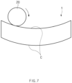
- FIG. 7 is a side view illustrating a state in which the surface leveling step is performed in the method for manufacturing the secondary battery according to an embodiment of the present invention.
- FIG. 7 illustrates a state in which a roller 20 having a cylindrical shape rotates on the curved surface C formed on the top surface of the secondary battery 1.
- the roller 20 having the cylindrical shape rotates on the curved surface C formed on the secondary battery 1 to improve the evenness of the curved surface formed on the secondary battery 1. More preferably, in the surface leveling step, when the roller 20 rotates on the curved surface formed on the secondary battery 1, the roller 20 having the cylindrical shape may not be slid on the curved surface C formed on the secondary battery 1. This may be understood as force of static friction acting between the roller and the curved surface formed on the secondary battery in the surface leveling step.
- the method for manufacturing the secondary battery according to the present invention further comprise a third pressing step of additionally pressing the curved surface formed on the electrode assembly and the curved surface formed on the exterior by using a third pressing device. That is, the third pressing step may be a step of pressing the curved surface formed on the secondary battery. The third pressing step is performed after the surface leveling step.
- the evenness of the curved surface formed on the exterior in the surface leveling step may be improved.
- the roller having the cylindrical shape presses the curved surface formed on the secondary battery, deformation may occur in the curvature radius of the curved surface formed on the secondary battery.
- the shape of the curved surface of the secondary battery, which is formed in the first pressing step and the second pressing step, may be more firmly maintained by the third pressing step.
- a pressure of pressing the top and bottom surfaces of the electrode assembly and the exterior may range of 300 kgf to 400 kgf
- a temperature of heating the top and bottom surfaces of the secondary battery may range of 75°C to 85°C
- a time taken to press and heat the top and bottom surfaces of the secondary battery may range of 8 seconds to 12 seconds.
- the third pressing step may be performed by heating and pressing the secondary battery through a hot press jig after inserting the secondary battery inside the hot press jig that is heated at a high temperature. Therefore, the third pressing step may be referred to as a hot press process.
- the curvature radius of the secondary battery after the third pressing step, i.e., the hot press process may range of 70 mm to 150 mm.
- a curved surface of an area for pressing an intermediate area of the electrode assembly and a curved surface of an area for pressing each of both ends of the electrode assembly may have curvature radii different from each other.
- the curvature radius of the curved surface of the area for pressing each of both the ends of the electrode assembly may be less than the curvature radius of the curved surface of the area for pressing the intermediate area of the electrode assembly.
- the electrode assembly on which the curved surface is formed by the pressing device may tend to be unfolded again as a time elapses. This is due to restoring force generated by adhesion between the electrode and the separator within the electrode assembly. This tendency is relatively large at an end of the curved surface formed on the electrode assembly.
- the reason in which the curved surfaces of the areas for pressing each of both the ends and the intermediate area have curvature radii different from each other is for offsetting the above-described tendency. That is, in the first pressing step, the curved surface, which is formed on each of both the ends, of the curved surface formed on the electrode assembly may have a relatively small curvature radius to reduce a deviation of the curvature radius on an entire area of the curved surface.
- the first radical unit has a structure in which a negative electrode, a separator, a positive electrode, a separator, and a negative electrode are sequentially stacked
- the second radical unit has a structure in which a positive electrode, a separator, a negative electrode, a separator, and a positive electrode are sequentially stacked
- the third radical unit has a structure in which a single-sided positive electrode, a separator, a negative electrode, a separator, and a positive electrode are sequentially stacked.
- a pressure applied to the electrode and the separator to allow the electrode and the separator to adhere to each other was 200 kgf, and a temperature of heating the electrode and the separator was 50°C.
- the first to third radical units were disposed on a top surface of the separation film.
- the first radical unit was disposed on one end of the separation film, and an empty space was formed by a width of each of the first to third radical units in a direction of the other end of the separation film.
- two second radical units, two first radical units, two second radical units, two first radical units, and two third radical units were sequentially disposed.
- single-sided positive electrodes of the two third radical units were disposed to contact the separation film.
- the separation film was folded to manufacture an electrode assembly.
- the electrode assembly was pressed using a first pressing device, on which a curved surface is formed, to form a curved surface on the electrode assembly (first pressing step).
- a pressing temperature was 80°C
- a pressing pressure was 600 kgf
- a pressing time was 60 seconds.
- the electrode assembly was accommodated in a sheet type exterior in which a cup having a shape corresponding to that of the electrode assembly, on which the curved surface is formed by the first pressing device, is formed to manufacture a secondary battery.
- the curved surface formed on the secondary battery was additionally pressed using a second pressing deice on which a curved surface is formed (jig formation process).
- a pressing temperature was 60°C
- a pressing pressure was 300 kgf.
- the curved surface formed on the secondary battery was additionally pressed using a third pressing deice on which a curved surface is formed (hot press process).
- a pressing temperature was 80°C
- a pressing pressure was 350 kgf
- a pressing time was 10 seconds.
- a secondary battery was manufactured in the same manner as in Embodiment 1, except that a pressing pressure when a first pressing device presses an electrode assembly is 900 kgf.
- a secondary battery was manufactured in the same manner as in Embodiment 1, except that a pressing pressure when a first pressing device presses an electrode assembly is 1,000 kgf.
- a secondary battery was manufactured in the same manner as in Embodiment 1, except that a pressing pressure when a first pressing device presses an electrode assembly is 1,500 kgf.
- a secondary battery was manufactured in the same manner as in Embodiment 1, except that a pressing time when a first pressing device presses an electrode assembly is 100 seconds.
- a curvature radius of the curved surface formed on each of the secondary batteries manufactured according to Embodiments 1 to 5 was measured. After photographing an image of the secondary battery by using a 3D measuring device from Keyence, three points of both end points and a middle point of the secondary battery was set to be measured. Then, a curvature radius was measured based on the three points.
- Air permeability of each of the secondary batteries prepared according to Embodiments 1 to 5 was measured.
- the results obtained by measuring the air permeability of each of the secondary batteries manufactured according to Embodiments 1 to 4 were illustrated in FIG. 10
- the results obtained by measuring the air permeability of each of the secondary batteries manufactured according to Embodiments 1 and 5 were illustrated in FIG. 11 .
- the air permeability was measured by calculating a time (seconds) that is taken to allow 100 ml of air to pass through the secondary battery.
- the air permeability of the secondary battery increases. That is, it is seen that as the pressure applied to the electrode assembly in the first pressing step increases, performance of the secondary battery is deteriorated. Particularly, it is seen that the air permeability rapidly increases when the pressure is 1,500 kgf (Embodiment 4) when compared to the case in which the pressure is 1,000 kgf (Embodiment 3).
- Embodiment 1 When comparing Embodiment 1 to Embodiment 5, it is seen that the curvature radius of the secondary battery in the case in which the pressing time in the first pressing step is 60 seconds (i.e., Embodiment 1) is significantly larger than the curvature radius of the secondary battery in the case in which the pressing time in the first pressing step is 100 seconds (i.e., Embodiment 5).
- the air permeability of the secondary battery in the case in which the pressing time in the first pressing step is 100 seconds is no significant difference from the air permeability of the secondary battery in the case in which the pressing time in the first pressing step is 60 seconds (i.e., Embodiment 1) (i.e., it is seen that the air permeability in both Embodiments 1 and 5 is about 250 seconds.
Landscapes
- Chemical & Material Sciences (AREA)
- Chemical Kinetics & Catalysis (AREA)
- Electrochemistry (AREA)
- General Chemical & Material Sciences (AREA)
- Engineering & Computer Science (AREA)
- Manufacturing & Machinery (AREA)
- Secondary Cells (AREA)
- Sealing Battery Cases Or Jackets (AREA)
- Battery Electrode And Active Subsutance (AREA)
Applications Claiming Priority (3)
| Application Number | Priority Date | Filing Date | Title |
|---|---|---|---|
| KR20190110276 | 2019-09-05 | ||
| KR1020200112507A KR20210029109A (ko) | 2019-09-05 | 2020-09-03 | 이차전지 및 그 이차전지의 제조방법 |
| PCT/KR2020/011916 WO2021045549A1 (ko) | 2019-09-05 | 2020-09-04 | 이차전지 및 그 이차전지의 제조방법 |
Publications (3)
| Publication Number | Publication Date |
|---|---|
| EP4009407A1 EP4009407A1 (en) | 2022-06-08 |
| EP4009407A4 EP4009407A4 (en) | 2023-02-22 |
| EP4009407B1 true EP4009407B1 (en) | 2024-04-03 |
Family
ID=74853380
Family Applications (1)
| Application Number | Title | Priority Date | Filing Date |
|---|---|---|---|
| EP20861343.0A Active EP4009407B1 (en) | 2019-09-05 | 2020-09-04 | Method for manufacturing a secondary battery |
Country Status (5)
| Country | Link |
|---|---|
| US (1) | US20220190310A1 (ko) |
| EP (1) | EP4009407B1 (ko) |
| JP (1) | JP7362189B2 (ko) |
| PL (1) | PL4009407T3 (ko) |
| WO (1) | WO2021045549A1 (ko) |
Family Cites Families (11)
| Publication number | Priority date | Publication date | Assignee | Title |
|---|---|---|---|---|
| WO2001082393A2 (en) * | 2000-04-25 | 2001-11-01 | Polystor Corporation | Custom geometry battery cells and methods and tools for their manufacture |
| JP2003187759A (ja) * | 2001-12-20 | 2003-07-04 | Mitsubishi Chemicals Corp | 二次電池及び二次電池の製造方法 |
| US10686209B2 (en) * | 2013-02-21 | 2020-06-16 | Samsung Sdi Co., Ltd. | Electrode assembly, battery cell including the electrode assembly, and method of preparing the battery cell |
| CN203312377U (zh) * | 2013-05-31 | 2013-11-27 | 深圳市格瑞普电池有限公司 | 铝塑膜壳体以及带该铝塑膜壳体的电池 |
| KR102221805B1 (ko) * | 2013-10-29 | 2021-03-03 | 삼성에스디아이 주식회사 | 커브드 이차 전지의 제조 방법 |
| KR101816946B1 (ko) * | 2013-10-30 | 2018-01-09 | 주식회사 엘지화학 | 셀 케이스, 그의 제조금형 및 제조방법, 전지셀 |
| JP2016039199A (ja) * | 2014-08-06 | 2016-03-22 | セイコーエプソン株式会社 | 太陽電池、電子機器および太陽電池の製造方法 |
| KR102221806B1 (ko) * | 2014-08-11 | 2021-03-02 | 삼성에스디아이 주식회사 | 커브드 이차 전지 및 이의 제조 방법 |
| KR101879911B1 (ko) * | 2015-03-27 | 2018-07-18 | 주식회사 엘지화학 | 휘어진 형상의 전지셀 제조방법 |
| KR20180056131A (ko) * | 2016-11-18 | 2018-05-28 | 에스케이이노베이션 주식회사 | 이차전지 압착용 롤러 |
| CN108878986B (zh) * | 2018-07-13 | 2022-10-11 | 广东天劲新能源科技股份有限公司 | 一种弧形锂离子电池制造装置及制造方法 |
-
2020
- 2020-09-04 EP EP20861343.0A patent/EP4009407B1/en active Active
- 2020-09-04 PL PL20861343.0T patent/PL4009407T3/pl unknown
- 2020-09-04 WO PCT/KR2020/011916 patent/WO2021045549A1/ko unknown
- 2020-09-04 JP JP2022512832A patent/JP7362189B2/ja active Active
-
2022
- 2022-03-04 US US17/686,576 patent/US20220190310A1/en active Pending
Also Published As
| Publication number | Publication date |
|---|---|
| JP2022546692A (ja) | 2022-11-07 |
| PL4009407T3 (pl) | 2024-05-13 |
| WO2021045549A1 (ko) | 2021-03-11 |
| JP7362189B2 (ja) | 2023-10-17 |
| CN114270585A (zh) | 2022-04-01 |
| US20220190310A1 (en) | 2022-06-16 |
| EP4009407A1 (en) | 2022-06-08 |
| EP4009407A4 (en) | 2023-02-22 |
Similar Documents
| Publication | Publication Date | Title |
|---|---|---|
| US11799122B2 (en) | Pouch for a secondary battery including a bridge and accommodation grooves | |
| CN104718655B (zh) | 电极组件的制造方法 | |
| EP3905417A1 (en) | Method for manufacturing electrode assembly, and electrode and secondary battery manufactured thereby | |
| KR20200023853A (ko) | 전극 조립체 제조장치 | |
| KR20230118779A (ko) | 전극 조립체 제조장치 | |
| EP1455400A2 (en) | Film covered battery | |
| US11749841B2 (en) | Method for manufacturing electrode assembly and method for manufacturing secondary battery | |
| EP4009407B1 (en) | Method for manufacturing a secondary battery | |
| US11508970B2 (en) | Battery and battery manufacturing method | |
| US20200194763A1 (en) | Electrode assembly and method for manufacturing the same | |
| KR20210029109A (ko) | 이차전지 및 그 이차전지의 제조방법 | |
| CN114270585B (zh) | 二次电池及制造该二次电池的方法 | |
| US11621434B2 (en) | Method for manufacturing electrode assembly | |
| CN218101372U (zh) | 叠片电池的叠片设备及电芯 | |
| US20230223576A1 (en) | Plasma Generator for Secondary Battery and Lamination System Comprising the Same | |
| US20230369630A1 (en) | Unit Cell Preparation Apparatus and Method | |
| EP3497736B1 (en) | Battery with perforated continuous separator | |
| EP3584868B1 (en) | Manufacturing method of secondary battery | |
| WO2024011703A1 (zh) | 辊压装置、复合极片、电池单体及用电装置 | |
| KR20230096885A (ko) | 전극 조립체 및 이의 제조 방법 | |
| JP2024024027A (ja) | 二次電池、その二次電池の製造方法、及びその二次電池を含む電池パック | |
| US20190273263A1 (en) | Electrode Assembly, Secondary Battery Including the Electrode Assembly, and Method for Manufacturing the Electrode Assembly | |
| KR20230148633A (ko) | 전극 조립체의 제조 방법 및 전극 조립체의 제조장치 | |
| KR20220112515A (ko) | 선압착 및 면압착을 포함하는 전극조립체 제조방법, 이를 이용하여 제조된 전극조립체 | |
| JP2024503884A (ja) | 二次電池製造装置及びそれを用いる二次電池製造方法 |
Legal Events
| Date | Code | Title | Description |
|---|---|---|---|
| STAA | Information on the status of an ep patent application or granted ep patent |
Free format text: STATUS: THE INTERNATIONAL PUBLICATION HAS BEEN MADE |
|
| PUAI | Public reference made under article 153(3) epc to a published international application that has entered the european phase |
Free format text: ORIGINAL CODE: 0009012 |
|
| STAA | Information on the status of an ep patent application or granted ep patent |
Free format text: STATUS: REQUEST FOR EXAMINATION WAS MADE |
|
| 17P | Request for examination filed |
Effective date: 20220302 |
|
| AK | Designated contracting states |
Kind code of ref document: A1 Designated state(s): AL AT BE BG CH CY CZ DE DK EE ES FI FR GB GR HR HU IE IS IT LI LT LU LV MC MK MT NL NO PL PT RO RS SE SI SK SM TR |
|
| DAV | Request for validation of the european patent (deleted) | ||
| DAX | Request for extension of the european patent (deleted) | ||
| A4 | Supplementary search report drawn up and despatched |
Effective date: 20230119 |
|
| RIC1 | Information provided on ipc code assigned before grant |
Ipc: H01M 50/107 20210101ALI20230113BHEP Ipc: H01M 50/105 20210101ALI20230113BHEP Ipc: H01M 10/04 20060101AFI20230113BHEP |
|
| STAA | Information on the status of an ep patent application or granted ep patent |
Free format text: STATUS: EXAMINATION IS IN PROGRESS |
|
| 17Q | First examination report despatched |
Effective date: 20230818 |
|
| GRAP | Despatch of communication of intention to grant a patent |
Free format text: ORIGINAL CODE: EPIDOSNIGR1 |
|
| STAA | Information on the status of an ep patent application or granted ep patent |
Free format text: STATUS: GRANT OF PATENT IS INTENDED |
|
| INTG | Intention to grant announced |
Effective date: 20240108 |
|
| GRAS | Grant fee paid |
Free format text: ORIGINAL CODE: EPIDOSNIGR3 |
|
| GRAA | (expected) grant |
Free format text: ORIGINAL CODE: 0009210 |
|
| STAA | Information on the status of an ep patent application or granted ep patent |
Free format text: STATUS: THE PATENT HAS BEEN GRANTED |
|
| P01 | Opt-out of the competence of the unified patent court (upc) registered |
Effective date: 20240202 |
|
| AK | Designated contracting states |
Kind code of ref document: B1 Designated state(s): AL AT BE BG CH CY CZ DE DK EE ES FI FR GB GR HR HU IE IS IT LI LT LU LV MC MK MT NL NO PL PT RO RS SE SI SK SM TR |
|
| REG | Reference to a national code |
Ref country code: CH Ref legal event code: EP |
|
| REG | Reference to a national code |
Ref country code: IE Ref legal event code: FG4D |
|
| REG | Reference to a national code |
Ref country code: DE Ref legal event code: R096 Ref document number: 602020028519 Country of ref document: DE |
|
| REG | Reference to a national code |
Ref country code: SE Ref legal event code: TRGR |
|
| REG | Reference to a national code |
Ref country code: NL Ref legal event code: FP |