EP4008939B1 - Vakuumbegrenzungsventil - Google Patents
Vakuumbegrenzungsventil Download PDFInfo
- Publication number
- EP4008939B1 EP4008939B1 EP21211077.9A EP21211077A EP4008939B1 EP 4008939 B1 EP4008939 B1 EP 4008939B1 EP 21211077 A EP21211077 A EP 21211077A EP 4008939 B1 EP4008939 B1 EP 4008939B1
- Authority
- EP
- European Patent Office
- Prior art keywords
- valve
- holding element
- cover
- cleaning device
- holding
- Prior art date
- Legal status (The legal status is an assumption and is not a legal conclusion. Google has not performed a legal analysis and makes no representation as to the accuracy of the status listed.)
- Active
Links
Images

Classifications
-
- F—MECHANICAL ENGINEERING; LIGHTING; HEATING; WEAPONS; BLASTING
- F16—ENGINEERING ELEMENTS AND UNITS; GENERAL MEASURES FOR PRODUCING AND MAINTAINING EFFECTIVE FUNCTIONING OF MACHINES OR INSTALLATIONS; THERMAL INSULATION IN GENERAL
- F16K—VALVES; TAPS; COCKS; ACTUATING-FLOATS; DEVICES FOR VENTING OR AERATING
- F16K15/00—Check valves
- F16K15/02—Check valves with guided rigid valve members
- F16K15/06—Check valves with guided rigid valve members with guided stems
- F16K15/063—Check valves with guided rigid valve members with guided stems the valve being loaded by a spring
-
- A—HUMAN NECESSITIES
- A47—FURNITURE; DOMESTIC ARTICLES OR APPLIANCES; COFFEE MILLS; SPICE MILLS; SUCTION CLEANERS IN GENERAL
- A47L—DOMESTIC WASHING OR CLEANING; SUCTION CLEANERS IN GENERAL
- A47L9/00—Details or accessories of suction cleaners, e.g. mechanical means for controlling the suction or for effecting pulsating action; Storing devices specially adapted to suction cleaners or parts thereof; Carrying-vehicles specially adapted for suction cleaners
- A47L9/0072—Mechanical means for controlling the suction or for effecting pulsating action
-
- A—HUMAN NECESSITIES
- A47—FURNITURE; DOMESTIC ARTICLES OR APPLIANCES; COFFEE MILLS; SPICE MILLS; SUCTION CLEANERS IN GENERAL
- A47L—DOMESTIC WASHING OR CLEANING; SUCTION CLEANERS IN GENERAL
- A47L9/00—Details or accessories of suction cleaners, e.g. mechanical means for controlling the suction or for effecting pulsating action; Storing devices specially adapted to suction cleaners or parts thereof; Carrying-vehicles specially adapted for suction cleaners
- A47L9/28—Installation of the electric equipment, e.g. adaptation or attachment to the suction cleaner; Controlling suction cleaners by electric means
- A47L9/2889—Safety or protection devices or systems, e.g. for prevention of motor over-heating or for protection of the user
-
- F—MECHANICAL ENGINEERING; LIGHTING; HEATING; WEAPONS; BLASTING
- F16—ENGINEERING ELEMENTS AND UNITS; GENERAL MEASURES FOR PRODUCING AND MAINTAINING EFFECTIVE FUNCTIONING OF MACHINES OR INSTALLATIONS; THERMAL INSULATION IN GENERAL
- F16K—VALVES; TAPS; COCKS; ACTUATING-FLOATS; DEVICES FOR VENTING OR AERATING
- F16K31/00—Actuating devices; Operating means; Releasing devices
- F16K31/003—Actuating devices; Operating means; Releasing devices operated without a stable intermediate position, e.g. with snap action
-
- F—MECHANICAL ENGINEERING; LIGHTING; HEATING; WEAPONS; BLASTING
- F16—ENGINEERING ELEMENTS AND UNITS; GENERAL MEASURES FOR PRODUCING AND MAINTAINING EFFECTIVE FUNCTIONING OF MACHINES OR INSTALLATIONS; THERMAL INSULATION IN GENERAL
- F16K—VALVES; TAPS; COCKS; ACTUATING-FLOATS; DEVICES FOR VENTING OR AERATING
- F16K31/00—Actuating devices; Operating means; Releasing devices
- F16K31/02—Actuating devices; Operating means; Releasing devices electric; magnetic
- F16K31/06—Actuating devices; Operating means; Releasing devices electric; magnetic using a magnet, e.g. diaphragm valves, cutting off by means of a liquid
- F16K31/08—Actuating devices; Operating means; Releasing devices electric; magnetic using a magnet, e.g. diaphragm valves, cutting off by means of a liquid using a permanent magnet
- F16K31/084—Actuating devices; Operating means; Releasing devices electric; magnetic using a magnet, e.g. diaphragm valves, cutting off by means of a liquid using a permanent magnet the magnet being used only as a holding element to maintain the valve in a specific position, e.g. check valves
Definitions
- the invention relates to a cleaning device with a vacuum limiting valve, which is used in particular as a secondary air valve of a suction cleaning device.
- a vacuum relief valve is usually used in compressors, especially for extracting air. This is particularly the case when forced-feed compressors, such as side channel compressors, are used. Such vacuum relief valves are also referred to as bypass air valves.
- the vacuum relief valve prevents overloading when driving the compressor, thereby avoiding damage.
- the valve opens as soon as the flow resistance in the air flow line (suction line) increases or is blocked and a significant pressure difference forms in the compressor.
- Conventional valves have a mechanical spring for this purpose.
- the linear spring force the valve opens further and further the higher the pressure difference in the compressor is in order to compensate for the lack of pressure or the lack of air volume flow.
- the spring closes the valve automatically as soon as the differential pressure falls below a certain value.
- the problem here is that due to the linear spring force, the valve already begins to open, even if critical overloading of the drive is not yet expected. Pressure and flow losses occur as a result of the early slight opening of the valve.
- EP 0 955 003 A1 shows a known cleaning device with a vacuum relief valve.
- the vacuum limiting valve should not be closed primarily by an elastic element, such as a spring, but rather a permanent magnet should be used.
- a permanent magnet By using the permanent magnet to close the vacuum limiting valve, its opening movement is no longer dependent on the linear spring force, but can be opened completely very abruptly and essentially immediately when a predetermined pressure difference is reached.
- the vacuum limiting valve presented here comprises a base with a valve opening.
- a valve seat is formed on the inside of the valve opening.
- this valve seat surrounds the valve opening in a ring shape.
- the seal is preferably elastic to compensate for tolerances.
- the base is preferably plate-shaped and is integrated into a compressor on the suction side or installed in the suction line that leads to the compressor.
- the valve opening in the base leads from an inside of the vacuum relief valve to an outside of the vacuum relief valve. When the vacuum relief valve is used, the inside of the base is subjected to the negative pressure.
- the valve opening preferably leads to the atmosphere.
- the vacuum limiting valve also includes a valve cover that seals against the valve seat when the valve is closed.
- the valve cover rests against the inside of the valve seat.
- the valve cover can be moved inwards to release the valve opening and thus open the vacuum limiting valve.
- a seal can also be used on the corresponding surface of the valve cover.
- valve cover moves inwards and away from the valve seat when the differential pressure is sufficiently high (compared to the atmosphere). This opens the vacuum relief valve.
- the vacuum limiting valve comprises a locking device.
- This locking device is made up of two holding elements that magnetically attract each other.
- the first holding element is arranged in a fixed position.
- the second holding element is connected to the valve cover. At least one of the two holding elements is a permanent magnet.
- the other holding element can also be a permanent magnet or is made of ferromagnetic material. It is particularly preferred that the second holding element is a permanent magnet and the first holding element is a steel plate.
- the vacuum limiting valve When closed, the vacuum limiting valve is held shut by the two retaining elements that attract each other. In particular, the two retaining elements rest against each other. The valve cover is pulled inwards by a sufficiently high negative pressure on the inside of the vacuum limiting valve. The second retaining element also moves with the valve cover and thus moves away from the first retaining element.
- the vacuum limiting valve comprises an elastic element which urges the valve cover towards its closed position.
- the elastic element is in particular a spring, for example a spiral-shaped compression spring.
- the holding force of the vacuum limiting valve is generated primarily by the magnetically attracted holding elements.
- the elastic element is only intended for fine adjustment of the opening differential pressure or for secure closing.
- a magnetic force Fm acts on the valve cover, defined in the closed position.
- a spring force Ff acts on the valve cover through the elastic element.
- This force is referred to here as "spring force”, but can also be generated by an elastic element other than a spring. In particular, the spring force is generated in the closed position of the valve cover by pre-tensioning the elastic element accordingly.
- the magnetic force Fm in the closed position is greater than the spring force Ff.
- the magnetic force Fm is at least twice the spring force Ff, more preferably the magnetic force Fm is at least five times the spring force Ff, particularly preferably the magnetic force Fm is at least ten times the spring force Ff.
- the vacuum limiting valve is "controllable". This means that the vacuum limiting valve cannot be controlled electrically, hydraulically, pneumatically or in any other way and can therefore be opened or closed.
- the vacuum limiting valve is only opened or closed depending on the negative pressure on the inside of the vacuum limiting valve.
- the locking device and the entire vacuum limiting valve do not have an electromagnet.
- valve cover is connected to a valve rod.
- the second holding element in particular the permanent magnet, is preferably located on the valve rod.
- the valve rod is connected to the valve cover at its inner end and extends outwards through the valve opening.
- the second holding element is arranged in particular at the outer end of the valve rod.
- the elastic element is preferably designed as a compression spring and sits on the valve rod.
- a nut is mounted on the valve rod. is screwed on, against which the elastic element rests. The spring force can be adjusted using this nut.
- the base comprises a support region that extends across the valve opening.
- the valve rod can run through this support region and can be guided in a linearly movable manner in the support region.
- the elastic element in particular designed as a compression spring, rests against this support region.
- the support region is preferably designed such that it covers as little area of the valve opening as possible.
- valve rod extends parallel to a valve axis.
- the valve cover is opened along this valve axis, so that the opening direction of the valve cover is aligned parallel to the valve axis and thus parallel to the valve rod.
- the second holding element can be moved away from the first holding element parallel to the opening direction in order to open the valve cover.
- the first holding element in particular designed as a steel plate, is fastened to the base by means of a fastening device.
- the fastening device has one or more feet that extend to the side of the valve rod.
- the fastening device encompasses the valve rod and the first holding element can be arranged opposite the outer end of the valve rod.
- the fastening device is particularly preferably manufactured in one piece together with the first holding element, designed as a steel plate.
- valve rod and/or the second holding element is/are guided in a linearly movable manner on a guide of the fastening device.
- the valve rod is preferably guided not only in the area of the base, but also at the opposite end in the area of the fastening device. Since the second holding element is located here, this holding element can also be guided instead of the valve rod.
- the invention provides that the first holding element is movably arranged on the fastening device so that an overlap of the first holding element with the second holding element is adjustable, whereby the magnetic force Fm can be adjusted.
- the identically constructed vacuum limiting valve can be used for different compressors, with the required magnetic force Fm being adjusted during assembly.
- the first holding element is preferably movable horizontally to the opening direction of the valve.
- the defined relation of the magnetic force Fm to the spring force Ff preferably refers to the maximum adjustable magnetic force Fm and the maximum adjustable spring force Ff, provided that the spring force is also adjustable.
- the fastening device preferably comprises a base body, which is connected in particular to the base and surrounds the valve rod.
- a cover of the fastening device is preferably rotatably mounted on the base body, wherein the first holding element is arranged between the base body and the cover and can be moved relative to the base body by rotating the cover.
- the cover and/or the base body is/are preferably made of non-magnetizable material, in particular plastic.
- the first holding element is guided on the base body and is moved via a slotted guide formed between the cover and the first holding element, in particular in a plane horizontal to the opening direction.
- the invention further comprises a compressor.
- the compressor is designed in particular as a side channel compressor.
- the compressor is designed to suck in gas, in particular air.
- the compressor comprises the vacuum limiting valve described here.
- the invention further comprises a cleaning device with a compressor.
- the compressor is again preferably a side channel compressor.
- the cleaning device is designed to suck in air, possibly including impurities, and comprises a vacuum limiting valve described here in the suction line or directly on the suction side in the compressor.
- the vacuum limiting valve is arranged here as a secondary air valve.
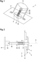
- Fig. 1 and 2 show that a vacuum limiting valve 1 not according to the invention with a base 2.
- An inner side 3 and an outer side 4 are defined on the base 2.
- a valve opening 5 is provided in the base 2, which connects the inner side 3, which is usually subjected to internal pressure, with the outside side 4 on the atmospheric side.
- valve seat 7 On the inside of the valve opening 5 there is a valve seat 7, in the example shown formed by a seal 6.
- a valve cover 8 rests on the valve seat 7 and can be opened inwards along a valve axis 9.
- the valve cover 8 is connected to a valve rod 10.
- the valve rod 10 extends outwards along the valve axis 9.
- the vacuum limiting valve 1 has a magnetic locking device.
- This comprises a first holding element 11, which is fixed in place (or according to Fig.4 movable) and is implemented as a steel plate in the embodiment shown.
- the first holding element 11 interacts with a second holding element 12.
- the second holding element 12 is designed as a permanent magnet and is located on the outside end of the valve rod 10.
- the vacuum limiting valve 1 is closed. Accordingly, the valve cover 8 rests on the valve seat 7 and the second holding element 12 rests on the first holding element 11.
- Fig.1 clarifies in the schematic representation a fastening device 13 which is fastened to the outside of the base 2 and is used to position the first holding element 11 opposite the outer end of the valve rod 10 or opposite the second holding element 12.
- this fastening device 13 has two feet which extend from the base 2. These feet are formed in one piece with the first holding element 11 which is designed as a steel plate.
- Fig.1 further shows that a support region 14 extends across the valve opening 5, which can be an integral part of the base 2. The valve rod 10 runs through the support region 14 and can be guided in a linearly movable manner in the support region 14.
- the Fig. 1 and 2 an elastic element 15, here designed as a spiral compression spring on the valve rod 10.
- the elastic element 15 can be prestressed by means of a nut 16, accordingly the elastic element 15 is supported on the one hand against the nut 16 and on the other hand against the support area 14.
- a stop 17 can be used to limit an opening movement of the valve cover 8 or the valve rod 10.
- this stop 17 is formed by a sleeve that is placed on the valve rod 10. When the vacuum limiting valve 1 is opened sufficiently large, the nut 16 strikes the sleeve-shaped stop 17.
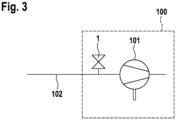
- Fig.3 shows purely schematically a cleaning device 100 with a compressor 101, in particular designed as a side channel compressor.
- the cleaning device 100 serves to extract air, possibly including impurities. This takes place via a corresponding suction line 102.
- the vacuum limiting valve 1 is arranged as a secondary air valve according to one of the two embodiments.
- Fig.4 shows the vacuum limiting valve 1 according to the second embodiment of the invention in section. Identical or functionally identical components are provided with the same reference numerals in both embodiments.
- the two vacuum limiting valves 1 according to the two embodiments are functionally identical; except for the following differences:
- the second holding element 12 is guided in a linearly movable manner on a guide 20 of the fastening device 13.
- the valve rod 10 is guided not only at the support area 14, but also at the opposite end in the area of the fastening device 13. Since the second holding element 12 is located here, this holding element 12 is guided instead of the valve rod 10.
- the first holding element 11 is movably arranged on the fastening device 13, so that an overlap of the first holding element 11 with the second holding element 12 is adjustable, whereby the magnetic force Fm can be adjusted.
- the first holding element 11 can be moved perpendicular to the valve axis 9.
- the fastening device 13 comprises a base body 18, which is connected to the base 2 and surrounds the valve rod 10.
- a cover 19 of the fastening device 13 is rotatably mounted on the base body 18, wherein the first holding element 11 is arranged between the base body 18 and the cover 19 and by rotating the cover 19 relative to the Base body 18 is movable.
- the first holding element 11 is guided on the base body 18 and is moved, for example, via a guide rail formed between the cover 19 and the first holding element 11.
- the base body 18 has a groove 21.
- the cover 19 is secured against removal by means of a locking element 22 which projects into this groove and is simultaneously rotatable, whereby the angle of rotation of the cover 19 and thus the set magnetic force can be fixed by further screwing in the locking element 22.
Landscapes
- Engineering & Computer Science (AREA)
- General Engineering & Computer Science (AREA)
- Mechanical Engineering (AREA)
- Safety Valves (AREA)
- Compressors, Vaccum Pumps And Other Relevant Systems (AREA)
Description
- Die Erfindung betrifft eine Reinigungsvorrichtung mit einem Vakuumbegrenzungsventil, das insbesondere als Nebenluftventil einer saugenden Reinigungsvorrichtung zur Anwendung kommt.
- Bei Verdichtern, insbesondere zum Absaugen von Luft, wird im Regelfall ein Vakuumbegrenzungsventil eingesetzt. Insbesondere ist dies der Fall, wenn zwangsfördernde Verdichter, wie beispielsweise Seitenkanalverdichter, verwendet werden. Solche Vakuumbegrenzungsventile sind auch als Nebenluftventile zu bezeichnen.
- Das Vakuumbegrenzungsventil verhindert, dass eine Überlastung beim Antrieb des Verdichters eintritt, wodurch Schäden vermieden werden. In der Absaugtechnik öffnet sich das Ventil, sobald der Strömungswiderstand in der Luftströmungsleitung (Saugleitung) ansteigt oder blockiert wird und sich eine erhebliche Druckdifferenz im Verdichter bildet. Herkömmliche Ventile weisen hierzu eine mechanische Feder auf. Infolge der linearen Federkraft öffnet sich das Ventil immer weiter, je höher die entstehende Druckdifferenz im Verdichter ist, um den fehlenden Druck bzw. den fehlenden Luftvolumenstrom auszugleichen. Die Feder schließt das Ventil selbstständig, sobald der Differenzdruck unter einen bestimmten Wert abfällt. Problematisch ist dabei, dass aufgrund der linearen Federkraft das Ventil sich bereits zu öffnen beginnt, auch wenn noch keine kritische Überlastung des Antriebs zu erwarten ist. Durch die frühzeitige leichte Öffnung des Ventils treten Druck- und Strömungsverluste auf.
EP 0 955 003 A1 zeigt eine bekannte Reinigungsvorrichtung mit einem Vakuumbegrenzungsventil. - Es ist Aufgabe vorliegender Erfindung, ein Vakuumbegrenzungsventil einer Reinigungsvorrichtung anzugeben, das ab einem bestimmten Unterdruck zuverlässig und möglichst vollständig öffnet.
- Die Lösung dieser Aufgabe erfolgt durch die Merkmale des unabhängigen Anspruchs 1. Die abhängigen Ansprüche haben vorteilhafte Ausgestaltungen der Erfindung zum Gegenstand.
- Im Rahmen der Erfindung wurde erkannt, dass das Vakuumbegrenzungsventil nicht primär durch ein elastisches Element, beispielsweise eine Feder, zuzuhalten ist, sondern ein Permanentmagnet eingesetzt werden sollte. Durch die Verwendung des Permanentmagneten zum Zuhalten des Vakuumbegrenzungsventils ist dessen Öffnungsbewegung nicht mehr von der linearen Federkraft abhängig, sondern kann ab einer vorbestimmten Druckdifferenz sehr abrupt und im Wesentlichen unmittelbar vollständig geöffnet werden.
- Das hier vorgestellte Vakuumbegrenzungsventil umfasst eine Basis mit einer Ventilöffnung. Innenseitig an der Ventilöffnung ist ein Ventilsitz ausgebildet. Insbesondere umgibt dieser Ventilsitz ringförmig die Ventilöffnung. Besonders bevorzugt befindet sich am Ventilsitz eine Dichtung; insbesondere eine ringförmige Dichtung. Zum Toleranzausgleich ist die Dichtung vorzugsweise elastisch.
- Die Basis ist vorzugsweise plattenförmig ausgebildet und wird saugseitig in einen Verdichter integriert oder in die Saugleitung eingebaut, die zum Verdichter führt. Die Ventilöffnung in der Basis führt von einer Innenseite des Vakuumbegrenzungsventils zu einer Außenseite des Vakuumbegrenzungsventils. Bei Benutzung des Vakuumbegrenzungsventils ist die Innenseite der Basis mit dem Unterdruck beaufschlagt. Die Ventilöffnung führt vorzugsweise zur Atmosphäre.
- Des Weiteren umfasst das Vakuumbegrenzungsventil einen Ventildeckel, der im geschlossenen Zustand des Ventils dichtend am Ventilsitz anliegt. Insbesondere liegt der Ventildeckel innen am Ventilsitz an. Der Ventildeckel ist nach innen zur Freigabe der Ventilöffnung und somit zum Öffnen des Vakuumbegrenzungsventils bewegbar. Zusätzlich oder alternativ zu der o.g. Dichtung am Ventilsitz kann auch an der entsprechenden Fläche des Ventildeckels eine Dichtung verwendet werden.
- Durch den Unterdruck in der Saugleitung bzw. im Verdichter wird bei entsprechend großem Differenzdruck (gegenüber der Atmosphäre) der Ventildeckel nach innen und somit vom Ventilsitz wegbewegt. Dadurch öffnet sich das Vakuumbegrenzungsventil.
- Das Vakuumbegrenzungsventil umfasst eine Zuhaltevorrichtung. Diese Zuhaltevorrichtung setzt sich aus zwei Halteelementen zusammen, die sich gegenseitig magnetisch anziehen. Das erste Halteelement ist ortsfest angeordnet. Das zweite Halteelement ist mit dem Ventildeckel verbunden. Zumindest eines der beiden Halteelemente ist ein Permanentmagnet. Das jeweils andere Halteelement kann ebenfalls ein Permanentmagnet sein oder ist aus ferromagnetischem Material gefertigt. Besonders bevorzugt ist vorgesehen, dass das zweite Halteelement ein Permanentmagnet ist und das erste Halteelement eine Stahlplatte ist.
- Im geschlossenen Zustand wird das Vakuumbegrenzungsventil durch die beiden sich anziehenden Halteelemente zugehalten. Insbesondere liegen dabei die beiden Halteelemente aneinander an. Durch entsprechend großen Unterdruck an der Innenseite des Vakuumbegrenzungsventils wird der Ventildeckel nach innen gezogen. Mit dem Ventildeckel bewegt sich auch das zweite Halteelement und entfernt sich somit vom ersten Halteelement.
- Durch die Entfernung der beiden Halteelemente voneinander nimmt die magnetische Anziehungskraft schlagartig ab, so dass sich das Vakuumbegrenzungsventil vollständig öffnet.
- Das Vakuumbegrenzungsventil umfasst erfindungsgemäß ein elastisches Element, das den Ventildeckel in Richtung seiner Schließlage beaufschlagt. Das elastische Element ist insbesondere eine Feder, beispielsweise eine spiralförmige Druckfeder.
- Es ist insbesondere vorgesehen, dass die zuhaltende Kraft des Vakuumbegrenzungsventils in erster Linie durch die sich magnetisch anziehenden Halteelemente erzeugt werden. Lediglich zur Feineinstellung des Öffnungsdifferenzdrucks bzw. zum sicheren Schließen ist das elastische Element vorgesehen.
- Durch die sich anziehenden Halteelemente wirkt, definiert in Schließlage, eine Magnetkraft Fm auf den Ventildeckel. Gleichzeitig wirkt durch das elastische Element eine Federkraft Ff auf den Ventildeckel. Diese Kraft wird hier als "Federkraft" bezeichnet, kann jedoch auch von einem anderen elastischen Element als einer Feder erzeugt werden. Insbesondere wird die Federkraft in Schließlage des Ventildeckels erzeugt, indem das elastische Element entsprechend vorgespannt ist.
- Erfindungsgemäß ist vorgesehen, dass die Magnetkraft Fm in Schließlage größer ist als die Federkraft Ff. Insbesondere beträgt die Magnetkraft Fm zumindest das 2-fache der Federkraft Ff, weiter vorzugsweise beträgt die Magnetkraft Fm zumindest das 5-fache der Federkraft Ff, besonders vorzugsweise beträgt die Magnetkraft Fm zumindest das 10-fache der Federkraft Ff.
- Es ist insbesondere vorgesehen, dass das Vakuumbegrenzungsventil "ansteuerlos" ist. Dies bedeutet, dass das Vakuumbegrenzungsventil weder elektrisch noch hydraulisch noch pneumatisch oder auf sonstige Weise ansteuerbar ist und somit geöffnet oder geschlossen werden kann. Lediglich in Abhängigkeit des an der Innenseite des Vakuumbegrenzungsventils anliegenden Unterdrucks ergibt sich eine Öffnung bzw. Schließung des Vakuumbegrenzungsventils. Insbesondere weist die Zuhaltevorrichtung sowie das gesamte Vakuumbegrenzungsventil keinen Elektromagneten auf.
- Es ist bevorzugt vorgesehen, dass der Ventildeckel mit einer Ventilstange verbunden ist. Das zweite Halteelement, also insbesondere der Permanentmagnet, befindet sich vorzugsweise an der Ventilstange. Insbesondere ist die Ventilstange mit ihrem innenliegenden Ende mit dem Ventildeckel verbunden und erstreckt sich durch die Ventilöffnung nach außen. Das zweite Halteelement ist insbesondere an dem außenliegenden Ende der Ventilstange angeordnet. Das elastische Element ist vorzugsweise als Druckfeder ausgebildet und sitzt auf der Ventilstange. Insbesondere ist vorgesehen, dass auf der Ventilstange eine Mutter aufgeschraubt ist, gegen die sich das elastische Element abstützt. Mittels dieser Mutter kann die Federkraft eingestellt werden.
- Des Weiteren ist bevorzugt vorgesehen, dass die Basis einen Stützbereich umfasst, der sich quer über die Ventilöffnung erstreckt. Die Ventilstange kann durch diesen Stützbereich hindurchverlaufen und kann in dem Stützbereich linear beweglich geführt sein. Alternativ oder zusätzlich ist vorgesehen, dass das elastische Element, insbesondere ausgebildet als Druckfeder, gegen diesen Stützbereich anliegt. Der Stützbereich ist vorzugsweise so ausgebildet, dass er möglichst wenig Fläche der Ventilöffnung verdeckt.
- Des Weiteren ist bevorzugt vorgesehen, dass sich die Ventilstange parallel zu einer Ventilachse erstreckt. Entlang dieser Ventilachse erfolgt die Öffnung des Ventildeckels, so dass die Öffnungsrichtung des Ventildeckels parallel zur Ventilachse und somit parallel zur Ventilstange ausgerichtet ist. Insbesondere ist das zweite Halteelement zum Öffnen des Ventildeckels parallel zu der Öffnungsrichtung vom ersten Halteelement weg bewegbar.
- Das erste Halteelement, insbesondere ausgebildet als Stahlplatte, ist erfindungsgemäß mittels einer Befestigungsvorrichtung an der Basis befestigt. Insbesondere weist die Befestigungsvorrichtung einen oder mehrere Füße auf, die sich seitlich der Ventilstange erstrecken. Dadurch umgreift die Befestigungsvorrichtung die Ventilstange und das erste Halteelement kann gegenüber dem außenliegenden Ende der Ventilstange angeordnet werden. Besonders bevorzugt ist die Befestigungsvorrichtung zusammen mit dem ersten Halteelement, ausgebildet als Stahlplatte, einstückig gefertigt.
- Vorzugsweise ist/sind die Ventilstange und/oder das zweite Halteelement an einer Führung der Befestigungsvorrichtung linearbeweglich geführt. Dadurch erfolgt vorzugsweise nicht nur im Bereich der Basis eine Führung der Ventilstange, sondern auch am gegenüberliegenden Ende im Bereich der Befestigungsvorrichtung. Da sich hier das zweite Halteelement befindet, kann anstatt der Ventilstange auch dieses Halteelement geführt werden.
- Anstatt einer festen bzw. einstückigen Ausgestaltung des ersten Halteelements mit der Befestigungsvorrichtung, ist erfindungsgemäß vorgesehen, dass das erste Halteelement bewegbar an der Befestigungsvorrichtung angeordnet ist, sodass eine Überlappung des ersten Halteelements mit dem zweiten Halteelement einstellbar ist, wodurch sich die Magnetkraft Fm einstellen lässt. Dadurch kann das baugleiche Vakuumbegrenzungsventil für verschiedene Verdichter verwendet werden, wobei bei der Montage die benötigte Magnetkraft Fm eingestellt wird.
- Zur Veränderung der Überlappung ist das erste Halteelement vorzugsweise waagerecht zur Öffnungsrichtung des Ventils bewegbar.
- Die definierte Relation der Magnetkraft Fm zur Federkraft Ff bezieht sich vorzugsweise auf die maximal einstellbare Magnetkraft Fm und die maximal einstellbare Federkraft Ff, sofern auch die Federkraft einstellbar ist.
- Vorzugsweise umfasst die Befestigungsvorrichtung einen Grundkörper, der insbesondere mit der Basis verbunden ist und die Ventilstange umgreift. Auf dem Grundkörper ist vorzugsweise ein Deckel der Befestigungsvorrichtung drehbar gelagert, wobei das erste Halteelement zwischen Grundkörper und Deckel angeordnet ist und durch Drehen des Deckels relativ zum Grundkörper bewegbar ist. Der Deckel und/oder der Grundkörper ist/sind vorzugsweise aus nicht-magnetisierbarem Material, insbesondere Kunststoff, gefertigt.
- Vorzugsweise ist das erste Halteelement am Grundkörper geführt und wird über eine zwischen Deckel und erstem Halteelement ausgebildete Kulissenführung bewegt, insbesondere in einer zur Öffnungsrichtung waagerechten Ebene.
- Die Erfindung umfasst ferner einen Verdichter. Der Verdichter ist insbesondere als Seitenkanalverdichter ausgebildet. Der Verdichter ist zum Ansaugen von Gas, insbesondere Luft, ausgebildet. Der Verdichter umfasst das hier beschriebene Vakuumbegrenzungsventil. Ferner umfasst die Erfindung eine Reinigungsvorrichtung mit einem Verdichter. Bei dem Verdichter handelt es sich wiederum vorzugsweise um einen Seitenkanalverdichter. Die Reinigungsvorrichtung ist zum Ansaugen von Luft, ggf. samt Verunreinigungen, ausgebildet und umfasst ein hier beschriebenes Vakuumbegrenzungsventil in der Saugleitung oder unmittelbar saugseitig im Verdichter. Das Vakuumbegrenzungsventil ist hier als Nebenluftventil angeordnet.
- Die Erfindung ersetzt das herkömmliche Nebenluftventil beim Verdichter, insbesondere Seitenkanalverdichter. Anders als bei herkömmlichen Ventilen mit einer federbelasteten Öffnung weist die Erfindung einen Permanentmagneten in der Zuhaltevorrichtung auf. In Kombination mit dem elastischen Element kann ein beliebiger Druck für das Öffnen des Ventils eingestellt werden, so dass in der Absaugtechnik ein Verdichter viel effizienter eingesetzt werden kann. Dabei öffnet sich das Ventil für die Nebenluft vollständig, wenn eine reale Wahrscheinlichkeit für eine Überlastung bevorsteht bzw. ein Grenzdruck erreicht worden ist. Ziel dabei ist es, dass das Ventil entweder komplett verschlossen bleibt oder bei bevorstehender Überlastung des Antriebs sich komplett öffnet und nicht etwa teilweise öffnet. Weitere Einzelheiten, Vorteile und Merkmale der vorliegenden Erfindung ergeben sich aus nachfolgender Beschreibung von Ausführungsbeispielen anhand der Zeichnung. Es zeigen:
- Fig. 1
- eine perspektivische Ansicht eines Vakuumbegrenzungsventils gemäß einem ersten, nicht erfundungsgemäßen Ausführungsbeispiel,
- Fig. 2
- eine Schnittansicht des Vakuumbegrenzungsventils aus
Fig. 1 , - Fig. 3
- eine schematische Ansicht einer erfindungsgemäßen Reinigungsvorrichtung mit Verdichter und erfindungsgemäßem Vakuumbegrenzungsventil gemäß beiden Ausführungsbeispielen, und
- Fig. 4
- eine Schnittansicht des erfindungsgemäßen Vakuumbegrenzungsventils gemäß einem zweiten Ausführungsbeispiel.
- Die
Fig. 1 und 2 zeigen, dass ein nicht erfindungsgemäßes Vakuumbegrenzungsventil 1 mit einer Basis 2. An der Basis 2 sind eine Innenseite 3 und eine Außenseite 4 definiert. In der Basis 2 ist eine Ventilöffnung 5 vorgesehen, die die üblicherweise mit Innendruck beaufschlagte Innenseite 3 mit der atmosphärenseitigen Außenseite 4 verbindet. - An der Innenseite der Ventilöffnung 5 befindet sich ein Ventilsitz 7, im gezeigten Beispiel durch eine Dichtung 6 gebildet. An dem Ventilsitz 7 liegt ein Ventildeckel 8 an, der entlang einer Ventilachse 9 nach innen geöffnet werden kann.
- Der Ventildeckel 8 ist mit einer Ventilstange 10 verbunden. Die Ventilstange 10 erstreckt sich entlang der Ventilachse 9 nach außen.
- An der Außenseite 4 weist das Vakuumbegrenzungsventil 1 eine magnetische Zuhaltevorrichtung auf. Diese umfasst ein erstes Halteelement 11, das ortsfest (oder gemäß
Fig. 4 beweglich) angeordnet ist und im gezeigten Ausführungsbeispiel als Stahlplatte verwirklicht ist. Das erste Halteelement 11 wirkt mit einem zweiten Halteelement 12 zusammen. Das zweite Halteelement 12 ist als Permanentmagnet ausgebildet und befindet sich an dem außenseitigen Ende der Ventilstange 10. In den gezeigten Darstellungen nachFig. 1 und 2 ist das Vakuumbegrenzungsventil 1 geschlossen. Entsprechend liegt der Ventildeckel 8 am Ventilsitz 7 an und das zweite Halteelement 12 liegt am ersten Halteelement 11 an. - Insbesondere
Fig. 1 verdeutlicht in der schematischen Darstellung eine Befestigungsvorrichtung 13, die außenseitig auf der Basis 2 befestigt ist und dazu verwendet wird, um das erste Halteelement 11 gegenüber dem außenliegenden Ende der Ventilstange 10 bzw. gegenüber dem zweiten Halteelement 12 zu positionieren. Im gezeigten Beispiel weist diese Befestigungsvorrichtung 13 zwei Füße auf, die sich von der Basis 2 erstrecken. Diese Füße sind einteilig mit dem als Stahlplatte ausgebildeten ersten Halteelement 11 gebildet.Fig. 1 zeigt ferner, dass sich quer über die Ventilöffnung 5 ein Stützbereich 14 erstreckt, der integraler Bestandteil der Basis 2 sein kann. Die Ventilstange 10 verläuft durch den Stützbereich 14 hindurch und kann in dem Stützbereich 14 linear beweglich geführt sein. - Ferner zeigen die
Fig. 1 und 2 ein elastisches Element 15, hier ausgebildet als spiralförmige Druckfeder auf der Ventilstange 10. Das elastische Element 15 kann mittels einer Mutter 16 vorgespannt sein, entsprechend stützt sich das elastische Element 15 einerseits gegen die Mutter 16 und andererseits gegen den Stützbereich 14 ab. - Gemäß
Fig. 1 und 2 kann ein Anschlag 17 verwendet werden, um eine Öffnungsbewegung des Ventildeckels 8 bzw. der Ventilstange 10 zu begrenzen. Im gezeigten Beispiel ist dieser Anschlag 17 durch eine Hülse gebildet, die auf der Ventilstange 10 steckt. Bei entsprechend großer Öffnung des Vakuumbegrenzungsventils 1 schlägt die Mutter 16 am hülsenförmigen Anschlag 17 an. -
Fig. 3 zeigt rein schematisch eine Reinigungsvorrichtung 100 mit einem Verdichter 101, insbesondere ausgebildet als Seitenkanalverdichter. Die Reinigungsvorrichtung 100 dient zum Absaugen von Luft, gegebenenfalls samt Verunreinigungen. Dies erfolgt über eine entsprechende Saugleitung 102. In der Saugleitung 102 oder unmittelbar im Verdichter 101 wird das Vakuumbegrenzungsventil 1 gemäß einem der beiden Ausführungsbeispiele als Nebenluftventil angeordnet. -
Fig. 4 zeigt das Vakuumbegrenzungsventil 1 gemäß dem zweiten, erfindungsgemäßen Ausführungsbeispiel im Schnitt. Gleiche bzw. funktional gleiche Bauteile sind in beiden Ausführungsbeispielen mit denselben Bezugszeichen versehen. Die beiden Vakuumbegrenzungsventile 1 gemäß den beiden Ausführungsbeispielen sind funktional gleich; bis auf die folgenden Unterschiede:
Das zweite Halteelement 12 ist an einer Führung 20 der Befestigungsvorrichtung 13 linearbeweglich geführt. Dadurch erfolgt nicht nur am Stützbereich 14 eine Führung der Ventilstange 10, sondern auch am gegenüberliegenden Ende im Bereich der Befestigungsvorrichtung 13. Da sich hier das zweite Halteelement 12 befindet, ist anstatt der Ventilstange 10 dieses Halteelement 12 geführt. - Anstatt einer festen bzw. einstückigen Ausgestaltung des ersten Halteelements 11 mit der Befestigungsvorrichtung 13, ist das erste Halteelement 11 bewegbar an der Befestigungsvorrichtung 13 angeordnet, sodass eine Überlappung des ersten Halteelements 11 mit dem zweiten Halteelement 12 einstellbar ist, wodurch sich die Magnetkraft Fm einstellen lässt. Zur Veränderung der Überlappung ist das erste Halteelement 11 senkrecht zur Ventilachse 9 bewegbar.
- Gemäß
Fig. 4 umfasst die Befestigungsvorrichtung 13 einen Grundkörper 18, der mit der Basis 2 verbunden ist und die Ventilstange 10 umgreift. Auf dem Grundkörper 18 ist ein Deckel 19 der Befestigungsvorrichtung 13 drehbar gelagert, wobei das erste Halteelement 11 zwischen Grundkörper 18 und Deckel 19 angeordnet ist und durch Drehen des Deckels 19 relativ zum Grundkörper 18 bewegbar ist. Das erste Halteelement 11 ist am Grundkörper 18 geführt und wird z.B. über eine zwischen Deckel 19 und erstem Halteelement 11 ausgebildete Kulissenführung bewegt. - Durch Drehen des Deckels 19 im Uhrzeigersinn bewegt sich das erste Halteelement 11 bis zu vollständigen Überlappung mit der Stirnseite des zweiten Halteelements 12. Bei Drehen in entgegengesetzter Richtung, wird der Grad der Überlappung verringert.
- Der Grundkörper 18 weist eine Nut 21 auf. Der Deckel 19 ist mittels eines Sicherungselementes 22, das in diese Nut ragt, gegen Abziehen gesichert und geleichzeitig drehbar, wobei durch weiteres Einschrauben des Sicherungselementes 22 der Drehwinkel des Deckels 19 und somit die eingestellte Magnetkraft festgesetzt werden kann.
-
- 1
- Vakuumbegrenzungsventil
- 2
- Basis
- 3
- Innenseite
- 4
- Außenseite
- 5
- Ventilöffnung
- 6
- Dichtung
- 7
- Ventilsitz
- 8
- Ventildeckel
- 9
- Ventilachse
- 10
- Ventilstange
- 11
- erstes Halteelement
- 12
- zweites Halteelement
- 13
- Befestigungsvorrichtung
- 14
- Stützbereich
- 15
- elastisches Element
- 16
- Mutter
- 17
- Anschlag
- 18
- Grundkörper
- 19
- Deckel
- 20
- Führung
- 21
- Nut
- 22
- Sicherungselement
- 100
- Reinigungsvorrichtung
- 101
- Verdichter
- 102
- Saugleitung
Claims (9)
- Reinigungsvorrichtung umfassend einen Verdichter (101), insbesondere Seitenkanalverdichter, zum Ansaugen von Luft und ein Vakuumbegrenzungsventil (1) als Nebenluftventil in der Saugleitung (102) oder im Verdichter (101), wobei das Vakuumbegrenzungsventil (1) umfasst:• eine Basis (2) mit einer Ventilöffnung (5) und einem die Ventilöffnung (5) innenseitig umgebenden Ventilsitz (7),• einen Ventildeckel (8), der dichtend am Ventilsitz (7) anliegt und nach Innen zur Freigabe der Ventilöffnung (5) bewegbar ist,• eine den Ventildeckel (8) im Ventilsitz (7) haltende Zuhaltevorrichtung mit zwei sich magnetisch anziehenden Halteelementen (11, 12), wobei das erste Halteelement (11) ortsfest angeordnet ist und das zweite Halteelement (12) mit dem Ventildeckel (8) verbunden ist, und wobei zumindest eines der beiden Halteelemente (11, 12) ein Permanentmagnet ist,• und ein elastisches Element (15), das den Ventildeckel (8) in seine Schließlage beaufschlagt,· wobei das erste Halteelement (11) mittels einer Befestigungsvorrichtung (13) an der Basis (2) befestigt ist,• wobei in Schließlage des Ventildeckels (8) durch die sich anziehenden Halteelemente (11, 12) eine Magnetkraft, Fm, und durch das elastische Element (15) eine Federkraft, Ff, auf den Ventildeckel wirken,
dadurch gekennzeichnet, dass Fm größer ist als Ff,• und, dass das erste Halteelement (11) bewegbar an der Befestigungsvorrichtung (13) angeordnet ist, sodass eine Überlappung des ersten Halteelements (11) mit dem zweiten Halteelement (12) und/oder ein Abstand zwischen dem ersten Halteelement (11) und dem zweiten Halteelement (12) einstellbar ist. - Reinigungsvorrichtung nach Anspruch 1, wobei die Zuhaltevorrichtung ansteuerlos, insbesondere ohne Elektromagnet, ausgestaltet ist.
- Reinigungsvorrichtung nach einem der vorhergehenden Ansprüche, wobei der Ventildeckel (8) mit einer Ventilstange (10) verbunden ist, die vorzugsweise durch die Ventilöffnung (5) nach außen ragt, und wobei das zweite Halteelement (12) an der Ventilstange (10) angeordnet ist.
- Reinigungsvorrichtung nach Anspruch 3, wobei das elastische Element (15) als Druckfeder auf der Ventilstange (10) sitzt.
- Reinigungsvorrichtung nach einem der Ansprüche 3 oder 4, wobei sich quer über die Ventilöffnung (5) ein Stützbereich (14) erstreckt, an dem das elastische Element (15) anliegt und/oder in dem die Ventilstange (10) geführt ist.
- Reinigungsvorrichtung nach einem der Ansprüche 3 bis 5, wobei sich die Ventilstange (10) parallel zu einer Öffnungsrichtung des Ventildeckels (8) erstreckt und wobei das zweite Halteelement (12) zum Öffnen des Ventildeckels (8) parallel zu der Öffnungsrichtung vom ersten Halteelement (11) weg bewegbar ist.
- Reinigungsvorrichtung nach einem der Ansprüche 3 bis 6, wobei die Befestigungsvorrichtung (13) die Ventilstange (10) umgreift, sodass das erste Halteelement (11) gegenüber dem außenliegenden Ende der Ventilstange (10) angeordnet ist.
- Reinigungsvorrichtung nach einem der Ansprüche 3 bis 7, wobei die Ventilstange (10) und/oder das zweite Halteelement (12) an einer Führung (20) der Befestigungsvorrichtung (13) linearbeweglich geführt ist/sind.
- Reinigungsvorrichtung nach einem der vorhergehenden Ansprüche, wobei die Befestigungsvorrichtung (13) einen Grundkörper (18) umfasst, auf dem ein Deckel (19) drehbar gelagert ist, wobei das erste Halteelement (11) zwischen Grundkörper (18) und Deckel (19) angeordnet ist und durch Drehen des Deckels (19) relativ zum Grundkörper (18) bewegbar ist.
Applications Claiming Priority (1)
| Application Number | Priority Date | Filing Date | Title |
|---|---|---|---|
| DE102020132296.8A DE102020132296A1 (de) | 2020-12-04 | 2020-12-04 | Vakuumbegrenzungsventil |
Publications (3)
| Publication Number | Publication Date |
|---|---|
| EP4008939A1 EP4008939A1 (de) | 2022-06-08 |
| EP4008939C0 EP4008939C0 (de) | 2024-07-31 |
| EP4008939B1 true EP4008939B1 (de) | 2024-07-31 |
Family
ID=78819380
Family Applications (1)
| Application Number | Title | Priority Date | Filing Date |
|---|---|---|---|
| EP21211077.9A Active EP4008939B1 (de) | 2020-12-04 | 2021-11-29 | Vakuumbegrenzungsventil |
Country Status (2)
| Country | Link |
|---|---|
| EP (1) | EP4008939B1 (de) |
| DE (1) | DE102020132296A1 (de) |
Family Cites Families (12)
| Publication number | Priority date | Publication date | Assignee | Title |
|---|---|---|---|---|
| DE1262708B (de) * | 1962-02-23 | 1968-03-07 | Heinz Kiefer Dipl Ing | Speicher-Ladeventil |
| DE2917142A1 (de) | 1979-04-27 | 1980-11-06 | Mauz & Pfeiffer Progress | Staubsauger fuer haushalt, gewerbe o.dgl. |
| DE29707905U1 (de) * | 1997-05-02 | 1998-08-27 | Honeywell B.V., Amsterdam | Magnetventil und dessen Anwendung zur Steuerung der Gaszufuhr zu einem Brenner |
| DE19820627A1 (de) * | 1998-05-08 | 1999-11-18 | Kaercher Gmbh & Co Alfred | Sauggerät für Reinigungszwecke |
| GB9925648D0 (en) | 1999-10-29 | 1999-12-29 | Boc Group Plc | Improvements in valves |
| DE102006020354A1 (de) * | 2006-04-28 | 2007-10-31 | Technische Universität Dresden | Ventil, insbesondere Rückschlagventil |
| DE102007020692A1 (de) * | 2007-05-03 | 2008-11-06 | Daimler Ag | Rückschlagventil |
| ES2448391T3 (es) | 2010-05-31 | 2014-03-13 | Alfred Kärcher Gmbh & Co. Kg | Aspiradora con válvula de aire exterior para la limpieza de filtro |
| US20150362088A1 (en) * | 2014-06-11 | 2015-12-17 | Mercer Valve Company, Inc. | Magnetically Controlled Pressure Relief Valve |
| CN104235475B (zh) * | 2014-10-09 | 2016-05-04 | 高玉琴 | 一种通海阀 |
| EP3435828A4 (de) | 2016-03-30 | 2019-11-27 | Husqvarna AB | Entlastungsventil und schlauchvorrichtung für staubsammler, staubsammler und verfahren zum betrieb eines staubsammlers |
| US10792606B2 (en) | 2018-03-07 | 2020-10-06 | Tti (Macao Commercial Offshore) Limited | Vacuum cleaner |
-
2020
- 2020-12-04 DE DE102020132296.8A patent/DE102020132296A1/de not_active Ceased
-
2021
- 2021-11-29 EP EP21211077.9A patent/EP4008939B1/de active Active
Also Published As
| Publication number | Publication date |
|---|---|
| EP4008939C0 (de) | 2024-07-31 |
| DE102020132296A1 (de) | 2022-06-09 |
| EP4008939A1 (de) | 2022-06-08 |
Similar Documents
| Publication | Publication Date | Title |
|---|---|---|
| DE60021156T2 (de) | Überdruckventil | |
| DE102017218267B4 (de) | Fluidventil und Verfahren zur Steuerung der Zufuhr von Fluid | |
| EP2037792B1 (de) | Nebenluftventil | |
| EP3478957B1 (de) | Ventil zum eindüsen von gasförmigem kraftstoff | |
| DE19907732A1 (de) | Proportionalmagnet mit abziehbarer Spule | |
| EP3379120B1 (de) | Elektromagnetische prallventilanordnung | |
| EP1217273B1 (de) | Elektromagnetventileinrichtung | |
| DE102009009206B3 (de) | Kupplungsstück für elektromagnetisches Ventil | |
| EP2962022B1 (de) | Überströmventil | |
| DE102015112328A1 (de) | Elektrisch betätigtes Ventil | |
| DE102016110899A1 (de) | Doppelankermagnetventil sowie Betriebsverfahren | |
| EP4008939B1 (de) | Vakuumbegrenzungsventil | |
| DE102011109310A1 (de) | Vorrichtung zur Verringerung des Innendrucks in einem Batteriegehäuse | |
| EP3556621B1 (de) | Druckbegrenzungsventil | |
| WO2020144213A1 (de) | Sitzventil | |
| EP3353408A2 (de) | Elektrischer aktor einer ventileinrichtung | |
| WO2020114560A1 (de) | Ventil und vorrichtung zur regelung von drücken eines strömungsmittels in einem fahrzeuggetriebe mit einem ventil | |
| EP1837567B1 (de) | Sicherheitsventil zum automatischen Absperren von Gasleitungen | |
| EP1848906B1 (de) | Absperrventil | |
| EP1076195A2 (de) | Absperrorgan | |
| DE102022123317B4 (de) | Magnetventil | |
| DE102009006381B4 (de) | Druckregelventil für eine Kurbelgehäuse-Entlüftung | |
| DE102014016701A1 (de) | Steuerbares Rückschlagventil | |
| EP4151569B1 (de) | Absperrschieber mit bypassvorrichtung | |
| DE19856488B4 (de) | Magnetventil |
Legal Events
| Date | Code | Title | Description |
|---|---|---|---|
| PUAI | Public reference made under article 153(3) epc to a published international application that has entered the european phase |
Free format text: ORIGINAL CODE: 0009012 |
|
| STAA | Information on the status of an ep patent application or granted ep patent |
Free format text: STATUS: THE APPLICATION HAS BEEN PUBLISHED |
|
| AK | Designated contracting states |
Kind code of ref document: A1 Designated state(s): AL AT BE BG CH CY CZ DE DK EE ES FI FR GB GR HR HU IE IS IT LI LT LU LV MC MK MT NL NO PL PT RO RS SE SI SK SM TR |
|
| STAA | Information on the status of an ep patent application or granted ep patent |
Free format text: STATUS: REQUEST FOR EXAMINATION WAS MADE |
|
| 17P | Request for examination filed |
Effective date: 20221130 |
|
| RBV | Designated contracting states (corrected) |
Designated state(s): AL AT BE BG CH CY CZ DE DK EE ES FI FR GB GR HR HU IE IS IT LI LT LU LV MC MK MT NL NO PL PT RO RS SE SI SK SM TR |
|
| REG | Reference to a national code |
Ref country code: DE Ref legal event code: R079 Free format text: PREVIOUS MAIN CLASS: F16K0015060000 Ipc: A47L0009280000 Ref country code: DE Ref legal event code: R079 Ref document number: 502021004569 Country of ref document: DE Free format text: PREVIOUS MAIN CLASS: F16K0015060000 Ipc: A47L0009280000 |
|
| GRAP | Despatch of communication of intention to grant a patent |
Free format text: ORIGINAL CODE: EPIDOSNIGR1 |
|
| STAA | Information on the status of an ep patent application or granted ep patent |
Free format text: STATUS: GRANT OF PATENT IS INTENDED |
|
| INTG | Intention to grant announced |
Effective date: 20240322 |
|
| RIC1 | Information provided on ipc code assigned before grant |
Ipc: A47L 9/00 20060101ALI20240308BHEP Ipc: F16K 31/08 20060101ALI20240308BHEP Ipc: F16K 31/00 20060101ALI20240308BHEP Ipc: F16K 15/06 20060101ALI20240308BHEP Ipc: A47L 9/28 20060101AFI20240308BHEP |
|
| GRAS | Grant fee paid |
Free format text: ORIGINAL CODE: EPIDOSNIGR3 |
|
| GRAA | (expected) grant |
Free format text: ORIGINAL CODE: 0009210 |
|
| STAA | Information on the status of an ep patent application or granted ep patent |
Free format text: STATUS: THE PATENT HAS BEEN GRANTED |
|
| AK | Designated contracting states |
Kind code of ref document: B1 Designated state(s): AL AT BE BG CH CY CZ DE DK EE ES FI FR GB GR HR HU IE IS IT LI LT LU LV MC MK MT NL NO PL PT RO RS SE SI SK SM TR |
|
| REG | Reference to a national code |
Ref country code: CH Ref legal event code: EP Ref country code: GB Ref legal event code: FG4D Free format text: NOT ENGLISH |
|
| RIN1 | Information on inventor provided before grant (corrected) |
Inventor name: LASKOWSKI, ANDREAS Inventor name: HEIMANN, ALEXEJ Inventor name: MARON, ALEXANDER Inventor name: MITHOEFER, CHRISTIAN Inventor name: WELKENER, THOMAS |
|
| REG | Reference to a national code |
Ref country code: DE Ref legal event code: R096 Ref document number: 502021004569 Country of ref document: DE |
|
| REG | Reference to a national code |
Ref country code: IE Ref legal event code: FG4D Free format text: LANGUAGE OF EP DOCUMENT: GERMAN |
|
| U01 | Request for unitary effect filed |
Effective date: 20240820 |
|
| U07 | Unitary effect registered |
Designated state(s): AT BE BG DE DK EE FI FR IT LT LU LV MT NL PT RO SE SI Effective date: 20240902 |
|
| U20 | Renewal fee for the european patent with unitary effect paid |
Year of fee payment: 4 Effective date: 20241125 |
|
| PG25 | Lapsed in a contracting state [announced via postgrant information from national office to epo] |
Ref country code: NO Free format text: LAPSE BECAUSE OF FAILURE TO SUBMIT A TRANSLATION OF THE DESCRIPTION OR TO PAY THE FEE WITHIN THE PRESCRIBED TIME-LIMIT Effective date: 20241031 |
|
| PG25 | Lapsed in a contracting state [announced via postgrant information from national office to epo] |
Ref country code: GR Free format text: LAPSE BECAUSE OF FAILURE TO SUBMIT A TRANSLATION OF THE DESCRIPTION OR TO PAY THE FEE WITHIN THE PRESCRIBED TIME-LIMIT Effective date: 20241101 Ref country code: PL Free format text: LAPSE BECAUSE OF FAILURE TO SUBMIT A TRANSLATION OF THE DESCRIPTION OR TO PAY THE FEE WITHIN THE PRESCRIBED TIME-LIMIT Effective date: 20240731 |
|
| PG25 | Lapsed in a contracting state [announced via postgrant information from national office to epo] |
Ref country code: IS Free format text: LAPSE BECAUSE OF FAILURE TO SUBMIT A TRANSLATION OF THE DESCRIPTION OR TO PAY THE FEE WITHIN THE PRESCRIBED TIME-LIMIT Effective date: 20241130 |
|
| PG25 | Lapsed in a contracting state [announced via postgrant information from national office to epo] |
Ref country code: HR Free format text: LAPSE BECAUSE OF FAILURE TO SUBMIT A TRANSLATION OF THE DESCRIPTION OR TO PAY THE FEE WITHIN THE PRESCRIBED TIME-LIMIT Effective date: 20240731 |
|
| PG25 | Lapsed in a contracting state [announced via postgrant information from national office to epo] |
Ref country code: ES Free format text: LAPSE BECAUSE OF FAILURE TO SUBMIT A TRANSLATION OF THE DESCRIPTION OR TO PAY THE FEE WITHIN THE PRESCRIBED TIME-LIMIT Effective date: 20240731 Ref country code: RS Free format text: LAPSE BECAUSE OF FAILURE TO SUBMIT A TRANSLATION OF THE DESCRIPTION OR TO PAY THE FEE WITHIN THE PRESCRIBED TIME-LIMIT Effective date: 20241031 |
|
| PG25 | Lapsed in a contracting state [announced via postgrant information from national office to epo] |
Ref country code: RS Free format text: LAPSE BECAUSE OF FAILURE TO SUBMIT A TRANSLATION OF THE DESCRIPTION OR TO PAY THE FEE WITHIN THE PRESCRIBED TIME-LIMIT Effective date: 20241031 Ref country code: PL Free format text: LAPSE BECAUSE OF FAILURE TO SUBMIT A TRANSLATION OF THE DESCRIPTION OR TO PAY THE FEE WITHIN THE PRESCRIBED TIME-LIMIT Effective date: 20240731 Ref country code: NO Free format text: LAPSE BECAUSE OF FAILURE TO SUBMIT A TRANSLATION OF THE DESCRIPTION OR TO PAY THE FEE WITHIN THE PRESCRIBED TIME-LIMIT Effective date: 20241031 Ref country code: IS Free format text: LAPSE BECAUSE OF FAILURE TO SUBMIT A TRANSLATION OF THE DESCRIPTION OR TO PAY THE FEE WITHIN THE PRESCRIBED TIME-LIMIT Effective date: 20241130 Ref country code: HR Free format text: LAPSE BECAUSE OF FAILURE TO SUBMIT A TRANSLATION OF THE DESCRIPTION OR TO PAY THE FEE WITHIN THE PRESCRIBED TIME-LIMIT Effective date: 20240731 Ref country code: GR Free format text: LAPSE BECAUSE OF FAILURE TO SUBMIT A TRANSLATION OF THE DESCRIPTION OR TO PAY THE FEE WITHIN THE PRESCRIBED TIME-LIMIT Effective date: 20241101 Ref country code: ES Free format text: LAPSE BECAUSE OF FAILURE TO SUBMIT A TRANSLATION OF THE DESCRIPTION OR TO PAY THE FEE WITHIN THE PRESCRIBED TIME-LIMIT Effective date: 20240731 |
|
| PG25 | Lapsed in a contracting state [announced via postgrant information from national office to epo] |
Ref country code: SM Free format text: LAPSE BECAUSE OF FAILURE TO SUBMIT A TRANSLATION OF THE DESCRIPTION OR TO PAY THE FEE WITHIN THE PRESCRIBED TIME-LIMIT Effective date: 20240731 |
|
| PG25 | Lapsed in a contracting state [announced via postgrant information from national office to epo] |
Ref country code: CZ Free format text: LAPSE BECAUSE OF FAILURE TO SUBMIT A TRANSLATION OF THE DESCRIPTION OR TO PAY THE FEE WITHIN THE PRESCRIBED TIME-LIMIT Effective date: 20240731 |
|
| PG25 | Lapsed in a contracting state [announced via postgrant information from national office to epo] |
Ref country code: SK Free format text: LAPSE BECAUSE OF FAILURE TO SUBMIT A TRANSLATION OF THE DESCRIPTION OR TO PAY THE FEE WITHIN THE PRESCRIBED TIME-LIMIT Effective date: 20240731 |
|
| PLBE | No opposition filed within time limit |
Free format text: ORIGINAL CODE: 0009261 |
|
| STAA | Information on the status of an ep patent application or granted ep patent |
Free format text: STATUS: NO OPPOSITION FILED WITHIN TIME LIMIT |
|
| REG | Reference to a national code |
Ref country code: CH Ref legal event code: PL |
|
| PG25 | Lapsed in a contracting state [announced via postgrant information from national office to epo] |
Ref country code: MC Free format text: LAPSE BECAUSE OF FAILURE TO SUBMIT A TRANSLATION OF THE DESCRIPTION OR TO PAY THE FEE WITHIN THE PRESCRIBED TIME-LIMIT Effective date: 20240731 |
|
| 26N | No opposition filed |
Effective date: 20250501 |
|
| REG | Reference to a national code |
Ref country code: CH Ref legal event code: PL |
|
| PG25 | Lapsed in a contracting state [announced via postgrant information from national office to epo] |
Ref country code: CH Free format text: LAPSE BECAUSE OF NON-PAYMENT OF DUE FEES Effective date: 20241130 |
|
| PG25 | Lapsed in a contracting state [announced via postgrant information from national office to epo] |
Ref country code: IE Free format text: LAPSE BECAUSE OF NON-PAYMENT OF DUE FEES Effective date: 20241129 |
|
| U20 | Renewal fee for the european patent with unitary effect paid |
Year of fee payment: 5 Effective date: 20251117 |
|
| PG25 | Lapsed in a contracting state [announced via postgrant information from national office to epo] |
Ref country code: HU Free format text: LAPSE BECAUSE OF FAILURE TO SUBMIT A TRANSLATION OF THE DESCRIPTION OR TO PAY THE FEE WITHIN THE PRESCRIBED TIME-LIMIT; INVALID AB INITIO Effective date: 20211129 |
|
| PG25 | Lapsed in a contracting state [announced via postgrant information from national office to epo] |
Ref country code: CY Free format text: LAPSE BECAUSE OF FAILURE TO SUBMIT A TRANSLATION OF THE DESCRIPTION OR TO PAY THE FEE WITHIN THE PRESCRIBED TIME-LIMIT; INVALID AB INITIO Effective date: 20211129 |