EP4008613B1 - Betätigungsvorrichtung für ein bewegliches aerodynamisches blatt eines kraftfahrzeugheckspoilers - Google Patents
Betätigungsvorrichtung für ein bewegliches aerodynamisches blatt eines kraftfahrzeugheckspoilers Download PDFInfo
- Publication number
- EP4008613B1 EP4008613B1 EP20306502.4A EP20306502A EP4008613B1 EP 4008613 B1 EP4008613 B1 EP 4008613B1 EP 20306502 A EP20306502 A EP 20306502A EP 4008613 B1 EP4008613 B1 EP 4008613B1
- Authority
- EP
- European Patent Office
- Prior art keywords
- gear wheel
- actuating device
- aerodynamic blade
- rear spoiler
- mobile aerodynamic
- Prior art date
- Legal status (The legal status is an assumption and is not a legal conclusion. Google has not performed a legal analysis and makes no representation as to the accuracy of the status listed.)
- Active
Links
Images


Classifications
-
- B—PERFORMING OPERATIONS; TRANSPORTING
- B62—LAND VEHICLES FOR TRAVELLING OTHERWISE THAN ON RAILS
- B62D—MOTOR VEHICLES; TRAILERS
- B62D35/00—Vehicle bodies characterised by streamlining
- B62D35/007—Rear spoilers
-
- B—PERFORMING OPERATIONS; TRANSPORTING
- B62—LAND VEHICLES FOR TRAVELLING OTHERWISE THAN ON RAILS
- B62D—MOTOR VEHICLES; TRAILERS
- B62D37/00—Stabilising vehicle bodies without controlling suspension arrangements
- B62D37/02—Stabilising vehicle bodies without controlling suspension arrangements by aerodynamic means
-
- Y—GENERAL TAGGING OF NEW TECHNOLOGICAL DEVELOPMENTS; GENERAL TAGGING OF CROSS-SECTIONAL TECHNOLOGIES SPANNING OVER SEVERAL SECTIONS OF THE IPC; TECHNICAL SUBJECTS COVERED BY FORMER USPC CROSS-REFERENCE ART COLLECTIONS [XRACs] AND DIGESTS
- Y02—TECHNOLOGIES OR APPLICATIONS FOR MITIGATION OR ADAPTATION AGAINST CLIMATE CHANGE
- Y02T—CLIMATE CHANGE MITIGATION TECHNOLOGIES RELATED TO TRANSPORTATION
- Y02T10/00—Road transport of goods or passengers
- Y02T10/80—Technologies aiming to reduce greenhouse gasses emissions common to all road transportation technologies
- Y02T10/82—Elements for improving aerodynamics
Definitions
- the invention relates to a mobile aerodynamic blade for an automotive vehicle rear spoiler and especially to an actuating device intended to deploy and retract this mobile aerodynamic blade.
- Some automotive vehicles include an aerodynamic blade integrated in a rear spoiler in order to influence the drag of the vehicle and/or improve brake behavior.
- the aerodynamic blade is an extension of the roof of the vehicle in the rear portion of this latter and allows, when the vehicle is in motion, to push back the vortices formed by an airflow leaving the roof as far as possible from the vehicle. Those vortices are less able to exert a restraining force on the vehicle because they are further from the vehicle.
- Some other spoilers are mobile in rotation or in rotation and in translation in order to increase the down force of the vehicle.
- the mobile aerodynamic blade can be deployed and retracted in function of the vehicle speed.
- the aerodynamic blade which is retracted in the rear spoiler, more particularly in a cavity located between an inner panel and an outer panel of the rear spoiler.
- the aerodynamic blade is deployed in order to reduce the drag as explained above.
- a further advantage of such an aerodynamic blade is that the external appearance of the vehicle is not impacted thanks to the retracted position of the mobile aerodynamic blade.
- an actuating device is located inside the cavity of the rear spoiler.
- This actuating device is constituted by a drive unit formed by a motor connected to a center gear wheel connected to a translation element.
- This actuator is located below the aerodynamic blade and is able to cooperate with a rack placed at the interface between the center gear wheel and the aerodynamic blade and rigidly attached to the aerodynamic blade.
- the drive unit When it is necessary to deploy the aerodynamic blade, the drive unit is activated and the gear wheel is set in motion (in rotation around a horizontal axis) in order to deploy the aerodynamic blade.
- the motor When it is needed to retract the aerodynamic blade, the motor is activated in order to set in motion the gear wheel in opposite running rotation and to retract the aerodynamic blade.
- the main issue is that the actuating device and the blade extend on a large space in a vertical direction when this assembly is mounted into the cavity of the rear spoiler. This can prevent to place the actuating device in a part of the cavity which could be favorable. It can even be necessary to design a specific area to integrate the actuating device. Consequently, the actuating device and its positioning inside the rear spoiler do not allow designing the rear spoiler with a large flexibility because it is necessary to anticipate the fitting of the actuating device. This may lead to an unsatisfactory result in aesthetic terms.
- the aim of the invention is to provide an actuating system of a mobile aerodynamic blade for an automotive vehicle rear spoiler allowing overcoming the issues listed above.
- the invention consists in an actuating device according to claim 1.
- the sliding unit which can for example include a rack, cooperates with the outer gear wheel and is located far from the actuator, running thanks to the transmission of movement element. It is not necessary, as in the prior art, to place every elements at the same location. Furthermore, this arrangement allows to push or pull the blade on both sides of the sliding units, which ensures a proper driving without the stick-slip effect or tilting which occurs on a single or center side actuation.
- the described design connects the strength of a both side actuated push pull cable and a center drive unit like on a single actuated system and needs only little space in a longitudinal direction with an higher efficiency.
- An further development is that the sliding units can be combined with an rack. This ensures short force flow and small elasticities and compact design.
- the outer gear wheel is a double gear wheel comprising a first level cooperating with the transmission of movement element and a second level cooperating with the sliding unit.
- the actuating device according to the invention can also comprise at least one of the following features:
- the invention also concerns a mobile aerodynamic blade for an automotive vehicle rear spoiler comprising an actuating device according to the invention.
- the mobile aerodynamic blade according to the invention can also comprise at least one of the following features:
- the invention also concerns an automotive vehicle rear spoiler comprising a mobile aerodynamic blade according to the invention placed in a cavity formed into a main body of the rear spoiler.
- the automotive vehicle rear spoiler according to the invention can also comprise the following feature: the mobile aerodynamic blade is attached to the main body of the rear spoiler by an attachment element extending in a longitudinal direction of the automotive vehicle and attached to a main body of the actuating device on which the actuator (4) and a rotation axis of the double gear wheel are attached.
- the longitudinal direction (or axis) X, the transversal direction (or axis) Y and the vertical direction (or axis) Z make reference to the conventional directions of an automotive vehicle and are illustrated on the figures.
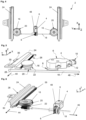
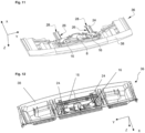
- Figures 1 and 2 show an actuating device 2 of a mobile aerodynamic blade (reference 36 on figure 6 ) for an automotive vehicle 40 rear spoiler 42.
- this actuating device 2 cooperates with the mobile aerodynamic blade 36 and is placed in a cavity of an automotive vehicle 40 rear spoiler 42, more specifically between an inner panel and an outer panel constituting the rear spoiler 42.
- This rear spoiler 42 has an opening in its rear side following a longitudinal axis (direction X) of the automotive vehicle 40 on which the rear spoiler 42 is mounted, this opening allows the mobile aerodynamic blade to go back and forth depending on the speed of the automotive vehicle 40.
- the mobile aerodynamic blade 36 and the rear spoiler 42 shown on figure 7 , are known for a skilled person and will not be described in details in this application.
- the actuating device comprises a drive unit 4 comprising a motor 6 and a main gear wheel 8.
- the motor 6 comprises an outlet axis on which the main gear wheel 8 is mounted in order to be set in motion by the motor 6.
- the motor 6 is able to set the main gear wheel 8 in motion in two opposite directions.
- the outlet axis of the motor 6 is linked to an endless screw 48 in contact with the main gear wheel 8 (in this case the main gear wheel 8 can be rotatable around an horizontal axis).
- the motor 6 is able to set the endless screw in motion, and consequently the main gear wheel 8, in two opposite directions.
- the actuating device 2 comprises a connector 10 to be linked to a power supply.
- the motor 6 is connected to an electronic control unit configured to activate this latter in order to deploy and retract the mobile aerodynamic blade in function of the automotive vehicle 40 speed as explained above.
- the motor 6 also comprises attaching means 12, for example screws, to attach this latter to a main body 14 of the actuating device shown on figures 4 and 5 .
- the actuating device 2 also comprises at least one outer gear wheel 16, advantageously two as illustrated on the figures.
- the outer gear wheel is a double gear wheel. In the following description, we are going to described this possibility using the terms “double gear wheel 16' " .
- the double gears wheels 16 are connected to the main gear wheel 8 by a transmission of movement element 18. More precisely, the transmission of movement element 18 is connected to the main gear wheel and to a first level 20 of the double gear wheels 16. In this configuration, the double gear wheels 16 are set in motion by the motor 6 and can be placed far from this latter. As described below, each other second level 22 of the double gear wheels 16 is in contact with a sliding unit 24 allowing to deploy and retract the mobile aerodynamic blade 36. The second level 22 cooperating with the sliding unit has a larger diameter than first level 20 cooperating with the transmission of movement element 18.
- the two double gear wheels 16 are arranged on both sides of the main gear wheel.
- the main gear wheel 8 is centered relative to the double gear wheels 16.
- the two assemblies double gear wheel 16 / sliding unit 24 are placed at the two extremities of the spoiler following a transverse direction (direction Y) of the automotive vehicle 40 on which the rear spoiler 42 is mounted. This allows a better guiding of the mobile aerodynamic blade.
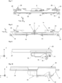
- All gear wheels of the actuating device 2 illustrated on the figures can be rotatable around different vertical axes of rotation when the actuating device is mounted in the automotive vehicle 40 rear spoiler 42, as illustrated on figures 1, 2 , 5 , 7 and 9 .
- the main gear wheel 8 and the double gear wheels 16 extend in a horizontal direction, which allows reducing the size of the actuating device 2 in a vertical direction (direction Z) of an automotive vehicle 40 comprising a rear spoiler 42 in which the actuating device 2 is placed.
- the motor 6 is turned according a 90° angle regarding to the actuator of the prior art in order to place the main gear wheel 8 in such a horizontal direction.
- the main gear wheel 8 can be rotatable around a horizontal axis and the double gear wheels 16 can be rotatable around two different vertical axes. This configuration allows to use a different transmission of movement element 18 as described below.
- the main gear wheel 8 and the double gear wheels 16 can be aligned, preferably in a longitudinal direction of the rear spoiler 42 in order to obtain a smaller actuating device 2 in a vertical direction.
- the transmission of movement element 18 can be formed by a rack (for greater sustainability and yield), by an endless screw (flexible and consequently easy to integrate), by a helix flexible shaft placed into a sheath open in the contact areas between the endless screw and the main and double gear wheels. More broadly, the transmission of movement element 18 is able to perform a linear transmission of tensile and compressive force. This latter may be a push pull cable or a helix cable.
- the rack is translated in an opposite direction than for the deployment of the mobile aerodynamic blade 36 and sets in rotation, thanks to this movement, the double gear wheels 16 in an opposite direction than for the deployment of the mobile aerodynamic blade 36. These latter allow, thanks to the sliding units 24, to retract the mobile aerodynamic blade 36.
- the transmission of movement element 18 is formed by an endless screw, this latter is in contact with teeth of the main gear wheel 8 and of the first level 20 of the double gear wheels 16.
- the endless screw is also set in rotation and translated (translational direction 46) in one direction and sets in rotation, thanks to this movement, the double gear wheels 16.
- the double gear wheels 16, which cooperate with sliding units 24, allow deploying the mobile aerodynamic blade 36 (thanks to the translational direction 44 of the sliding units 24).
- the motor 6 sets in rotation the main gear wheel 8 in an opposite direction than for the deployment of the mobile aerodynamic blade 36.
- the endless screw is set in rotation and translated in an opposite direction than for the deployment of the mobile aerodynamic blade 36 and sets in rotation, thanks to this movement, the double gear wheels 16 in an opposite direction than for the deployment of the mobile aerodynamic blade 36. These latter allow, thanks to the sliding units 24, to retract the mobile aerodynamic blade 36.
- the transmission of movement element 18 is formed by a helix flexible shaft placed into a sheath open in the contact areas between the helix flexible shaft and the main and double gear wheels, this latter is in contact with teeth of the main gear wheel 8 and of the first level 20 of the double gear wheels 16.
- the main gear wheel 8 is set in rotation by the motor 6, the helix flexible shaft is translated (translational direction 46) in one direction and sets in rotation, thanks to this movement, the double gear wheels 16.
- the double gear wheels 16, which cooperate with sliding units 24, allow deploying the mobile aerodynamic blade 36 (thanks to the translational direction 44 of the sliding units 24).
- the motor 6 sets in rotation the main gear wheel 8 in an opposite direction than for the deployment of the mobile aerodynamic blade 36.
- the helix flexible shaft is translated in an opposite direction than for the deployment of the mobile aerodynamic blade 36 and sets in rotation, thanks to this movement, the double gear wheels 16 in an opposite direction than for the deployment of the mobile aerodynamic blade 36. These latter allow, thanks to the sliding units 24, to retract the mobile aerodynamic blade 36.
- Figures 3 , 4 and 6 illustrate another embodiment in which the transmission of movement element 18 is a rod integral with the main gear wheel (8) and comprising areas formed by a screw thread in contact with the outer gear wheel 16, with the first level 20 of the double gear wheel 16 on figures.
- the endless screw 48 linked to the outlet axis of the motor 6 sets in rotation the main gear wheel 8.
- the rod is also set in rotation. Consequently, the areas formed by a screw thread set in rotation the double gear wheels 16 which, cooperating with sliding units 24, allow deploying the mobile aerodynamic blade 36 (thanks to the translational direction 44 of the sliding units 24).
- the endless screw 48 sets in rotation the main gear wheel 8 in an opposite direction than for the deployment of the mobile aerodynamic blade 36.
- the rod is also put in rotation in an opposite direction than for the deployment of the mobile aerodynamic blade 36 and sets in rotation, thanks to this movement, the double gear wheels 16 in an opposite direction than for the deployment of the mobile aerodynamic blade 36. These latter allow, thanks to the sliding units 24, to retract the mobile aerodynamic blade 36.
- the sliding units 24 can be formed by a rack 26 cooperating with the second level 22 of the double gear wheels 16 and a slide 28 arranged for guiding the mobile aerodynamic blade 36. Only one sliding unit 24 is illustrated on figures 5 and 6 cooperating with one double gear wheel 16. The configuration is the same for the other double gear wheel 16 ( figures 3 and 4 , two double gear wheels 16 with two sliding units 24).
- the rack is oriented in order to cooperate with the second level 22 of a double gear wheel 16.
- the rack 26 and the slide 28 can be parts of a unique piece which ensure both guiding and motion transfer functions.
- the mobile aerodynamic blade main body 38 is rigidly attached to the slides 28, for example using the through holes 30 shown on figures 7 to 10 and cooperating with other through holes made into the mobile aerodynamic blade main body 38 and attaching means such as screws or rivets.
- Other ways to attach the mobile aerodynamic blade main body 38 to the sliding units 24 are possible and known by a skilled person. Obviously, these latter are not directly attached to the main body 14 of the actuating device 2 in order to move when the motor 6 is activated.
- the configuration with two sliding units 24 as shown on figures is interesting because it allows to shorten the slide 28 and the rack 24 regarding the actuating devices of the prior art because the gear ratio between the main gear wheel 8 and the double gear wheels 16 is different. Thus, the actuating device 2 has no impact on the rear spoiler 42 sealing.
- the rack 26 could be formed directly on the mobile aerodynamic blade main body 38, for example during the molding process of this latter.
- the slide 28 is a piece separated from the rack.
- the rack 26 and the slide 28 are two pieces different from the mobile aerodynamic blade main body 38.
- the double gear wheels 16 are set in rotation when a deployment or a retraction of the mobile aerodynamic blade 36 is needed.
- the second level 22 of the gear wheels 16 allows to translate the sliding units 24 thanks to the rack 26 in two opposite directions in order to deploy or retract the mobile aerodynamic blade 36.
- these latter can guide the mobile aerodynamic blade 36 in a vertical direction (direction Z) and in a transverse direction (Y) of the automotive vehicle 40 on which the mobile aerodynamic blade 36 is mounted.
- the actuating device also comprises a main body 14 (visible on figures 4 and 5 ) on which the motor 6 and the rotation axes of the double gear wheels can be attached.
- the other parts of the actuating device 2 transmission of movement element 18, sliding units 24, etc. are not attached to the main body 14.
- the main body 14 of the actuating device 2 is attached (glued, screwed, etc.) to an attachment element 32 which allow to connect the main body 14 of the actuating device to a wall of the rear spoiler 42 cavity (after having attach the mobile aerodynamic blade 36 on the actuating device).
- This attachment element has a form designed to cooperate with the actuating device 2 and the rear spoiler 42 wall, with a first part attached to the actuating device 2 and a second part forming a right angle with the first part in the example of figures 4 and 5 .
- Screws 34 can be used to attach the attachment element to the rear spoiler 42 wall. It is interesting to use reversible attaching means to be able to remove the assembly formed by the actuating device 2 and the mobile from the rear spoiler 42 cavity in sliding this assembly after attaching means removal and without any need to remove a part of the rear spoiler 42, for example the inner panel. This is interesting to simplify the maintenance of the system, for example in case of mechanical issues with the mobile aerodynamic blade.
Landscapes
- Engineering & Computer Science (AREA)
- Chemical & Material Sciences (AREA)
- Combustion & Propulsion (AREA)
- Transportation (AREA)
- Mechanical Engineering (AREA)
- Physics & Mathematics (AREA)
- Fluid Mechanics (AREA)
- Power-Operated Mechanisms For Wings (AREA)
- Gear Transmission (AREA)
Claims (14)
- Betätigungsvorrichtung (2) für ein bewegliches aerodynamisches Blatt für einen Heckspoiler (42) eines Kraftfahrzeugs (40), aufweisend eine Antriebseinheit (4), die einen Motor (6) und ein Hauptzahnrad (8) aufweist, wobei die Betätigungsvorrichtung (2) aufweist:- mindestens ein Außenzahnrad (16), und- ein Bewegungsübertragungselement (18),wobei das Bewegungsübertragungselement (18) mit dem Hauptzahnrad (8) und dem Außenzahnrad (16) verbunden ist, wobei das Außenzahnrad (16) mit einer Gleiteinheit (24) zusammenwirkt, die das Ausfahren und Einfahren des beweglichen aerodynamischen Blatts ermöglicht, dadurch gekennzeichnet, dass das Außenzahnrad (16) ein Doppelzahnrad ist, das eine erste Ebene (20), die mit dem Bewegungsübertragungselement (18) zusammenwirkt, und eine zweite Ebene (22), die mit der Gleiteinheit (24) zusammenwirkt, aufweist.
- Betätigungsvorrichtung (2) nach Anspruch 1, aufweisend zwei Außenzahnräder (16), die mit zwei Gleiteinheiten (24) zusammenwirken, mit dem Bewegungsübertragungselement (18) verbunden sind und auf beiden Seiten des Hauptzahnrads (8) angeordnet sind.
- Betätigungsvorrichtung (2) nach einem der vorhergehenden Ansprüche, wobei das Hauptzahnrad (8) und das Außenzahnrad (16) um unterschiedliche vertikale Drehachsen drehbar sind, wenn die Betätigungsvorrichtung (2) in dem Heckspoiler (42) des Kraftfahrzeugs (40) montiert ist.
- Betätigungsvorrichtung (2) nach Anspruch 1 oder 2, wobei das Außenzahnrad (16) um eine vertikale Drehachse und das Hauptzahnrad (8) um eine horizontale Drehachse drehbar ist, wenn die Betätigungsvorrichtung (2) in dem Heckspoiler (42) des Kraftfahrzeugs (40) montiert ist.
- Betätigungsvorrichtung (2) nach einem der vorhergehenden Ansprüche, wobei das Hauptzahnrad (8) und das Außenzahnrad (16), vorzugsweise in einer Längsrichtung (X) des Heckspoilers (42), fluchten.
- Betätigungsvorrichtung (2) nach einem der vorhergehenden Ansprüche, wobei das Bewegungsübertragungselement (18) gebildet ist durch:- eine Zahnstange,- eine Endlosschraube,- eine schraubenförmige biegsame Welle, die in einer in den Kontaktbereichen zwischen der Endlosschraube und dem Hauptzahnrad (8) und dem Doppelzahnrad (16) offenen Hülse angeordnet ist, oder- einer mit dem Hauptzahnrad (8) fest verbundenen Stange, die Bereiche aufweist, die durch ein Schraubengewinde gebildet werden, das in Kontakt mit dem äußeren Zahnrad (16) steht.
- Betätigungsvorrichtung (2) nach einem der vorhergehenden Ansprüche,
dadurch gekennzeichnet, dass die Gleiteinheit (24) eine mit dem Außenzahnrad (16) zusammenwirkende Zahnstange (26) und einen Schlitten (28) aufweist, der zur Führung des beweglichen aerodynamischen Blatts (36) dient. - Betätigungsvorrichtung (2) nach einem der vorhergehenden Ansprüche, wobei der Motor (6) mit einer elektronischen Steuereinheit verbunden ist, die so beschaffen ist, dass sie das Ausfahren und das Einfahren des beweglichen aerodynamischen Blatts (36) in Abhängigkeit von der Geschwindigkeit des Kraftfahrzeugs (40) steuert.
- Betätigungsvorrichtung (2) nach einem der vorhergehenden Ansprüche, wobei die Antriebseinheit (4) und eine Drehachse des Außenzahnrades (16) an einem Hauptkörper (14) der Betätigungsvorrichtung (2) befestigt sind, wobei der Hauptkörper (14) an einem Befestigungselement (32) befestigt ist, das zur Befestigung der Betätigungsvorrichtung (2) an einem Heckspoiler (42) eines Kraftfahrzeugs (40) angeordnet ist.
- Bewegliches aerodynamisches Blatt (36) für einen Heckspoiler (42) eines Kraftfahrzeugs (40) mit einer Betätigungsvorrichtung (2) nach einem der vorhergehenden Ansprüche.
- Bewegliches aerodynamisches Blatt (36) nach Anspruch 10, wobei die mit dem äußeren Zahnrad (16) zusammenwirkende Zahnstange (26) einstückig mit einem Hauptkörper (38) des beweglichen aerodynamischen Blatts (36) ausgebildet ist.
- Bewegliches aerodynamisches Blatt (36) nach Anspruch 10, dadurch gekennzeichnet, dass die mit dem äußeren Zahnrad (16) zusammenwirkende Zahnstange (26) und der zur Führung des beweglichen aerodynamischen Blatts (36) angeordnete Schlitten (28) ein einziges Teil bilden, an dem ein Hauptkörper (38) des beweglichen aerodynamischen Blatts (36) befestigt ist.
- Kraftfahrzeug-Heckspoiler (42) aufweisend ein bewegliches aerodynamisches Blatt (36) nach einem der Ansprüche 10 bis 12, das in einem in einem Hauptkörper des Heckspoilers (42) ausgebildeten Hohlraum angeordnet ist.
- Kraftfahrzeug-Heckspoiler (42) nach Anspruch 13, wobei das bewegliche aerodynamische Blatt (36) mit einem sich in Längsrichtung des Kraftfahrzeugs (40) erstreckenden Befestigungselement (32) an dem Hauptkörper des Heckspoilers (42) befestigt ist und an einem Hauptkörper (14) der Betätigungsvorrichtung (2) angebracht ist, an dem der Antrieb (4) und eine Drehachse des Doppelzahnrads (16) befestigt sind.
Priority Applications (1)
| Application Number | Priority Date | Filing Date | Title |
|---|---|---|---|
| EP20306502.4A EP4008613B1 (de) | 2020-12-04 | 2020-12-04 | Betätigungsvorrichtung für ein bewegliches aerodynamisches blatt eines kraftfahrzeugheckspoilers |
Applications Claiming Priority (1)
| Application Number | Priority Date | Filing Date | Title |
|---|---|---|---|
| EP20306502.4A EP4008613B1 (de) | 2020-12-04 | 2020-12-04 | Betätigungsvorrichtung für ein bewegliches aerodynamisches blatt eines kraftfahrzeugheckspoilers |
Publications (2)
| Publication Number | Publication Date |
|---|---|
| EP4008613A1 EP4008613A1 (de) | 2022-06-08 |
| EP4008613B1 true EP4008613B1 (de) | 2025-05-28 |
Family
ID=74129977
Family Applications (1)
| Application Number | Title | Priority Date | Filing Date |
|---|---|---|---|
| EP20306502.4A Active EP4008613B1 (de) | 2020-12-04 | 2020-12-04 | Betätigungsvorrichtung für ein bewegliches aerodynamisches blatt eines kraftfahrzeugheckspoilers |
Country Status (1)
| Country | Link |
|---|---|
| EP (1) | EP4008613B1 (de) |
Families Citing this family (1)
| Publication number | Priority date | Publication date | Assignee | Title |
|---|---|---|---|---|
| CN115042883A (zh) * | 2022-06-13 | 2022-09-13 | 吉林大学 | 一种卡车尾部可调节导流板 |
Family Cites Families (4)
| Publication number | Priority date | Publication date | Assignee | Title |
|---|---|---|---|---|
| US20040174043A1 (en) * | 2003-03-06 | 2004-09-09 | Ross Bradsen | Motorized rack and pinion assembly |
| DE10348284A1 (de) * | 2003-10-17 | 2005-05-12 | Porsche Ag | Stellantrieb für einen Spoiler eines Kraftfahrzeugs, insbesondere für einen Heckspoiler |
| FR2991281B1 (fr) * | 2012-05-30 | 2014-06-20 | Rehau Sa | Becquet arriere mobile pour vehicule automobile. |
| DE102018119906B4 (de) * | 2018-08-16 | 2025-11-13 | Dr. Ing. H.C. F. Porsche Aktiengesellschaft | Antriebsanordnung für Kfz-Funktionsteil |
-
2020
- 2020-12-04 EP EP20306502.4A patent/EP4008613B1/de active Active
Also Published As
| Publication number | Publication date |
|---|---|
| EP4008613A1 (de) | 2022-06-08 |
Similar Documents
| Publication | Publication Date | Title |
|---|---|---|
| EP2470413B1 (de) | Variable aerodynamische vorrichtung | |
| CA2618118C (en) | Adjustable cab extender | |
| EP2154015B1 (de) | Modulanordnungen für ein Fahrzeug-Panoramadach | |
| CN104176136B (zh) | 用于车辆的空气导向装置 | |
| CN112805171B (zh) | 显示设备和具有显示设备的机动车 | |
| US6193302B1 (en) | Motor vehicle including a deployable spoiler | |
| US20240359546A1 (en) | Flow guiding device for being installed on a panel component | |
| CN101585378B (zh) | 汽车 | |
| US6746073B2 (en) | Lock system for a cabriolet convertible top | |
| CN1960889A (zh) | 用于汽车透明车顶的内遮阳罩 | |
| EP3498577B1 (de) | Beweglicher unterbauter flügel | |
| EP2660089A1 (de) | Schattenvorrichtung | |
| DE3541902A1 (de) | Blendschutzeinrichtung fuer kraftfahrzeuge | |
| CN104276064A (zh) | 可调节头枕组件 | |
| EP4008613A1 (de) | Betätigungsvorrichtung für ein bewegliches aerodynamisches blatt eines kraftfahrzeugheckspoilers | |
| CN116142085A (zh) | 用于安装到机动车面板构件的传感器模块和相关面板构件 | |
| EP3369594B1 (de) | Benutzerbetätigter luftdüsenregelungsmechanismus und verfahren zur regelung des luftstroms | |
| CN118529119A (zh) | 具有减小的封装空间的平移转向柱 | |
| CN218172381U (zh) | 一种线控转向长行程调节转向柱 | |
| US20250276731A1 (en) | Steering system for motor vehicle and motor vehicle comprising the same | |
| CN111356627B (zh) | 带有移动板的车辆活动后扩散器 | |
| CN119907762A (zh) | 具有伸缩臂以及用于操纵该臂的机电致动器的转向柱组件 | |
| US11904930B2 (en) | Steering column for a motor vehicle | |
| CN101016026A (zh) | 车顶自动开关设备 | |
| US20250121894A1 (en) | Dual spoiler apparatus |
Legal Events
| Date | Code | Title | Description |
|---|---|---|---|
| PUAI | Public reference made under article 153(3) epc to a published international application that has entered the european phase |
Free format text: ORIGINAL CODE: 0009012 |
|
| STAA | Information on the status of an ep patent application or granted ep patent |
Free format text: STATUS: THE APPLICATION HAS BEEN PUBLISHED |
|
| AK | Designated contracting states |
Kind code of ref document: A1 Designated state(s): AL AT BE BG CH CY CZ DE DK EE ES FI FR GB GR HR HU IE IS IT LI LT LU LV MC MK MT NL NO PL PT RO RS SE SI SK SM TR |
|
| STAA | Information on the status of an ep patent application or granted ep patent |
Free format text: STATUS: REQUEST FOR EXAMINATION WAS MADE |
|
| 17P | Request for examination filed |
Effective date: 20221027 |
|
| RBV | Designated contracting states (corrected) |
Designated state(s): AL AT BE BG CH CY CZ DE DK EE ES FI FR GB GR HR HU IE IS IT LI LT LU LV MC MK MT NL NO PL PT RO RS SE SI SK SM TR |
|
| RAP3 | Party data changed (applicant data changed or rights of an application transferred) |
Owner name: SUSPA GMBH Owner name: OPMOBILITY SE |
|
| RAP3 | Party data changed (applicant data changed or rights of an application transferred) |
Owner name: SUSPA GMBH Owner name: OPMOBILITY SE |
|
| GRAP | Despatch of communication of intention to grant a patent |
Free format text: ORIGINAL CODE: EPIDOSNIGR1 |
|
| STAA | Information on the status of an ep patent application or granted ep patent |
Free format text: STATUS: GRANT OF PATENT IS INTENDED |
|
| INTG | Intention to grant announced |
Effective date: 20241219 |
|
| GRAS | Grant fee paid |
Free format text: ORIGINAL CODE: EPIDOSNIGR3 |
|
| GRAA | (expected) grant |
Free format text: ORIGINAL CODE: 0009210 |
|
| STAA | Information on the status of an ep patent application or granted ep patent |
Free format text: STATUS: THE PATENT HAS BEEN GRANTED |
|
| AK | Designated contracting states |
Kind code of ref document: B1 Designated state(s): AL AT BE BG CH CY CZ DE DK EE ES FI FR GB GR HR HU IE IS IT LI LT LU LV MC MK MT NL NO PL PT RO RS SE SI SK SM TR |
|
| REG | Reference to a national code |
Ref country code: GB Ref legal event code: FG4D |
|
| REG | Reference to a national code |
Ref country code: CH Ref legal event code: EP |
|
| REG | Reference to a national code |
Ref country code: DE Ref legal event code: R096 Ref document number: 602020051969 Country of ref document: DE |
|
| REG | Reference to a national code |
Ref country code: IE Ref legal event code: FG4D |
|
| REG | Reference to a national code |
Ref country code: NL Ref legal event code: MP Effective date: 20250528 |
|
| PG25 | Lapsed in a contracting state [announced via postgrant information from national office to epo] |
Ref country code: FI Free format text: LAPSE BECAUSE OF FAILURE TO SUBMIT A TRANSLATION OF THE DESCRIPTION OR TO PAY THE FEE WITHIN THE PRESCRIBED TIME-LIMIT Effective date: 20250528 Ref country code: ES Free format text: LAPSE BECAUSE OF FAILURE TO SUBMIT A TRANSLATION OF THE DESCRIPTION OR TO PAY THE FEE WITHIN THE PRESCRIBED TIME-LIMIT Effective date: 20250528 |
|
| REG | Reference to a national code |
Ref country code: LT Ref legal event code: MG9D |
|
| PG25 | Lapsed in a contracting state [announced via postgrant information from national office to epo] |
Ref country code: GR Free format text: LAPSE BECAUSE OF FAILURE TO SUBMIT A TRANSLATION OF THE DESCRIPTION OR TO PAY THE FEE WITHIN THE PRESCRIBED TIME-LIMIT Effective date: 20250829 Ref country code: NO Free format text: LAPSE BECAUSE OF FAILURE TO SUBMIT A TRANSLATION OF THE DESCRIPTION OR TO PAY THE FEE WITHIN THE PRESCRIBED TIME-LIMIT Effective date: 20250828 |
|
| PG25 | Lapsed in a contracting state [announced via postgrant information from national office to epo] |
Ref country code: NL Free format text: LAPSE BECAUSE OF FAILURE TO SUBMIT A TRANSLATION OF THE DESCRIPTION OR TO PAY THE FEE WITHIN THE PRESCRIBED TIME-LIMIT Effective date: 20250528 Ref country code: PL Free format text: LAPSE BECAUSE OF FAILURE TO SUBMIT A TRANSLATION OF THE DESCRIPTION OR TO PAY THE FEE WITHIN THE PRESCRIBED TIME-LIMIT Effective date: 20250528 |
|
| PG25 | Lapsed in a contracting state [announced via postgrant information from national office to epo] |
Ref country code: BG Free format text: LAPSE BECAUSE OF FAILURE TO SUBMIT A TRANSLATION OF THE DESCRIPTION OR TO PAY THE FEE WITHIN THE PRESCRIBED TIME-LIMIT Effective date: 20250528 |
|
| PG25 | Lapsed in a contracting state [announced via postgrant information from national office to epo] |
Ref country code: HR Free format text: LAPSE BECAUSE OF FAILURE TO SUBMIT A TRANSLATION OF THE DESCRIPTION OR TO PAY THE FEE WITHIN THE PRESCRIBED TIME-LIMIT Effective date: 20250528 |
|
| PG25 | Lapsed in a contracting state [announced via postgrant information from national office to epo] |
Ref country code: RS Free format text: LAPSE BECAUSE OF FAILURE TO SUBMIT A TRANSLATION OF THE DESCRIPTION OR TO PAY THE FEE WITHIN THE PRESCRIBED TIME-LIMIT Effective date: 20250828 |
|
| PG25 | Lapsed in a contracting state [announced via postgrant information from national office to epo] |
Ref country code: IS Free format text: LAPSE BECAUSE OF FAILURE TO SUBMIT A TRANSLATION OF THE DESCRIPTION OR TO PAY THE FEE WITHIN THE PRESCRIBED TIME-LIMIT Effective date: 20250928 |
|
| PG25 | Lapsed in a contracting state [announced via postgrant information from national office to epo] |
Ref country code: LV Free format text: LAPSE BECAUSE OF FAILURE TO SUBMIT A TRANSLATION OF THE DESCRIPTION OR TO PAY THE FEE WITHIN THE PRESCRIBED TIME-LIMIT Effective date: 20250528 |
|
| REG | Reference to a national code |
Ref country code: AT Ref legal event code: MK05 Ref document number: 1798503 Country of ref document: AT Kind code of ref document: T Effective date: 20250528 |
|
| PG25 | Lapsed in a contracting state [announced via postgrant information from national office to epo] |
Ref country code: AT Free format text: LAPSE BECAUSE OF FAILURE TO SUBMIT A TRANSLATION OF THE DESCRIPTION OR TO PAY THE FEE WITHIN THE PRESCRIBED TIME-LIMIT Effective date: 20250528 Ref country code: SM Free format text: LAPSE BECAUSE OF FAILURE TO SUBMIT A TRANSLATION OF THE DESCRIPTION OR TO PAY THE FEE WITHIN THE PRESCRIBED TIME-LIMIT Effective date: 20250528 Ref country code: DK Free format text: LAPSE BECAUSE OF FAILURE TO SUBMIT A TRANSLATION OF THE DESCRIPTION OR TO PAY THE FEE WITHIN THE PRESCRIBED TIME-LIMIT Effective date: 20250528 |
|
| PG25 | Lapsed in a contracting state [announced via postgrant information from national office to epo] |
Ref country code: CZ Free format text: LAPSE BECAUSE OF FAILURE TO SUBMIT A TRANSLATION OF THE DESCRIPTION OR TO PAY THE FEE WITHIN THE PRESCRIBED TIME-LIMIT Effective date: 20250528 |
|
| PG25 | Lapsed in a contracting state [announced via postgrant information from national office to epo] |
Ref country code: EE Free format text: LAPSE BECAUSE OF FAILURE TO SUBMIT A TRANSLATION OF THE DESCRIPTION OR TO PAY THE FEE WITHIN THE PRESCRIBED TIME-LIMIT Effective date: 20250528 |
|
| PG25 | Lapsed in a contracting state [announced via postgrant information from national office to epo] |
Ref country code: SK Free format text: LAPSE BECAUSE OF FAILURE TO SUBMIT A TRANSLATION OF THE DESCRIPTION OR TO PAY THE FEE WITHIN THE PRESCRIBED TIME-LIMIT Effective date: 20250528 |
|
| PG25 | Lapsed in a contracting state [announced via postgrant information from national office to epo] |
Ref country code: IT Free format text: LAPSE BECAUSE OF FAILURE TO SUBMIT A TRANSLATION OF THE DESCRIPTION OR TO PAY THE FEE WITHIN THE PRESCRIBED TIME-LIMIT Effective date: 20250528 |
|
| REG | Reference to a national code |
Ref country code: DE Ref legal event code: R097 Ref document number: 602020051969 Country of ref document: DE |
|
| PG25 | Lapsed in a contracting state [announced via postgrant information from national office to epo] |
Ref country code: RO Free format text: LAPSE BECAUSE OF FAILURE TO SUBMIT A TRANSLATION OF THE DESCRIPTION OR TO PAY THE FEE WITHIN THE PRESCRIBED TIME-LIMIT Effective date: 20250528 |
|
| PLBE | No opposition filed within time limit |
Free format text: ORIGINAL CODE: 0009261 |
|
| STAA | Information on the status of an ep patent application or granted ep patent |
Free format text: STATUS: NO OPPOSITION FILED WITHIN TIME LIMIT |
|
| REG | Reference to a national code |
Ref country code: CH Ref legal event code: L10 Free format text: ST27 STATUS EVENT CODE: U-0-0-L10-L00 (AS PROVIDED BY THE NATIONAL OFFICE) Effective date: 20260409 |
|
| 26N | No opposition filed |
Effective date: 20260303 |