EP4008532B1 - System und verfahren zur platzierung von verbundlagen - Google Patents
System und verfahren zur platzierung von verbundlagen Download PDFInfo
- Publication number
- EP4008532B1 EP4008532B1 EP21208618.5A EP21208618A EP4008532B1 EP 4008532 B1 EP4008532 B1 EP 4008532B1 EP 21208618 A EP21208618 A EP 21208618A EP 4008532 B1 EP4008532 B1 EP 4008532B1
- Authority
- EP
- European Patent Office
- Prior art keywords
- ply
- carrier
- transfer
- chuck
- end effector
- Prior art date
- Legal status (The legal status is an assumption and is not a legal conclusion. Google has not performed a legal analysis and makes no representation as to the accuracy of the status listed.)
- Active
Links
Images


Classifications
-
- B—PERFORMING OPERATIONS; TRANSPORTING
- B29—WORKING OF PLASTICS; WORKING OF SUBSTANCES IN A PLASTIC STATE IN GENERAL
- B29C—SHAPING OR JOINING OF PLASTICS; SHAPING OF MATERIAL IN A PLASTIC STATE, NOT OTHERWISE PROVIDED FOR; AFTER-TREATMENT OF THE SHAPED PRODUCTS, e.g. REPAIRING
- B29C70/00—Shaping composites, i.e. plastics material comprising reinforcements, fillers or preformed parts, e.g. inserts
- B29C70/04—Shaping composites, i.e. plastics material comprising reinforcements, fillers or preformed parts, e.g. inserts comprising reinforcements only, e.g. self-reinforcing plastics
- B29C70/28—Shaping operations therefor
- B29C70/30—Shaping by lay-up, i.e. applying fibres, tape or broadsheet on a mould, former or core; Shaping by spray-up, i.e. spraying of fibres on a mould, former or core
- B29C70/38—Automated lay-up, e.g. using robots, laying filaments according to predetermined patterns
-
- B—PERFORMING OPERATIONS; TRANSPORTING
- B65—CONVEYING; PACKING; STORING; HANDLING THIN OR FILAMENTARY MATERIAL
- B65G—TRANSPORT OR STORAGE DEVICES, e.g. CONVEYORS FOR LOADING OR TIPPING, SHOP CONVEYOR SYSTEMS OR PNEUMATIC TUBE CONVEYORS
- B65G47/00—Article or material-handling devices associated with conveyors; Methods employing such devices
- B65G47/74—Feeding, transfer, or discharging devices of particular kinds or types
- B65G47/90—Devices for picking-up and depositing articles or materials
- B65G47/92—Devices for picking-up and depositing articles or materials incorporating electrostatic or magnetic grippers
-
- B—PERFORMING OPERATIONS; TRANSPORTING
- B25—HAND TOOLS; PORTABLE POWER-DRIVEN TOOLS; MANIPULATORS
- B25J—MANIPULATORS; CHAMBERS PROVIDED WITH MANIPULATION DEVICES
- B25J15/00—Gripping heads and other end effectors
- B25J15/06—Gripping heads and other end effectors with vacuum or magnetic holding means
- B25J15/0608—Gripping heads and other end effectors with vacuum or magnetic holding means with magnetic holding means
-
- B—PERFORMING OPERATIONS; TRANSPORTING
- B25—HAND TOOLS; PORTABLE POWER-DRIVEN TOOLS; MANIPULATORS
- B25J—MANIPULATORS; CHAMBERS PROVIDED WITH MANIPULATION DEVICES
- B25J15/00—Gripping heads and other end effectors
- B25J15/06—Gripping heads and other end effectors with vacuum or magnetic holding means
- B25J15/0616—Gripping heads and other end effectors with vacuum or magnetic holding means with vacuum
-
- B—PERFORMING OPERATIONS; TRANSPORTING
- B25—HAND TOOLS; PORTABLE POWER-DRIVEN TOOLS; MANIPULATORS
- B25J—MANIPULATORS; CHAMBERS PROVIDED WITH MANIPULATION DEVICES
- B25J9/00—Program-controlled manipulators
- B25J9/02—Program-controlled manipulators characterised by movement of the arms, e.g. cartesian coordinate type
- B25J9/023—Cartesian coordinate type
- B25J9/026—Gantry-type
-
- B—PERFORMING OPERATIONS; TRANSPORTING
- B29—WORKING OF PLASTICS; WORKING OF SUBSTANCES IN A PLASTIC STATE IN GENERAL
- B29C—SHAPING OR JOINING OF PLASTICS; SHAPING OF MATERIAL IN A PLASTIC STATE, NOT OTHERWISE PROVIDED FOR; AFTER-TREATMENT OF THE SHAPED PRODUCTS, e.g. REPAIRING
- B29C31/00—Handling, e.g. feeding of the material to be shaped, storage of plastics material before moulding; Automation, i.e. automated handling lines in plastics processing plants, e.g. using manipulators or robots
- B29C31/04—Feeding of the material to be moulded, e.g. into a mould cavity
- B29C31/08—Feeding of the material to be moulded, e.g. into a mould cavity of preforms to be moulded, e.g. tablets, fibre reinforced preforms, extruded ribbons, tubes or profiles; Manipulating means specially adapted for feeding preforms, e.g. supports conveyors
-
- B—PERFORMING OPERATIONS; TRANSPORTING
- B29—WORKING OF PLASTICS; WORKING OF SUBSTANCES IN A PLASTIC STATE IN GENERAL
- B29C—SHAPING OR JOINING OF PLASTICS; SHAPING OF MATERIAL IN A PLASTIC STATE, NOT OTHERWISE PROVIDED FOR; AFTER-TREATMENT OF THE SHAPED PRODUCTS, e.g. REPAIRING
- B29C70/00—Shaping composites, i.e. plastics material comprising reinforcements, fillers or preformed parts, e.g. inserts
- B29C70/04—Shaping composites, i.e. plastics material comprising reinforcements, fillers or preformed parts, e.g. inserts comprising reinforcements only, e.g. self-reinforcing plastics
- B29C70/28—Shaping operations therefor
- B29C70/54—Component parts, details or accessories; Auxiliary operations, e.g. feeding or storage of prepregs or SMC after impregnation or during ageing
- B29C70/541—Positioning reinforcements in a mould, e.g. using clamping means for the reinforcement
-
- B—PERFORMING OPERATIONS; TRANSPORTING
- B32—LAYERED PRODUCTS
- B32B—LAYERED PRODUCTS, i.e. PRODUCTS BUILT-UP OF STRATA OF FLAT OR NON-FLAT, e.g. CELLULAR OR HONEYCOMB, FORM
- B32B37/00—Methods or apparatus for laminating, e.g. by curing or by ultrasonic bonding
-
- B—PERFORMING OPERATIONS; TRANSPORTING
- B65—CONVEYING; PACKING; STORING; HANDLING THIN OR FILAMENTARY MATERIAL
- B65H—HANDLING THIN OR FILAMENTARY MATERIAL, e.g. SHEETS, WEBS, CABLES
- B65H5/00—Feeding articles separated from piles; Feeding articles to machines
- B65H5/08—Feeding articles separated from piles; Feeding articles to machines by grippers, e.g. suction grippers
- B65H5/10—Reciprocating or oscillating grippers, e.g. suction or gripper tables
-
- B—PERFORMING OPERATIONS; TRANSPORTING
- B65—CONVEYING; PACKING; STORING; HANDLING THIN OR FILAMENTARY MATERIAL
- B65H—HANDLING THIN OR FILAMENTARY MATERIAL, e.g. SHEETS, WEBS, CABLES
- B65H5/00—Feeding articles separated from piles; Feeding articles to machines
- B65H5/08—Feeding articles separated from piles; Feeding articles to machines by grippers, e.g. suction grippers
- B65H5/14—Details of grippers; Actuating-mechanisms therefor
-
- B—PERFORMING OPERATIONS; TRANSPORTING
- B29—WORKING OF PLASTICS; WORKING OF SUBSTANCES IN A PLASTIC STATE IN GENERAL
- B29L—INDEXING SCHEME ASSOCIATED WITH SUBCLASS B29C, RELATING TO PARTICULAR ARTICLES
- B29L2031/00—Other particular articles
- B29L2031/30—Vehicles, e.g. ships or aircraft, or body parts thereof
- B29L2031/3076—Aircrafts
-
- B—PERFORMING OPERATIONS; TRANSPORTING
- B65—CONVEYING; PACKING; STORING; HANDLING THIN OR FILAMENTARY MATERIAL
- B65H—HANDLING THIN OR FILAMENTARY MATERIAL, e.g. SHEETS, WEBS, CABLES
- B65H2701/00—Handled material; Storage means
- B65H2701/10—Handled articles or webs
- B65H2701/17—Nature of material
- B65H2701/172—Composite material
-
- B—PERFORMING OPERATIONS; TRANSPORTING
- B65—CONVEYING; PACKING; STORING; HANDLING THIN OR FILAMENTARY MATERIAL
- B65H—HANDLING THIN OR FILAMENTARY MATERIAL, e.g. SHEETS, WEBS, CABLES
- B65H2701/00—Handled material; Storage means
- B65H2701/10—Handled articles or webs
- B65H2701/19—Specific article or web
- B65H2701/1938—Veneer sheet
-
- B—PERFORMING OPERATIONS; TRANSPORTING
- B65—CONVEYING; PACKING; STORING; HANDLING THIN OR FILAMENTARY MATERIAL
- B65H—HANDLING THIN OR FILAMENTARY MATERIAL, e.g. SHEETS, WEBS, CABLES
- B65H5/00—Feeding articles separated from piles; Feeding articles to machines
- B65H5/04—Feeding articles separated from piles; Feeding articles to machines by movable tables or carriages
Definitions
- the present disclosure relates generally to the manufacture of composite structures and, more particularly, to systems and methods that enable transfer and placement of composite plies during ply-by-ply formation of composite structures.
- Formed composite structures are commonly used in applications where light weight and high strength are desired, such as in aircraft and vehicles. Often, these applications utilize contoured parts that must be formed and then cured.
- Conventional formation of composite structures, particularly relatively large composite structures or composite structures having a complex contour requires extensive manual labor prior to curing.
- composite fiber plies e.g., pre-impregnated fiber plies or dry fabric
- the part is then cured, often by heating.
- the resulting part matches the shape of the forming tool.
- manual layup of the fiber plies is time consuming and laborious.
- a drape forming process includes heating a laminate of pre-impregnated fiber plies ("composite charge") and forcing it around a mandrel with the use of a vacuum bag.
- composite charge pre-impregnated fiber plies
- a compactor may be used to compress the composite charge against a tool surface during fabrication.
- this method often requires supplemental manual formation after compaction when the tool surface and resulting structure is contoured. Accordingly, while such methods may be effective at forming relatively small and thin composite structures or composite structures with relatively simple shapes, they may be inefficient when applied to forming large composite structures or composite structures with more complex shapes.
- Document US 4,208,238 A states an apparatus for laying filament reinforced tape in a form, cutting same to a predetermined pattern and molding same in a preferred form.
- an integrated, automated composite material manufacturing system for pre-cure processing of preimpregnated composite materials, and particularly, for one-sided preimpregnated composite materials includes a computer control subsystem for controlling and synchronizing the pre-cure processing operations, a material cutting station for controlled cutting of preimpregnated composite materials into individual composite plies of predetermined size and shape based upon composite ply configurations stored in the computer control subsystem, a ply unloading station for providing automatic pickup, transfer and placement operations to unload the individual composite plies utilizing a multiplicity of bi-functional transfer feet that are automatically, selectively activated to form a predetermined combination operative to engage and retain and disengage and release the tacky surface of individual composite plies, a ply transfer subsystem automatically operative to transfer composite plies between the unloading subsystem and a ply inverting subsystem for rotating individual composite plies to place the non-tacky surface up, a ply transfer subsystem automatically operative to transfer composite plies between the unloading subsystem and a
- an apparatus for forming a composite laminate comprises a mandrel having a surface on which the composite laminate can be formed.
- the apparatus further comprises an application surface and a conveyor configured to move a composite material piece that has been cut to a desired shape to the application surface.
- the apparatus also comprises an actuating mechanism for, when actuated, lifting the application surface upward towards the mandrel to apply the composite material piece to the surface of the mandrel to form at least a portion of the composite laminate on the surface of the mandrel.
- the system includes a transfer end effector that is movable relative to a carrier transfer device, configured to convey a ply carrier that supports the composite ply, and a placement end effector that is movable relative to the transfer end effector and to a forming tool.
- the transfer end effector is configured to remove the ply carrier, supporting the composite ply, from the carrier transfer device and to position the ply carrier for removal by the placement end effector.
- the placement end effector is configured to remove the ply carrier from the transfer end effector and to apply the composite ply to the forming tool.
- the transfer apparatus includes a magnetic chuck, including a magnetic-chuck support member, a magnet coupled to the magnetic-chuck support member, a magnetic-chuck pliable member coupled to the magnetic-chuck support member, and a magnetic-chuck actuator coupled to the magnetic-chuck support member and to the magnet.
- the magnetic-chuck pliable member is configured to contact a ply carrier, supporting a composite ply.
- the magnetic-chuck actuator is configured to selectively move the magnet relative to the magnetic-chuck support member and to the magnetic-chuck pliable member to magnetically engage or magnetically disengage the ply carrier.
- the placement apparatus includes a vacuum chuck, including a vacuum table and a vacuum-chuck pliable member coupled to the vacuum table.
- the vacuum-chuck pliable member is configured to contact a ply carrier, supporting a composite ply.
- the vacuum table is configured to selectively apply a retention vacuum to the ply carrier through the vacuum-chuck pliable member.
- the method includes steps of: (1) magnetically engaging a ply carrier, supporting the composite ply; (2) reorienting the ply carrier; (3) applying a retention vacuum to the ply carrier; (4) magnetically disengaging the ply carrier; (5) applying the composite ply to a forming tool; (6) ceasing the retention vacuum to a select portion of the ply carrier; and (7) releasing the composite ply from the ply carrier.
- example means that one or more feature, structure, element, component, characteristic, and/or operational step described in connection with the example is included in at least one aspect, embodiment, and/or implementation of the subject matter according to the present disclosure.
- the phrases “an example,” “another example,” “one or more examples,” and similar language throughout the present disclosure may, but do not necessarily, refer to the same example.
- the subject matter characterizing any one example may, but does not necessarily, include the subject matter characterizing any other example.
- subject matter characterizing any one example may be, but is not necessarily, combined with the subject matter characterizing any other example.
- the present disclosure is directed to a system for placing a composite ply (referred to herein as "system” 300).
- system 300 a system for placing a composite ply
- method 1200 a method of placing a composite ply
- the present disclosure is also directed to a method of transferring a composite ply using a transfer apparatus 400 and a method of placing a composite ply using a placement apparatus 402.
- Examples of the system 300 and method 1200 enable automated fabrication of the composite structure 102 and, more particularly, automated transfer and placement of at least one composite ply 106 over a forming tool 120 for manufacture of the composite structure 102. Automation of the placement process can provide a reduction in processing time, a reduction in labor and costs, and/or a reduction of process variations (e.g., human error) that may lead to undesired inconsistencies in the finished composite structure as compared to conventional composite fabrication.
- the system 300 and method 1200 enable ply-by-ply application (e.g., layup) of composite material to fabricate the composite structure 102.
- Ply-by-ply application facilitates fabrication of large composite structures, thick composite structures and/or composite structures with complex shapes.
- Ply-by-ply application also can provide a reduction in buckling or wrinkling of plies within the composite structure as compared to conventional composite fabrication.
- a composite ply (e.g., composite ply 106) includes a single ply (e.g., one layer of thickness) of composite material.
- the composite material may take the form of any one of various suitable types of composite material having any one of various ply angles.
- the composite ply 106 is formed by laminating multiple courses of unidirectional composite tape, which is pre-impregnated with a resin matrix. Throughout the present disclosure, the phrase "the composite ply" refers to at least one ply of composite material, unless explicitly stated otherwise.
- the composite ply 106 may also be referred to as a composite patch or a composite charge.
- the system 300 includes an apparatus for transferring a composite ply (referred to herein as the transfer apparatus 400) and an apparatus for placing the composite ply (referred to herein as the placement apparatus 402).
- the system 300 includes a transfer end effector 302.
- the transfer end effector 302 may be a component of, or may form a part of, the transfer apparatus 400.
- the transfer end effector 302 is movable relative to a carrier transfer device 110.
- the carrier transfer device 110 is configured to convey a ply carrier 104 that supports the composite ply 106.
- the system 300 also includes a placement end effector 304.
- the placement end effector 304 may be a component of, or may form a part of, the placement apparatus 402.
- the placement end effector 304 is movable relative to the transfer end effector 302 and to a forming tool 120.
- the transfer end effector 302 is configured to remove the ply carrier 104, supporting the composite ply 106, from the carrier transfer device 110 and to position the ply carrier 104 for removal by the placement end effector 304.
- the placement end effector 304 is configured to remove the ply carrier 104 from the transfer end effector 302 and to apply the composite ply 106 to the forming tool 120.
- the ply carrier 104 is configured to receive the composite ply 106 thereon.
- the ply carrier 104 includes a ply support surface 108.
- the ply support surface 108 is configured to support the composite ply 106.
- the system 300 includes the carrier transfer device 110.
- the carrier transfer device 110 is configured to convey the ply carrier 104.
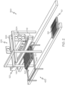
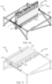
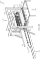
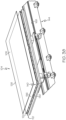
- the carrier transfer device 110 includes, or takes the form of, a mobile platform that supports the ply carrier 104 and moves the ply carrier 104 into position relative to the transfer apparatus 400 and/or the transfer end effector 302, as illustrated in Fig. 1 and 2 .
- the ply carrier 104 includes a base plate 124 and a film 126 that is positioned on the base plate 124.
- the film 126 forms the ply support surface 108.
- the ply carrier 104 may not include the film 126.
- the base plate 124 forms the ply support surface 108.
- the base plate 124 provides a support structure for fabrication of the composite ply 106.
- the base plate 124 is relatively thin and substantially planar or at least has a substantially planar surface to which the film 126 is coupled or that forms the ply support surface 108.
- the base plate 124 is made of a flexible material.
- the base plate 124 is made of a resilient material.
- the base plate 124 facilities transfer and application of the composite ply 106 to the forming tool 120.
- the base plate 124 is capable of deforming during application (e.g., stamping) of the composite ply 106 to the forming tool 120 and then returning to its original (e.g., substantially planar) shape.
- the base plate 124 is reusable for application of a number of composite plies 106, thereby reducing equipment and material costs.
- the base plate 124 is made of a metallic material.
- the base plate 124 includes, or takes the form of, a metal sheet, such as a sheet of spring steel.
- the base plate 124 may be made of any other suitable material.
- the base plate 124 is made of a material that is sufficiently flexible and resilient to enable contouring of the base plate 124 during application of the composite ply 106 to the forming tool 120.
- the film 126 provides a contact surface onto which the composite ply 106 is supported.
- composite material is laid up on the film 126 during fabrication of the composite ply 106.
- the film 126 is a relatively thin and flexible sheet of material that covers the base plate 124.
- the film 126 facilities fabrication of the composite ply 106 and application and formation of the composite ply 106 over the forming tool 120.
- the film 126 provides a work surface to which the composite ply 106 is formed and/or temporarily held.
- the film 126 is capable of deforming during application and formation of the composite ply 106 over the forming tool 120.
- the film 126 is also capable of being removed from the composite ply 106, after formation of the composite ply 106 over the forming tool 120.
- movement of the magnetic chuck 310 relative to the transfer frame 314 along the first movement axis 352 in a first direction places the magnetic-chuck contact surface 318 in contact with the composite ply 106, supported by the ply carrier 104, for magnetic engagement with the ply carrier 104.
- Movement of the magnetic chuck 310 relative to the transfer frame 314 along the first movement axis 352 in a second direction, opposite to the first direction, moves the magnetic-chuck contact surface 318, magnetically engaged with the ply carrier 104, away from the carrier transfer device 110 for removal of the ply carrier 104 from the carrier transfer device 110.
- the placement end effector 304 is positioned to engage the base plate 124 of the ply carrier 104.
- the placement end effector 304 is moved toward the transfer end effector 302 and, thus, the ply carrier 104, supporting the composite ply 106, such that the placement end effector 304 engages the base plate 124.
- the placement end effector 304 includes a vacuum chuck 312.
- the vacuum chuck 312 is configured to selectively apply a retention vacuum to the base plate 124 for removal of the ply carrier 104 from the transfer end effector 302 by the placement end effector 304.
- the vacuum chuck 312 is further configured to selectively remove the retention vacuum from the base plate 124 for removal of the composite ply 106 from the ply carrier 104 during application of the composite ply 106 on the forming tool 120 ( Figs. 1 and 2 ).
- the film 126 is releasably coupled to the base plate 124 via vacuum retention during removal of the ply carrier 104 from the transfer end effector 302 and application of the composite ply 106 on the forming tool 120 by the placement end effector 304.
- the base plate 124 facilitates vacuum to move through the base plate 124 and engage the film 126.
- the vacuum table 344 is configured to selectively apply the retention vacuum to select portions of the ply carrier 104. Selective application of the retention vacuum temporarily holds the base plate 124 on the placement end effector 304 during removal of the ply carrier 104 from the transfer end effector 302 and application of the composite ply 106 on the forming tool 120. Selective application of the retention vacuum temporarily holds the film 126 and, thus, the composite ply 106 on the base plate 124 during removal of the ply carrier 104 from the transfer end effector 302 and application of the composite ply 106 on the forming tool 120.
- the placement end effector 304 includes parts and components (e.g., vacuum source, vacuum ports, plumbing, actuators, valves and the like) that enable production, application and selective control of the retention vacuum.
- the vacuum source e.g., a vacuum pump
- the vacuum source may be component of the system 300 or a component of the placement apparatus 402.
- the vacuum source may be an integral component of the placement end effector 304.
- the retention vacuum is provided by the vacuum table 344, which is then applied to the film 126 through the plurality of vacuum apertures 128 formed in the base plate 124.
- the ply carrier 104 also includes a liner 136.
- the liner 136 is coupled to the base plate 124.
- the liner 136 is a relatively thin sheet of material that covers the base plate 124.
- the liner 136 is coupled to and covers the surface of the base plate 124 and is located between the base plate 124 and the film 126.
- the liner 136 may be coupled to the base plate 124 in any one of various techniques, such as via adhesive bonding, mechanical fasteners and the like.
- the film 126 is positioned on the liner 136 and the liner 136 provides a contact surface onto which the film 126 is applied.
- the vacuum chuck 312 is movable relative to the placement frame 342 to position the vacuum-chuck contact surface 346 in contact with the ply carrier 104, supporting the composite ply 106, for removal of the ply carrier 104 from the transfer end effector 302 by the placement end effector 304.
- the vacuum chuck 312 is movable relative to the placement frame 342 to position the ply carrier 104 for application of the composite ply 106 to the forming tool 120 ( Figs. 1 and 2 ) by the placement end effector 304.
- the placement frame 342 may include any rigid structure, formed by one or more structural and/or nonstructural frame members.
- the placement frame 342 provides support to the vacuum chuck 312.
- the placement end effector 304 may also include one or more joints, couplings and drive components (e.g., motors, actuators, etc.) configured to move the vacuum chuck 312 in one or more linear directions and/or rotational orientations relative to the transfer frame 314.
- the vacuum chuck 312 is linearly moveable along a second movement axis 390 relative to the placement frame 342 for hand-off and application of the ply carrier 104 by the placement end effector 304. In one or more examples, the vacuum chuck 312 is pivotable about a pivot axis 340 relative to the placement frame 342 to orient the ply carrier 104 for application of the composite ply 106 to the forming tool 120 by the placement end effector 304.
- the placement end effector 304 includes a placement actuator 392.
- the placement actuator 392 is coupled to the placement frame 342 and to the vacuum chuck 312.
- the placement actuator 392 is configured to selectively drive and control movement of the vacuum chuck 312 relative to the placement frame 342 along the second movement axis 390 and/or about the pivot axis 340.
- the placement end effector 304 includes a plurality of placement actuators 392, for example, at least one placement actuator 392 configured to linearly move the vacuum chuck 312 along the second movement axis 390 and at least one placement actuator 392 configured to pivot the vacuum chuck 312 about the pivot axis 340.
- the placement actuator 392 may include any one of various suitable types of selectively controlled actuators.
- the placement actuator 392 may include, or take the form of, a linear actuator or a rotary actuator, such as a pneumatic actuator, an electro-mechanical actuator, a power screw and nut mechanism, a rack and pinion mechanism and the like.
- movement of the vacuum chuck 312 relative to the placement frame 342 along the second movement axis 390 in a first direction places the vacuum-chuck contact surface 346 in contact with the base plate 124 of the ply carrier 104 for vacuum engagement with the ply carrier 104.
- Movement of the vacuum chuck 312 relative to the placement frame 342 along the second movement axis 390 in a second direction, opposite to the first direction, moves the vacuum-chuck contact surface 346, engaged via vacuum with the ply carrier 104, away from the transfer end effector 302 for removal of the ply carrier 104 from the transfer end effector 302.
- movement of the vacuum chuck 312 relative to the placement frame 342 along the second movement axis 390 in the first direction places the composite ply 106 in contact with the forming tool 120.
- Movement of the vacuum chuck 312 relative to the placement frame 342 along the second movement axis 390 in the second direction, opposite to the first direction, moves the base plate 124 of the ply carrier 104, released from the composite ply 106, away from the forming tool 120 after application of the composite ply 106 on the forming tool 120.
- movement of the vacuum chuck 312 relative to the placement frame 342 about the pivot axis 340 orients the ply carrier 104, and the composite ply 106 held on the ply carrier 104, relative to a forming surface 118 ( Figs. 1 and 2 ) of the forming tool 120 for application of the composite ply 106.
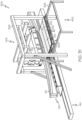
- the system 300 includes a placement support platform 308.
- the placement support platform 308 may be a component of, or may form a part of, the placement apparatus 402.
- the placement frame 342 of the placement end effector 304 is coupled to the placement support platform 308.
- the placement end effector 304 is movable relative to the placement support platform 308 to remove the ply carrier 104 from the transfer end effector 302.
- the placement end effector 304 is movable relative to the placement support platform 308 to position the ply carrier 104 for application of the composite ply 106 to the forming tool 120 by the placement end effector 304.
- the placement support platform 308 may include any rigid structure, formed by one or more structural and/or nonstructural frame members.
- the placement support platform 308 may also include one or more joints, couplings and drive components (e.g., motors, actuators, etc.) configured to move the placement end effector 304 in one or more linear directions and/or orient the placement end effector 304 in a plurality of rotational orientations relative to the placement support platform 308.
- the vacuum chuck 312 includes a vacuum-chuck support member 356.
- the vacuum-chuck support member 356 is coupled to and is movable relative to the placement frame 342.
- the vacuum table 344 is coupled to the vacuum-chuck support member 356.
- the placement actuator 392 is arranged between and is coupled to the placement frame 342 and the vacuum-chuck support member 356 and is further configured to move the vacuum-chuck support member 356 along the second movement axis 390 and/or about the pivot axis 340 relative to the placement frame 342.
- the vacuum-chuck support member 356 provides a support structure for the vacuum table 344.
- the vacuum-chuck support member 356 is rigid and provides a support structure to which the vacuum table 344 is coupled.
- the vacuum chuck 312 includes a vacuum-chuck pliable member 358.
- the vacuum-chuck pliable member 358 is coupled to the vacuum table 344, opposite the vacuum-chuck support member 356.
- the vacuum-chuck pliable member 358 is permeable by the retention vacuum.
- the vacuum-chuck pliable member 358 forms the vacuum-chuck contact surface 346.
- the vacuum-chuck pliable member 358 provides a cushion for contact with the base plate 124 of the ply carrier 104 during hand-off of the ply carrier 104 from the transfer end effector 302 and application of composite ply 106 on the forming tool 120.
- the vacuum-chuck pliable member 358 is substantially planar or at least has a substantially planar surface for contact with the ply carrier 104.
- the magnetic-chuck pliable member 330 may be made of any suitable material, including, but not limited to, foam and the like.
- the vacuum-chuck pliable member 358 includes a plurality of vacuum apertures 394.
- the vacuum chuck 312 e.g., the vacuum table 3414 is configured to apply the retention vacuum through the plurality of vacuum apertures 394 of the vacuum-chuck pliable member 358 to retain base plate 124 of the ply carrier 104 on the vacuum-chuck pliable member 358 and to retain the film 126 ( Fig. 17 ) on the base plate 124.
- the vacuum-chuck pliable member 358 is otherwise permeable by the retention vacuum.
- the vacuum chuck 312 includes the plurality of vacuum cups 360.
- the vacuum cups 360 are configured to apply the retention vacuum to the ply carrier 104 during hand-off of the ply carrier 104 and placement of the composite ply 106 on the forming tool 120.
- surfaces of the vacuum cups 360 form the vacuum-chuck contact surface 346.
- the vacuum cups 360 are coupled to and in fluid communication with the vacuum table 344, such as coupled to the vacuum ports 386.
- each one of the vacuum cups 360 is mounted on vacuum table 344 via a standoff.
- the vacuum cups 360 form a part of the vacuum table 344, such as replacing the plurality of vacuum ports 386 and/or vacuum zones 382.
- the vacuum cups 360 are coupled to the vacuum-chuck support member 356 and are coupled to and in fluid communication with the vacuum source. As such a particular operating configuration of the vacuum table 344 and the vacuum cups 360 is not intended to be limiting and configurations other than those described and illustrated are also contemplated.
- each one of or sets of the vacuum cups 360 are controllable to selectively apply or remove vacuum to a corresponding set of the vacuum apertures 128 of the base plate 124 ( Fig. 17 ) positioned over the respective vacuum cup 360.
- each one of or sets of the vacuum cups 360 are operatively coupled to a corresponding valve 384 ( Fig. 20 ) that is selectively open or closed to control application of vacuum to one or more respective vacuum cups 360.
- the vacuum cups 360 enable application of vacuum where needed to retain the base plate 124 of the ply carrier 104 on the vacuum cups 360 and to retain the film 126 on the base plate 124.
- the vacuum cups 360 also enable cessation of vacuum to select areas of the base plate 124, such as during release of the film 126 and the composite ply 106 after application of the composite ply 106 to the forming tool 120 ( Figs. 1 , 2 and 31-34 ).
- the vacuum cups 360 may be arranged to adequately distribute a sufficient retention vacuum to retain base plate 124 on the placement end effector 304 and to retain the film 126 on the surface of the base plate 124 during movement of the ply carrier 104.
- each one of, or at least some of, the vacuum cups 360 are deformable, such as compressible, flexible and the like.
- the vacuum cups 360 may also be resilient such that they can be deformed and return to their original condition.
- the vacuum cup 360 may include, or take the form of, a bellows vacuum cup.
- the vacuum chuck 312 includes a shaping member 362.
- the shaping member 362 is coupled to the vacuum table 344 (or the vacuum-chuck support member 356) and is movable relative to the vacuum table 344 and the plurality of vacuum cups 360.
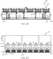
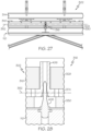
- the shaping member 362 may move linearly between a retracted position (e.g., as shown in Figs. 21-24 ) and an extended position (e.g., as shown in Figs. 25 and 26 ).
- the shaping member 362 may be used to create a curvature in the ply carrier 104 during placement and application of the composite ply 106 on the forming tool 120.
- the shaping member 362 includes a plurality of vacuum-cup openings 364. At least a portion of each one of the plurality of vacuum cups 360 is located within a corresponding one of the plurality of vacuum-cup openings 364 of the shaping member 362.
- the vacuum-cup openings 364 of the shaping member 362 enable the shaping member 362 to move relative to the vacuum cups 360 (e.g., as illustrated in Figs. 21-26 ).
- the vacuum-chuck pliable member 358 coupled to the shaping member 362, opposite the vacuum table 344 (or the vacuum-chuck support member 356).
- the vacuum-chuck pliable member 358 includes a plurality of vacuum-cup openings 396.
- the vacuum-cup opening 396 of the vacuum-chuck pliable member 358 are aligned with and in volumetric communication with a corresponding one of the vacuum-cup openings 364 of the shaping member 362.
- At least a portion of each one of the plurality of vacuum cups 360 is located within a corresponding one of the plurality of vacuum-cup openings 396 of the vacuum-chuck pliable member 358.
- the vacuum-cup openings 396 of the vacuum-chuck pliable member 358 enable the shaping member 362 and the vacuum-chuck pliable member 358 to move relative to the vacuum cups 360 (e.g., as illustrated in Figs. 21-26 ).
- FIGs. 21-26 schematically illustrate examples of the placement end effector 304 during removal of the ply carrier 104 and shaping of the ply carrier 104 before placement of the composite ply 106 on the forming tool 120.
- the shaping member 362 is in the retracted position and the vacuum cups 360 are in an undeformed state.
- the placement end effector 304 is moved to place the vacuum-chuck contact surface 346 (e.g., surfaces of the vacuum cups 360) in contact with the base plate 124 of the ply carrier 104.
- the retention vacuum is applied to the base plate 124 of the ply carrier 104 via the vacuum cups 360 to remove the ply carrier 104 and hold the ply carrier 104 on the placement end effector 304.
- Application of the retention vacuum compresses or retracts the vacuum cups 360 (e.g., as shown in Fig. 24 ). In one or more examples, vacuum cups 360 compress or retract substantially equally thus maintaining the ply carrier 104 in a substantially planar configuration.
- the forming tool 120 may have a complex shape or a portion of the forming surface 118 may have a curvature. Controlling the curvature of (e.g., creating curvature in) the ply carrier 104 and, thus, the composite ply 106 may provide an increase in contact surface area between the composite ply 106 and the forming surface 118 when the composite ply 106 is applied (e.g., stamped) onto the forming tool 120.
- the shaping member 362 includes a shaping surface 366.
- the shaping surface 366 is contoured and is configured to create a contour or curvature in the ply carrier 104.
- the shaping surface 366 may have a contour or a curve along one or more axes.
- the shaping surface 366 is convex (e.g., as illustrated in Figs. 21 , 23 and 25 ).
- the shaping surface 366 is concave.
- the shaping surface 366 may be substantially planar and is configured to maintain the ply carrier 104 in a substantially planar configuration.
- a curvature may be formed in the ply carrier 104 using the shaping member 362.
- the shaping member 362 is moved from the retracted position (e.g., as shown in Figs. 23 and 24 ) to the extended position until the vacuum-chuck contact surface 346 of the vacuum-chuck pliable member 358 is in contact with the base plate 124 of the ply carrier 104.
- the vacuum-chuck pliable member 358 is sandwiched and compressed between the shaping surface 366 and the base plate 124 of the ply carrier 104.
- the shaping member 362 pushes on the ply carrier 104 held by the vacuum cups 360.
- the vacuum chuck 312 includes a shaping actuator 368.
- the shaping actuator 368 is arranged between and is coupled to the vacuum table 344 (or the vacuum-chuck support member 356) and to the shaping member 362.
- the shaping actuator 368 is configured to selectively drive and control movement of the shaping member 362 relative to the vacuum table 344.
- the vacuum chuck 312 includes a plurality of transfer actuators 348, for example, are located around a perimeter of the vacuum table 344 and the shaping member 362.
- the ply hand-off and placement operation utilizes the placement apparatus 402 and, more particularly, the placement end effector 304 to: (1) remove the ply carrier 104 from the transfer end effector 302; (2) reposition and/or reorient the ply carrier 104 for placement of the composite ply 106 on the forming tool; and (3) apply the composite ply 106 to the forming tool 120.
- the composite ply 106 adheres to a portion of the forming surface 118 via the resin matrix.
- the vacuum chuck 312 then selectively removes the retention vacuum from a select portion of the ply carrier 104 to release the film 126 and, thus, the composite ply 106.
- the composite ply 106 adheres to a portion of the forming surface 118 via the resin matrix.
- the placement end effector 304 is then moved away from the forming tool 120 to remove the empty ply carrier 104.
- the transfer end effector 302 includes a first portion of the first indexing device 316 that is configured to cooperate with a second portion of the first indexing device 316 located on the carrier transfer device 110. Alignment and engagement of the first portion and the second portion of the first indexing device 316 enables indexing of the magnetic chuck 310 relative to the carrier transfer device 110 during the pick-up operation for removal of the ply carrier 104 from the carrier transfer device 110 by the transfer end effector 302.
- the first portion of the first indexing device 316 includes, or takes the form of, a pin receiver 406.
- the second portion of the first indexing device 316 includes, or takes the form of, a locating pin 408.
- the pin receiver 406 is coupled to the magnetic chuck 310, such as to the magnetic-chuck support member 328.
- the locating pin 408 is coupled to and projects from the carrier transfer device 110.
- the pin receiver 406 is configured to receive the locating pin 408 when the transfer end effector 302 moves into position to remove the ply carrier 104 from the carrier transfer device 110.
- the magnetic-chuck pliable member 330 may include a pin opening that is aligned with the pin receiver 406 such that the locating pin 408 can pass through the magnetic-chuck pliable member 330.
- the transfer end effector 302 includes a first portion of the second indexing device 338.
- the placement end effector 304 includes a second portion of the second indexing device 338.
- the first portion and the second portion of the second indexing device 338 are configured to cooperate. Alignment and engagement of the first portion and the second portion of the second indexing device 338 enables indexing of the placement end effector 304 relative to the transfer end effector 302 during the hand-off operation for removal of the ply carrier 104 from the transfer end effector 302 by the placement end effector 304.
- the first portion of the second indexing device 338 includes, or takes the form of, the pin receiver 406.
- the second portion of the second indexing device 338 includes, or takes the form of, the locating pin 408.
- the pin receiver 406 is coupled to the magnetic chuck 310, such as to the magnetic-chuck support member 328.
- the locating pin 408 is coupled to and projects from the vacuum chuck 312, such as the vacuum table 344 or the vacuum-chuck support member 356.
- the pin receiver 406 is configured to receive the locating pin 408 when the placement end effector 304 moves into position to remove the ply carrier 104 from the transfer end effector 302.
- the magnetic-chuck pliable member 330 may include a pin opening that is aligned with the pin receiver 406 such that the locating pin 408 can pass through the magnetic-chuck pliable member 330.
- the first portion of the first indexing device 316 and the first portion of the second indexing device 338 are the same component of the transfer end effector 302.
- the pin receiver 406 of the magnetic chuck 310 is configured to receive the locating pin 408 of the carrier transfer device 110 during pick-up and to receive the locating pin 408 of the placement end effector 304 during hand-off.
- system 300 may include a plurality of (e.g., at least two) first indexing devices 316 to properly index the transfer end effector 302 relative to the carrier transfer device 110 and a plurality of (e.g., at least two) second indexing devices 338 to properly index the placement end effector 304 relative to the transfer end effector 302.
- a plurality of (e.g., at least two) first indexing devices 316 to properly index the transfer end effector 302 relative to the carrier transfer device 110
- second indexing devices 338 to properly index the placement end effector 304 relative to the transfer end effector 302.
- the system 300 may also be configured to accommodate and correct for slight misalignment during an indexing of the transfer end effector 302 to the carrier transfer device 110 using the first indexing device 316 and during an indexing of placement end effector 304 to the transfer end effector 302 using the second indexing device 338.
- the magnetic chuck 310 is configured to move relative to the transfer frame 314 along a float axis 354.
- the float axis 354 is approximately perpendicular to the first movement axis 352 ( Fig. 3 ).
- the transfer actuators 348 and the transfer guides 350 of the transfer end effector 302 have a small degree of free movement and are configured to enable movement of the magnetic chuck 310 relative to the transfer frame 314 along the float axis 354. Movement of the magnetic chuck 310 relative to the transfer frame 314 along the float axis 354 facilitates indexing of the transfer end effector 302 relative to the carrier transfer device 110. Movement of the magnetic chuck 310 relative to the transfer frame 314 along the float axis 354 also facilitates indexing of the transfer end effector 302 relative to the placement end effector 304.
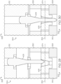
- the first indexing device 316 ( Figs. 27 and 28 ) and the second indexing device 338 ( Figs. 29 and 30 ) are configured to urge movement of the magnetic chuck 310 relative to the transfer frame 314 during indexing.
- the pin receiver 406 includes a conical opening for receiving the locating pin 408 and that forms a conical indexing surface. As best illustrated in Fig. 29 , if a slight misalignment is present upon initially locating the transfer end effector 302, the locating pin 408 engages a portion of the conical indexing surface.
- the locating pin 408 applies a force on the conical indexing surface and the magnetic chuck 310 moves along the float axis 354 in response to the force to coaxially align the pin receiver 406 and the locating pin 408, as best illustrated in Figs. 28 and 30 .
- FIG. 35 which illustrates an example of the method 1200 of placing the composite ply 106. Implementations of the method 1200 are performed using the system 300, as illustrated in Figs. 1-34 .
- the method 1200 includes a step of (block 1202) magnetically engaging the ply carrier 104, supporting the composite ply 106.
- the carrier transfer device 110 is loaded with the ply carrier 104, supporting the composite ply 106 (e.g., as shown in Fig. 38 ).
- the carrier transfer device 110 and the transfer end effector 302 are positioned relative to each other for pick-up and removal of the ply carrier 104 (e.g., as shown in Fig. 6 ).
- the magnetic chuck 310 indexes and moves into contact with the ply carrier 104 and/or the composite ply 106, supported on the ply carrier 104 (e.g., as shown in Figs. 27 and 28 ).
- the magnetic-chuck actuator 324 positions the magnets 320 into magnetic engagement with the base plate 124 of the ply carrier 104 (e.g., as shown in Figs. 7-9 ).
- the method 1200 includes a step of (block 1204) reorienting the ply carrier 104.
- transfer end effector 302 picks up and removes (e.g., lifts off) the ply carrier 104 and the composite ply 106, supported on the ply carrier 104, from the carrier transfer device 110.
- the transfer end effector 302 rotates about the rotation axis 322 to flip the ply carrier 104 over such that the base plate 124 is accessible by the placement end effector 304 (e.g., as shown in Figs. 10, 11 , 31 and 33 ).
- the method 1200 includes a step of (block 1206) applying the retention vacuum to the ply carrier 104.
- the transfer end effector 302 and the placement end effector 304 are positioned relative to each other for hand-off of the ply carrier 104 (e.g., as shown in Figs. 31 and 33 ).
- the vacuum chuck 312 indexes and moves into contact with the base plate 124 of the ply carrier 104 (e.g., as shown in Figs. 13 , 29 and 30 ).
- the vacuum chuck 312 applies the retention vacuum to the ply carrier 104 using the vacuum table 344 or the plurality of vacuum cups 360.
- the method 1200 includes a step of (block 1208) magnetically disengaging the ply carrier 104.
- the magnetic-chuck actuator 324 positions the magnets 320 into magnetic disengagement from the base plate 124 of the ply carrier 104 (e.g., as shown in Figs. 7-9 ).
- the placement end effector 304 picks up and removes (e.g., lifts off) the ply carrier 104 and the composite ply 106, supported on the ply carrier 104, from the transfer end effector 302.
- the method 1200 includes a step of (block 1210) applying the composite ply 106 to the forming tool 120.
- the placement end effector 304 is positioned relative to the forming tool 120 for placement (e.g., application) of the ply carrier 104 (e.g., as shown in Figs. 32 and 34 ).
- the placement end effector 304 moves the composite ply 106 into contact with the forming surface 118 of the forming tool 120 and presses (e.g., stamps) the ply carrier 104 and, thus, the composite ply 106 against the forming surface 118.
- the configuration of the vacuum chuck 312, such as use of the vacuum table 344 or the vacuum cups 360, may depend on various manufacturing factors, such as the type of composite structure 102 ( Fig. 36 ) being fabricated, the size and/or shape of the composite ply 106, the type and/or geometry of the forming tool 120 and the like.
- the vacuum table 344 may be used to place the composite ply 106 on the forming tool 120 where a portion of the forming surface 118 on which the composite ply 106 is placed is generally planar (e.g., as shown in Fig. 34 ).
- the vacuum cups 360 may be used to place the composite ply 106 on the forming tool 120 where a portion of the forming surface 118 on which the composite ply 106 is placed is contoured (e.g., as shown in Fig. 32 ).
- the method 1200 includes a step of forming a curvature in the ply carrier 104 and, thus, the composite ply 106 using the shaping member 362.
- the shape of the contour and/or the degree of curvature formed using the shaping member 362 may depend on various factors, such as the type of composite structure 102 ( Fig. 36 ) being fabricated, the size and/or shape of the composite ply 106, the type and/or geometry of the forming tool 120 and the like.
- the step of forming the curvature is performed before the step of (block 1210) applying the composite ply 106 to the forming tool 120.
- the method 1200 includes a step of (block 1212) ceasing the retention vacuum to a select portion of the ply carrier 104.
- the composite ply 106 is tacked to the forming tool 120 via the resin matrix.
- the vacuum chuck 312 selectively ceases (e.g., removes) the retention vacuum from a select portion of the ply carrier 104 to release the film 126, and the composite ply 106 attached (e.g., adhered via the resin matrix) to the film 126, from the base plate 124, while selectively applying (e.g., maintaining) the retention vacuum to a select different portion of the ply carrier 104 to hold the base plate 124 on the vacuum chuck 312.
- the method 1200 includes a step of (block 1214) releasing the composite ply 106 from the ply carrier 104.
- the placement end effector 304 moves away from the forming tool 120 keeping the ply carrier 104 (e.g., the base plate 124) and leaving the composite ply 106, with the attached film 126, on the forming tool 120.
- the method 1200 includes a step of returning the ply carrier 104.
- the transfer end effector 302 and the placement end effector 304 are positioned relative to each other for hand-off of the ply carrier 104 back to the transfer end effector 302.
- the magnetic-chuck actuator 324 positions the magnets 320 into magnetic engagement with the base plate 124 of the ply carrier 104.
- the vacuum chuck 312 selectively ceases (e.g., removes) the retention vacuum from the ply carrier 104 to release the ply carrier 104.
- the carrier transfer device 110 and the transfer end effector 302 are positioned relative to each other for return of the ply carrier 104 to the carrier transfer device 110.
- the carrier transfer device 110 is re-loaded with another composite ply 106, supported on the ply carrier 104.
- the operations described above are repeated a number of times to transfer and place any number of composite plies 106.
- the present disclosure is further directed to a system for fabricating a composite structure (referred to herein as "system" 100).
- system 100 a system for fabricating a composite structure
- Fig. 42 by way of examples, the present disclosure is additionally directed to a method of fabricating a composite structure.
- the present disclosure is also directed to a composite structure 102 fabricated using the system 300 and/or the system 100 or according to the method 1200 and/or the method 1000.
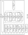
- the system 100 includes a plurality of sub-systems that facilitate and correspond to different fabrication operations associated with the manufacture of the composite structure 102.
- the sub-systems of the system 100 are interlinked and cooperate to automate at least a portion of the fabrication process.
- the sub-systems of the disclosed system 100 may be referred to as "systems" themselves or stations in which one or more fabrication operations occur.
- the examples of the system 100 and method 1000 described herein utilize the plurality of semi-automated or automated sub-systems to perform ply-by-ply formation and compaction of individual composite plies 106 on the forming tool 120.
- Ply-by-ply formation refers to the laydown of composite plies 106 on the forming tool 120 in a predetermined sequence and/or predetermined ply angle, and the composite plies 106 are compacted onto the forming tool 120 individually after each composite ply 106 is laid down, or after more than one composite ply 106 had been laid down.
- the system 100 includes a lamination system 112 (e.g., laminating sub-system or station), the transfer and placement system 300, also referred to herein generally as a transfer system or a placement system (e.g., transfer and placement sub-system or station) and a forming system 122 (e.g., forming sub-system or station).
- the system 100 also includes a trim system 114 (e.g., trim sub-system or station) and a scrap removal system 142 (e.g., a scrap removal sub-system of station).
- the system 100 further includes a film removal system 160 (e.g., film removal sub-system or station).
- the system 100 additionally includes a carrier preparation system 162 (e.g., carrier preparation sub-system or station).
- the system 100 also includes a positioning system 144 (e.g., positioning sub-system).
- the vacuum table 130 is in fluid communication with the plurality of vacuum apertures 128.
- the vacuum table 130 includes a perforated top and a vacuum chamber that is in fluid communication with a vacuum source.
- the vacuum table 130 is configured to apply a retention vacuum to the plurality of vacuum apertures 128 of the base plate 124 to temporarily hold and retain the film 126 on the base plate 124.
- the carrier transfer device 110 includes parts and components (e.g., vacuum source, vacuum ports, plumbing, actuators, valves and the like) that enable production, application and selective control of the retention vacuum.
- the vacuum source e.g., a vacuum pump
- the vacuum source may be component of the system 100 or a part of a sub-system (e.g., the positioning system 144) of the system 100.
- the vacuum source may be an integral component of the carrier transfer device 110.
- the retention vacuum is provided by the vacuum table 130, which is then applied to the film 126 through the plurality of vacuum apertures 128 formed in the base plate 124.
- the vacuum table 130 includes a plurality of vacuum zones 204.
- Each one of the plurality of vacuum zones 204 is controllable to selectively apply and remove vacuum to a corresponding set of vacuum apertures 128 ( Fig. 41 ) positioned over the respective vacuum zone 204.
- each one of the plurality of vacuum zones 204 includes a valve 206 that is selectively open or closed to control application of vacuum to the respective vacuum zone 204.
- the vacuum zones 204 enable the vacuum table 130 to apply vacuum where needed to retain the film 126 on the base plate 124.
- the vacuum zones 204 also enable the vacuum table 130 to cease application of vacuum to select areas of the base plate 124, such as during removal of scrap remnants of the composite ply 106 after a trimming operation.
- the vacuum table 130 and the plurality of vacuum apertures 128 formed in the base plate 124 are arranged to adequately distribute a sufficient retention vacuum to retain the film 126 on the surface of the base plate 124 during movement of the ply carrier 104 through the system 100.
- the vacuum table 130 includes a plurality of lip seals 208.
- Each lip seal 208 is located between adjacent ones of the plurality of vacuum zones 204.
- the lip seals 208 form the peripheral boundaries of the vacuum zones 204 and isolate each one of the vacuum zones 204 from an adjacent one of the vacuum zones 204.
- the plurality of lip seals 208 provide a sealing interface with the base plate 124 without affecting the surface flatness of the vacuum table 130.
- the system 100 includes an indexing structure 140.
- the indexing structure 140 is configured to operatively locate the ply carrier 104 at a specified location on the carrier transfer device 110.
- the indexing structure 140 includes mating components located on the carrier transfer device 110 and the base plate 124 of the ply carrier 104.
- the carrier transfer device 110 includes at least one indexing pin 200 (e.g., at least two indexing pins 200) and the base plate 124 includes at least one indexing aperture 202 (e.g., at least two indexing apertures 202) that corresponds to the indexing pin 200.
- the indexing pin 200 and the indexing aperture 202 cooperate to position the ply carrier 104 on the carrier transfer device 110.
- the sub-systems of the system 100 are generally arranged in operational sequence with each other within a manufacturing environment.
- the lamination system 112 is in sequential relation to the carrier preparation system 162.
- the trim system 114 is in sequential relation to the lamination system 112.
- the scrap removal system 142 is in sequential relation to the trim system 114.
- the transfer and placement system 300 is in sequential relation to the scrap removal system 142.
- the forming system 122 is in sequential relation to the transfer and placement system 300.
- the film removal system 160 is in sequential relation to the forming system 122.
- the carrier preparation system 162, the trim system 114 and/or the scrap removal system 142 may not be utilized in fabrication of the composite structure 102 and, thus, may not be included as a sub-system within the system 100.
- the transfer and placement system 300 is in sequential relation to the lamination system 112.
- the carrier transfer device 110 conveys the ply carrier 104 to the carrier preparation system 162 for preparation of the ply carrier 104. In one or more examples, the carrier transfer device 110 coveys the ply carrier 104 from the carrier preparation system 162 to the lamination system 112 for application of the composite ply 106 to the ply carrier 104. In one or more examples, the carrier transfer device 110 conveys the ply carrier 104, and the composite ply 106 supported on the ply carrier 104, from the lamination system 112 to the trim system 114 for cutting the composite ply 106.
- the carrier transfer device 110 conveys the ply carrier 104, and the composite ply 106 supported on the ply carrier 104, from the trim system 114 to the scrap removal system 142 for removal of remnants (e.g., scrap composite material) from the ply carrier 104 after cutting.
- the carrier transfer device 110 conveys the ply carrier 104, and the composite ply 106 supported on the ply carrier 104, from the trim system 114 to the transfer and placement system 300 for application of the composite ply 106 to the forming tool 120.
- the tool transfer device 146 conveys the forming tool 120 to the transfer and placement system 300 for application of the composite ply 106 to the forming tool 120. In one or more examples, the tool transfer device 146 conveys the forming tool 120, and the composite ply 106 applied to the forming tool 120, from the transfer and placement system 300 to the forming system 122 for formation and compaction of the composite ply 106 over the forming tool 120. In one or more examples, the tool transfer device 146 conveys the forming tool 120, and the composite ply 106 formed over the forming tool 120, from the forming system 122 to the film removal system 160 for removal of the film 126 from the composite ply 106.
- the positioning system 144 may be any suitable system that guides the carrier transfer device 110 and the tool transfer device 146 along a predetermined workflow or path.
- the positioning system 144 is configured to selectively position the carrier transfer device 110 relative to individual sub-systems or workstations of the system 100 (e.g., the carrier preparation system 162, the lamination system 112, the trim system 114, the scrap removal system 142 and the transfer and placement system 300).
- the positioning system 144 is configured to selectively position the tool transfer device 146 relative to individual sub-systems or workstations of the system 100 (e.g., the transfer and placement system 300, the forming system 122 and the film removal system 160).
- the positioning system 144 includes a rail assembly 168 or similar conveyor assembly that physically guides the carrier transfer device 110 and the tool transfer device 146 through the system 100.
- the carrier transfer device 110 and the tool transfer device 146 may include a cart, a pallet, a carriage, or similar platform that is configured to travel along the rail assembly 168.
- the positioning system 144, the carrier transfer device 110 and the tool transfer device 146 include cooperating parts and components (e.g., drive motors, tracks, actuators, gears, wheels, sensors and the like) that enable selectively controlled transportation of the carrier transfer device 110 and the tool transfer device 146 along the positioning system 144.
- the positioning system 144 includes a linear carrier guide.
- the linear carrier guide is configured to operatively translate the carrier transfer device 110 through the sub-systems or workstations of the system 100, for example, along a linear workflow path.
- a portion of rail assembly 168 dedicated to conveying the carrier transfer device 110 is a linear segment with discrete terminal ends.
- the positioning system 144 includes a linear tool guide.
- the linear tool guide is configured to operatively translate the tool transfer device 146 through the sub-systems or workstations of the system 100, for example, along a linear workflow path.
- a portion of rail assembly 168 dedicated to conveying the tool transfer device 146 is a linear segment with discrete terminal ends.
- the positioning system 144 includes a closed-loop carrier guide.
- the closed-loop carrier guide is configured to operatively circulate the carrier transfer device 110 through the sub-systems or workstations of the system 100, for example, along a continuous workflow path.
- a portion of rail assembly 168 dedicated to conveying the carrier transfer device 110 is a continuous loop.
- the positioning system 144 includes a closed-loop tool guide.
- the closed-loop tool guide is configured to operatively circulate the tool transfer device 146 through the sub-systems or workstations of the system 100, for example, along a continuous workflow path.
- a portion of rail assembly 168 dedicated to conveying the tool transfer device 146 is a continuous loop.
- the positioning system 144 includes access areas that enable on-loading and off-loading of the carrier transfer device 110 and the tool transfer device 146.
- the system 100 utilizes a plurality of carrier transfer devices 110.
- Each one of the plurality of carrier transfer devices 110 conveys a respective one of a plurality of ply carriers 104 through the system 100.
- the system 100 utilizes a plurality of tool transfer devices 146.
- Each one of the plurality of tool transfer devices 146 conveys a respective one of a plurality of forming tool 120 through the system 100.
- multiple operations can be performed simultaneously on different ones of the plurality of forming tools 120, thereby reducing cycle time.
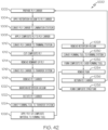
- Fig. 41 illustrates an example of the method 1000 that utilizes the system 100 (e.g., shown in Figs. 36 and 37 ) to fabricate the composite structure 102.
- the method 1000 includes a step of (block 1002) preparing the ply carrier 104 using the carrier preparation system 162.
- the method 1000 includes a step of (block 1004) selectively applying the retention vacuum to retain the film 126 on the base plate 124 using the carrier transfer device 110.
- the method 1000 includes a step of (block 1006) conveying the ply carrier 104 to the lamination system 112 using the carrier transfer device 110.
- the method 1000 includes a step of (block 1008) selectively applying the composite ply 106 to the ply support surface 108 of the ply carrier 104 using the lamination system 112.
- the method 1000 includes a step of (block 1024) conveying the forming tool 120 to the transfer and placement system 300 using the tool transfer device 146.
- the method 1000 includes a step of (block 1026) applying the composite ply 106 to at least a portion of the forming surface 118 of the forming tool 120 using the placement apparatus 402 of the transfer and placement system 300.
- the ply carrier 104 is positioned at a predefined location along the forming tool 120 according to the predetermined ply laydown sequence.
- the ply carrier 104 is oriented such that the composite ply 106 is parallel to at least a portion of the forming surface 118 of the forming tool 120.
- the ply carrier 104 is pressed on the forming tool 120 to compress the composite ply 106 against a portion of the forming surface 118 of the forming tool 120.
- the ply carrier 104 may deform when pressed against the forming tool 120, thereby enabling the composite ply 106 to be applied to a greater portion of the contoured forming surface 118.
- the method 1000 includes a step of releasing the film 126 from the base plate 124 and a step of removing the ply carrier 104 (e.g., the base plate 124) from the forming tool 120 using the placement apparatus 402 of the transfer and placement system 300, after the step of (block 1026) applying the composite ply 106 to at least a portion of the forming surface 118 of the forming tool 120.
- the method 1000 includes a step of (block 1028) selectively removing the retention vacuum to release the film 126 from the base plate 124 while retaining the base plate 124 using the placement apparatus 402 of the transfer and placement system 300.
- the composite ply 106 is coupled (e.g., adhered or tacked) to the forming surface 118 and the film 126 remains coupled (e.g., adhered or tacked) to the composite ply 106 by the resin matrix of the composite ply 106.
- the method 1000 includes a step of (block 1030) conveying the forming tool 120 from the transfer and placement system 300 to the forming system 122 using the tool transfer device 146.
- the method 1000 includes a step of (block 1032) forming the composite ply 106 over the at least a portion of the forming surface 118 of the forming tool 120 using the forming system 122.
- the method 1000 includes a step of (block 1034) removing the film 126 from the composite ply 106 using the film removal system 160.
- the step of (block 1034) removing the film 126 is preformed after the step of (block 1032) forming the composite ply 106.
- the method 1000 includes a step of (block 1036) returning the ply carrier 104 (e.g., the base plate 124) to the carrier transfer device 110 using the transfer and placement system 300.
- the step of (block 1036) returning the ply carrier 104 is performed after the step of (block 1026) applying the composite ply 106 to the forming tool 120.
- the above operations are repeated a number of times to fully form the composite structure 102 (block 1038), at which point the process terminates.
- a plurality of composite plies 106 are sequentially fabricated and applied to and formed over the forming tool 120 according the ply-by-ply laydown sequence. For example, a first one of the plurality of composite plies 106 is applied to and is formed over a first portion of the forming tool 120. During a second iteration of the above process, a second one of the plurality of composite plies 106 is applied to and is formed over a second portion of the forming tool 120. This iterative process is repeated until the composite structure 102 is formed.
- the forming tool 120 may be simultaneously located at the transfer and placement system 300 and the forming system 122.
- the first portion of the forming tool 120 may be conveyed to the transfer and placement system 300 for application of the first one of the plurality of composite plies 106.
- the first portion of the forming tool 120 may then be conveyed to forming system 122 while a second portion of the forming tool 120 is conveyed to the transfer and placement system 300.
- the second one of the composite plies 106 may be applied to the second portion of the forming tool 120 while the first one of the composite plies 106 is being formed over the forming tool 120.
- the step of (block 1026) applying the second one of the composite plies 106 and the step of (block 1032) forming the first one of the composite plies 106 are performed simultaneously, thereby reducing cycle time.
- the steps of conveying the ply carrier include a step of operatively translating the carrier transfer device 110 between the carrier preparation system 162, the lamination system 112, the trim system 114 (when applicable), the scrap removal system 142 (when applicable) and the transfer and placement system 300.
- the steps of conveying the ply carrier include a step of operatively circulating the carrier transfer device 110 through the carrier preparation system 162, the lamination system 112, the trim system 114 (when applicable), the scrap removal system 142 (when applicable) and the transfer and placement system 300.
- the steps of conveying the forming tool 120 include a step of operatively translating the tool transfer device 146 between the transfer and placement system 300, the forming system 122 and the film removal system 160. In one or more examples, the steps of conveying the forming tool 120 (e.g., blocks 1024 and 1030) include a step of operatively circulating the tool transfer device 146 through the transfer and placement system 300, the forming system 122 and the film removal system 160.
- the system 100 includes a controller 158.
- the controller 158 is configured to control operation of the system 100 and/or implement the operational steps of the method 1000.
- the controller 158 is configured to control operation of the system 300 and/or implement the operational steps of the method 1200.
- the controller 158 is in communication with and is programmed to control operation of at least one of the carrier transfer device 110, the tool transfer device 146, the positioning system 144, the carrier preparation system 162, the lamination system 112, the trim system 114, the scrap removal system 142, the transfer and placement system 300, the forming system 122 and the film removal system 160.
- the on-demand fabrication, transfer, application and formation of the composite ply 106 is facilitated by the controller 158.
- the controller 158 may be any device capable of facilitating communication between itself and the various sub-systems of the system 100.
- the controller 158 may be a computer workstation, a programmable logic controller (PLC), a mobile device or other electronic controller.
- PLC programmable logic controller
- one or more of the components, devices or sub-systems of the system 100 and/or the system 300 may include a dedicated controller that is in communication with and receives instructions from the controller 158.
- the controller 158 is programmed to track a plurality of composite plies 106 fabricated during manufacture of the composite structure 102.
- the controller 158 tracks which one of the plurality of composite plies 106 is fabricated, applied and formed during the composite structure fabrication process according to the ply laydown sequence.
- the controller 158 is programmed to track a plurality of ply carriers 104 and/or carrier transfer devices 110 flowing through the system 100.
- the controller 158 is programmed to track a plurality of forming tools 120 and/or tool transfer devices 146 flowing through the system 100.
- the system 100 is configured to perform multiple operations substantially simultaneously or concurrently.
- a first composite ply 106 may be formed over the forming tool 120, while a second composite ply 106 is being transferred and applied to the forming tool 120 (e.g., the same forming tool in the translating workflow or a different forming tool in the continuous workflow), while a third composite ply 106 is being cut, and while a fourth composite ply 106 is being laid down.
- more than one carrier transfer device 110 and, thus, more than one composite ply 106 may be moved through the system 100 at the same time and more than one forming tool 120 and, thus, more than one composite structure 102 may be moved through the system 100 at the same time.
- the controller 158 is programmed to control more than one of the sub-systems and, thus, perform more than one operation simultaneously or in parallel. In one or more examples, the controller 158 is programmed to control all the sub-systems and, thus, perform all the operations simultaneously or in parallel.
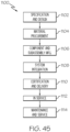
- examples of the system 100, the system 300, the method 1000 and the method 1200 may be related to, or used in the context of, an aircraft manufacturing and service method 1100, as shown in the flow diagram of Fig. 45 and an aircraft 700, as schematically illustrated in Fig. 43 .
- the composite structure 102 manufactured using the system 100 or in accordance with the method 1000 may be any one of a structure, an assembly, a subassembly, a component, a part, or any other portion of the aircraft 700, such as a portion of an airframe, interior, and one or more of the high-level systems.
- the composite structure 102 may be any one of an aircraft spar, a wing section, a fuselage barrel section, an interior panel, an exterior skin panel, and the like.
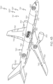
- Fig. 43 schematically illustrates an example of the aircraft 700.
- the aircraft 700 includes a plurality of high-level systems 800.
- the high-level systems 800 include one or more of a propulsion system 810, an electrical system 802, a hydraulic system 804, and an environmental control ("environmental") system 806.
- the aircraft 700 may include any number of other types of systems, such as a communications system, a flight control system, a guidance system, a weapons system, and the like.
- the aircraft 700 includes at least one composite structure 102.
- the composite structure 102 is at least partially fabricated utilizing the system 100 and/or the method 1000.
- the aircraft 700 may include a plurality of components, including an airframe 710, a fuselage 720, a fuselage barrel 730, an interior 808, a wing 740, and/or a stabilizer 750.
- the composite structure 102 includes at least one composite ply 106, such as a plurality of composite plies 106.
- the composite structure 102 may form a composite part or a portion of any suitable component of the aircraft 700.
- the aircraft 700 includes skin segments 790 that cover and/or form an outer surface of any suitable portion of the aircraft 700 and/or a plurality of stringers 770 that, together with a plurality of frames, may support an inner surface of the skin segments 790.
- Fig. 44 schematically illustrates an example of the wing 740.
- the wing 740 includes a plurality of wing stringers 742, which may extend along a length of the wing 740.
- the wing 740 may also include a plurality of spars 744, which also may be referred to herein as ribs.
- the wing stringers 742 and spars 744 together may form and/or define at least a portion of an inner support structure 746 for the wing 740, which may support an inner surface 748 of the skin segments 790 that cover the wing 740.
- the skin segments 790 may also be referred to herein as wing skin segments.
- the skin segments 790 e.g., wing skin or fuselage skin
- stringers 770 e.g., fuselage stringers
- frames e.g., multiple piece frames or one piece frames
- the skin segments 790 e.g., wing skin or fuselage skin
- stringers 770 e.g., fuselage stringers
- frames e.g., multiple piece frames or one piece frames
- the method 1100 includes specification and design of the aircraft 700 (block 1102) and material procurement (block 1104).
- component and subassembly manufacturing (block 1106) and system integration (block 1108) of the aircraft 700 take place. Thereafter, the aircraft 700 goes through certification and delivery (block 1110) to be placed in service (block 1112).
- Routine maintenance and service (block 1114) includes modification, reconfiguration, refurbishment, etc. of one or more systems of the aircraft 700.
- the composite structure 102 manufactured in accordance with the method 1000 may be produced during material procurement (block 1104), component and subassembly manufacturing (block 1106), and/or maintenance and service (block 1114).
- a system integrator may include, without limitation, any number of spacecraft manufacturers and major-system subcontractors; a third party may include, without limitation, any number of vendors, subcontractors, and suppliers; and an operator may be an airline, leasing company, military entity, service organization, and so on.
- Examples of the aircraft 700, the composite structure 102, the system 100, the system 300, the method 1000 and the method 1200 shown and described herein may be employed during any one or more of the stages of the manufacturing and service method 1100 shown in the flow diagram illustrated by Fig. 45 .
- implementations of the system 100, the system 300, the method 1000 and the method 1200 may form a portion of component and subassembly manufacturing (block 1106) and/or system integration (block 1108).
- composite structures 102 made using implementations of the disclosed system 100, system 300, method 1000 and method 1200 may correspond to component and subassembly manufacturing (block 1106) and may be utilized in a manner similar to components or subassemblies prepared while the aircraft 700 is in service (block 1112).
- implementations of the disclosed system 100, system 300, method 1000 and method 1200 may be utilized during system integration (block 1108) and certification and delivery (block 1110).
- implementations of the disclosed system 100, system 300, method 1000 and method 1200 may be utilized, for example and without limitation, while the aircraft 700 is in service (block 1112) and during maintenance and service (block 1114).
- a method of fabricating a portion of the aircraft 700 ( Fig. 43 ) using the system 100 and/or the system 300. Also disclosed is a portion of the aircraft 700 manufactured in accordance with the method 1000 or the method 1200.
- the examples and principles disclosed herein may be applied to other industries, such as the automotive industry, the space industry, the construction industry, and other design and manufacturing industries. Accordingly, in addition to aircraft, the examples and principles disclosed herein may apply to systems for disinfecting an interior of other types of vehicles (e.g., land vehicles, marine vehicles, space vehicles, etc.) and stand-alone structures.
- vehicles e.g., land vehicles, marine vehicles, space vehicles, etc.
- a system, apparatus, device, structure, article, element, component, or hardware "configured to” perform a specified function is indeed capable of performing the specified function without any alteration, rather than merely having potential to perform the specified function after further modification.
- the system, apparatus, device, structure, article, element, component, or hardware "configured to” perform a specified function is specifically selected, created, implemented, utilized, programmed, and/or designed for the purpose of performing the specified function.
- "configured to” denotes existing characteristics of a system, apparatus, structure, article, element, component, or hardware that enable the system, apparatus, structure, article, element, component, or hardware to perform the specified function without further modification.
- a system, apparatus, device, structure, article, element, component, or hardware described as being “configured to” perform a particular function may additionally or alternatively be described as being “adapted to” and/or as being “operative to” perform that function.
- first,” “second,” “third,” etc. are used herein merely as labels, and are not intended to impose ordinal, positional, or hierarchical requirements on the items to which these terms refer. Moreover, reference to, e.g., a “second” item does not require or preclude the existence of, e.g., a "first” or lower-numbered item, and/or, e.g., a "third” or higher-numbered item.
- the phrase "at least one of”, when used with a list of items, means different combinations of one or more of the listed items may be used and only one of each item in the list may be needed.
- “at least one of item A, item B, and item C” may include, without limitation, item A or item A and item B. This example also may include item A, item B, and item C, or item B and item C.
- "at least one of” may be, for example, without limitation, two of item A, one of item B, and ten of item C; four of item B and seven of item C; and other suitable combinations.
- Coupled refers to two or more elements that are joined, linked, fastened, attached, connected, put in communication, or otherwise associated (e.g., mechanically, electrically, fluidly, optically, electromagnetically) with one another.
- the elements may be associated directly or indirectly.
- element A may be directly associated with element B.
- element A may be indirectly associated with element B, for example, via another element C. It will be understood that not all associations among the various disclosed elements are necessarily represented. Accordingly, couplings other than those depicted in the figures may also exist.
- the term “approximately” refers to or represent a condition that is close to, but not exactly, the stated condition that still performs the desired function or achieves the desired result.
- the term “approximately” refers to a condition that is within an acceptable predetermined tolerance or accuracy, such as to a condition that is within 10% of the stated condition.
- the term “approximately” does not exclude a condition that is exactly the stated condition.
- the term “substantially” refers to a condition that is essentially the stated condition that performs the desired function or achieves the desired result.
- Fig. 36 the blocks may represent functional elements, features, or components thereof and lines connecting the various blocks do not necessarily imply any particular structure. Accordingly, modifications, additions and/or omissions may be made to the illustrated structure. Additionally, those skilled in the art will appreciate that not all elements, features, and/or components described and illustrated in Figs. 1-34 , 36-41 , 43 and 44 , referred to above, need be included in every example and not all elements, features, and/or components described herein are necessarily depicted in each illustrative example. Accordingly, some of the elements, features, and/or components described and illustrated in Figs.
- Figs. 35 , 42 and 45 referred to above, the blocks may represent operations, steps, and/or portions thereof and lines connecting the various blocks do not imply any particular order or dependency of the operations or portions thereof. It will be understood that not all dependencies among the various disclosed operations are necessarily represented. Figs. 35 , 42 and 45 and the accompanying disclosure describing the operations of the disclosed methods set forth herein should not be interpreted as necessarily determining a sequence in which the operations are to be performed. Rather, although one illustrative order is indicated, it is to be understood that the sequence of the operations may be modified when appropriate. Accordingly, modifications, additions and/or omissions may be made to the operations illustrated and certain operations may be performed in a different order or simultaneously. Additionally, those skilled in the art will appreciate that not all operations described need be performed.
- references throughout the present specification to features, advantages, or similar language used herein do not imply that all of the features and advantages that may be realized with the examples disclosed herein should be, or are in, any single example. Rather, language referring to the features and advantages is understood to mean that a specific feature, advantage, or characteristic described in connection with an example is included in at least one example. Thus, discussion of features, advantages, and similar language used throughout the present disclosure may, but do not necessarily, refer to the same example.
Landscapes
- Engineering & Computer Science (AREA)
- Mechanical Engineering (AREA)
- Robotics (AREA)
- Chemical & Material Sciences (AREA)
- Composite Materials (AREA)
- Moulding By Coating Moulds (AREA)
Claims (15)
- System (300) zum Ablegen einer Verbundlage (106), wobei das System (300) aufweist:einen Transfer-Endeffektor (302), der relativ zu einer Trägertransfereinrichtung (110) beweglich ist und konfiguriert ist, einen Lagenträger (104) zu fördern, der die Verbundlage (106) trägt, wobei der Lagenträger (104) eine Grundplatte (124) aufweist, die magnetisch ist, sowie eine auf der Grundplatte (124) angeordnete Folie (126), die eine Lageauflagefläche (108) für die Verbundlage (106) bildet, wobei der Transfer-Endeffektor (302) eine Magnetspannvorrichtung (310) aufweist, die konfiguriert ist, die Grundplatte (124) magnetisch zu erfassen, um den Lagenträger (104) durch den Transfer-Endeffektor (302) von der Trägertransfereinrichtung (110) zu entnehmen; undeinen Ablege-Endeffektor (304), der relativ zum Transfer-Endeffektor (302) und zu einem Formwerkzeug (120) beweglich ist, wobei die Magnetspannvorrichtung (310) des Weiteren konfiguriert ist, die Grundplatte (124) magnetisch zu lösen, um den Lagenträger (104) durch den Ablege-Endeffektor (304) vom Transfer-Endeffektor (302) zu entnehmen;wobei:der Transfer-Endeffektor (302) konfiguriert ist, den Lagenträger (104), der die Verbundlage (106) trägt, von der Trägertransfereinrichtung (110) zu entnehmen und den Lagenträger (104) zur Entnahme durch den Ablege-Endeffektor (304) zu positionieren; undder Ablege-Endeffektor (304) konfiguriert ist, den Lagenträger (104) vom Transfer-Endeffektor (302) zu entnehmen und die Verbundlage (106) auf das Formwerkzeug (120) aufzubringen.
- System (300) nach Anspruch 1, wobei der Ablege-Endeffektor (304) eine Vakuumspannvorrichtung (312) aufweist und die Vakuumspannvorrichtung (312) konfiguriert ist, selektiv ein Haltevakuum an die Grundplatte (124) anzulegen, um den Lagenträger (104) durch den Ablege-Endeffektor (304) von dem Transfer-Endeffektor (302) zu entnehmen.
- System (300) nach Anspruch 1, wobei:
der Transfer-Endeffektor (302) aufweist:einen Transferrahmen (314); undeine Magnetspannvorrichtung (310), die mit dem Transferrahmen (314) gekoppelt ist und eine Magnetspannvorrichtung-Kontaktfläche (318) aufweist; undwobei die Magnetspannvorrichtung (310) relativ zu dem Transferrahmen (314) beweglich ist, um die Magnetspannvorrichtung-Kontaktfläche (318) in Kontakt mit der Verbundlage (106) zu bringen, die von dem Lagenträger (104) getragen wird, um den Lagenträger (104) durch den Transfer-Endeffektor (302) von der Trägertransfereinrichtung (110) zu entnehmen. - System (300) nach Anspruch 3, wobei die Magnetspannvorrichtung (310) des Weiteren aufweist:ein Magnetspannvorrichtung-Trägerelement (328) aufweist, das mit dem Transferrahmen (314) gekoppelt und relativ dazu beweglich ist; undeine Vielzahl von Magneten (320), die mit dem Magnetspannvorrichtung-Trägerelement (328) gekoppelt sind.
- System (300) nach Anspruch 4, wobei die Magnetspannvorrichtung (310) des Weiteren ein elastisches Magnetspannvorrichtungselement (330) aufweist, das mit dem Magnetspannvorrichtung-Trägerelement (328) gekoppelt ist und sich gegenüberliegend zum Transferrahmen (314) befindet.
- System (300) nach Anspruch 3, des Weiteren aufweisend eine Transfer-Stützplattform (306), die mit dem Transferrahmen (314) des Transfer-Endeffektors (302) gekoppelt ist, wobei der Transfer-Endeffektor (302) um eine Rotationsachse (322) relativ zur Transfer-Stützplattform (306) drehbar ist, um den Lagenträger (104) für die Entnahme durch den Ablege-Endeffektor (304) aus dem Transfer-Endeffektor (302) zu positionieren.
- System (300) nach Anspruch 3, wobei:der Transfer-Endeffektor (302) des Weiteren aufweist:einen Transfer-Aktuator (348), der mit dem Transferrahmen (314) und der Magnetspannvorrichtung (310) gekoppelt ist; undeine Transferführung (350), die mit dem Transferrahmen (314) und der Magnetspannvorrichtung (310) gekoppelt ist;wobei der Transfer-Aktuator (348) konfiguriert ist, die Bewegung der Magnetspannvorrichtung (310) relativ zum Transferrahmen (314) entlang einer ersten Bewegungsachse (352) zu steuern;wobei die Transferführung (350) konfiguriert ist, die Bewegung der Magnetspannvorrichtung (310) entlang der ersten Bewegungsachse (352) zu führen; undwobei die Transferführung (350) des Weiteren konfiguriert ist, eine Bewegung der Magnetspannvorrichtung (310) relativ zum Transferrahmen (314) entlang einer Schwebeachse (354) zu ermöglichen, die senkrecht zur ersten Bewegungsachse (352) verläuft.
- System (300) nach Anspruch 3, wobei der Transfer-Endeffektor (302) einen ersten Abschnitt einer ersten Indexiervorrichtung (316) aufweist, die konfiguriert ist, mit einem zweiten Abschnitt der ersten Indexiervorrichtung (316) zu kooperieren, welcher sich an der Trägertransfereinrichtung (110) befindet, um die Magnetspannvorrichtung (310) relativ zur Trägertransfereinrichtung (110) zu positionieren.
- System (300) nach Anspruch 1, wobei:der Ablege-Endeffektor (304) aufweist:einen Ablegerahmen (342); undeine Vakuumspannvorrichtung (312), die mit dem Ablegerahmen (342) gekoppelt ist und eine Vakuumspannvorrichtung-Kontaktfläche (346) aufweist; undwobei die Vakuumspannvorrichtung (312) relativ zum Ablegerahmen (342) beweglich ist, um die Vakuumspannvorrichtung-Kontaktfläche (346) in Kontakt mit dem Lagenträger (104) zu bringen, der die Verbundlage (106) trägt, um den Lagenträger (104) durch den Ablege-Endeffektor (304) vom Transfer-Endeffektor (302) zu entnehmen und den Lagenträger (104) für das Aufbringen der Verbundlage (106) auf das Formwerkzeug (120) durch den Ablege-Endeffektor (304) zu positionieren.
- System (300) nach Anspruch 9, des Weiteren aufweisend eine Ablege-Stützplattform (308), die mit dem Ablegerahmen (342) des Ablege-Endeffektors (304) gekoppelt ist, wobei der Ablege-Endeffektor (304) relativ zur Ablege-Stützplattform (308) beweglich ist, um den Lagenträger (104) für das Aufbringen der Verbundlage (104) auf das Formwerkzeug (120) durch den Ablege-Endeffektor (304) zu positionieren.
- System (300) nach Anspruch 2, wobei:die Grundplatte (124) eine Vielzahl von Vakuumöffnungen (128) aufweist; unddie Vakuumspannvorrichtung (312) des Weiteren konfiguriert ist, das Haltevakuum durch die Vielzahl von Vakuumöffnungen (128) anzulegen, um die Folie (126) auf der Grundplatte (124) zu halten.
- System (300) nach Anspruch 5, wobei die Magnetspannvorrichtung (310) des Weiteren eine Magnetspannvorrichtung-Auskleidung (336) aufweist, die mit dem elastischen Magnetspannvorrichtungselement (330) gekoppelt ist.
- System (300) nach Anspruch 5 oder 12, wobei die Vielzahl von Magneten (320) relativ zum Magnetspannvorrichtung-Trägerelement (328) beweglich ist.
- Fertigungssystem (100) zur Herstellung einer Verbundstruktur (102), aufweisend:einen Lagenträger (104), der eine Lageauflagefläche (108) aufweist, die konfiguriert ist, mindestens eine Verbundlage (106) zu tragen;eine Trägertransfereinrichtung (110), die konfiguriert ist, den Lagenträger (104) zu fördern;ein Laminierungssystem (112), das konfiguriert ist, die mindestens eine Verbundlage (106) selektiv auf die Lageauflagefläche (108) des Lagenträgers (104) aufzubringen;ein System (300) nach einem der Ansprüche 1 bis 13, wobei das Transfersystem (300) konfiguriert ist, den Lagenträger (104) von der Trägertransfereinrichtung (110) zu entnehmen und die mindestens eine Verbundlage (106) auf mindestens einen Abschnitt einer Formoberfläche (118) eines Formwerkzeugs (120) aufzubringen, undein Formsystem (122), das konfiguriert ist, die mindestens eine Verbundlage (106) über mindestens einen Abschnitt der Formoberfläche (118) des Formwerkzeugs (120) zu formen.
- Verfahren (1000) zum Herstellen einer Verbundstruktur (102), aufweisend die Schritte:Fördern eines Lagenträgers (104) zu einem Laminierungssystem (112) unter Verwendung einer Trägertransfereinrichtung (110);selektives Aufbringen von mindestens einer Verbundlage (106) auf eine Lageauflagefläche (108) des Lagenträgers (104) unter Verwendung des Laminierungssystems (112);Fördern des Lagenträgers (104) vom Laminierungssystem (112) zu einem Transfersystem (300) unter Verwendung der Trägertransfereinrichtung (110);Entnehmen des Lagenträgers (104) von der Trägertransfereinrichtung (110) und Aufbringen der mindestens einen Verbundlage (106) auf mindestens einen Abschnitt einer Formoberfläche (118) eines Formwerkzeugs (120) unter Verwendung des Systems (300) nach einem der Ansprüche 1 bis 13; undFormen der mindestens einen Verbundlage (106) über mindestens einen Abschnitt der Formoberfläche (118) des Formwerkzeugs (120) unter Verwendung eines Formsystems (122).
Applications Claiming Priority (1)
| Application Number | Priority Date | Filing Date | Title |
|---|---|---|---|
| US202063199095P | 2020-12-07 | 2020-12-07 |
Publications (2)
| Publication Number | Publication Date |
|---|---|
| EP4008532A1 EP4008532A1 (de) | 2022-06-08 |
| EP4008532B1 true EP4008532B1 (de) | 2025-03-26 |
Family
ID=78676399
Family Applications (1)
| Application Number | Title | Priority Date | Filing Date |
|---|---|---|---|
| EP21208618.5A Active EP4008532B1 (de) | 2020-12-07 | 2021-11-16 | System und verfahren zur platzierung von verbundlagen |
Country Status (3)
| Country | Link |
|---|---|
| US (1) | US11654641B2 (de) |
| EP (1) | EP4008532B1 (de) |
| CN (1) | CN114590593A (de) |
Families Citing this family (4)
| Publication number | Priority date | Publication date | Assignee | Title |
|---|---|---|---|---|
| CN115625961B (zh) * | 2022-11-01 | 2025-08-15 | 程力新富襄阳汽车股份有限公司 | 一种车身板材生产线的抽真空平台 |
| US20250121553A1 (en) * | 2023-10-13 | 2025-04-17 | The Boeing Company | Pick and place end effector configured to form a kink |
| WO2026013558A1 (en) * | 2024-07-09 | 2026-01-15 | Voidless S.R.L. | System for handling a sheet for packaging between successive workstations of a line for the production of boxes |
| CN119772927B (zh) * | 2025-02-25 | 2026-01-30 | 中国电建集团福建工程有限公司 | 一种光伏组件装配装置及其安装方法 |
Family Cites Families (20)
| Publication number | Priority date | Publication date | Assignee | Title |
|---|---|---|---|---|
| US4208238A (en) | 1977-07-11 | 1980-06-17 | Grumman Aerospace Corporation | Gantry for use in the manufacture of laminar structures |
| GB8805922D0 (en) | 1988-03-12 | 1988-04-13 | Holroyd Associates Ltd | Improvements in & relating to handling means |
| US5209804A (en) | 1991-04-30 | 1993-05-11 | United Technologies Corporation | Integrated, automted composite material manufacturing system for pre-cure processing of preimpregnated composite materials |
| US6814916B2 (en) | 2002-08-30 | 2004-11-09 | The Boeing Company | Forming method for composites |
| US7118370B2 (en) | 2002-08-30 | 2006-10-10 | The Boeing Company | Composite spar drape forming machine |
| US7137182B2 (en) | 2002-11-22 | 2006-11-21 | The Boeing Company | Parallel configuration composite material fabricator |
| US8336596B2 (en) | 2002-11-22 | 2012-12-25 | The Boeing Company | Composite lamination using array of parallel material dispensing heads |
| KR101302250B1 (ko) * | 2008-09-30 | 2013-09-02 | 가와사키 쥬코교 가부시키가이샤 | 로봇용 모니터링 장치 |
| US8808490B2 (en) | 2011-08-04 | 2014-08-19 | The Boeing Company | Methods for laminating composites |
| US9663247B2 (en) | 2015-02-27 | 2017-05-30 | The Boeing Company | Systems, methods, and vacuum chucks for transferring flexible elongate bodies |
| US10086596B2 (en) | 2015-03-12 | 2018-10-02 | The Boeing Company | Apparatus and method for automated layup of composite structures |
| US10800111B2 (en) | 2015-06-16 | 2020-10-13 | The Boeing Company | Composite structure fabrication systems and methods |
| US10456960B2 (en) | 2015-07-24 | 2019-10-29 | The Boeing Company | Systems and methods for incrementally forming a composite part |
| US10688697B2 (en) | 2016-01-22 | 2020-06-23 | The Boeing Company | Apparatus and method of forming a composite structure |
| TW201805174A (zh) * | 2016-08-01 | 2018-02-16 | 陽程科技股份有限公司 | 曲面貼合裝置及貼合方法 |
| US10160169B1 (en) * | 2017-06-26 | 2018-12-25 | General Electric Company | Systems and methods of forming a composite layup structure |
| US10926490B2 (en) | 2018-04-09 | 2021-02-23 | The Boeing Company | Composite laminate forming apparatus and method therefor |
| US11565485B2 (en) | 2019-10-14 | 2023-01-31 | The Boeing Company | System, method, and apparatus for use in ply compaction in forming a composite structure |
| US11969957B2 (en) | 2019-10-14 | 2024-04-30 | The Boeing Company | System, method, and apparatus for use in forming a composite structure |
| US11865825B2 (en) | 2019-10-14 | 2024-01-09 | The Boeing Company | System, method, and apparatus for use in ply compaction in forming a composite structure |
-
2021
- 2021-11-01 US US17/516,050 patent/US11654641B2/en active Active
- 2021-11-16 EP EP21208618.5A patent/EP4008532B1/de active Active
- 2021-12-07 CN CN202111482946.2A patent/CN114590593A/zh active Pending
Also Published As
| Publication number | Publication date |
|---|---|
| CN114590593A (zh) | 2022-06-07 |
| US20220176650A1 (en) | 2022-06-09 |
| EP4008532A1 (de) | 2022-06-08 |
| US11654641B2 (en) | 2023-05-23 |
Similar Documents
| Publication | Publication Date | Title |
|---|---|---|
| EP4008532B1 (de) | System und verfahren zur platzierung von verbundlagen | |
| ES2628443T3 (es) | Método de fabricación compuesto que usa un conjunto de módulos compuestos | |
| EP3112137B1 (de) | Verfahren und vorrichtung zur formung profilierter versteifungen | |
| US10155347B2 (en) | Composite stiffener positioning and vacuum bag installation device | |
| EP2014448A2 (de) | Verfahren und Vorrichtung zur Konturierung von vorimpregnierten Verbundteile | |
| US11155069B2 (en) | Method and system of forming a composite laminate | |
| EP4008533B1 (de) | System und verfahren zur herstellung einer verbundstruktur | |
| EP3480002B1 (de) | Systeme und verfahren zur in-situ-herstellung von minimal bearbeiteten holmen | |
| US9586344B2 (en) | Method and system of forming a releasable support and method of pre-cure removal of a composite laminate | |
| EP3023234A1 (de) | Herstellung von versteiften Verbundplatten | |
| US9545758B2 (en) | Two piece mandrel manufacturing system | |
| US11806947B2 (en) | Forming system and method for forming a contoured composite structure | |
| EP4194172B1 (de) | Biegsame strukturen und zugehörige verfahren und systeme zur replikation einer kontur einer oberfläche | |
| US11826970B2 (en) | Forming apparatus, method, and system | |
| EP4008531B1 (de) | Herstellungsvorrichtung, verfahren und system | |
| EP4008535B1 (de) | Vorrichtung, verfahren und system zur formen | |
| EP4197719B1 (de) | Greifvorrichtung und zugehörige systeme und verfahren zum greifen von flexiblen materialien | |
| US12103249B2 (en) | Composite forming apparatus, methods, and systems |
Legal Events
| Date | Code | Title | Description |
|---|---|---|---|
| PUAI | Public reference made under article 153(3) epc to a published international application that has entered the european phase |
Free format text: ORIGINAL CODE: 0009012 |
|
| STAA | Information on the status of an ep patent application or granted ep patent |
Free format text: STATUS: THE APPLICATION HAS BEEN PUBLISHED |
|
| AK | Designated contracting states |
Kind code of ref document: A1 Designated state(s): AL AT BE BG CH CY CZ DE DK EE ES FI FR GB GR HR HU IE IS IT LI LT LU LV MC MK MT NL NO PL PT RO RS SE SI SK SM TR |
|
| STAA | Information on the status of an ep patent application or granted ep patent |
Free format text: STATUS: REQUEST FOR EXAMINATION WAS MADE |
|
| 17P | Request for examination filed |
Effective date: 20221122 |
|
| RBV | Designated contracting states (corrected) |
Designated state(s): AL AT BE BG CH CY CZ DE DK EE ES FI FR GB GR HR HU IE IS IT LI LT LU LV MC MK MT NL NO PL PT RO RS SE SI SK SM TR |
|
| RAP3 | Party data changed (applicant data changed or rights of an application transferred) |
Owner name: THE BOEING COMPANY |
|
| GRAP | Despatch of communication of intention to grant a patent |
Free format text: ORIGINAL CODE: EPIDOSNIGR1 |
|
| STAA | Information on the status of an ep patent application or granted ep patent |
Free format text: STATUS: GRANT OF PATENT IS INTENDED |
|
| RIC1 | Information provided on ipc code assigned before grant |
Ipc: B65H 5/10 20060101ALN20241111BHEP Ipc: B65H 5/04 20060101ALN20241111BHEP Ipc: B29L 31/30 20060101ALN20241111BHEP Ipc: B65H 3/08 20060101ALI20241111BHEP Ipc: B65H 3/16 20060101ALI20241111BHEP Ipc: B65H 3/12 20060101ALI20241111BHEP Ipc: B29C 70/54 20060101ALI20241111BHEP Ipc: B25J 5/02 20060101ALI20241111BHEP Ipc: B29C 31/08 20060101ALI20241111BHEP Ipc: B29C 70/38 20060101AFI20241111BHEP |
|
| INTG | Intention to grant announced |
Effective date: 20241129 |
|
| RIC1 | Information provided on ipc code assigned before grant |
Ipc: B65H 5/10 20060101ALN20241122BHEP Ipc: B65H 5/04 20060101ALN20241122BHEP Ipc: B29L 31/30 20060101ALN20241122BHEP Ipc: B65H 3/08 20060101ALI20241122BHEP Ipc: B65H 3/16 20060101ALI20241122BHEP Ipc: B65H 3/12 20060101ALI20241122BHEP Ipc: B29C 70/54 20060101ALI20241122BHEP Ipc: B25J 5/02 20060101ALI20241122BHEP Ipc: B29C 31/08 20060101ALI20241122BHEP Ipc: B29C 70/38 20060101AFI20241122BHEP |
|
| GRAS | Grant fee paid |
Free format text: ORIGINAL CODE: EPIDOSNIGR3 |
|
| GRAA | (expected) grant |
Free format text: ORIGINAL CODE: 0009210 |
|
| STAA | Information on the status of an ep patent application or granted ep patent |
Free format text: STATUS: THE PATENT HAS BEEN GRANTED |
|
| AK | Designated contracting states |
Kind code of ref document: B1 Designated state(s): AL AT BE BG CH CY CZ DE DK EE ES FI FR GB GR HR HU IE IS IT LI LT LU LV MC MK MT NL NO PL PT RO RS SE SI SK SM TR |
|
| REG | Reference to a national code |
Ref country code: GB Ref legal event code: FG4D |
|
| REG | Reference to a national code |
Ref country code: CH Ref legal event code: EP |
|
| P01 | Opt-out of the competence of the unified patent court (upc) registered |
Free format text: CASE NUMBER: APP_10844/2025 Effective date: 20250305 |
|
| REG | Reference to a national code |
Ref country code: DE Ref legal event code: R096 Ref document number: 602021028071 Country of ref document: DE |
|
| REG | Reference to a national code |
Ref country code: IE Ref legal event code: FG4D |
|
| PG25 | Lapsed in a contracting state [announced via postgrant information from national office to epo] |
Ref country code: RS Free format text: LAPSE BECAUSE OF FAILURE TO SUBMIT A TRANSLATION OF THE DESCRIPTION OR TO PAY THE FEE WITHIN THE PRESCRIBED TIME-LIMIT Effective date: 20250626 |
|
| PG25 | Lapsed in a contracting state [announced via postgrant information from national office to epo] |
Ref country code: FI Free format text: LAPSE BECAUSE OF FAILURE TO SUBMIT A TRANSLATION OF THE DESCRIPTION OR TO PAY THE FEE WITHIN THE PRESCRIBED TIME-LIMIT Effective date: 20250326 |
|
| REG | Reference to a national code |
Ref country code: LT Ref legal event code: MG9D |
|
| PG25 | Lapsed in a contracting state [announced via postgrant information from national office to epo] |
Ref country code: NO Free format text: LAPSE BECAUSE OF FAILURE TO SUBMIT A TRANSLATION OF THE DESCRIPTION OR TO PAY THE FEE WITHIN THE PRESCRIBED TIME-LIMIT Effective date: 20250626 |
|
| PG25 | Lapsed in a contracting state [announced via postgrant information from national office to epo] |
Ref country code: HR Free format text: LAPSE BECAUSE OF FAILURE TO SUBMIT A TRANSLATION OF THE DESCRIPTION OR TO PAY THE FEE WITHIN THE PRESCRIBED TIME-LIMIT Effective date: 20250326 |
|
| PG25 | Lapsed in a contracting state [announced via postgrant information from national office to epo] |
Ref country code: LV Free format text: LAPSE BECAUSE OF FAILURE TO SUBMIT A TRANSLATION OF THE DESCRIPTION OR TO PAY THE FEE WITHIN THE PRESCRIBED TIME-LIMIT Effective date: 20250326 |
|
| PG25 | Lapsed in a contracting state [announced via postgrant information from national office to epo] |
Ref country code: GR Free format text: LAPSE BECAUSE OF FAILURE TO SUBMIT A TRANSLATION OF THE DESCRIPTION OR TO PAY THE FEE WITHIN THE PRESCRIBED TIME-LIMIT Effective date: 20250627 Ref country code: BG Free format text: LAPSE BECAUSE OF FAILURE TO SUBMIT A TRANSLATION OF THE DESCRIPTION OR TO PAY THE FEE WITHIN THE PRESCRIBED TIME-LIMIT Effective date: 20250326 |
|
| REG | Reference to a national code |
Ref country code: NL Ref legal event code: MP Effective date: 20250326 |
|
| PG25 | Lapsed in a contracting state [announced via postgrant information from national office to epo] |
Ref country code: NL Free format text: LAPSE BECAUSE OF FAILURE TO SUBMIT A TRANSLATION OF THE DESCRIPTION OR TO PAY THE FEE WITHIN THE PRESCRIBED TIME-LIMIT Effective date: 20250326 |
|
| PG25 | Lapsed in a contracting state [announced via postgrant information from national office to epo] |
Ref country code: SE Free format text: LAPSE BECAUSE OF FAILURE TO SUBMIT A TRANSLATION OF THE DESCRIPTION OR TO PAY THE FEE WITHIN THE PRESCRIBED TIME-LIMIT Effective date: 20250326 |
|
| REG | Reference to a national code |
Ref country code: AT Ref legal event code: MK05 Ref document number: 1778655 Country of ref document: AT Kind code of ref document: T Effective date: 20250326 |
|
| PG25 | Lapsed in a contracting state [announced via postgrant information from national office to epo] |
Ref country code: SM Free format text: LAPSE BECAUSE OF FAILURE TO SUBMIT A TRANSLATION OF THE DESCRIPTION OR TO PAY THE FEE WITHIN THE PRESCRIBED TIME-LIMIT Effective date: 20250326 |
|
| PG25 | Lapsed in a contracting state [announced via postgrant information from national office to epo] |
Ref country code: ES Free format text: LAPSE BECAUSE OF FAILURE TO SUBMIT A TRANSLATION OF THE DESCRIPTION OR TO PAY THE FEE WITHIN THE PRESCRIBED TIME-LIMIT Effective date: 20250326 Ref country code: PT Free format text: LAPSE BECAUSE OF FAILURE TO SUBMIT A TRANSLATION OF THE DESCRIPTION OR TO PAY THE FEE WITHIN THE PRESCRIBED TIME-LIMIT Effective date: 20250728 |
|
| PG25 | Lapsed in a contracting state [announced via postgrant information from national office to epo] |
Ref country code: IT Free format text: LAPSE BECAUSE OF FAILURE TO SUBMIT A TRANSLATION OF THE DESCRIPTION OR TO PAY THE FEE WITHIN THE PRESCRIBED TIME-LIMIT Effective date: 20250326 Ref country code: PL Free format text: LAPSE BECAUSE OF FAILURE TO SUBMIT A TRANSLATION OF THE DESCRIPTION OR TO PAY THE FEE WITHIN THE PRESCRIBED TIME-LIMIT Effective date: 20250326 |
|
| PG25 | Lapsed in a contracting state [announced via postgrant information from national office to epo] |
Ref country code: AT Free format text: LAPSE BECAUSE OF FAILURE TO SUBMIT A TRANSLATION OF THE DESCRIPTION OR TO PAY THE FEE WITHIN THE PRESCRIBED TIME-LIMIT Effective date: 20250326 |
|
| PG25 | Lapsed in a contracting state [announced via postgrant information from national office to epo] |
Ref country code: EE Free format text: LAPSE BECAUSE OF FAILURE TO SUBMIT A TRANSLATION OF THE DESCRIPTION OR TO PAY THE FEE WITHIN THE PRESCRIBED TIME-LIMIT Effective date: 20250326 |
|
| PG25 | Lapsed in a contracting state [announced via postgrant information from national office to epo] |
Ref country code: RO Free format text: LAPSE BECAUSE OF FAILURE TO SUBMIT A TRANSLATION OF THE DESCRIPTION OR TO PAY THE FEE WITHIN THE PRESCRIBED TIME-LIMIT Effective date: 20250326 |
|
| PG25 | Lapsed in a contracting state [announced via postgrant information from national office to epo] |
Ref country code: SK Free format text: LAPSE BECAUSE OF FAILURE TO SUBMIT A TRANSLATION OF THE DESCRIPTION OR TO PAY THE FEE WITHIN THE PRESCRIBED TIME-LIMIT Effective date: 20250326 |
|
| PG25 | Lapsed in a contracting state [announced via postgrant information from national office to epo] |
Ref country code: IS Free format text: LAPSE BECAUSE OF FAILURE TO SUBMIT A TRANSLATION OF THE DESCRIPTION OR TO PAY THE FEE WITHIN THE PRESCRIBED TIME-LIMIT Effective date: 20250726 |
|
| REG | Reference to a national code |
Ref country code: DE Ref legal event code: R097 Ref document number: 602021028071 Country of ref document: DE |
|
| PGFP | Annual fee paid to national office [announced via postgrant information from national office to epo] |
Ref country code: DE Payment date: 20251128 Year of fee payment: 5 |
|
| PGFP | Annual fee paid to national office [announced via postgrant information from national office to epo] |
Ref country code: GB Payment date: 20251127 Year of fee payment: 5 |
|
| PG25 | Lapsed in a contracting state [announced via postgrant information from national office to epo] |
Ref country code: DK Free format text: LAPSE BECAUSE OF FAILURE TO SUBMIT A TRANSLATION OF THE DESCRIPTION OR TO PAY THE FEE WITHIN THE PRESCRIBED TIME-LIMIT Effective date: 20250326 |
|
| PGFP | Annual fee paid to national office [announced via postgrant information from national office to epo] |
Ref country code: FR Payment date: 20251125 Year of fee payment: 5 |
|
| PG25 | Lapsed in a contracting state [announced via postgrant information from national office to epo] |
Ref country code: CZ Free format text: LAPSE BECAUSE OF FAILURE TO SUBMIT A TRANSLATION OF THE DESCRIPTION OR TO PAY THE FEE WITHIN THE PRESCRIBED TIME-LIMIT Effective date: 20250326 |
|
| PLBE | No opposition filed within time limit |
Free format text: ORIGINAL CODE: 0009261 |
|
| STAA | Information on the status of an ep patent application or granted ep patent |
Free format text: STATUS: NO OPPOSITION FILED WITHIN TIME LIMIT |
|
| REG | Reference to a national code |
Ref country code: CH Ref legal event code: L10 Free format text: ST27 STATUS EVENT CODE: U-0-0-L10-L00 (AS PROVIDED BY THE NATIONAL OFFICE) Effective date: 20260211 |
|
| 26N | No opposition filed |
Effective date: 20260105 |