EP4008535B1 - Vorrichtung, verfahren und system zur formen - Google Patents
Vorrichtung, verfahren und system zur formen Download PDFInfo
- Publication number
- EP4008535B1 EP4008535B1 EP21208131.9A EP21208131A EP4008535B1 EP 4008535 B1 EP4008535 B1 EP 4008535B1 EP 21208131 A EP21208131 A EP 21208131A EP 4008535 B1 EP4008535 B1 EP 4008535B1
- Authority
- EP
- European Patent Office
- Prior art keywords
- forming
- ply
- swing arm
- forming tool
- stomp
- Prior art date
- Legal status (The legal status is an assumption and is not a legal conclusion. Google has not performed a legal analysis and makes no representation as to the accuracy of the status listed.)
- Active
Links
- 238000000034 method Methods 0.000 title claims description 47
- 239000002131 composite material Substances 0.000 claims description 146
- 238000004519 manufacturing process Methods 0.000 claims description 81
- 239000012636 effector Substances 0.000 claims description 57
- 238000012546 transfer Methods 0.000 claims description 34
- 238000005056 compaction Methods 0.000 claims description 24
- 230000001681 protective effect Effects 0.000 claims description 12
- 238000003475 lamination Methods 0.000 claims description 9
- 239000000463 material Substances 0.000 description 13
- 230000015572 biosynthetic process Effects 0.000 description 9
- 230000001419 dependent effect Effects 0.000 description 9
- 238000013461 design Methods 0.000 description 9
- 238000004891 communication Methods 0.000 description 8
- 230000008569 process Effects 0.000 description 7
- 238000010438 heat treatment Methods 0.000 description 5
- 230000000977 initiatory effect Effects 0.000 description 5
- 238000010586 diagram Methods 0.000 description 4
- 239000000835 fiber Substances 0.000 description 4
- 230000014759 maintenance of location Effects 0.000 description 4
- 230000009467 reduction Effects 0.000 description 4
- 230000010354 integration Effects 0.000 description 3
- 238000012423 maintenance Methods 0.000 description 3
- 238000009734 composite fabrication Methods 0.000 description 2
- 238000004590 computer program Methods 0.000 description 2
- 238000005520 cutting process Methods 0.000 description 2
- 238000010030 laminating Methods 0.000 description 2
- 238000002360 preparation method Methods 0.000 description 2
- 230000033228 biological regulation Effects 0.000 description 1
- 230000007613 environmental effect Effects 0.000 description 1
- 239000004744 fabric Substances 0.000 description 1
- 230000008014 freezing Effects 0.000 description 1
- 238000007710 freezing Methods 0.000 description 1
- 230000006870 function Effects 0.000 description 1
- 229910052736 halogen Inorganic materials 0.000 description 1
- 150000002367 halogens Chemical class 0.000 description 1
- 239000011159 matrix material Substances 0.000 description 1
- 238000012986 modification Methods 0.000 description 1
- 230000004048 modification Effects 0.000 description 1
- 230000008520 organization Effects 0.000 description 1
- 239000002861 polymer material Substances 0.000 description 1
- 239000004810 polytetrafluoroethylene Substances 0.000 description 1
- 229920001343 polytetrafluoroethylene Polymers 0.000 description 1
- 230000002265 prevention Effects 0.000 description 1
- 238000012545 processing Methods 0.000 description 1
- 238000009419 refurbishment Methods 0.000 description 1
- 238000012827 research and development Methods 0.000 description 1
- 239000011347 resin Substances 0.000 description 1
- 229920005989 resin Polymers 0.000 description 1
- 238000003860 storage Methods 0.000 description 1
- 230000000153 supplemental effect Effects 0.000 description 1
Images


Classifications
-
- B—PERFORMING OPERATIONS; TRANSPORTING
- B29—WORKING OF PLASTICS; WORKING OF SUBSTANCES IN A PLASTIC STATE IN GENERAL
- B29C—SHAPING OR JOINING OF PLASTICS; SHAPING OF MATERIAL IN A PLASTIC STATE, NOT OTHERWISE PROVIDED FOR; AFTER-TREATMENT OF THE SHAPED PRODUCTS, e.g. REPAIRING
- B29C70/00—Shaping composites, i.e. plastics material comprising reinforcements, fillers or preformed parts, e.g. inserts
- B29C70/04—Shaping composites, i.e. plastics material comprising reinforcements, fillers or preformed parts, e.g. inserts comprising reinforcements only, e.g. self-reinforcing plastics
- B29C70/28—Shaping operations therefor
- B29C70/40—Shaping or impregnating by compression not applied
- B29C70/42—Shaping or impregnating by compression not applied for producing articles of definite length, i.e. discrete articles
-
- B—PERFORMING OPERATIONS; TRANSPORTING
- B29—WORKING OF PLASTICS; WORKING OF SUBSTANCES IN A PLASTIC STATE IN GENERAL
- B29C—SHAPING OR JOINING OF PLASTICS; SHAPING OF MATERIAL IN A PLASTIC STATE, NOT OTHERWISE PROVIDED FOR; AFTER-TREATMENT OF THE SHAPED PRODUCTS, e.g. REPAIRING
- B29C70/00—Shaping composites, i.e. plastics material comprising reinforcements, fillers or preformed parts, e.g. inserts
- B29C70/04—Shaping composites, i.e. plastics material comprising reinforcements, fillers or preformed parts, e.g. inserts comprising reinforcements only, e.g. self-reinforcing plastics
- B29C70/28—Shaping operations therefor
- B29C70/54—Component parts, details or accessories; Auxiliary operations, e.g. feeding or storage of prepregs or SMC after impregnation or during ageing
- B29C70/541—Positioning reinforcements in a mould, e.g. using clamping means for the reinforcement
-
- B—PERFORMING OPERATIONS; TRANSPORTING
- B29—WORKING OF PLASTICS; WORKING OF SUBSTANCES IN A PLASTIC STATE IN GENERAL
- B29C—SHAPING OR JOINING OF PLASTICS; SHAPING OF MATERIAL IN A PLASTIC STATE, NOT OTHERWISE PROVIDED FOR; AFTER-TREATMENT OF THE SHAPED PRODUCTS, e.g. REPAIRING
- B29C70/00—Shaping composites, i.e. plastics material comprising reinforcements, fillers or preformed parts, e.g. inserts
- B29C70/04—Shaping composites, i.e. plastics material comprising reinforcements, fillers or preformed parts, e.g. inserts comprising reinforcements only, e.g. self-reinforcing plastics
- B29C70/28—Shaping operations therefor
- B29C70/30—Shaping by lay-up, i.e. applying fibres, tape or broadsheet on a mould, former or core; Shaping by spray-up, i.e. spraying of fibres on a mould, former or core
- B29C70/34—Shaping by lay-up, i.e. applying fibres, tape or broadsheet on a mould, former or core; Shaping by spray-up, i.e. spraying of fibres on a mould, former or core and shaping or impregnating by compression, i.e. combined with compressing after the lay-up operation
- B29C70/345—Shaping by lay-up, i.e. applying fibres, tape or broadsheet on a mould, former or core; Shaping by spray-up, i.e. spraying of fibres on a mould, former or core and shaping or impregnating by compression, i.e. combined with compressing after the lay-up operation using matched moulds
-
- B—PERFORMING OPERATIONS; TRANSPORTING
- B29—WORKING OF PLASTICS; WORKING OF SUBSTANCES IN A PLASTIC STATE IN GENERAL
- B29C—SHAPING OR JOINING OF PLASTICS; SHAPING OF MATERIAL IN A PLASTIC STATE, NOT OTHERWISE PROVIDED FOR; AFTER-TREATMENT OF THE SHAPED PRODUCTS, e.g. REPAIRING
- B29C70/00—Shaping composites, i.e. plastics material comprising reinforcements, fillers or preformed parts, e.g. inserts
- B29C70/04—Shaping composites, i.e. plastics material comprising reinforcements, fillers or preformed parts, e.g. inserts comprising reinforcements only, e.g. self-reinforcing plastics
- B29C70/28—Shaping operations therefor
- B29C70/30—Shaping by lay-up, i.e. applying fibres, tape or broadsheet on a mould, former or core; Shaping by spray-up, i.e. spraying of fibres on a mould, former or core
- B29C70/38—Automated lay-up, e.g. using robots, laying filaments according to predetermined patterns
-
- B—PERFORMING OPERATIONS; TRANSPORTING
- B29—WORKING OF PLASTICS; WORKING OF SUBSTANCES IN A PLASTIC STATE IN GENERAL
- B29D—PRODUCING PARTICULAR ARTICLES FROM PLASTICS OR FROM SUBSTANCES IN A PLASTIC STATE
- B29D99/00—Subject matter not provided for in other groups of this subclass
- B29D99/0003—Producing profiled members, e.g. beams
-
- B—PERFORMING OPERATIONS; TRANSPORTING
- B29—WORKING OF PLASTICS; WORKING OF SUBSTANCES IN A PLASTIC STATE IN GENERAL
- B29C—SHAPING OR JOINING OF PLASTICS; SHAPING OF MATERIAL IN A PLASTIC STATE, NOT OTHERWISE PROVIDED FOR; AFTER-TREATMENT OF THE SHAPED PRODUCTS, e.g. REPAIRING
- B29C43/00—Compression moulding, i.e. applying external pressure to flow the moulding material; Apparatus therefor
- B29C43/32—Component parts, details or accessories; Auxiliary operations
- B29C43/36—Moulds for making articles of definite length, i.e. discrete articles
- B29C43/3642—Bags, bleeder sheets or cauls for isostatic pressing
- B29C2043/3649—Inflatable bladders using gas or fluid and related details
-
- B—PERFORMING OPERATIONS; TRANSPORTING
- B29—WORKING OF PLASTICS; WORKING OF SUBSTANCES IN A PLASTIC STATE IN GENERAL
- B29L—INDEXING SCHEME ASSOCIATED WITH SUBCLASS B29C, RELATING TO PARTICULAR ARTICLES
- B29L2031/00—Other particular articles
- B29L2031/30—Vehicles, e.g. ships or aircraft, or body parts thereof
- B29L2031/3076—Aircrafts
Definitions
- the present application relates to manufacturing of composite parts, and is particularly directed to an apparatus, method, and system of ply by ply forming of composite parts.
- Formed composite structures are commonly used in applications where light weight and high strength are desired, such as in aircraft and vehicles. Often, these applications utilize contoured parts that must be formed and then cured.
- Conventional formation of composite structures, particularly relatively large composite structures or composite structures having a complex contour requires extensive manual labor prior to curing.
- composite fiber plies e.g., pre-impregnated fiber plies or dry fabric
- the part is then cured, often by heating and pressure.
- the resulting part matches the shape of the forming tool.
- manual layup of the fiber plies is time consuming and laborious.
- a drape forming process includes heating a laminate stack of pre-impregnated fiber plies ("composite charge”) and forcing it around a mandrel with the use of a vacuum bag or rubber bladder.
- composite charge pre-impregnated fiber plies
- a compactor may be used to compress the composite charge against a tool surface during fabrication.
- this method often requires supplemental manual formation after compaction when the tool surface and resulting structure is contoured. Accordingly, while such methods may be effective at forming relatively small and thin composite structures or composite structures with relatively simple shapes, they may be inefficient when applied to forming large composite structures or composite structures with more complex shapes.
- Document EP 3067187 A1 discloses an apparatus for forming a material layer onto a form tool including at least one nosepiece configured to laterally sweep a ply carrier onto a form tool contour.
- the apparatus includes a pair of tension arms configured to support opposing lateral sides of a ply carrier having a material layer mounted to a lower surface thereof.
- the apparatus includes one or more actuators configured to position the tension arms during forming of the ply carrier to the form tool contour.
- the one or more actuators are configured to sense and control lateral tension in the ply carrier during forming of the ply carrier to the form tool contour.
- Document DE 102011050099 A1 discloses a draping tool having telescopic outer grippers for retaining a composite material mat i.e. composite material mat stack. Heating elements i.e. halogen radiators, perform partial heat treatment of the mat at the tool.
- the grippers are arranged at an elongated base body of the tool and pneumatically actuatable. The heating elements are arranged next to a base element. Form strips are movable relative to the base body, arranged at sides of the base body and movably activated by a position actuator.
- the grippers are designed as suction grippers, needle grippers and/or freezing grippers.
- Also disclosed is a method for forming a composite part comprising the steps described at claim 9.
- Claim 12 describes an advantageous form of embodiment of the system.
- the present application is directed to an apparatus, method, and system of ply by ply forming of composite parts. It is to be understood that the disclosure below provides a number of embodiments or examples for implementing different features of various embodiments. Specific examples of components and arrangements are described to simplify the present disclosure. Illustrative, non-exhaustive examples, which may be, but are not necessarily, claimed, of the subject matter according the present disclosure are provided below. Reference herein to "example” means that one or more feature, structure, element, component, characteristic, and/or operational step described in connection with the example is included in at least one aspect, embodiment, and/or implementation of the subject matter according to the present disclosure.
- the phrases "an example,” “another example,” “one or more examples,” and similar language throughout the present disclosure may, but do not necessarily, refer to the same example.
- the subject matter characterizing any one example may, but does not necessarily, include the subject matter characterizing any other example.
- the subject matter characterizing any one example may be, but is not necessarily, combined with the subject matter characterizing any other example.
- Examples of the forming apparatus 100 ( FIG. 1 ), method 200 ( FIG. 10 ), and system 300 ( FIG. 11 ) enable automated forming of a composite part 375 and, more particularly, formation of at least one ply 320 of composite material 325 over a forming tool 310 for manufacture of the composite part 375.
- Automation of the fabrication process provides a reduction in processing time, a reduction in labor and costs and a reduction of process variations (e.g., human error) that may lead to undesired inconsistencies in the finished composite structure as compared to conventional composite fabrication.
- the forming apparatus 100, method 200, and system 300 also enable ply-by-ply formation of the composite material 325 to fabricate the composite part 375.
- Ply-by-ply formation facilitates fabrication of large composite structures, thick composite structures and/or composite structures with complex shapes.
- Ply-by-ply formation also provides a reduction in buckling or wrinkling of plies within the composite structure as compared to conventional composite fabrication.
- a composite ply includes a single ply (e.g., one layer of thickness) of composite material 325.
- the composite material 325 may take the form of any one of various suitable types of composite material 325.
- the ply 320 of composite material 325 is formed by laminating multiple courses of unidirectional composite tape, which is pre-impregnated with a resin matrix.
- the phrase "the ply" refers to at least one ply 320 of composite material 325, unless explicitly stated otherwise.
- the ply 320 may also be referred to as a composite patch or a composite charge.
- composite manufacturing system 600 includes a plurality of sub-systems, including a forming system 300 ( FIG. 11 ), that facilitate and correspond to different fabrication operations associated with the manufacture of the composite part 375.
- the sub-systems of the composite manufacturing system 600 are interlinked and cooperate to automate at least a portion of the fabrication process.
- the sub-systems of the disclosed system 600 may be referred to as "systems" themselves or stations in which one or more fabrication operations occur.
- a system 300 for forming is shown and described in detail below.
- the examples of the forming apparatus 100, method 200, and system 300 described herein utilize a plurality of semi-automated or automated sub-systems to perform ply-by-ply formation and compaction of individual one or more ply 320 of composite material 325 on the forming tool 310.
- Ply-by-ply formation refers to the laydown of one or more ply 320 of composite material 325 on the forming tool 310 in a predetermined sequence, and the one or more ply 320 of composite material 325 is compacted onto the forming tool 310 individually after each ply 320 of composite material 325 is laid down, or after more than one ply 320 of composite material 325 had been laid down.
- a forming apparatus 100, a method 200, and a system 300 directed to ply by ply forming of a composite part 375 to apply pressure and manipulate plies on a forming tool 310.
- the forming apparatus 100, method 200, and system 300 utilize a forming tool 310 to define the shape of the composite part 375.
- the forming tool 310 may be any desired shape including a hat stringer forming tool 312, a spar forming tool 314, and a stringer forming tool 316.
- the forming tool 310 may accommodate any forming tool 310 shape variations including an "L" shape, a "Y" shape, and any combination thereof.
- the forming apparatus 100 is configured to apply pressure or compaction force 350 evenly across at least one ply 320 of composite material 325 over a forming surface 308 of a forming tool 310.
- the forming apparatus 100 is further configured to deform 220 the at least one ply 320 of composite material 325 over the forming surface 308 of the forming tool 310 while eliminating any bubbles.
- the forming apparatus 100 is configured to move along the forming tool 310 at varying speeds, pressures, and angles to accommodate various geometries.
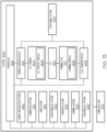
- FIG. 1 and FIG. 13 illustrate an example composite manufacturing composite manufacturing system 600.
- the composite manufacturing composite manufacturing system 600 includes a lamination system 612 (e.g., laminating sub-system or station), a transfer system 616 (e.g., transfer sub-system or station) and a forming system 622 (e.g., forming sub-system or station).
- the composite manufacturing composite manufacturing system 600 also includes a trim system 614 (e.g., trim sub-system or station) and a scrap removal system 642 (e.g., a scrap removal sub-system of station).
- the composite manufacturing composite manufacturing system 600 further includes a film removal system 660 (e.g., film removal sub-system or station).
- the composite manufacturing composite manufacturing system 600 additionally includes a carrier preparation system 662 (e.g., carrier preparation sub-system or station). In one or more examples, the composite manufacturing composite manufacturing system 600 also includes a positioning system 644 (e.g., positioning sub-system).
- a carrier preparation system 662 e.g., carrier preparation sub-system or station
- a positioning system 644 e.g., positioning sub-system
- the composite manufacturing system 600 includes a tool transfer device 646.
- the tool transfer device 646 is configured to convey the forming tool 310.
- the tool transfer device 646 includes, or takes the form of, a mobile platform that supports the forming tool 310 and moves the forming tool 310 between the sub-systems of the composite manufacturing system 600 that implement composite structure fabrication operations of the composite manufacturing process.
- the composite manufacturing composite manufacturing system 600 for fabricating a composite part 375 includes a ply carrier 604 comprising a ply support surface 608 configured to support at least one ply 320 of composite material 325.
- the composite manufacturing composite manufacturing system 600 further includes a carrier transfer device 610 configured to convey the ply carrier 604, a lamination system 612 configured to selectively apply the at least one ply 320 of composite material 325 to the ply support surface 608 of the ply carrier 604, a transfer system 616 configured to remove the ply carrier 604 from the carrier transfer device 610 and to apply the at least one ply 320 of composite material 325 to at least a portion of a forming surface 308 of a forming tool 310, and a forming system 622 configured to form the at least one ply 320 of composite material 325 over the at least a portion of the forming surface 308 of the forming tool 310.
- the forming system 622 comprises a forming apparatus 100.
- the forming apparatus 100 is located in the forming system 622.
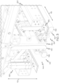
- the forming apparatus 100 includes a frame 110.
- the frame 110 is generally rectangular in shape.
- the frame 110 defines a vertical axis 112, a horizontal axis 114, and a longitudinal axis 116.
- the frame 110 surrounds a carriage 120 having a shape that is generally the same as the frame 110 but is smaller such that the carriage 120 nests within the frame 110.
- the carriage 120 is movably connected to the frame 110 such that it may pivot or rotate along the vertical axis 112 and horizontal axis 114 to accommodate any specific geometry or configuration and achieve a best fit position.
- FIG. 2 and FIG. 3 illustrate an example of a forming apparatus 100.
- the forming apparatus 100 comprises a first stomp foot 130.
- First stomp foot 130 is movably connected to the carriage 120.
- the first stomp foot 130 is movable along the vertical axis 112.
- the first stomp foot 130 may have a flat or a curved design based upon the geometry of the forming tool 310.
- the first stomp foot 130 is controlled by any suitable means and is further configured to press one or more ply 320 of composite material 325 onto a forming surface 308 of a forming tool 310 and hold the one or more ply 320 of composite material 325 in place.
- the first stomp foot 130 movement is controlled by an actuator 147.
- the actuator 147 is a pneumatically actuated forming cylinder 147a.
- the first stomp foot 130 movement is controlled by at least one magnetic switch configured to detect travel and location of the first stomp foot 130 with respect to a forming tool 310.
- the first stomp foot 130 is configured to apply compaction force 350, FIG. 11 , to a forming tool 310.
- the applied compaction force 350 may be variable or may be consistent based upon the geometry of the forming tool 310.
- the forming apparatus 100 comprises a second stomp foot 135.
- the second stomp foot 135 is movably connected to the carriage 120.
- the second stomp foot 135 is movable along the vertical axis 112.
- the second stomp foot 135 may have a flat or a curved design based upon the geometry of the forming tool 310.
- the second stomp foot 135 is controlled by any suitable means and is further configured to press one or more ply 320 of composite material 325 onto a forming surface 308 of a forming tool 310 and hold the one or more ply 320 of composite material 325 in place.
- the second stomp foot 135 movement is controlled by an actuator 147.
- the actuator 147 is a pneumatically actuated forming cylinder 147a.
- the second stomp foot 135 movement is controlled by at least one magnetic switch configured to detect travel and location of the second stomp foot 135 with respect to a forming tool 310.
- the second stomp foot 135 is configured to apply compaction force 350 to a forming tool 310.
- the applied compaction force 350 may be variable or may be consistent based upon the geometry of the forming tool 310.
- the forming apparatus 100 comprises a ply support feature 185.
- Ply support feature 185 may be located below the first stomp foot 130 and the second stomp foot 135.
- Ply support feature 185 may be configured to support one or more ply 320 of composite material 325 prior to initiation of forming.
- Ply support feature 185 may further be configured to prevent the one or more ply 320 of composite material 325 from wrinkling prior to or during forming.
- the ply support feature 185 may be mechanical or may be air driven. In an example, the ply support feature 185 is an air knife.
- the forming apparatus 100 comprises a first swing arm 140.
- the first swing arm 140 is movably connected to the carriage 120.
- the forming apparatus 100 comprises an actuator 147.
- Actuator 147 is configured to move the first swing arm 140 along the vertical axis 112.
- the actuator 147 is a pneumatically actuated forming cylinder 147a.
- a first end effector 145 is movably connected to the first swing arm 140.
- the first end effector 145 comprises a first forming feature 142.
- the first forming feature 142 is an inflatable bladder 146.
- the first forming feature 142 is a forming finger 148, FIG. 11 .
- the first swing arm 140 is configured to pivot along the horizontal axis 114 and the longitudinal axis 116 and apply forming force 330 to a forming surface 308 of a forming tool 310.
- the pivoting capabilities of the first swing arm 140 are advantageous for uniformly applying forming force 330 to a forming surface 308 of the inside of a stringer forming tool 316.
- the forming force 330 averages about 3.57 Kg per linear cm (201bs per linear inch).
- the forming force 330 ranges from about 0.89 Kg per linear cm (5lbs per linear inch) to about 8.92 Kg per linear cm (50lbs per linear inch) based upon material properties and forming tool 310 geometry.
- the forming force 330 applied to the forming surface 308 of the forming tool 310 is dependent upon various factors including geometry of the forming tool 310, the amount of composite material 325 on the forming surface 308 of the forming tool 310, and one or more numerical control program 420.
- the first swing arm 140 includes one or more sensor 410 configured to detect the location and configuration of a forming tool 310.
- the one or more sensor 410 may be in communication with a controller 400.
- the controller 400 is configured to receive data from the one or more sensor 410 and analyze that data to control movement of the second end effector 155.
- the controller may utilize one or more numerical control program 420 in conjunction with the data collected from the one or more sensor 410 to determine proper movement and placement of the second end effector 155.
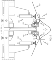
- FIG. 8 illustrates a portion of forming apparatus 100.
- the forming apparatus 100 comprises a second swing arm 150.
- the second swing arm 150 is movably connected to the carriage 120.
- the second swing arm 150 is laterally opposed from said first swing arm 140 relative to the longitudinal axis 116 such that it mirrors the first swing arm 140.
- the second swing arm 150 comprises a second end effector 155 movably connected to the second swing arm 150.
- the second end effector 155 comprises a second forming feature 152.
- the second forming feature 152 is an inflatable bladder 146.
- the second forming feature 152 is a forming finger 148.
- the second swing arm 150 is configured to pivot along the horizontal axis 114 and the longitudinal axis 116 and apply forming force 330 to a forming surface 308 of a forming tool 310 as illustrated in FIG. 9 .
- the pivoting capabilities of the second swing arm 150 are advantageous for uniformly applying forming force 330 to a forming surface 308 of the inside of a stringer forming tool 316.
- the first swing arm 140 and the second swing arm 150 are independently pivotable.
- the forming force 330 averages about 3.57 Kg per linear cm (201bs per linear inch).
- the forming force 330 ranges from about 0.89 Kg per linear cm (5lbs per linear inch) to about 8.92 Kg per linear cm (50lbs per linear inch) based upon material properties and forming tool 310 geometry.
- the forming force 330 applied to the forming surface 308 of the forming tool 310 is dependent upon various factors including geometry of the forming tool 310, the amount of composite material 325 on the forming surface 308 of the forming tool 310, and one or more numerical control program 420.
- the second swing arm 150 includes one or more sensor 410 configured to detect the location and configuration of a forming tool 310.
- the one or more sensor 410 may be in communication with a controller 400.
- the controller 400 is configured to receive data from the one or more sensor 410 and analyze that data to control movement of the second end effector 155.
- the controller may utilize one or more numerical control program 420 in conjunction with the data collected from the one or more sensor 410 to determine proper movement and placement of the second end effector 155.
- the forming apparatus 100 comprises a first plurality 144 of the first end effector 145.
- the first plurality 144 of the first end effector 145 extends along the longitudinal axis 116.
- each individual first end effector 145 of the first plurality 144 of the first end effector 145 is independently movable. This arrangement allows for the first plurality 144 of the first end effector 145 to form a convex, concave, or linear configuration.
- the first plurality 144 of the first end effector 145 includes five of the first end effector 145 that are movably connected to a mounting beam 180.
- the mounting beam 180 is movably connected to the carriage 120 such that it may move along the vertical axis 112 and horizontal axis 114 in accordance with the shape and geometry of a forming tool 310.
- the forming apparatus 100 comprises a second plurality 154 of the second end effector 155.
- the second plurality 154 of the second end effector 155 extends along the longitudinal axis 116 and is laterally opposed from the second plurality 154 of the second end effector 155.
- each individual second end effector 155 of the second plurality 154 of the second end effector 155 is independently movable. This arrangement allows for the second plurality 154 of the second end effector 155 to form a convex, concave, or linear configuration.
- the second plurality 154 of the second end effector 155 includes five of the second end effector 155 that are movably connected to a mounting beam 180.
- the mounting beam 180 is movably connected to the carriage 120 such that it may move along the vertical axis 112 and horizontal axis 114 in accordance with the shape and geometry of a forming tool 310.
- the forming apparatus 100 comprises a protective slip film 160 as illustrated in FIG. 8 .
- the protective slip film 160 may be of any suitable material including a polymer material such as PTFE or FEP.
- the protective slip film 160 is connected to at least one retractable spool 165.
- the retractable spool 165 is configured to provide constant tension to the protective slip film 160.
- the protective slip film 160 is advantageous in prevention of bunching, distorting, or wrinkling of composite material 325 material during the forming process.
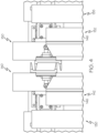
- the forming apparatus 100 includes a pivoting bearing assembly 170, FIG. 2 .
- the forming apparatus 100 may include more than one pivoting bearing assembly 170 that is movably connected to the carriage 120 and a mounting beam 180 via a bearing mount 180a.
- the pivoting bearing assembly 170 is configured to have linear and radial configurations.
- the pivoting bearing assembly 170 allows for adjustments in yaw angle with respect to the first plurality 144 of first end effector 145 and second plurality 154 of the second end effector 155. Adjustments in yaw angle allow for uniform application of compaction force 350 across a forming tool 310, and particularly to a spar forming tool 314.
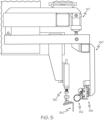
- FIG. 5 , FIG. 6 , and FIG. 7 illustrate an exemplary series of deforming 220 the at least one ply 320 of composite material 325 over the forming surface 308 of the forming tool 310 with a forming apparatus 100.
- FIG. 5 illustrates initiation of the deforming 220 at least one ply 320 of composite material 325 over the forming surface 308 of a stringer forming tool 316.
- the first stomp foot 130 abuts the forming surface 308.
- the first stomp foot 130 is applying compaction force 350 to the forming surface 308.
- First swing arm 140 is generally parallel to the vertical axis 112.
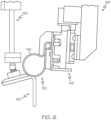
- FIG. 6 illustrates progression of the deforming 220 at least one ply 320 of composite material 325 over the forming surface 308 of a stringer forming tool 316.
- the first swing arm 140 has pivoted across the horizontal axis 114 while uniformly applying compaction force 350 across the forming surface 308.
- the first end effector 145 has also moved to conform to the geometry of the stringer forming tool 316. Movement of the first swing arm 140 and first end effector 145 along the horizontal axis 114 and/or vertical axis 112 may be simultaneous or may occur independently based upon forming tool 310 geometry.
- a controller 400 may utilize one or more numerical control program 420 in conjunction with data collected from one or more sensor 410 to determine proper movement and placement of the first end effector 145 forming feature 142.
- FIG. 7 illustrates further progression of the deforming 220 at least one ply 320 of composite material 325 over the forming surface 308 of a stringer forming tool 316.
- the first swing arm 140 and first end effector 145 have moved across the horizontal axis 114 and down the vertical axis 112 while uniformly applying compaction force 350 across the forming surface 308. Further, the first stomp foot 130 has remained stationary to hold the at least one ply 320 of composite material 325 in place while the deforming 220 occurs.
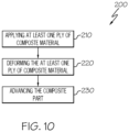
- FIG. 10 illustrates an example of method 200 herein.
- a method 200 for forming a composite part 375 comprises applying 210 at least one ply 320 of composite material 325 over a forming surface 308 of a forming tool 310.
- the method 200 further comprises deforming 220 the at least one ply 320 of composite material 325 over the forming surface 308 of the forming tool 310 with a forming apparatus 100.
- the method 200 further comprises advancing 230 the composite part 375 to a subsequent process.
- the forming apparatus 100 of the method 200 includes a frame 110.
- the frame 110 is generally rectangular in shape.
- the frame 110 defines a vertical axis 112, a horizontal axis 114, and a longitudinal axis 116.
- the frame 110 surrounds a carriage 120 having a shape that is generally the same as the frame 110 but is smaller such that the carriage 120 nests within the frame 110.
- the carriage 120 is movably connected to the frame 110 such that it may pivot or rotate along the vertical axis 112 and horizontal axis 114 to accommodate any specific geometry or configuration and achieve a best fit position.
- the forming apparatus 100 comprises a first stomp foot 130.
- First stomp foot 130 is movably connected to the carriage 120.
- the first stomp foot 130 is movable along the vertical axis 112.
- the first stomp foot 130 may have a flat or a curved design based upon the geometry of the forming tool 310.
- the first stomp foot 130 is controlled by any suitable means and is further configured to press one or more ply 320 of composite material 325 onto a forming surface 308 of a forming tool 310 and hold the one or more ply 320 of composite material 325 in place.
- the first stomp foot 130 movement is controlled by an actuator 147.
- the actuator 147 is a pneumatically actuated forming cylinder 147a.
- the first stomp foot 130 movement is controlled by at least one magnetic switch configured to detect travel and location of the first stomp foot 130 with respect to a forming tool 310.
- the first stomp foot 130 is configured to apply compaction force 350 to a forming tool 310.
- the applied compaction force 350 may be variable or may be consistent based upon the geometry of the forming tool 310.
- the forming apparatus 100 comprises a second stomp foot 135.
- the second stomp foot 135 is movably connected to the carriage 120.
- the second stomp foot 135 is movable along the vertical axis 112.
- the second stomp foot 135 may have a flat or a curved design based upon the geometry of the forming tool 310.
- the second stomp foot 135 is controlled by any suitable means and is further configured to press one or more ply 320 of composite material 325 onto a forming surface 308 of a forming tool 310 and hold the one or more ply 320 of composite material 325 in place.
- the second stomp foot 135 movement is controlled by an actuator 147.
- the actuator 147 is a pneumatically actuated forming cylinder 147a.
- the second stomp foot 135 movement is controlled by at least one magnetic switch configured to detect travel and location of the second stomp foot 135 with respect to a forming tool 310.
- the second stomp foot 135 is configured to apply compaction force 350 to a forming tool 310.
- the applied compaction force 350 may be variable or may be consistent based upon the geometry of the forming tool 310.
- the forming apparatus 100 comprises a ply support feature 185.
- Ply support feature 185 may be located below the first stomp foot 130 and the second stomp foot 135.
- Ply support feature 185 may be configured to support one or more ply 320 of composite material 325 prior to initiation of forming.
- Ply support feature 185 may further be configured to prevent the one or more ply 320 of composite material 325 from wrinkling prior to or during forming.
- the ply support feature 185 may be mechanical or may be air driven. In an example, the ply support feature 185 is an air knife.
- the forming apparatus 100 comprises a first swing arm 140.
- the first swing arm 140 is movably connected to the carriage 120.
- the forming apparatus 100 comprises an actuator 147.
- Actuator 147 is configured to move the first swing arm 140 along the vertical axis 112.
- the actuator 147 is a pneumatically actuated forming cylinder 147a.
- a first end effector 145 is movably connected to the first swing arm 140.
- the first end effector 145 comprises a first forming feature 142.
- the first forming feature 142 is an inflatable bladder 146.
- the first forming feature 142 is a forming finger 148.
- the first swing arm 140 is configured to pivot along the horizontal axis 114 and the longitudinal axis 116 and apply forming force 330 to a forming surface 308 of a forming tool 310.
- the pivoting capabilities of the first swing arm 140 are advantageous for uniformly applying forming force 330 to a forming surface 308 of the inside of a stringer forming tool 316.
- the forming force 330 averages about 3.57 Kg per linear cm (20lbs per linear inch).
- the forming force 330 ranges from about 0.89 Kg per linear cm (5lbs per linear inch) to about 8.92 Kg per linear cm (50lbs per linear inch) based upon material properties and forming tool 310 geometry.
- the forming force 330 applied to the forming surface 308 of the forming tool 310 is dependent upon various factors including geometry of the forming tool 310, the amount of composite material 325 on the forming surface 308 of the forming tool 310, and one or more numerical control program 420.
- the first swing arm 140 includes one or more sensor 410 configured to detect the location and configuration of a forming tool 310.
- the one or more sensor 410 may be in communication with a controller 400.
- the controller 400 is configured to receive data from the one or more sensor 410 and analyze that data to control movement of the second end effector 155.
- the controller may utilize one or more numerical control program 420 in conjunction with the data collected from the one or more sensor 410 to determine proper movement and placement of the second end effector 155.
- the forming apparatus 100 comprises a second swing arm 150.
- the second swing arm 150 is movably connected to the carriage 120.
- the second swing arm 150 is laterally opposed from said first swing arm 140 relative to the longitudinal axis 116 such that it mirrors the first swing arm 140.
- the second swing arm 150 comprises a second end effector 155 movably connected to the second swing arm 150.
- the second end effector 155 comprises a second forming feature 152.
- the second forming feature 152 is an inflatable bladder 146.
- the second forming feature 152 is a forming finger 148.
- the second swing arm 150 is configured to pivot along the horizontal axis 114 and the longitudinal axis 116 and apply forming force 330 to a forming surface 308 of a forming tool 310.
- the pivoting capabilities of the second swing arm 150 are advantageous for uniformly applying forming force 330 to a forming surface 308 of the inside of a stringer forming tool 316.
- the forming force 330 averages about 3.57 Kg per linear cm (20lbs per linear inch).
- the forming force 330 ranges from about 0.89 Kg per linear cm (5lbs per linear inch) to about 8.92 Kg per linear cm (50lbs per linear inch) based upon material properties and forming tool 310 geometry.
- the forming force 330 applied to the forming surface 308 of the forming tool 310 is dependent upon various factors including geometry of the forming tool 310, the amount of composite material 325 on the forming surface 308 of the forming tool 310, and one or more numerical control program 420.
- the second swing arm 150 includes one or more sensor 410 configured to detect the location and configuration of a forming tool 310.
- the one or more sensor 410 may be in communication with a controller 400.
- the controller 400 is configured to receive data from the one or more sensor 410 and analyze that data to control movement of the second end effector 155.
- the controller may utilize one or more numerical control program 420 in conjunction with the data collected from the one or more sensor 410 to determine proper movement and placement of the second end effector 155.
- FIG. 11 illustrates an example of system 300 herein.
- a system 300 is disclosed.
- the system 300 comprises a forming apparatus 100, a forming tool 310, and at least one ply 320 of composite material 325.
- the forming tool 310 is a spar forming tool 314.
- the forming tool 310 is a stringer forming tool 316.
- the forming tool 310 is a hat stringer forming tool 312.
- the forming apparatus 100 of system 300 includes a frame 110.
- the frame 110 is generally rectangular in shape.
- the frame 110 defines a vertical axis 112, a horizontal axis 114, and a longitudinal axis 116.
- the frame 110 surrounds a carriage 120 having a shape that is generally the same as the frame 110 but is smaller such that the carriage 120 nests within the frame 110.
- the carriage 120 is movably connected to the frame 110 such that it may pivot or rotate along the vertical axis 112 and horizontal axis 114 to accommodate any specific geometry or configuration and achieve a best fit position.
- the forming apparatus 100 of the system 300 includes a first stomp foot 130.
- First stomp foot 130 is movably connected to the carriage 120.
- the first stomp foot 130 is movable along the vertical axis 112.
- the first stomp foot 130 may have a flat or a curved design based upon the geometry of the forming tool 310.
- the first stomp foot 130 is controlled by any suitable means and is further configured to press one or more ply 320 of composite material 325 onto a forming surface 308 of a forming tool 310 and hold the one or more ply 320 of composite material 325 in place.
- the first stomp foot 130 movement is controlled by an actuator 147.
- the actuator 147 is a pneumatically actuated forming cylinder 147a.
- the first stomp foot 130 movement is controlled by at least one magnetic switch configured to detect travel and location of the first stomp foot 130 with respect to a forming tool 310.
- the first stomp foot 130 is configured to apply compaction force 350 to a forming tool 310.
- the applied compaction force 350 may be variable or may be consistent based upon the geometry of the forming tool 310.
- the forming apparatus 100 comprises a second stomp foot 135.
- the second stomp foot 135 is movably connected to the carriage 120.
- the second stomp foot 135 is movable along the vertical axis 112.
- the second stomp foot 135 may have a flat or a curved design based upon the geometry of the forming tool 310.
- the second stomp foot 135 is controlled by any suitable means and is further configured to press one or more ply 320 of composite material 325 onto a forming surface 308 of a forming tool 310 and hold the one or more ply 320 of composite material 325 in place.
- the second stomp foot 135 movement is controlled by an actuator 147.
- the actuator 147 is a pneumatically actuated forming cylinder 147a.
- the second stomp foot 135 movement is controlled by at least one magnetic switch configured to detect travel and location of the second stomp foot 135 with respect to a forming tool 310.
- the second stomp foot 135 is configured to apply compaction force 350 to a forming tool 310.
- the applied compaction force 350 may be variable or may be consistent based upon the geometry of the forming tool 310.
- the forming apparatus 100 comprises a ply support feature 185.
- Ply support feature 185 may be located below the first stomp foot 130 and the second stomp foot 135.
- Ply support feature 185 may be configured to support one or more ply 320 of composite material 325 prior to initiation of forming.
- Ply support feature 185 may further be configured to prevent the one or more ply 320 of composite material 325 from wrinkling prior to or during forming.
- the ply support feature 185 may be mechanical or may be air driven. In an example, the ply support feature 185 is an air knife.
- the forming apparatus 100 comprises a first swing arm 140.
- the first swing arm 140 is movably connected to the carriage 120.
- the forming apparatus 100 comprises an actuator 147.
- Actuator 147 is configured to move the first swing arm 140 along the vertical axis 112.
- the actuator 147 is a pneumatically actuated forming cylinder 147a.
- a first end effector 145 is movably connected to the first swing arm 140.
- the first end effector 145 comprises a first forming feature 142.
- the first forming feature 142 is an inflatable bladder 146.
- the first forming feature 142 is a forming finger 148.
- the first swing arm 140 is configured to pivot along the horizontal axis 114 and the longitudinal axis 116 and apply forming force 330 to a forming surface 308 of a forming tool 310.
- the pivoting capabilities of the first swing arm 140 are advantageous for uniformly applying forming force 330 to a forming surface 308 of the inside of a stringer forming tool 316.
- the forming force 330 averages about 3.57 Kg per linear cm (20lbs per linear inch).
- the forming force 330 ranges from about 0.89 Kg per linear cm (5lbs per linear inch) to about 8.92 Kg per linear cm (50lbs per linear inch) based upon material properties and forming tool 310 geometry.
- the forming force 330 applied to the forming surface 308 of the forming tool 310 is dependent upon various factors including geometry of the forming tool 310, the amount of composite material 325 on the forming surface 308 of the forming tool 310, and one or more numerical control program 420.
- the first swing arm 140 includes one or more sensor 410 configured to detect the location and configuration of a forming tool 310.
- the one or more sensor 410 may be in communication with a controller 400.
- the controller 400 is configured to receive data from the one or more sensor 410 and analyze that data to control movement of the second end effector 155.
- the controller may utilize one or more numerical control program 420 in conjunction with the data collected from the one or more sensor 410 to determine proper movement and placement of the second end effector 155.
- the forming apparatus 100 comprises a second swing arm 150.
- the second swing arm 150 is movably connected to the carriage 120.
- the second swing arm 150 is laterally opposed from said first swing arm 140 relative to the longitudinal axis 116 such that it mirrors the first swing arm 140.
- the second swing arm 150 comprises a second end effector 155 movably connected to the second swing arm 150.
- the second end effector 155 comprises a second forming feature 152.
- the second forming feature 152 is an inflatable bladder 146.
- the second forming feature 152 is a forming finger 148.
- the second swing arm 150 is configured to pivot along the horizontal axis 114 and the longitudinal axis 116 and apply forming force 330 to a forming surface 308 of a forming tool 310.
- the pivoting capabilities of the second swing arm 150 are advantageous for uniformly applying forming force 330 to a forming surface 308 of the inside of a stringer forming tool 316.
- the forming force 330 averages about 3.57 Kg per linear cm (20lbs per linear inch).
- the forming force 330 ranges from about 0.89 Kg per linear cm (5lbs per linear inch) to about 8.92 Kg per linear cm (50lbs per linear inch) based upon material properties and forming tool 310 geometry.
- the forming force 330 applied to the forming surface 308 of the forming tool 310 is dependent upon various factors including geometry of the forming tool 310, the amount of composite material 325 on the forming surface 308 of the forming tool 310, and one or more numerical control program 420.
- the second swing arm 150 includes one or more sensor 410 configured to detect the location and configuration of a forming tool 310.
- the one or more sensor 410 may be in communication with a controller 400.
- the controller 400 is configured to receive data from the one or more sensor 410 and analyze that data to control movement of the second end effector 155.
- the controller may utilize one or more numerical control program 420 in conjunction with the data collected from the one or more sensor 410 to determine proper movement and placement of the second end effector 155.
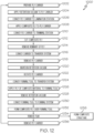
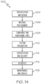
- FIG. 12 illustrates a flowchart of a manufacturing method 1000.
- a manufacturing method 1000 of fabricating a composite part 375 comprises various steps.
- the manufacturing method 1000 includes conveying a ply carrier 604 to a lamination system 612 using a carrier transfer device 610.
- the manufacturing method 1000 includes selectively applying at least one ply 320 of composite material 325 to a ply support surface 608 of the ply carrier 604 using the lamination system 612.
- the manufacturing method 1000 includes conveying the ply carrier 604 from the lamination system 612 to a transfer system 616 using the carrier transfer device 610.
- the manufacturing method 1000 includes the step of removing the ply carrier 604 from the carrier transfer device 610 and applying the at least one ply 320 of composite material 325 to at least a portion of a forming surface 308 of a forming tool 310 using the transfer system 616.
- the manufacturing method 1000 includes the step of forming the at least one ply 320 of composite material 325 over the at least a portion of the forming surface 308 of the forming tool 310 using a forming system 622.
- the forming system 622 comprises a forming apparatus 100.
- the manufacturing method 1000 includes a step of (block 1002) preparing the ply carrier 604, see FIG. 1 .
- the manufacturing method 1000 includes a step of (block 1004) selectively applying the retention vacuum to retain the protective slip film 160 on the base plate 124 using the carrier transfer device 610.
- the manufacturing method 1000 includes a step of (block 1006) conveying the ply carrier 604 to the lamination system 612 using the carrier transfer device 610.
- the manufacturing method 1000 includes a step of (block 1008) selectively applying the ply 320 to the ply support surface 608 of the ply carrier 604 using the lamination system 612.
- the manufacturing method 1000 includes a step of (block 1010) conveying the ply carrier 604 from the lamination system 612 to the trim system 614 using the carrier transfer device 610. In one or more examples, the manufacturing method 1000 includes a step of (block 1012) selectively cutting the ply 320 into the predetermined shape using the trim system 614.
- the manufacturing method 1000 includes a step of (block 1014) removing a remnant of the at least one ply 320 from the ply support surface 608 using the scrap removal system 642, after the step of (block 1012) selectively cutting the at least one ply 320.
- the manufacturing method 1000 includes a step of selectively removing the retention vacuum from select areas of the protective slip film 160 using the carrier transfer device 610.
- the manufacturing method 1000 also includes a step of (block 1016) conveying the ply carrier 604 from the trim system 614 to the transfer system 616 using the carrier transfer device 610.
- the manufacturing method 1000 includes a step of (block 1018) removing the ply carrier 604 from the carrier transfer device 610 and a step of (block 1022) reorienting (e.g., rotating) the ply carrier 604 using the transfer system 616.
- the manufacturing method 1000 includes a step of (block 1020) maintaining the retention vacuum to retain the protective slip film 160 on the base plate 124 using the transfer system 616.
- the manufacturing method 1000 includes a step of (block 1024) conveying the forming tool 310 to the transfer system 616 using the tool transfer device 646.
- the manufacturing method 1000 includes a step of (block 1026) applying the ply 320 to at least a portion of the forming surface 308 of the forming tool 310 using the transfer system 616.
- the manufacturing method 1000 includes a step of releasing the protective slip film 160 from the base plate 124 and a step of removing the ply carrier 604 (e.g., the base plate 124) from the forming tool 310 using the transfer system 616, , after the step of (block 1026) applying the ply 320 to at least a portion of the forming surface 308 of the forming tool 310.
- the manufacturing method 1000 includes a step of (block 1028) selectively removing the retention vacuum to release the protective slip film 160 from the base plate 124 while retaining the base plate 124 using the transfer system 616.
- the manufacturing method 1000 includes a step of (block 1030) conveying the forming tool 310 from the transfer system 616 to the forming system 622 using the tool transfer device 646. In one or more examples, the manufacturing method 1000 includes a step of (block 1032) forming the ply 320 over the at least a portion of the forming surface 308 of the forming tool 310 using the forming system 622. In one or more examples, the manufacturing method 1000 includes a step of (block 1034) removing the protective slip film 160 from the ply 320 using the film removal system 660.
- the manufacturing method 1000 includes a step of (block 1036) returning the ply carrier 604 (e.g., the base plate 124) to the carrier transfer device 610 using the transfer system 616.
- the above operations are repeated a number of times to fully form the composite structure (block 1038), at which point the process terminates.
- the forming apparatus 100 of the manufacturing method 1000 includes a frame 110.
- the frame 110 is generally rectangular in shape.
- the frame 110 defines a vertical axis 112, a horizontal axis 114, and a longitudinal axis 116.
- the frame 110 surrounds a carriage 120 having a shape that is generally the same as the frame 110 but is smaller such that the carriage 120 nests within the frame 110.
- the carriage 120 is movably connected to the frame 110 such that it may pivot or rotate along the vertical axis 112 and horizontal axis 114 to accommodate any specific geometry or configuration and achieve a best fit position.
- the forming apparatus 100 includes a first stomp foot 130.
- First stomp foot 130 is movably connected to the carriage 120.
- the first stomp foot 130 is movable along the vertical axis 112.
- the first stomp foot 130 may have a flat or a curved design based upon the geometry of the forming tool 310.
- the first stomp foot 130 is controlled by any suitable means and is further configured to press one or more ply 320 of composite material 325 onto a forming surface 308 of a forming tool 310 and hold the one or more ply 320 of composite material 325 in place.
- the first stomp foot 130 movement is controlled by an actuator 147.
- the actuator 147 is a pneumatically actuated forming cylinder 147a.
- the first stomp foot 130 movement is controlled by at least one magnetic switch configured to detect travel and location of the first stomp foot 130 with respect to a forming tool 310.
- the first stomp foot 130 is configured to apply compaction force 350 to a forming tool 310.
- the applied compaction force 350 may be variable or may be consistent based upon the geometry of the forming tool 310.
- the forming apparatus 100 comprises a second stomp foot 135.
- the second stomp foot 135 is movably connected to the carriage 120.
- the second stomp foot 135 is movable along the vertical axis 112.
- the second stomp foot 135 may have a flat or a curved design based upon the geometry of the forming tool 310.
- the second stomp foot 135 is controlled by any suitable means and is further configured to press one or more ply 320 of composite material 325 onto a forming surface 308 of a forming tool 310 and hold the one or more ply 320 of composite material 325 in place.
- the second stomp foot 135 movement is controlled by an actuator 147.
- the actuator 147 is a pneumatically actuated forming cylinder 147a.
- the second stomp foot 135 movement is controlled by at least one magnetic switch configured to detect travel and location of the second stomp foot 135 with respect to a forming tool 310.
- the second stomp foot 135 is configured to apply compaction force 350 to a forming tool 310.
- the applied compaction force 350 may be variable or may be consistent based upon the geometry of the forming tool 310.
- the forming apparatus 100 comprises a ply support feature 185.
- Ply support feature 185 may be located below the first stomp foot 130 and the second stomp foot 135.
- Ply support feature 185 may be configured to support one or more ply 320 of composite material 325 prior to initiation of forming.
- Ply support feature 185 may further be configured to prevent the one or more ply 320 of composite material 325 from wrinkling prior to or during forming.
- the ply support feature 185 may be mechanical or may be air driven. In an example, the ply support feature 185 is an air knife.
- the forming apparatus 100 comprises a first swing arm 140.
- the first swing arm 140 is movably connected to the carriage 120.
- the forming apparatus 100 comprises an actuator 147.
- Actuator 147 is configured to move the first swing arm 140 along the vertical axis 112.
- the actuator 147 is a pneumatically actuated forming cylinder 147a.
- a first end effector 145 is movably connected to the first swing arm 140.
- the first end effector 145 comprises a first forming feature 142.
- the first forming feature 142 is an inflatable bladder 146.
- the first forming feature 142 is a forming finger 148.
- the first swing arm 140 is configured to pivot along the horizontal axis 114 and the longitudinal axis 116 and apply forming force 330 to a forming surface 308 of a forming tool 310.
- the pivoting capabilities of the first swing arm 140 are advantageous for uniformly applying forming force 330 to a forming surface 308 of the inside of a stringer forming tool 316.
- the forming force 330 averages about 3.57 Kg per linear cm (20lbs per linear inch).
- the forming force 330 ranges from about 0.89 Kg per linear cm (5lbs per linear inch) to about 8.92 Kg per linear cm (50lbs per linear inch) based upon material properties and forming tool 310 geometry.
- the forming force 330 applied to the forming surface 308 of the forming tool 310 is dependent upon various factors including geometry of the forming tool 310, the amount of composite material 325 on the forming surface 308 of the forming tool 310, and one or more numerical control program 420.
- the first swing arm 140 includes one or more sensor 410 configured to detect the location and configuration of a forming tool 310.
- the one or more sensor 410 may be in communication with a controller 400.
- the controller 400 is configured to receive data from the one or more sensor 410 and analyze that data to control movement of the second end effector 155.
- the controller may utilize one or more numerical control program 420 in conjunction with the data collected from the one or more sensor 410 to determine proper movement and placement of the second end effector 155.
- the forming apparatus 100 comprises a second swing arm 150.
- the second swing arm 150 is movably connected to the carriage 120.
- the second swing arm 150 is laterally opposed from said first swing arm 140 relative to the longitudinal axis 116 such that it mirrors the first swing arm 140.
- the second swing arm 150 comprises a second end effector 155 movably connected to the second swing arm 150.
- the second end effector 155 comprises a second forming feature 152.
- the second forming feature 152 is an inflatable bladder 146.
- the second forming feature 152 is a forming finger 148.
- the second swing arm 150 is configured to pivot along the horizontal axis 114 and the longitudinal axis 116 and apply forming force 330 to a forming surface 308 of a forming tool 310.
- the pivoting capabilities of the second swing arm 150 are advantageous for uniformly applying forming force 330 to a forming surface 308 of the inside of a stringer forming tool 316.
- the forming force 330 averages about 3.57 Kg per linear cm (20lbs per linear inch).
- the forming force 330 ranges from about 0.89 Kg per linear cm (5lbs per linear inch) to about 8.92 Kg per linear cm (50lbs per linear inch) based upon material properties and forming tool 310 geometry.
- the forming force 330 applied to the forming surface 308 of the forming tool 310 is dependent upon various factors including geometry of the forming tool 310, the amount of composite material 325 on the forming surface 308 of the forming tool 310, and one or more numerical control program 420.
- the second swing arm 150 includes one or more sensor 410 configured to detect the location and configuration of a forming tool 310.
- the one or more sensor 410 may be in communication with a controller 400.
- the controller 400 is configured to receive data from the one or more sensor 410 and analyze that data to control movement of the second end effector 155.
- the controller may utilize one or more numerical control program 420 in conjunction with the data collected from the one or more sensor 410 to determine proper movement and placement of the second end effector 155.
- the aircraft manufacturing and service method 1100 may include specification and design 1104 of the aircraft 1102 and material procurement 1106.
- component/subassembly manufacturing 1108 and system integration 1110 of the aircraft 1102 takes place.
- the aircraft 1102 may go through certification and delivery 1112 in order to be placed in service 1114.
- routine maintenance and service 1116 which may also include modification, reconfiguration, refurbishment and the like.
- Each of the steps of the aircraft manufacturing and service method 1100 may be performed or carried out by a system integrator, a third party, and/or an operator (e.g., a customer).
- a system integrator may include without limitation any number of aircraft manufacturers and major-system subcontractors
- a third party may include without limitation any number of venders, subcontractors, and suppliers
- an operator may be an airline, leasing company, military entity, service organization, and so on.
- the aircraft 1102 produced by the example aircraft manufacturing and service method 1100 may include an airframe 1118 with a plurality of systems 1120 and an interior 1122.
- the plurality of systems 1120 may include one or more of a propulsion system 1124, an electrical system 1126, a hydraulic system 1128, and an environmental system 1130. Any number of other systems may be included.
- the disclosed methods and systems may be employed during any one or more of the stages of the aircraft manufacturing and service method 1100.
- components or subassemblies corresponding to component/subassembly manufacturing 1108, system integration 1110 and/or maintenance and service 1116 may be assembled using the disclosed methods and systems.
- the airframe 1118 may be constructed using the disclosed methods and systems.
- one or more apparatus examples, method examples, or a combination thereof may be utilized during component/subassembly manufacturing 1108 and/or system integration 1110, for example, by substantially expediting assembly of or reducing the cost of an aircraft 1102, such as the airframe 1118 and/or the interior 1122.
- one or more of system examples, method examples, or a combination thereof may be utilized while the aircraft 1102 is in service, for example and without limitation, to maintenance and service 1116.
- aspects of disclosed examples may be implemented in software, hardware, firmware, or a combination thereof.
- the various elements of the system may be implemented as a computer program product tangibly embodied in a machine-readable storage device for execution by a processor.
- Various steps of examples may be performed by a computer processor executing a program tangibly embodied on a computer-readable medium to perform functions by operating on input and generating output.
- the computer-readable medium may be, for example, a memory, a transportable medium such as a compact disk or a flash drive, such that a computer program embodying aspects of the disclosed examples can be loaded onto a computer.
Landscapes
- Engineering & Computer Science (AREA)
- Mechanical Engineering (AREA)
- Chemical & Material Sciences (AREA)
- Composite Materials (AREA)
- Robotics (AREA)
- Moulding By Coating Moulds (AREA)
Claims (13)
- Formgebungsvorrichtung (100), die aufweist:einen Rahmen (110), der eine vertikale Achse (112), eine horizontale Achse (114) und eine Längsachse (116) definiert;einen Wagen (120), der beweglich mit dem Rahmen (110) verbunden ist;einen ersten Stampffuß (130), der beweglich mit dem Wagen (120) verbunden ist;einen zweiten Stampffuß (135), der beweglich mit dem Wagen (120) verbunden ist;einen ersten Schwenkarm (140), der beweglich mit dem Wagen (120) verbunden ist;einen zweiten Schwenkarm (150), der beweglich mit dem Wagen (120) verbunden ist, wobei der zweite Schwenkarm (150) lateral dem ersten Schwenkarm (140) relativ zur Längsachse (116) gegenüberliegt;ein Lagenstützmerkmal (185), das unterhalb des ersten Stampffußes (130) und des zweiten Stampffußes (135) lokalisiert ist;einen ersten Endeffektor (145), der beweglich mit dem ersten Schwenkarm (140) verbunden ist;einen zweiten Endeffektor (155), der beweglich mit dem zweiten Schwenkarm (150) verbunden ist;wobei der erste Endeffektor (145) ein erstes Formgebungsmerkmal (142) aufweist;wobei der zweite Endeffektor (155) ein zweites Formgebungsmerkmal (152) aufweist; undwobei der erste Schwenkarm (140) und der zweite Schwenkarm (150) eingerichtet sind, entlang der horizontalen Achse (114) und der Längsachse (116) verschwenkt zu werden und eine Formgebungskraft (330) auszuüben.
- Formgebungsvorrichtung (100) nach Anspruch 1, wobei das erste Formgebungsmerkmal (142) eine aufblasbare Blase (146) ist.
- Formgebungsvorrichtung (100) nach Anspruch 1, wobei das zweite Formgebungsmerkmal (152) eine aufblasbare Blase (146) ist.
- Formgebungsvorrichtung (100) nach einem der Ansprüche 1-3, wobei der erste Stampffuß (130) und der zweite Stampffuß (135) eingerichtet sind, sich entlang der vertikalen Achse (112) zu bewegen und eine Verdichtungskraft (350) auszuüben.
- Formgebungsvorrichtung (100) nach Anspruch 1, wobei der erste Schwenkarm (140) und der zweite Schwenkarm (150) eingerichtet sind, unabhängig vom Wagen (120) verschwenkt zu werden.
- Formgebungsvorrichtung (100) nach einem der Ansprüche 1-5, die einen Aktuator (147) aufweist, der eingerichtet ist, den ersten Schwenkarm (140) entlang der vertikalen Achse (112) zu bewegen.
- Formgebungsvorrichtung (100 nach Anspruch 1, wobei die Formgebungskraft (330) im Durchschnitt ungefähr 3,57 kg/cm (20 lbs/inch) beträgt.
- Formgebungsvorrichtung (100) nach einem der Ansprüche 1-7, die eine Schutzrutschfolie aufweist.
- Verfahren (200) zum Formen eines Verbundteils, wobei das Verfahren (200) aufweist:Applizieren (210) zumindest einer Lage (320) eines Verbundmaterials (325) über eine Formgebungsfläche (308) eines Formgebungswerkzeugs (310); undVerformen (220) der zumindest einen Lage (320) aus Verbundmaterial (325) über der Formgebungsfläche (308) des Formgebungswerkzeugs (310) mit der Formgebungsvorrichtung (100) nach Anspruch 1.
- Verfahren (200) nach Anspruch 9, wobei das Formgebungswerkzeug (310) ein Holmformwerkzeug (314), ein Längsstreben-Formwerkzeug (316) oder ein Hutlängsstreben-Formwerkzeug (312) ist.
- System (300), das aufweist:die Formgebungsvorrichtung (100) nach Anspruch 1;ein Formgebungswerkzeug (310); undzumindest eine Lage (320) eines Verbundmaterial (325).
- System (300) nach Anspruch 11, wobei das Formgebungswerkzeug (310) ein Holmformwerkzeug (314), ein Längsstreben-Formwerkzeug (316) oder ein Hutlängsstreben-Formwerkzeug (312) ist.
- Verbundherstellungssystem (600) zum Herstellen eines Verbundteils (375), wobei das Verbundherstellungssystem (600) aufweist:einen Lagenträger (604), der eine Lagenstützfläche (608) aufweist, die zum Stützen von zumindest einer Lage (320) eines Verbundmaterials (325) eingerichtet ist;eine Trägertransfervorrichtung (610), die eingerichtet ist, den Lagenträger (604) zu fördern;ein Laminierungssystem (612), das eingerichtet ist, wahlweise die zumindest eine Lage (320) aus Verbundmaterial (325) auf der Lagenstützfläche (608) des Lagenträgers (604) zu applizieren;ein Transfersystem (616), das eingerichtet ist, den Lagenträger (604) aus der Trägertransfervorrichtung (610) zu entfernen und die zumindest eine Lage (320) aus Verbundmaterial (325) auf zumindest einem Teil einer Formgebungsfläche (308) eines Formgebungswerkzeugs (310) zu applizieren; undein Formgebungssystem (622), das eingerichtet ist, die zumindest eine Lage (320) aus Verbundmaterial (325) über den zumindest einen Teil der Formgebungsfläche (308) des Formgebungswerkzeugs (310) zu formen, wobei das Formgebungssystem (622) aufweist:
die Formgebungsvorrichtung (100) nach Anspruch 1.
Applications Claiming Priority (1)
| Application Number | Priority Date | Filing Date | Title |
|---|---|---|---|
| US202063122021P | 2020-12-07 | 2020-12-07 |
Publications (2)
| Publication Number | Publication Date |
|---|---|
| EP4008535A1 EP4008535A1 (de) | 2022-06-08 |
| EP4008535B1 true EP4008535B1 (de) | 2024-01-10 |
Family
ID=78621735
Family Applications (1)
| Application Number | Title | Priority Date | Filing Date |
|---|---|---|---|
| EP21208131.9A Active EP4008535B1 (de) | 2020-12-07 | 2021-11-15 | Vorrichtung, verfahren und system zur formen |
Country Status (3)
| Country | Link |
|---|---|
| US (1) | US20220176654A1 (de) |
| EP (1) | EP4008535B1 (de) |
| CN (1) | CN114589935A (de) |
Family Cites Families (11)
| Publication number | Priority date | Publication date | Assignee | Title |
|---|---|---|---|---|
| US6814916B2 (en) * | 2002-08-30 | 2004-11-09 | The Boeing Company | Forming method for composites |
| US8936695B2 (en) * | 2007-07-28 | 2015-01-20 | The Boeing Company | Method for forming and applying composite layups having complex geometries |
| US20100269979A1 (en) * | 2009-04-27 | 2010-10-28 | Spirit Aerosystems, Inc. | Bladder pressure bonding apparatus |
| DE102011050099B4 (de) * | 2011-05-04 | 2014-06-26 | Benteler Sgl Gmbh & Co. Kg | Drapierwerkzeug sowie Verfahren zum Herstellen eines Faserverbundwerkstoffbauteils |
| US8997642B2 (en) * | 2011-08-08 | 2015-04-07 | The Boeing Company | Method for transporting, placing and compacting composite stiffeners |
| US9663247B2 (en) * | 2015-02-27 | 2017-05-30 | The Boeing Company | Systems, methods, and vacuum chucks for transferring flexible elongate bodies |
| US10086596B2 (en) * | 2015-03-12 | 2018-10-02 | The Boeing Company | Apparatus and method for automated layup of composite structures |
| US10843416B2 (en) * | 2015-05-11 | 2020-11-24 | Gulfstream Aerospace Corporation | Composite reinforcement structures and aircraft assemblies comprising composite reinforcement structures |
| US10800111B2 (en) * | 2015-06-16 | 2020-10-13 | The Boeing Company | Composite structure fabrication systems and methods |
| US10456960B2 (en) * | 2015-07-24 | 2019-10-29 | The Boeing Company | Systems and methods for incrementally forming a composite part |
| US11014315B2 (en) * | 2017-05-03 | 2021-05-25 | The Boeing Company | Compacted stringer packages |
-
2021
- 2021-10-20 US US17/505,832 patent/US20220176654A1/en active Pending
- 2021-11-15 EP EP21208131.9A patent/EP4008535B1/de active Active
- 2021-12-07 CN CN202111484834.0A patent/CN114589935A/zh active Pending
Also Published As
| Publication number | Publication date |
|---|---|
| EP4008535A1 (de) | 2022-06-08 |
| US20220176654A1 (en) | 2022-06-09 |
| CN114589935A (zh) | 2022-06-07 |
Similar Documents
| Publication | Publication Date | Title |
|---|---|---|
| JP5806930B2 (ja) | 輪郭に合致した複合構造物を生産する方法 | |
| US11565485B2 (en) | System, method, and apparatus for use in ply compaction in forming a composite structure | |
| JP2017052267A (ja) | 起伏のある補強材を形成するための方法及び装置 | |
| US11865825B2 (en) | System, method, and apparatus for use in ply compaction in forming a composite structure | |
| US11969957B2 (en) | System, method, and apparatus for use in forming a composite structure | |
| US11685128B2 (en) | System and method for fabricating a composite structure | |
| CN110861321B (zh) | 成型伸长复合结构的成形 | |
| EP4008535B1 (de) | Vorrichtung, verfahren und system zur formen | |
| US11964442B2 (en) | Forming apparatus, method, and system | |
| US11826970B2 (en) | Forming apparatus, method, and system | |
| EP4000887A1 (de) | Verfahren und vorrichtung zum platzieren von mehrspurigen faserstrangen | |
| US11806947B2 (en) | Forming system and method for forming a contoured composite structure | |
| CN111347752A (zh) | 层板输送和压实设备及其方法 | |
| US11951698B2 (en) | Composite charge positioning system | |
| EP4140712A1 (de) | Verbundformungsapparat, verfahren und systeme | |
| EP4140683A1 (de) | Formgerät, verfahren und systeme | |
| US11433575B2 (en) | Charge shaping system and apparatus | |
| NL2027407B1 (en) | Multi-lane tows for use with ply-by-ply forming machines | |
| EP4011588A2 (de) | Platzierung von vorformlingen für strebenabschnitte auf einem vorformling für ein tragflächenelement | |
| NL2027406B1 (en) | Multi-lane tows for use with ply-by-ply forming machines | |
| US11780181B2 (en) | Multi-lane tows for use with ply-by-ply forming machines |
Legal Events
| Date | Code | Title | Description |
|---|---|---|---|
| PUAI | Public reference made under article 153(3) epc to a published international application that has entered the european phase |
Free format text: ORIGINAL CODE: 0009012 |
|
| STAA | Information on the status of an ep patent application or granted ep patent |
Free format text: STATUS: THE APPLICATION HAS BEEN PUBLISHED |
|
| AK | Designated contracting states |
Kind code of ref document: A1 Designated state(s): AL AT BE BG CH CY CZ DE DK EE ES FI FR GB GR HR HU IE IS IT LI LT LU LV MC MK MT NL NO PL PT RO RS SE SI SK SM TR |
|
| STAA | Information on the status of an ep patent application or granted ep patent |
Free format text: STATUS: REQUEST FOR EXAMINATION WAS MADE |
|
| 17P | Request for examination filed |
Effective date: 20221202 |
|
| RBV | Designated contracting states (corrected) |
Designated state(s): AL AT BE BG CH CY CZ DE DK EE ES FI FR GB GR HR HU IE IS IT LI LT LU LV MC MK MT NL NO PL PT RO RS SE SI SK SM TR |
|
| RAP3 | Party data changed (applicant data changed or rights of an application transferred) |
Owner name: THE BOEING COMPANY |
|
| GRAP | Despatch of communication of intention to grant a patent |
Free format text: ORIGINAL CODE: EPIDOSNIGR1 |
|
| STAA | Information on the status of an ep patent application or granted ep patent |
Free format text: STATUS: GRANT OF PATENT IS INTENDED |
|
| RIC1 | Information provided on ipc code assigned before grant |
Ipc: B29C 43/36 20060101ALN20230417BHEP Ipc: B29C 70/38 20060101ALI20230417BHEP Ipc: B29D 99/00 20100101ALI20230417BHEP Ipc: B29C 70/54 20060101AFI20230417BHEP |
|
| INTG | Intention to grant announced |
Effective date: 20230517 |
|
| GRAJ | Information related to disapproval of communication of intention to grant by the applicant or resumption of examination proceedings by the epo deleted |
Free format text: ORIGINAL CODE: EPIDOSDIGR1 |
|
| STAA | Information on the status of an ep patent application or granted ep patent |
Free format text: STATUS: REQUEST FOR EXAMINATION WAS MADE |
|
| INTC | Intention to grant announced (deleted) | ||
| GRAP | Despatch of communication of intention to grant a patent |
Free format text: ORIGINAL CODE: EPIDOSNIGR1 |
|
| STAA | Information on the status of an ep patent application or granted ep patent |
Free format text: STATUS: GRANT OF PATENT IS INTENDED |
|
| RIC1 | Information provided on ipc code assigned before grant |
Ipc: B29C 43/36 20060101ALN20230919BHEP Ipc: B29C 70/38 20060101ALI20230919BHEP Ipc: B29D 99/00 20100101ALI20230919BHEP Ipc: B29C 70/54 20060101AFI20230919BHEP |
|
| INTG | Intention to grant announced |
Effective date: 20231010 |
|
| GRAS | Grant fee paid |
Free format text: ORIGINAL CODE: EPIDOSNIGR3 |
|
| GRAA | (expected) grant |
Free format text: ORIGINAL CODE: 0009210 |
|
| STAA | Information on the status of an ep patent application or granted ep patent |
Free format text: STATUS: THE PATENT HAS BEEN GRANTED |
|
| AK | Designated contracting states |
Kind code of ref document: B1 Designated state(s): AL AT BE BG CH CY CZ DE DK EE ES FI FR GB GR HR HU IE IS IT LI LT LU LV MC MK MT NL NO PL PT RO RS SE SI SK SM TR |
|
| REG | Reference to a national code |
Ref country code: GB Ref legal event code: FG4D |
|
| REG | Reference to a national code |
Ref country code: CH Ref legal event code: EP |
|
| REG | Reference to a national code |
Ref country code: DE Ref legal event code: R096 Ref document number: 602021008508 Country of ref document: DE |
|
| REG | Reference to a national code |
Ref country code: IE Ref legal event code: FG4D |
|
| P01 | Opt-out of the competence of the unified patent court (upc) registered |
Effective date: 20240109 |
|
| REG | Reference to a national code |
Ref country code: LT Ref legal event code: MG9D |
|
| REG | Reference to a national code |
Ref country code: NL Ref legal event code: MP Effective date: 20240110 |