EP4008523A1 - Method and device for layered construction of a component made from photopolymerisable material - Google Patents
Method and device for layered construction of a component made from photopolymerisable material Download PDFInfo
- Publication number
- EP4008523A1 EP4008523A1 EP20020586.2A EP20020586A EP4008523A1 EP 4008523 A1 EP4008523 A1 EP 4008523A1 EP 20020586 A EP20020586 A EP 20020586A EP 4008523 A1 EP4008523 A1 EP 4008523A1
- Authority
- EP
- European Patent Office
- Prior art keywords
- component
- photopolymerizable
- layer
- component layer
- material removal
- Prior art date
- Legal status (The legal status is an assumption and is not a legal conclusion. Google has not performed a legal analysis and makes no representation as to the accuracy of the status listed.)
- Granted
Links
- 239000000463 material Substances 0.000 title claims abstract description 321
- 238000010276 construction Methods 0.000 title claims abstract description 47
- 238000000034 method Methods 0.000 title claims abstract description 41
- 230000015572 biosynthetic process Effects 0.000 claims abstract description 7
- 239000000919 ceramic Substances 0.000 claims abstract description 6
- 239000000945 filler Substances 0.000 claims abstract description 4
- 239000011347 resin Substances 0.000 claims abstract description 4
- 229920005989 resin Polymers 0.000 claims abstract description 4
- 239000002250 absorbent Substances 0.000 claims description 20
- 230000002745 absorbent Effects 0.000 claims description 20
- 239000002245 particle Substances 0.000 claims description 14
- 239000007788 liquid Substances 0.000 claims description 11
- 230000008569 process Effects 0.000 claims description 9
- 239000002904 solvent Substances 0.000 claims description 7
- 239000012530 fluid Substances 0.000 claims description 2
- 230000003287 optical effect Effects 0.000 claims description 2
- 238000004140 cleaning Methods 0.000 abstract 2
- 101150114468 TUB1 gene Proteins 0.000 description 6
- 230000007246 mechanism Effects 0.000 description 5
- 239000001913 cellulose Substances 0.000 description 4
- 229920002678 cellulose Polymers 0.000 description 4
- 238000004519 manufacturing process Methods 0.000 description 3
- 239000000654 additive Substances 0.000 description 2
- 230000000996 additive effect Effects 0.000 description 2
- 238000013459 approach Methods 0.000 description 2
- 230000008901 benefit Effects 0.000 description 2
- 238000009826 distribution Methods 0.000 description 2
- 238000001459 lithography Methods 0.000 description 2
- 238000012805 post-processing Methods 0.000 description 2
- 238000012545 processing Methods 0.000 description 2
- 229920006395 saturated elastomer Polymers 0.000 description 2
- 230000009471 action Effects 0.000 description 1
- 230000001464 adherent effect Effects 0.000 description 1
- 239000000969 carrier Substances 0.000 description 1
- 230000008859 change Effects 0.000 description 1
- 238000012864 cross contamination Methods 0.000 description 1
- 230000006866 deterioration Effects 0.000 description 1
- 238000011161 development Methods 0.000 description 1
- 238000007598 dipping method Methods 0.000 description 1
- 230000000694 effects Effects 0.000 description 1
- 239000004744 fabric Substances 0.000 description 1
- 239000000835 fiber Substances 0.000 description 1
- 239000011888 foil Substances 0.000 description 1
- 238000007654 immersion Methods 0.000 description 1
- 239000002184 metal Substances 0.000 description 1
- 239000013528 metallic particle Substances 0.000 description 1
- 239000003361 porogen Substances 0.000 description 1
- 238000000275 quality assurance Methods 0.000 description 1
- 238000005096 rolling process Methods 0.000 description 1
- 239000007921 spray Substances 0.000 description 1
- 238000012549 training Methods 0.000 description 1
- 238000012546 transfer Methods 0.000 description 1
Images


Classifications
-
- B—PERFORMING OPERATIONS; TRANSPORTING
- B29—WORKING OF PLASTICS; WORKING OF SUBSTANCES IN A PLASTIC STATE IN GENERAL
- B29C—SHAPING OR JOINING OF PLASTICS; SHAPING OF MATERIAL IN A PLASTIC STATE, NOT OTHERWISE PROVIDED FOR; AFTER-TREATMENT OF THE SHAPED PRODUCTS, e.g. REPAIRING
- B29C64/00—Additive manufacturing, i.e. manufacturing of three-dimensional [3D] objects by additive deposition, additive agglomeration or additive layering, e.g. by 3D printing, stereolithography or selective laser sintering
- B29C64/10—Processes of additive manufacturing
- B29C64/188—Processes of additive manufacturing involving additional operations performed on the added layers, e.g. smoothing, grinding or thickness control
-
- B08B1/143—
-
- B08B1/30—
-
- B—PERFORMING OPERATIONS; TRANSPORTING
- B22—CASTING; POWDER METALLURGY
- B22F—WORKING METALLIC POWDER; MANUFACTURE OF ARTICLES FROM METALLIC POWDER; MAKING METALLIC POWDER; APPARATUS OR DEVICES SPECIALLY ADAPTED FOR METALLIC POWDER
- B22F10/00—Additive manufacturing of workpieces or articles from metallic powder
- B22F10/10—Formation of a green body
- B22F10/12—Formation of a green body by photopolymerisation, e.g. stereolithography [SLA] or digital light processing [DLP]
-
- B—PERFORMING OPERATIONS; TRANSPORTING
- B22—CASTING; POWDER METALLURGY
- B22F—WORKING METALLIC POWDER; MANUFACTURE OF ARTICLES FROM METALLIC POWDER; MAKING METALLIC POWDER; APPARATUS OR DEVICES SPECIALLY ADAPTED FOR METALLIC POWDER
- B22F12/00—Apparatus or devices specially adapted for additive manufacturing; Auxiliary means for additive manufacturing; Combinations of additive manufacturing apparatus or devices with other processing apparatus or devices
- B22F12/30—Platforms or substrates
- B22F12/37—Rotatable
-
- B—PERFORMING OPERATIONS; TRANSPORTING
- B29—WORKING OF PLASTICS; WORKING OF SUBSTANCES IN A PLASTIC STATE IN GENERAL
- B29C—SHAPING OR JOINING OF PLASTICS; SHAPING OF MATERIAL IN A PLASTIC STATE, NOT OTHERWISE PROVIDED FOR; AFTER-TREATMENT OF THE SHAPED PRODUCTS, e.g. REPAIRING
- B29C64/00—Additive manufacturing, i.e. manufacturing of three-dimensional [3D] objects by additive deposition, additive agglomeration or additive layering, e.g. by 3D printing, stereolithography or selective laser sintering
- B29C64/10—Processes of additive manufacturing
- B29C64/106—Processes of additive manufacturing using only liquids or viscous materials, e.g. depositing a continuous bead of viscous material
- B29C64/124—Processes of additive manufacturing using only liquids or viscous materials, e.g. depositing a continuous bead of viscous material using layers of liquid which are selectively solidified
-
- B—PERFORMING OPERATIONS; TRANSPORTING
- B29—WORKING OF PLASTICS; WORKING OF SUBSTANCES IN A PLASTIC STATE IN GENERAL
- B29C—SHAPING OR JOINING OF PLASTICS; SHAPING OF MATERIAL IN A PLASTIC STATE, NOT OTHERWISE PROVIDED FOR; AFTER-TREATMENT OF THE SHAPED PRODUCTS, e.g. REPAIRING
- B29C64/00—Additive manufacturing, i.e. manufacturing of three-dimensional [3D] objects by additive deposition, additive agglomeration or additive layering, e.g. by 3D printing, stereolithography or selective laser sintering
- B29C64/10—Processes of additive manufacturing
- B29C64/188—Processes of additive manufacturing involving additional operations performed on the added layers, e.g. smoothing, grinding or thickness control
- B29C64/194—Processes of additive manufacturing involving additional operations performed on the added layers, e.g. smoothing, grinding or thickness control during lay-up
-
- B—PERFORMING OPERATIONS; TRANSPORTING
- B29—WORKING OF PLASTICS; WORKING OF SUBSTANCES IN A PLASTIC STATE IN GENERAL
- B29C—SHAPING OR JOINING OF PLASTICS; SHAPING OF MATERIAL IN A PLASTIC STATE, NOT OTHERWISE PROVIDED FOR; AFTER-TREATMENT OF THE SHAPED PRODUCTS, e.g. REPAIRING
- B29C64/00—Additive manufacturing, i.e. manufacturing of three-dimensional [3D] objects by additive deposition, additive agglomeration or additive layering, e.g. by 3D printing, stereolithography or selective laser sintering
- B29C64/20—Apparatus for additive manufacturing; Details thereof or accessories therefor
- B29C64/227—Driving means
- B29C64/236—Driving means for motion in a direction within the plane of a layer
-
- B—PERFORMING OPERATIONS; TRANSPORTING
- B29—WORKING OF PLASTICS; WORKING OF SUBSTANCES IN A PLASTIC STATE IN GENERAL
- B29C—SHAPING OR JOINING OF PLASTICS; SHAPING OF MATERIAL IN A PLASTIC STATE, NOT OTHERWISE PROVIDED FOR; AFTER-TREATMENT OF THE SHAPED PRODUCTS, e.g. REPAIRING
- B29C64/00—Additive manufacturing, i.e. manufacturing of three-dimensional [3D] objects by additive deposition, additive agglomeration or additive layering, e.g. by 3D printing, stereolithography or selective laser sintering
- B29C64/20—Apparatus for additive manufacturing; Details thereof or accessories therefor
- B29C64/227—Driving means
- B29C64/241—Driving means for rotary motion
-
- B—PERFORMING OPERATIONS; TRANSPORTING
- B29—WORKING OF PLASTICS; WORKING OF SUBSTANCES IN A PLASTIC STATE IN GENERAL
- B29C—SHAPING OR JOINING OF PLASTICS; SHAPING OF MATERIAL IN A PLASTIC STATE, NOT OTHERWISE PROVIDED FOR; AFTER-TREATMENT OF THE SHAPED PRODUCTS, e.g. REPAIRING
- B29C64/00—Additive manufacturing, i.e. manufacturing of three-dimensional [3D] objects by additive deposition, additive agglomeration or additive layering, e.g. by 3D printing, stereolithography or selective laser sintering
- B29C64/30—Auxiliary operations or equipment
- B29C64/307—Handling of material to be used in additive manufacturing
- B29C64/321—Feeding
-
- B—PERFORMING OPERATIONS; TRANSPORTING
- B29—WORKING OF PLASTICS; WORKING OF SUBSTANCES IN A PLASTIC STATE IN GENERAL
- B29C—SHAPING OR JOINING OF PLASTICS; SHAPING OF MATERIAL IN A PLASTIC STATE, NOT OTHERWISE PROVIDED FOR; AFTER-TREATMENT OF THE SHAPED PRODUCTS, e.g. REPAIRING
- B29C64/00—Additive manufacturing, i.e. manufacturing of three-dimensional [3D] objects by additive deposition, additive agglomeration or additive layering, e.g. by 3D printing, stereolithography or selective laser sintering
- B29C64/30—Auxiliary operations or equipment
- B29C64/35—Cleaning
-
- B—PERFORMING OPERATIONS; TRANSPORTING
- B29—WORKING OF PLASTICS; WORKING OF SUBSTANCES IN A PLASTIC STATE IN GENERAL
- B29C—SHAPING OR JOINING OF PLASTICS; SHAPING OF MATERIAL IN A PLASTIC STATE, NOT OTHERWISE PROVIDED FOR; AFTER-TREATMENT OF THE SHAPED PRODUCTS, e.g. REPAIRING
- B29C64/00—Additive manufacturing, i.e. manufacturing of three-dimensional [3D] objects by additive deposition, additive agglomeration or additive layering, e.g. by 3D printing, stereolithography or selective laser sintering
- B29C64/30—Auxiliary operations or equipment
- B29C64/386—Data acquisition or data processing for additive manufacturing
- B29C64/393—Data acquisition or data processing for additive manufacturing for controlling or regulating additive manufacturing processes
-
- B—PERFORMING OPERATIONS; TRANSPORTING
- B33—ADDITIVE MANUFACTURING TECHNOLOGY
- B33Y—ADDITIVE MANUFACTURING, i.e. MANUFACTURING OF THREE-DIMENSIONAL [3-D] OBJECTS BY ADDITIVE DEPOSITION, ADDITIVE AGGLOMERATION OR ADDITIVE LAYERING, e.g. BY 3-D PRINTING, STEREOLITHOGRAPHY OR SELECTIVE LASER SINTERING
- B33Y10/00—Processes of additive manufacturing
-
- B—PERFORMING OPERATIONS; TRANSPORTING
- B33—ADDITIVE MANUFACTURING TECHNOLOGY
- B33Y—ADDITIVE MANUFACTURING, i.e. MANUFACTURING OF THREE-DIMENSIONAL [3-D] OBJECTS BY ADDITIVE DEPOSITION, ADDITIVE AGGLOMERATION OR ADDITIVE LAYERING, e.g. BY 3-D PRINTING, STEREOLITHOGRAPHY OR SELECTIVE LASER SINTERING
- B33Y30/00—Apparatus for additive manufacturing; Details thereof or accessories therefor
-
- B—PERFORMING OPERATIONS; TRANSPORTING
- B33—ADDITIVE MANUFACTURING TECHNOLOGY
- B33Y—ADDITIVE MANUFACTURING, i.e. MANUFACTURING OF THREE-DIMENSIONAL [3-D] OBJECTS BY ADDITIVE DEPOSITION, ADDITIVE AGGLOMERATION OR ADDITIVE LAYERING, e.g. BY 3-D PRINTING, STEREOLITHOGRAPHY OR SELECTIVE LASER SINTERING
- B33Y40/00—Auxiliary operations or equipment, e.g. for material handling
-
- B—PERFORMING OPERATIONS; TRANSPORTING
- B33—ADDITIVE MANUFACTURING TECHNOLOGY
- B33Y—ADDITIVE MANUFACTURING, i.e. MANUFACTURING OF THREE-DIMENSIONAL [3-D] OBJECTS BY ADDITIVE DEPOSITION, ADDITIVE AGGLOMERATION OR ADDITIVE LAYERING, e.g. BY 3-D PRINTING, STEREOLITHOGRAPHY OR SELECTIVE LASER SINTERING
- B33Y50/00—Data acquisition or data processing for additive manufacturing
- B33Y50/02—Data acquisition or data processing for additive manufacturing for controlling or regulating additive manufacturing processes
-
- B—PERFORMING OPERATIONS; TRANSPORTING
- B33—ADDITIVE MANUFACTURING TECHNOLOGY
- B33Y—ADDITIVE MANUFACTURING, i.e. MANUFACTURING OF THREE-DIMENSIONAL [3-D] OBJECTS BY ADDITIVE DEPOSITION, ADDITIVE AGGLOMERATION OR ADDITIVE LAYERING, e.g. BY 3-D PRINTING, STEREOLITHOGRAPHY OR SELECTIVE LASER SINTERING
- B33Y70/00—Materials specially adapted for additive manufacturing
- B33Y70/10—Composites of different types of material, e.g. mixtures of ceramics and polymers or mixtures of metals and biomaterials
-
- B—PERFORMING OPERATIONS; TRANSPORTING
- B22—CASTING; POWDER METALLURGY
- B22F—WORKING METALLIC POWDER; MANUFACTURE OF ARTICLES FROM METALLIC POWDER; MAKING METALLIC POWDER; APPARATUS OR DEVICES SPECIALLY ADAPTED FOR METALLIC POWDER
- B22F10/00—Additive manufacturing of workpieces or articles from metallic powder
- B22F10/50—Treatment of workpieces or articles during build-up, e.g. treatments applied to fused layers during build-up
-
- B—PERFORMING OPERATIONS; TRANSPORTING
- B22—CASTING; POWDER METALLURGY
- B22F—WORKING METALLIC POWDER; MANUFACTURE OF ARTICLES FROM METALLIC POWDER; MAKING METALLIC POWDER; APPARATUS OR DEVICES SPECIALLY ADAPTED FOR METALLIC POWDER
- B22F10/00—Additive manufacturing of workpieces or articles from metallic powder
- B22F10/80—Data acquisition or data processing
- B22F10/85—Data acquisition or data processing for controlling or regulating additive manufacturing processes
-
- B—PERFORMING OPERATIONS; TRANSPORTING
- B22—CASTING; POWDER METALLURGY
- B22F—WORKING METALLIC POWDER; MANUFACTURE OF ARTICLES FROM METALLIC POWDER; MAKING METALLIC POWDER; APPARATUS OR DEVICES SPECIALLY ADAPTED FOR METALLIC POWDER
- B22F12/00—Apparatus or devices specially adapted for additive manufacturing; Auxiliary means for additive manufacturing; Combinations of additive manufacturing apparatus or devices with other processing apparatus or devices
- B22F12/90—Means for process control, e.g. cameras or sensors
-
- B—PERFORMING OPERATIONS; TRANSPORTING
- B22—CASTING; POWDER METALLURGY
- B22F—WORKING METALLIC POWDER; MANUFACTURE OF ARTICLES FROM METALLIC POWDER; MAKING METALLIC POWDER; APPARATUS OR DEVICES SPECIALLY ADAPTED FOR METALLIC POWDER
- B22F2998/00—Supplementary information concerning processes or compositions relating to powder metallurgy
- B22F2998/10—Processes characterised by the sequence of their steps
-
- B—PERFORMING OPERATIONS; TRANSPORTING
- B22—CASTING; POWDER METALLURGY
- B22F—WORKING METALLIC POWDER; MANUFACTURE OF ARTICLES FROM METALLIC POWDER; MAKING METALLIC POWDER; APPARATUS OR DEVICES SPECIALLY ADAPTED FOR METALLIC POWDER
- B22F2999/00—Aspects linked to processes or compositions used in powder metallurgy
-
- B—PERFORMING OPERATIONS; TRANSPORTING
- B22—CASTING; POWDER METALLURGY
- B22F—WORKING METALLIC POWDER; MANUFACTURE OF ARTICLES FROM METALLIC POWDER; MAKING METALLIC POWDER; APPARATUS OR DEVICES SPECIALLY ADAPTED FOR METALLIC POWDER
- B22F7/00—Manufacture of composite layers, workpieces, or articles, comprising metallic powder, by sintering the powder, with or without compacting wherein at least one part is obtained by sintering or compression
- B22F7/06—Manufacture of composite layers, workpieces, or articles, comprising metallic powder, by sintering the powder, with or without compacting wherein at least one part is obtained by sintering or compression of composite workpieces or articles from parts, e.g. to form tipped tools
- B22F7/08—Manufacture of composite layers, workpieces, or articles, comprising metallic powder, by sintering the powder, with or without compacting wherein at least one part is obtained by sintering or compression of composite workpieces or articles from parts, e.g. to form tipped tools with one or more parts not made from powder
-
- B—PERFORMING OPERATIONS; TRANSPORTING
- B28—WORKING CEMENT, CLAY, OR STONE
- B28B—SHAPING CLAY OR OTHER CERAMIC COMPOSITIONS; SHAPING SLAG; SHAPING MIXTURES CONTAINING CEMENTITIOUS MATERIAL, e.g. PLASTER
- B28B1/00—Producing shaped prefabricated articles from the material
- B28B1/001—Rapid manufacturing of 3D objects by additive depositing, agglomerating or laminating of material
-
- Y—GENERAL TAGGING OF NEW TECHNOLOGICAL DEVELOPMENTS; GENERAL TAGGING OF CROSS-SECTIONAL TECHNOLOGIES SPANNING OVER SEVERAL SECTIONS OF THE IPC; TECHNICAL SUBJECTS COVERED BY FORMER USPC CROSS-REFERENCE ART COLLECTIONS [XRACs] AND DIGESTS
- Y02—TECHNOLOGIES OR APPLICATIONS FOR MITIGATION OR ADAPTATION AGAINST CLIMATE CHANGE
- Y02P—CLIMATE CHANGE MITIGATION TECHNOLOGIES IN THE PRODUCTION OR PROCESSING OF GOODS
- Y02P10/00—Technologies related to metal processing
- Y02P10/25—Process efficiency
Definitions
- the invention relates to a method for the layered construction of a component made of photopolymerizable material, in particular a resin with a ceramic or metallic filler, in which component layers are formed one on top of the other in that a material layer of the photopolymerizable material is formed on a material carrier and the construction platform or the The at least partially constructed component is lowered into the material layer on the construction platform, so that a layer of the photopolymerizable material is formed between the construction platform or the component and the material carrier, which is cured in a location-selective manner, in particular by irradiation through the material carrier, to form the desired geometry of the component layer, after which the component is lifted with the component layer.
- the invention further relates to a device for carrying out the method according to the invention.
- a method and an apparatus of the type mentioned are in WO 2010/045950 A1 and in the EP 2505341 A1 described.
- the process is used to build up a component layer by layer using lithography-based additive manufacturing, for example rapid prototyping.
- a defined layer of photopolymerizable material which is located on a material carrier that is designed to be translucent at least in some areas, is formed in the following manner.
- a construction platform that can be moved in a vertically controlled manner is carried by a lifting mechanism so that it can be raised and lowered vertically by the lifting mechanism under the control of a control unit. By lowering the build platform Material from the space between the underside of the construction platform and the material carrier is displaced into the photopolymerizable material.
- a layer of photopolymerizable material can be produced between the underside of the construction platform and the material carrier with a precisely defined layer thickness.
- the layer of photopolymerizable material defined in this way is then exposed in the desired geometry by site-selective exposure from below through the translucent material carrier in order to thereby cure the layer on the construction platform.
- the construction platform with the first layer hardened on it is then raised and photopolymerizable material is fed into the exposure area on the material carrier.
- the method described above is particularly suitable for processing high-viscosity photopolymerizable material.
- a high viscosity of the material can be observed, for example, in the case of ceramic-filled photopolymerizable material.
- the high viscosity of the photopolymerizable material causes a significant deterioration in processability in lithography-based additive manufacturing. If, in the context of the present invention, high-viscosity material is mentioned, this refers in particular to a viscosity of at least 10 Pa ⁇ s.
- uncured photopolymerizable material sticks to the component when the component is lifted from the material located on the material carrier.
- the uncured photopolymerizable material remains particularly attached to the component layer built up last.
- the component is surrounded by a viscous layer of uncured photopolymerizable material, which has to be laboriously removed during post-processing.
- a further disadvantage of the adherent material is that components with closed geometries, such as closed cavities (e.g. spheres), cannot be manufactured since these would undesirably contain uncured photopolymerizable material in the cavities.
- the invention essentially provides in a method of the type mentioned at the outset that after the formation of a component layer, a material removal step takes place in which, after the component has been lifted, material adhering to the component, in particular to the component layer, is not removed or not completely removed cured photopolymerizable material is at least partially removed by means of a material removal unit, whereupon the component is lowered again, if necessary, for the next construction step.
- lowering and raising do not imply a specific direction of movement, such as vertical movement, but include any movement in which the component is moved towards (“lowered") and away from the material carrier (" raised”).
- lowering can include dipping the component into the material layer and raising the component can include emerging the formed component layer from the material.
- uncured photopolymerizable material is preferably removed after the formation of each component layer, so that at the end of the construction process a component is actually obtained to which significantly less or ideally no uncured material residues adhere.
- the material is removed with the aid of a material removal unit, preferably by means of an automatic material removal unit, so that manual work steps during the construction process can be avoided.
- the material is removed here in an advantageous manner such that the Material removal unit is brought after lifting the component to the underside or to the lower edge of the component and / or vice versa, the component is brought to the material removal unit, the approach is preferably carried out automatically and is controlled by an electronic control unit.
- the material removal step includes bringing the adhering photopolymerizable material into contact with a contact element, preferably an absorbent, in particular flat, contact element.
- a contact element preferably an absorbent, in particular flat, contact element.
- the absorbent contact element can be, for example, a cellulose strip, paper, foil, fleece or sponge.
- the bringing into contact takes place due to a relative movement between the component and the absorbent contact element.
- the absorbent flat contact element and the component layer with the adhering material can be brought into contact with one another, for example, in a relative movement running transversely, in particular perpendicularly, to the plane of the component layer.
- the material is removed in the manner of dabbing the component layer, with the non-hardened material adhering to the edge of the component layer in particular remaining stuck to the absorbent contact element.
- the absorbent contact element and the component are spaced apart so that the component can be lowered back into the material on the material carrier for the next construction step.
- the contact element can have a curved, in particular cylindrical, absorbent surface, so that the material is removed by rolling the curved surface on the component.
- the contact element can be designed as a roller, for example.
- the contact element is preferably mounted such that it can rotate about an axis of rotation of the arcuate, in particular cylindrical, surface.
- the material removal unit for the material removal step is placed between the lifted component and the material carrier. This means that the construction platform together with the unfinished component formed on it only has to be shifted in the vertical direction for the material removal step, with the lateral alignment of the component with respect to the material carrier and the exposure unit being able to be maintained.
- the absorbent flat contact element is designed as a movable belt, the belt being moved after a material removal step in order to remove a belt section with photopolymerizable material and to provide a new belt section for a further material removal step.
- the movable band can be kept in stock on a supply roll.
- the tape is successively unwound from a supply roll and the used tape to the extent of unwinding on a Receiver roll rolled up.
- the tape can be kept taut in the area between the supply and receiver rolls with the aid of motors, eg servomotors.
- the movable belt can be supported by a support element on the side facing away from the component, in order to be able to apply a counter-pressure.
- the support element preferably provides an elastically resilient support surface, so that although a counter-pressure is generated when it comes into contact with the component, the moveable belt also yields due to the pressure of the component layer, which leads to a slight inclination of the belt in the edge area of the component layer, which in turn improves the material removal in the edge area or on the side surfaces of the component layer.
- the flexible support element can be formed by a sponge, for example.
- the movable belt can be formed, for example, from paper, a film, a fabric, a felt or a fleece.
- the material removal step is carried out in at least two steps, with a portion of the adhering photopolymerizable material being removed in a first step and a residual amount of the adhering photopolymerizable material being removed in a second step and optionally at least one further step.
- a preferred embodiment provides that the absorbent contact element is soaked with a liquid or before it is brought into contact with a liquid, preferably a liquid Solvent is provided. The solvent then comes into contact with the material to be removed and detaches it from the component layer.
- particles are applied to the component layer, the particles preferably being transported to the component layer with the absorbent contact element and being applied to the component layer by bringing the absorbent contact element into contact with the component layer.
- the particles can have any shape, such as spherical, oval or fibrous particles.
- the particles introduced can be, for example, (ceramic) short or endless fibers, metallic particles or porogens.
- a further advantage of the material removal step according to the invention is that the component layer can be subjected to an optical check using an image recording device or a 3D scanner after the material removal step.
- the construction progress can be monitored during the construction process, with the geometry of the component layer produced last being checked in particular, or the presence of air bubbles in the component layer being able to be detected.
- Such quality assurance would not be possible without the material removal step according to the invention, because non-hardened adhering material at least partially covers the component layer that was built up last.
- a further significant advantage of the material removal step according to the invention lies in the possibility of constructing a component from two or more different photopolymerizable materials without there being any significant cross-contamination between the respective material stocks on the material carrier.
- the material can be changed in layers, for example.
- the procedure is preferably such that a first component layer is formed from a first photopolymerizable material and that after the material removal step for removing first photopolymerizable material adhering to the first component layer, a second component layer is formed from a second photopolymerizable material, which differs from the first photopolymerizable material is different.
- a preferred procedure provides that a component layer with a first geometry is formed from a first photopolymerizable material, the first geometry leaving at least a partial area of the underside of the component layer formed last uncovered, that by means of the material removal step on the component layer and in the at least one uncovered portion adhering first photopolymerizable material is removed and that thereafter a construction step is carried out with a second photopolymerizable material that differs from the first photopolymerizable material differs, with the construction step comprising the curing of material in the partial area.
- the procedure is preferably such that two or more material carriers for different photopolymerizable material are provided, which can be positioned selectively between the construction platform or the component and the exposure unit after the component has been lifted.
- An alternative option for material removal is fluidic or pneumatic material removal.
- the material removal step includes the generation of a fluid flow, such as a liquid or gas flow, in the area of the adhering, uncured photopolymerizable material, which entrains the material.
- the material can also be removed by immersing the component in an ultrasonic bath.
- the procedure is preferably such that the construction platform is raised after the curing step and lowered back to the material carrier to form the next component layer, after material has been fed under the raised construction platform in order to form the material layer.
- the tracking of the material is preferably carried out by means of material distribution with the aid of a squeegee, the layer thickness of the material layer is adjusted by adjusting the distance between the lower edge of the squeegee and the material-facing surface of the material carrier.
- the method according to the invention is particularly suitable for the processing of highly viscous, photopolymerizable material, such as a resin with a ceramic or metal filler.
- a high-viscosity material is understood to mean a material that has a viscosity of at least 10 Pa ⁇ s at a temperature of 20°C.
- the device further comprises an adjustable height and/or adjustable inclination the squeegee held on the material carrier for forming the material layer on the material carrier, an adjusting unit being provided for height adjustment.
- the material removal unit preferably comprises a contact element, preferably an absorbent, in particular flat contact element, which is arranged for bringing into contact with the adhering photopolymerizable material.
- the material removing unit is displaceably arranged to be placed between the lifted component and the material carrier for the material removing step.
- the material removal unit is movable in a horizontal direction, i.e. parallel to the plane of the component layers, in order to be placed between the lifted component and the material carrier.
- the material removal unit and the uncured material adhering to the component are brought into contact.
- the component can be moved vertically downwards in the direction of the material removal unit or the material removal unit can be moved vertically upwards in the direction of the component.
- the construction platform is held rotatably in order to rotate the component to the side for the material removal step after it has been lifted.
- the material removal unit positioned to the side of the construction platform and the material removal unit is brought into contact with the component in a position of the component pivoted to the side.
- the absorbent flat contact element is designed as a movable belt.
- the absorbent contact element can be, for example, a cellulose tape, in particular a lint-free cellulose tape.
- the material removal unit has an applicator for applying a solvent or particles to the absorbent contact element.
- the applicator can have a drop applicator or a spray device for applying a solvent.
- a method and a device for the layered construction of a component made of photopolymerizable material is first with reference to Figures 1 to 3 described, which is basically already from the EP 2505341 A1 known device is.
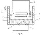
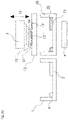
- the device located in air or another gas atmosphere has a trough 1, the trough floor of which forms a material carrier 2, which is transparent or translucent at least in a partial area 3.
- This partial area 3 of the material carrier covers at least the extent of the area that can be irradiated by the exposure unit 4 , the exposure unit 4 being arranged below the material carrier 2 .
- the exposure unit 4 has a light source (not shown) and a light modulator with which the intensity can be controlled by a control unit and adjusted in a location-selective manner in order to generate an exposure field on the material carrier 2 with the geometry desired for the layer to be formed at the moment.
- a laser can also be used in the exposure unit, the light beam of which successively scans the exposure field with the desired intensity pattern via a movable mirror that is controlled by a control unit.
- a construction platform 5 is provided above the material carrier 2 opposite the exposure unit 4 and is supported by a lifting mechanism, not shown, so that it is held in a height-adjustable manner above the material carrier 2 in the area above the exposure unit 4 .
- the construction platform 5 can also be transparent or translucent.
- a bath of highly viscous photopolymerizable material 6 is located on the material carrier 2.
- the material level 7 of the bath is defined by a suitable element, such as a squeegee, which applies the material evenly to the material carrier 2 in a specific material layer thickness a.
- the trough 1 can, for example, be assigned a guide rail on which a carriage is guided so that it can be displaced in the direction of the double arrow 8 .
- a drive ensures the back and forth movement of the carriage, which has a holder for a squeegee.
- the holder has, for example, a guide and an adjustment device in order to adjust the squeegee in the direction of the double arrow 9 in the vertical direction.
- the distance between the lower edge of the squeegee and the material carrier 2 can thus be adjusted.
- the squeegee comes to Use when the build platform moves as in 1 shown is in the raised state, and serves to distribute the material 6 evenly while setting a predetermined layer thickness.
- the layer thickness of the material 6 resulting from the material distribution process is defined by the distance between the lower edge of the squeegee and the material carrier 2 .
- the resulting material layer thickness a is greater than the component layer thickness b ( 2 ).
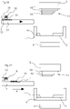
- the procedure for defining a layer of photopolymerizable material is as follows.
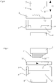
- the construction platform 5, on which component layers 10', 10" and 10"' have already been formed, is, as in 2 shown, lowered in a controlled manner by the lifting mechanism, so that the underside of the lowest component layer 10"' first touches the surface of the material 6 with height a, then dips in and approaches the material carrier 2 to such an extent that between the underside of the lowest component layer 10"' and the material carrier 2 has exactly the desired component layer thickness b.
- photopolymerizable material is displaced from the space between the underside of the bottom component layer 10"' and the material carrier 2.
- the construction platform 5 is raised again by means of the lifting mechanism, which in 3 state shown.
- the photopolymerizable material 6 is no longer present in the exposed area.
- the device therefore comprises a material removal unit 12, as shown in FIGS Figures 4 to 11 shown.
- the 4 shows the device before the formation of the device layer 10"".
- the material removal unit 12 is positioned in its starting position next to the tub 1 and is in the direction of the arrow 14 ( figure 5 ) moveable in horizontal direction.
- Adhering material 13 is now at least partially removed after the component layer 10′′′′ has been formed, in that the material removal unit 12 is initially moved between the component 11 and the tub 1 with the construction platform 5 raised.
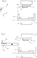
- the component layer 10"" produced last and the material removal unit 12 are then brought into contact by a relative movement in the direction of arrow 15, so that the uncured quantity of material 13 adhering to the underside and possibly to the side surface of the bottom component layer 10"" is at least partially removed is transferred to the material removal unit 12 so that the Amount of material 13' reaches the material removal unit 12, as in 6 is shown.
- the amount of material 13' is transferred to the material removal unit 12, for example, by the capillary action of an absorbent material of the material removal unit 12.
- a relative movement then takes place in order to separate the component from the material removal unit.
- a surface section of the material removal unit 12 is moved a little further in order to transport the removed amount of material away from the component layer 10"" and to provide a new surface section of the material removal unit 12 for a further material removal step, as in FIG 7 shown.
- the material removing unit 12 is returned to its original position ( 8 ), so that a further component layer 10"'" can be formed, to which in turn a quantity of material 13" adheres ( 9 ).
- the material removal unit 12 is moved between the component 11 and the tub 1 for the next material removal step and the material quantity 13'" is transferred to the material removal unit 12 as previously described ( 10 ).
- the material removing unit 12 is brought to its home position ( 11 ) and the next component layer can be created.
- the material removal unit 12 has an applicator 16 for a liquid, such as a solvent.
- a liquid such as a solvent.
- the liquid is on the applied to the surface of the material removal unit 12 so that a saturated layer 17 is formed ( 13 ).
- the adhering quantity of material 13 is subsequently at least partially transferred from the component layer with the aid of the layer 17 ( 15 ) so that the quantity of material 13 ′ reaches the material removal unit 12 .
- the material removal unit 12 or a separate unit is used to apply particles 19 to the cleaned component layer 10"" before the next component layer is produced.
- an applicator 18 is provided for this purpose, which applies particles 19 to the material removal unit 12 ( 18 ).
- the applicator 16 preferably also applies a liquid, so that a saturated layer 17 is formed.
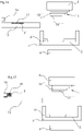
- Figures 22 to 31 show an example of a method with which a device layer can be produced from two different photopolymerizable materials.
- a modified device is used which, in comparison to the previous examples, has a second material trough 20 with a material carrier 21 in which a second material 22 is accommodated.
- a first component layer 10'" is formed by immersing the component in the one in the tub 1 Material 6 and curing of the material 6 produced ( 23 ). After lifting the component 11 ( 24 ) a quantity of material 13 again adheres to the component layer 10"" last built up, and as already described, the quantity of material 13' is transferred to the material removal unit 12 ( 25 and 26 ). In 26 it can be seen that the component layer 10"" leaves a portion 23 of the component layer 10'" uncovered. In this portion 23, a layer of the second material 22 is now produced by first removing the first trough 1 horizontally and instead placing the second trough 20 between the component 11 and the exposure unit 4 is arranged ( 27 ).
- the component 11 is immersed in the second material 22 until the previously produced component layer 10 touches the material carrier 2, so that a material layer is formed in the partial area 23, which is hardened ( 28 ). Since the adhering amount of material 13 of the first material 6 is at least partially transferred to the material removal unit 12 beforehand, so that the amount of material 13′ reaches the material removal unit 12, material 6 is prevented from mixing with the material 22 when it is immersed in the trough 20. Furthermore, it is avoided that the previously adhering amount of material 13 is also hardened by the last-mentioned formation and falsifies the geometry to be formed.
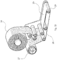
- the material removal unit 12 comprises a traveling belt 25 which is unwound from a supply roll 26 and wound onto the receiver roll 27.
- the movable belt 25 can consist of an absorbent material, in particular based on cellulose.
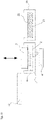
- Figure 33 shows an alternative embodiment of the material removal unit 12, with which the adhering quantity of material 13 is at least partially removed or sucked off pneumatically.
- the material removal unit 12 comprises a first channel 30 for a gas that generates a negative pressure at the mouth of the channel 32 by utilizing the Venturi effect.
- Another channel 31 opens out on the surface of the material removal unit 12 and generates a gas jet directed against the amount of material 13 adhering.
- an overpressure is also generated on the underside of the component, in that a gas pressure is generated via bores 33 (or other cavities) formed in the component 11 and the construction platform 5, which adhering amount of material 13 towards the channel 32 passes.
Abstract
Bei einem Verfahren zum schichtweisen Aufbau eines Bauteils (11) aus photopolymerisierbarem Material (6), insbesondere einem Harz mit keramischem oder metallischem Füllstoff, bei dem nacheinander Bauteilschichten (10', 10'', 10''', 10'''') übereinander ausgebildet werden, indem jeweils zwischen einer Bauplattform (5) bzw. dem Bauteil und einem Materialträger (2) eine Schicht des hochviskosen photopolymerisierbaren Materials ausgebildet wird, die ortsselektiv zur Ausbildung der gewünschten Form der Bauteilschicht ausgehärtet wird, erfolgt nach der Ausbildung einer Bauteilschicht ein Reinigungsschritt, in dem nach dem Anheben des Bauteils an der Bauteilschicht anhaftendes, nicht ausgehärtetes photopolymerisierbares Material mittels einer Reinigungseinheit (12) entfernt wird.In a method for building up a component (11) in layers from photopolymerizable material (6), in particular a resin with a ceramic or metallic filler, in which component layers (10', 10'', 10''', 10'''') are formed one on top of the other, in that a layer of the highly viscous photopolymerizable material is formed between a construction platform (5) or the component and a material carrier (2), which is cured in a location-selective manner to form the desired shape of the component layer, occurs after the formation of a component layer Cleaning step in which, after the component has been lifted, non-hardened photopolymerizable material adhering to the component layer is removed by means of a cleaning unit (12).
Description
Die Erfindung betrifft ein Verfahren zum schichtweisen Aufbau eines Bauteils aus photopolymerisierbarem Material, insbesondere einem Harz mit keramischem oder metallischem Füllstoff, bei dem nacheinander Bauteilschichten übereinander ausgebildet werden, indem jeweils auf einem Materialträger eine Materialschicht des photopolymerisierbaren Materials ausgebildet wird und die Bauplattform oder das an der Bauplattform zumindest teilweise aufgebaute Bauteil in die Materialschicht abgesenkt wird, sodass sich zwischen der Bauplattform bzw. dem Bauteil und dem Materialträger eine Schicht des photopolymerisierbaren Materials ausbildet, die insbesondere durch Bestrahlung durch den Materialträger hindurch ortsselektiv zur Ausbildung der gewünschten Geometrie der Bauteilschicht ausgehärtet wird, wonach das Bauteil mit der Bauteilschicht angehoben wird.The invention relates to a method for the layered construction of a component made of photopolymerizable material, in particular a resin with a ceramic or metallic filler, in which component layers are formed one on top of the other in that a material layer of the photopolymerizable material is formed on a material carrier and the construction platform or the The at least partially constructed component is lowered into the material layer on the construction platform, so that a layer of the photopolymerizable material is formed between the construction platform or the component and the material carrier, which is cured in a location-selective manner, in particular by irradiation through the material carrier, to form the desired geometry of the component layer, after which the component is lifted with the component layer.
Die Erfindung betrifft weiters eine Vorrichtung zur Durchführung des erfindungsgemäßen Verfahrens.The invention further relates to a device for carrying out the method according to the invention.
Ein Verfahren und eine Vorrichtung der eingangs genannten Art sind in der
Das oben beschriebene Verfahren ist insbesondere für die Verarbeitung von photopolymerisierbarem Material mit hoher Viskosität geeignet. Eine hohe Viskosität des Materials ist beispielsweise im Fall von keramikgefülltem photopolymerisierbaren Material zu beobachten. Die hohe Viskosität des photopolymerisierbaren Materials bedingt in der lithographiebasierten generativen Fertigung eine erhebliche Verschlechterung der Verarbeitbarkeit. Wenn im Rahmen der vorliegenden Erfindung von hochviskosem Material die Rede ist, so bezieht sich dies insbesondere auf eine Viskosität von mindestens 10 Pa·s.The method described above is particularly suitable for processing high-viscosity photopolymerizable material. A high viscosity of the material can be observed, for example, in the case of ceramic-filled photopolymerizable material. The high viscosity of the photopolymerizable material causes a significant deterioration in processability in lithography-based additive manufacturing. If, in the context of the present invention, high-viscosity material is mentioned, this refers in particular to a viscosity of at least 10 Pa·s.
Nach dem Aushärten einer Bauteilschicht bleibt beim Anheben des Bauteils aus dem auf dem Materialträger befindlichen Material nicht ausgehärtetes photopolymerisierbares Material an dem Bauteil haften. Das nicht ausgehärtete photopolymerisierbare Material bleibt hierbei insbesondere an der zuletzt aufgebauten Bauteilschicht haften. Dies führt dazu, dass das Bauteil am Ende des Bauprozesses von einer zähflüssigen Schicht nicht ausgehärteten photopolymerisierbaren Materials umgeben ist, die im Rahmen des Post-Processing aufwändig entfernt werden muss. Ein weiterer Nachteil des anhaftenden Materials liegt darin, dass keine Bauteile mit geschlossenen Geometrien, wie z.B. geschlossenen Hohlräumen (z.B. Kugeln), hergestellt werden können, da diese unerwünschterweise nicht ausgehärtetes photopolymerisierbares Material in den Hohlräumen enthalten würden.After a component layer has cured, uncured photopolymerizable material sticks to the component when the component is lifted from the material located on the material carrier. In this case, the uncured photopolymerizable material remains particularly attached to the component layer built up last. As a result, at the end of the construction process, the component is surrounded by a viscous layer of uncured photopolymerizable material, which has to be laboriously removed during post-processing. A further disadvantage of the adherent material is that components with closed geometries, such as closed cavities (e.g. spheres), cannot be manufactured since these would undesirably contain uncured photopolymerizable material in the cavities.
Es ist daher die Aufgabe der vorliegenden Erfindung, ein Verfahren und eine Vorrichtung der eingangs genannten Art hinsichtlich der genannten Nachteile zu verbessern.It is therefore the object of the present invention to improve a method and a device of the type mentioned at the outset with regard to the disadvantages mentioned.
Zur Lösung dieser Aufgabe sieht die Erfindung bei einem Verfahren der eingangs genannten Art im Wesentlichen vor, dass nach der Ausbildung einer Bauteilschicht ein Materialentfernungsschritt erfolgt, in dem nach dem Anheben des Bauteils an dem Bauteil, insbesondere an der Bauteilschicht, anhaftendes, nicht oder nicht vollständig ausgehärtetes photopolymerisierbares Material mittels einer Materialentfernungseinheit zumindest teilweise entfernt wird, worauf das Bauteil ggf. für den nächsten Bauschritt wieder abgesenkt wird.To solve this problem, the invention essentially provides in a method of the type mentioned at the outset that after the formation of a component layer, a material removal step takes place in which, after the component has been lifted, material adhering to the component, in particular to the component layer, is not removed or not completely removed cured photopolymerizable material is at least partially removed by means of a material removal unit, whereupon the component is lowered again, if necessary, for the next construction step.
Im Rahmen der Erfindung implizieren die Begriffe "absenken" und "anheben" nicht eine bestimmte Bewegungsrichtung, wie z.B. eine vertikale Bewegung, sondern umfassen jede Bewegung, bei der das Bauteil in Richtung zum Materialträger bewegt ("abgesenkt") und von diesem entfernt ("angehoben") wird. Beispielsweise kann das Absenken das Eintauchen des Bauteils in die Materialschicht und das Anheben des Bauteils das Austauchen der gebildeten Bauteilschicht aus dem Material umfassen.In the context of the invention, the terms "lowering" and "raising" do not imply a specific direction of movement, such as vertical movement, but include any movement in which the component is moved towards ("lowered") and away from the material carrier (" raised"). For example, lowering can include dipping the component into the material layer and raising the component can include emerging the formed component layer from the material.
Dadurch, dass anhaftendes Material nach der Ausbildung einer Bauteilschicht zumindest teilweise entfernt wird, wird der Aufwand für die Nachbearbeitung des fertig aufgebauten Bauteils reduziert.Because adhering material is at least partially removed after a component layer has been formed, the effort required for post-processing of the finished component is reduced.
Bevorzugt wird anhaftendes, nicht ausgehärtetes photopolymerisierbares Material nach der Ausbildung jeder Bauteilschicht entfernt, sodass am Ende des Bauvorgangs tatsächlich ein Bauteil erhalten wird, an dem deutlich weniger oder idealerweise keine nicht ausgehärteten Materialreste anhaften.Adhering, uncured photopolymerizable material is preferably removed after the formation of each component layer, so that at the end of the construction process a component is actually obtained to which significantly less or ideally no uncured material residues adhere.
Das Entfernen von anhaftendem Material eröffnet weiters die Möglichkeit, Bauteile mit geschlossenen Hohlräumen herzustellen, die deutlich weniger nicht ausgehärtetes Material enthalten.The removal of adhering material further opens up the possibility of manufacturing closed cavity components that contain significantly less uncured material.
Erfindungsgemäß erfolgt die Materialentfernung mit Hilfe einer Materialentfernungseinheit, bevorzugt mittels einer automatischen Materialentfernungseinheit, sodass händische Arbeitsschritte während des Bauprozesses vermieden werden können. Die Materialentfernung erfolgt hierbei in vorteilhafter Weise derart, dass die Materialentfernungseinheit nach dem Anheben des Bauteils an die Unterseite oder an den unteren Rand des Bauteils herangeführt wird und/oder umgekehrt das Bauteil an die Materialentfernungseinheit herangeführt wird, wobei das Heranführen bevorzugt automatisch erfolgt und von einer elektronischen Steuereinheit gesteuert wird.According to the invention, the material is removed with the aid of a material removal unit, preferably by means of an automatic material removal unit, so that manual work steps during the construction process can be avoided. The material is removed here in an advantageous manner such that the Material removal unit is brought after lifting the component to the underside or to the lower edge of the component and / or vice versa, the component is brought to the material removal unit, the approach is preferably carried out automatically and is controlled by an electronic control unit.
Gemäß einer bevorzugten Ausbildung der Erfindung umfasst der Materialentfernungsschritt das Inkontaktbringen des anhaftenden photopolymerisierbaren Materials mit einem Kontaktelement, vorzugsweise einem saugfähigen, insbesondere flächigen Kontaktelement. Bei dem saugfähigen Kontaktelement kann es sich beispielsweise um ein Zellstoffband, ein Papier, eine Folie, ein Vlies oder einen Schwamm handeln. Das Inkontaktbringen erfolgt auf Grund einer Relativbewegung zwischen dem Bauteil und dem saugfähigen Kontaktelement. Das saugfähige flächige Kontaktelement und die Bauteilschicht mit dem anhaftenden Material können beispielsweise in einer quer, insbesondere senkrecht, zur Ebene der Bauteilschicht verlaufenden Relativbewegung miteinander in Kontakt gebracht werden. Hierbei erfolgt die Materialentfernung nach Art eines Abtupfens der Bauteilschicht, wobei insbesondere das am Rand der Bauteilschicht anhaftende nicht ausgehärtete Material an dem saugfähigen Kontaktelement kleben bleibt. Nach dem zumindest teilweisen Entfernen des nicht ausgehärteten Materials erfolgt eine gegenseitige Beabstandung des saugfähigen Kontaktelements und des Bauteils, sodass das Bauteil für den nächsten Bauschritt wieder in das auf dem Materialträger befindliche Material abgesenkt werden kann.According to a preferred embodiment of the invention, the material removal step includes bringing the adhering photopolymerizable material into contact with a contact element, preferably an absorbent, in particular flat, contact element. The absorbent contact element can be, for example, a cellulose strip, paper, foil, fleece or sponge. The bringing into contact takes place due to a relative movement between the component and the absorbent contact element. The absorbent flat contact element and the component layer with the adhering material can be brought into contact with one another, for example, in a relative movement running transversely, in particular perpendicularly, to the plane of the component layer. In this case, the material is removed in the manner of dabbing the component layer, with the non-hardened material adhering to the edge of the component layer in particular remaining stuck to the absorbent contact element. After the at least partial removal of the uncured material, the absorbent contact element and the component are spaced apart so that the component can be lowered back into the material on the material carrier for the next construction step.
Das Kontaktelement kann alternativ eine bogenförmige, insbesondere zylindrische saugfähige Oberfläche aufweisen, sodass die Materialentfernung durch Abrollen der bogenförmigen Oberfläche auf dem Bauteil erfolgt. Das Kontaktelement kann hierbei beispielswiese als Walze ausgebildet sein. Das Kontaktelement ist zu diesem Zweck bevorzugt um eine Drehachse der bogenförmigen, insbesondere zylindrischen Oberfläche drehbar gelagert.Alternatively, the contact element can have a curved, in particular cylindrical, absorbent surface, so that the material is removed by rolling the curved surface on the component. The contact element can be designed as a roller, for example. For this purpose, the contact element is preferably mounted such that it can rotate about an axis of rotation of the arcuate, in particular cylindrical, surface.
Gemäß einer bevorzugten Verfahrensweise wird die Materialentfernungseinheit für den Materialentfernungsschritt zwischen das angehobene Bauteil und den Materialträger gebracht. Dies bedeutet, dass die Bauplattform samt dem daran ausgebildeten unfertigen Bauteil für den Materialentfernungsschritt lediglich in Höhenrichtung verlagert werden muss, wobei die laterale Ausrichtung des Bauteils zum Materialträger und der Belichtungseinheit beibehalten werden kann.According to a preferred procedure, the material removal unit for the material removal step is placed between the lifted component and the material carrier. This means that the construction platform together with the unfinished component formed on it only has to be shifted in the vertical direction for the material removal step, with the lateral alignment of the component with respect to the material carrier and the exposure unit being able to be maintained.
Alternativ kann aber vorgesehen sein, dass das Bauteil für den Materialentfernungsschritt nach dem Anheben zur Seite rotiert wird.Alternatively, however, provision can be made for the component to be rotated to the side for the material removal step after it has been lifted.
Gemäß einer vorteilhaften Weiterbildung ist das saugfähige flächige Kontaktelement als verfahrbares Band ausgebildet, wobei das Band nach einem Materialentfernungsschritt verfahren wird, um einen Bandabschnitt mit photopolymerisierbarem Material abzufördern und einen neuen Bandabschnitt für einen weiteren Materialentfernungsschritt bereitzustellen. Das verfahrbare Band kann hierbei auf einer Vorratsrolle vorrätig gehalten werden. Bevorzugt wird das Band von einer Vorratsrolle sukzessive abgerollt und das verbrauchte Band im Ausmaß der Abrollung auf eine Empfängerrolle aufgerollt. Dabei kann das Band im Bereich zwischen der Vorrats- und der Empfängerrolle mit Hilfe von Motoren, z.B. Servomotoren, gespannt gehalten wird. Im Bereich des Inkontaktkommens mit dem Bauteil kann das verfahrbare Band an der dem Bauteil abgewandten Seite von einem Stützelement abgestützt werden, um einen Gegendruck aufbringen zu können. Bevorzugt stellt das Stützelement eine elastisch nachgiebige Stützfläche zur Verfügung, sodass beim Kontakt mit dem Bauteil zwar ein Gegendruck erzeugt wird, das verfahrbare Band durch den Druck der Bauteilschicht jedoch auch nachgibt, was im Randbereich der Bauteilschicht zu einer leichten Schrägstellung des Bandes führt, was wiederum die Materialentfernung im Randbereich oder an den Seitenflächen der Bauteilschicht verbessert. Das nachgiebige Stützelement kann beispielsweise von einem Schwamm gebildet sein.According to an advantageous development, the absorbent flat contact element is designed as a movable belt, the belt being moved after a material removal step in order to remove a belt section with photopolymerizable material and to provide a new belt section for a further material removal step. The movable band can be kept in stock on a supply roll. Preferably, the tape is successively unwound from a supply roll and the used tape to the extent of unwinding on a Receiver roll rolled up. The tape can be kept taut in the area between the supply and receiver rolls with the aid of motors, eg servomotors. In the area where it comes into contact with the component, the movable belt can be supported by a support element on the side facing away from the component, in order to be able to apply a counter-pressure. The support element preferably provides an elastically resilient support surface, so that although a counter-pressure is generated when it comes into contact with the component, the moveable belt also yields due to the pressure of the component layer, which leads to a slight inclination of the belt in the edge area of the component layer, which in turn improves the material removal in the edge area or on the side surfaces of the component layer. The flexible support element can be formed by a sponge, for example.
Das verfahrbare Band kann beispielsweise von einem Papier, einer Folie, einem Gewebe, einem Filz oder einem Vlies gebildet sein.The movable belt can be formed, for example, from paper, a film, a fabric, a felt or a fleece.
Gemäß einer bevorzugten Verfahrensweise wird der Materialentfernungsschritt in wenigstens zwei Schritten durchgeführt, wobei in einem ersten Schritt eine Teilmenge des anhaftenden photopolymerisierbaren Materials entfernt wird und in einem zweiten Schritt und ggf. zumindest einem weiteren Schritt eine Restmenge des anhaftenden photopolymerisierbaren Materials entfernt wird.According to a preferred procedure, the material removal step is carried out in at least two steps, with a portion of the adhering photopolymerizable material being removed in a first step and a residual amount of the adhering photopolymerizable material being removed in a second step and optionally at least one further step.
Um die Materialentfernung zu verbessern, sieht eine bevorzugte Ausbildung vor, dass das saugfähige Kontaktelement mit einer Flüssigkeit getränkt ist oder vor dem Inkontaktbringen mit einer Flüssigkeit, bevorzugt einem Lösungsmittel, versehen wird. Das Lösungsmittel kommt in der Folge mit dem zu entfernenden Material in Kontakt und löst dieses von der Bauteilschicht.In order to improve the material removal, a preferred embodiment provides that the absorbent contact element is soaked with a liquid or before it is brought into contact with a liquid, preferably a liquid Solvent is provided. The solvent then comes into contact with the material to be removed and detaches it from the component layer.
Eine weitere bevorzugte Ausbildung sieht vor, dass nach dem Materialentfernungsschritt und vor dem nächsten Bauschritt auf die Bauteilschicht Partikel aufgebracht werden, wobei die Partikel vorzugsweise mit dem saugfähigen Kontaktelement zur Bauteilschicht transportiert und durch Inkontaktbringen des saugfähigen Kontaktelements mit der Bauteilschicht auf die Bauteilschicht aufgebracht werden. Auf diese Weise können Partikel in das Bauteil integriert werden. Die Partikel könne hierbei beliebige Formen aufweisen, wie z.B. kugelförmige, ovale oder faserförmige Partikel. Bei den eingebrachten Partikel kann es sich beispielsweise um (keramische) Kurz- oder Endlosfasern, metallische Partikel oder Porogene handeln.Another preferred embodiment provides that after the material removal step and before the next construction step, particles are applied to the component layer, the particles preferably being transported to the component layer with the absorbent contact element and being applied to the component layer by bringing the absorbent contact element into contact with the component layer. In this way, particles can be integrated into the component. The particles can have any shape, such as spherical, oval or fibrous particles. The particles introduced can be, for example, (ceramic) short or endless fibers, metallic particles or porogens.
Ein weiterer Vorteil des erfindungsgemäßen Materialentfernungsschritts liegt darin, dass die Bauteilschicht nach dem Materialentfernungsschritt einer optischen Überprüfung mittels einer Bildaufnahmeeinrichtung oder einem 3D-Scanner unterzogen werden kann. Dadurch kann während des Bauprozesses eine Überwachung des Baufortschritts vorgenommen werden, wobei insbesondere die Geometrie der zuletzt hergestellten Bauteilschicht überprüft oder das Vorhandensein von Luftblasen in der Bauteilschicht detektiert werden kann. Eine derartige Qualitätssicherung wäre ohne den erfindungsgemäßen Materialentfernungsschritt nicht möglich, weil nicht ausgehärtetes anhaftendes Material die jeweils zuletzt aufgebaute Bauteilschicht zumindest teilweise verdeckt. Ein weiterer wesentlicher Vorteil des erfindungsgemäßen Materialentfernungsschritts liegt in der Möglichkeit, ein Bauteil aus zwei oder mehreren unterschiedlichen photopolymerisierbaren Materialien aufzubauen ohne dass es zu einer signifikanten Kreuzkontamination zwischen den jeweiligen Materialvorräten auf dem Materialträger kommt.A further advantage of the material removal step according to the invention is that the component layer can be subjected to an optical check using an image recording device or a 3D scanner after the material removal step. As a result, the construction progress can be monitored during the construction process, with the geometry of the component layer produced last being checked in particular, or the presence of air bubbles in the component layer being able to be detected. Such quality assurance would not be possible without the material removal step according to the invention, because non-hardened adhering material at least partially covers the component layer that was built up last. A further significant advantage of the material removal step according to the invention lies in the possibility of constructing a component from two or more different photopolymerizable materials without there being any significant cross-contamination between the respective material stocks on the material carrier.
Das Material kann beispielsweise schichtweise gewechselt werden. Zu diesem Zweck wird bevorzugt derart vorgegangen, dass eine erste Bauteilschicht aus einem ersten photopolymerisierbaren Material gebildet wird und dass nach dem Materialentfernungsschritt zur Entfernung von an der ersten Bauteilschicht anhaftendem ersten photopolymerisierbaren Material eine zweite Bauteilschicht aus einem zweiten photopolymerisierbaren Material gebildet wird, das sich vom ersten photopolymerisierbaren Material unterscheidet.The material can be changed in layers, for example. For this purpose, the procedure is preferably such that a first component layer is formed from a first photopolymerizable material and that after the material removal step for removing first photopolymerizable material adhering to the first component layer, a second component layer is formed from a second photopolymerizable material, which differs from the first photopolymerizable material is different.
Es kann aber auch so vorgegangen werden, dass innerhalb ein und derselben Bauteilschicht zwei unterschiedliche Materialien verwendet werden. Eine bevorzugte Verfahrensweise sieht hierbei vor, dass eine Bauteilschicht mit einer ersten Geometrie aus einem ersten photopolymerisierbaren Material gebildet wird, wobei die erste Geometrie wenigstens einen Teilbereich der Unterseite der zuletzt ausgebildeten Bauteilschicht unbedeckt lässt, dass mittels des Materialentfernungsschritts an der Bauteilschicht und in dem wenigstens einen unbedeckten Teilbereich anhaftendes erstes photopolymerisierbares Material entfernt wird und dass danach ein Bauschritt mit einem zweiten photopolymerisierbaren Material vorgenommen wird, das sich vom ersten photopolymerisierbaren Material unterscheidet, wobei der Bauschritt das Aushärten von Material im Teilbereich umfasst.However, it is also possible to proceed in such a way that two different materials are used within one and the same component layer. A preferred procedure provides that a component layer with a first geometry is formed from a first photopolymerizable material, the first geometry leaving at least a partial area of the underside of the component layer formed last uncovered, that by means of the material removal step on the component layer and in the at least one uncovered portion adhering first photopolymerizable material is removed and that thereafter a construction step is carried out with a second photopolymerizable material that differs from the first photopolymerizable material differs, with the construction step comprising the curing of material in the partial area.
Für den Materialwechsel wird bevorzugt so vorgegangen, dass zwei oder mehrere Materialträger für voneinander verschiedenes photopolymerisierbares Material bereitgestellt werden, die nach dem Anheben des Bauteils selektiv zwischen der Bauplattform bzw. dem Bauteil und der Belichtungseinheit positioniert sein können.For the material change, the procedure is preferably such that two or more material carriers for different photopolymerizable material are provided, which can be positioned selectively between the construction platform or the component and the exposure unit after the component has been lifted.
Eine alternative Möglichkeit zur Materialentfernung liegt in einer fluidischen bzw. pneumatischen Materialabtragung. Eine bevorzugte Ausbildung sieht hierbei vor, dass der Materialentfernungsschritt das Erzeugen einer Fluidströmung, wie z.B. einer Flüssigkeits- oder Gasströmung, im Bereich des anhaftenden, nicht ausgehärteten photopolymerisierbaren Materials umfasst, welche das Material mitreißt.An alternative option for material removal is fluidic or pneumatic material removal. A preferred embodiment provides that the material removal step includes the generation of a fluid flow, such as a liquid or gas flow, in the area of the adhering, uncured photopolymerizable material, which entrains the material.
Alternativ kann die Materialentfernung auch durch Eintauchen des Bauteils in ein Ultraschallbad erfolgen.Alternatively, the material can also be removed by immersing the component in an ultrasonic bath.
Um die einzelnen Materialschichten für die hintereinander herzustellenden Bauteilschichten auszubilden, wird bevorzugt so vorgegangen, dass die Bauplattform nach dem Aushärtungsschritt angehoben und zur Ausbildung der nächsten Bauteilschicht wieder zum Materialträger abgesenkt wird, nachdem Material unter der angehobenen Bauplattform nachgeführt wurde, um die Materialschicht auszubilden.In order to form the individual material layers for the component layers to be produced one after the other, the procedure is preferably such that the construction platform is raised after the curing step and lowered back to the material carrier to form the next component layer, after material has been fed under the raised construction platform in order to form the material layer.
Die Nachführung des Materials wird in diesem Zusammenhang bevorzugt mittels Materialverteilung mit Hilfe einer Rakel vorgenommen, wobei die Schichtdicke der Materialschicht durch Einstellung des Abstands zwischen der Unterkante der Rakel und der materialzugewandten Oberfläche des Materialträgers eingestellt wird.In this context, the tracking of the material is preferably carried out by means of material distribution with the aid of a squeegee, the layer thickness of the material layer is adjusted by adjusting the distance between the lower edge of the squeegee and the material-facing surface of the material carrier.
Das erfindungsgemäße Verfahren eignet sich besonders für die Verarbeitung von hochviskosem, photopolymerisierbaren Material, wie z.B. eines Harzes mit keramischem oder metallischem Füllstoff. Unter einem hochviskosen Material wird hierbei ein Material verstanden, dass bei einer Temperatur von 20°C eine Viskosität von mindestens 10 Pa·s aufweist.The method according to the invention is particularly suitable for the processing of highly viscous, photopolymerizable material, such as a resin with a ceramic or metal filler. A high-viscosity material is understood to mean a material that has a viscosity of at least 10 Pa·s at a temperature of 20°C.
Gemäß einem weiteren Aspekt der Erfindung ist eine Vorrichtung zur Durchführung des erfindungsgemäßen Verfahrens vorgesehen, umfassend
- einen Materialträger für photopolymerisierbares Material, der zumindest bereichsweise lichtdurchlässig ausgebildet ist,
- eine Bauplattform, die in einstellbarer Höhe über dem Materialträger gehalten ist,
- eine Bestrahlungseinheit, die zur ortsselektiven Bestrahlung einer zwischen der Unterseite der Bauplattform und dem Materialträger ausgebildeten Materialschicht ansteuerbar ist, wodurch eine Bauteilschicht erzeugbar ist,
- eine Materialentfernungseinheit zur zumindest teilweisen Entfernung von nach dem Anheben des Bauteils an diesem, insbesondere an der Bauteilschicht, anhaftendem, nicht ausgehärteten photopolymerisierbaren Material.
- a material carrier for photopolymerizable material, which is designed to be translucent at least in some areas,
- a construction platform that is held at an adjustable height above the material carrier,
- an irradiation unit that can be controlled for the location-selective irradiation of a material layer formed between the underside of the construction platform and the material carrier, as a result of which a component layer can be produced,
- a material removal unit for the at least partial removal of non-hardened photopolymerizable material adhering to the component, in particular to the component layer, after the component has been lifted.
Bevorzugt umfasst die Vorrichtung weiters eine in einstellbarer Höhe und/oder mit einstellbarer Neigung über dem Materialträger gehaltene Rakel zum Ausbilden der Materialschicht auf dem Materialträger, wobei zur Höhenverstellung eine Stelleinheit vorgesehen ist.Preferably, the device further comprises an adjustable height and/or adjustable inclination the squeegee held on the material carrier for forming the material layer on the material carrier, an adjusting unit being provided for height adjustment.
Bevorzugt umfasst die Materialentfernungseinheit ein Kontaktelement, vorzugsweise ein saugfähiges, insbesondere flächiges Kontaktelement, welches zum Inkontaktbringen mit dem anhaftenden photopolymerisierbaren Material angeordnet ist.The material removal unit preferably comprises a contact element, preferably an absorbent, in particular flat contact element, which is arranged for bringing into contact with the adhering photopolymerizable material.
Bevorzugt ist die Materialentfernungseinheit verlagerbar angeordnet, um für den Materialentfernungsschritt zwischen das angehobene Bauteil und den Materialträger gebracht zu werden. Insbesondere ist die Materialentfernungseinheit in horizontaler Richtung, d.h. parallel zur Ebene der Bauteilschichten, verfahrbar, um zwischen das angehobene Bauteil und den Materialträger gebracht zu werden. Sobald die Materialentfernungseinheit zwischen dem angehobenen Bauteil und dem Materialträger zu liegen kommt, erfolgt im Falle einer Materialentfernungseinheit, die nach dem Prinzip der kontaktbehafteten Materialentfernung arbeitet, ein Inkontaktbringen der Materialentfernungseinheit und dem nicht ausgehärteten, an dem Bauteil anhaftenden Material. Zu diesem Zweck kann entweder das Bauteil senkrecht in Richtung zum zur Materialentfernungseinheit abwärts verfahren werden oder die Materialentfernungseinheit senkrecht in Richtung zum Bauteil aufwärts verfahren werden.Preferably, the material removing unit is displaceably arranged to be placed between the lifted component and the material carrier for the material removing step. In particular, the material removal unit is movable in a horizontal direction, i.e. parallel to the plane of the component layers, in order to be placed between the lifted component and the material carrier. As soon as the material removal unit comes to rest between the lifted component and the material carrier, in the case of a material removal unit that works according to the principle of contact-based material removal, the material removal unit and the uncured material adhering to the component are brought into contact. For this purpose, either the component can be moved vertically downwards in the direction of the material removal unit or the material removal unit can be moved vertically upwards in the direction of the component.
Gemäß einer alternativen Ausbildung ist die Bauplattform rotierbar gehalten, um das Bauteil für den Materialentfernungsschritt nach dem Anheben zur Seite zu rotieren. In diesem Fall ist die Materialentfernungseinheit seitlich der Bauplattform positioniert und es erfolgt ein Inkontaktbringen der Materialentfernungseinheit mit dem Bauteil in einer zur Seite verschwenkten Position des Bauteils.According to an alternative embodiment, the construction platform is held rotatably in order to rotate the component to the side for the material removal step after it has been lifted. In this case, the material removal unit positioned to the side of the construction platform and the material removal unit is brought into contact with the component in a position of the component pivoted to the side.
Bevorzugt ist vorgesehen, dass das saugfähige flächige Kontaktelement als verfahrbares Band ausgebildet ist. Bei dem saugfähigen Kontaktelement kann es sich beispielsweise um ein Zellstoffband, insbesondere ein fusselarmes Zellstoffband handeln.It is preferably provided that the absorbent flat contact element is designed as a movable belt. The absorbent contact element can be, for example, a cellulose tape, in particular a lint-free cellulose tape.
Gemäß einer weiteren bevorzugten Ausbildung weist die Materialentfernungseinheit einen Applikator zum Aufbringen eines Lösungsmittels oder von Partikeln auf das saugfähige Kontaktelement auf. Der Applikator kann für die Aufbringung eines Lösungsmittels einen Tropfenapplikator oder eine Sprüheinrichtung aufweisen.According to a further preferred embodiment, the material removal unit has an applicator for applying a solvent or particles to the absorbent contact element. The applicator can have a drop applicator or a spray device for applying a solvent.
Für die Ansteuerung umfasst die Vorrichtung gemäß einer bevorzugten Ausbildung
- einen elektronischen Speicher für ein virtuelles dreidimensionales Modell der Bauteilschichten und des daraus aufgebauten Bauteils,
- eine Steuereinheit, der das virtuelle Modell der Bauteilschichten zugeführt ist und die dazu ausgebildet ist, in aufeinanderfolgenden Bestrahlungsschritten übereinanderliegende Bauteilschichten auf der Bauplattform jeweils mit vorgegebener Geometrie durch Steuerung der Bestrahlungseinheit zu polymerisieren und die Materialentfernungseinheit für die Durchführung des Materialentfernungsschritts anzusteuern.
- an electronic memory for a virtual three-dimensional model of the component layers and the component constructed from them,
- a control unit, to which the virtual model of the component layers is supplied and which is designed to polymerize superimposed component layers on the construction platform in successive irradiation steps, each with a predetermined geometry, by controlling the irradiation unit and to control the material removal unit for carrying out the material removal step.
Die Erfindung wird nachfolgend anhand von in der Zeichnung schematisch dargestellten Ausführungsbeispielen näher erläutert. In dieser zeigen
-
Fig. 1 eine Schnittansicht einer Vorrichtung zum schichtweisen Aufbau eines Bauteils in aufeinanderfolgenden Phasen des Verfahrensablaufs,bis 3 -
Fig. 4 den Ablauf einer Materialentfernung gemäß der Erfindung,bis 11 -
Fig. 12 den Ablauf einer abgewandelten Ausführung der Materialentfernung gemäß der Erfindung,bis 16 -
Fig. 17 den Ablauf einer Partikelaufbringung gemäß der Erfindung,bis 21 -
Fig. 22 den Ablauf einer abgewandelten Ausführung der Materialentfernung gemäß der Erfindung,bis 31 -
Fig. 32 eine Ausführung einer bandförmigen Materialentfernungseinheit, und -
Fig. 33 eine alternative Ausführung einer Materialentfernungseinheit.
-
Figures 1 to 3 a sectional view of a device for the layered construction of a component in successive phases of the process sequence, -
Figures 4 to 11 the course of a material removal according to the invention, -
Figures 12 to 16 the sequence of a modified embodiment of the material removal according to the invention, -
Figures 17 to 21 the course of a particle application according to the invention, -
Figures 22 to 31 the sequence of a modified embodiment of the material removal according to the invention, -
32 an embodiment of a belt-shaped material removal unit, and -
Figure 33 an alternative embodiment of a material removal unit.
Ein Verfahren und eine Vorrichtung zum schichtweisen Aufbau eines Bauteils aus photopolymerisierbarem Material wird zunächst unter Bezugnahme auf die
Der Belichtungseinheit 4 gegenüber ist über dem Materialträger 2 eine Bauplattform 5 vorgesehen, die von einem nicht dargestellten Hubmechanismus getragen wird, so dass sie in höhenverstellbarer Weise über dem Materialträger 2 im Bereich über der Belichtungseinheit 4 gehalten wird. Die Bauplattform 5 kann ebenfalls durchsichtig oder durchscheinend sein.A
Auf dem Materialträger 2 befindet sich ein Bad aus hochviskosem photopolymerisierbaren Material 6. Der Materialspiegel 7 des Bades wird durch ein geeignetes Element definiert, wie z.B. eine Rakel, welche das Material in einer bestimmten Materialschichtdicke a gleichmäßig auf den Materialträger 2 aufträgt. Der Wanne 1 kann beispielsweise eine Führungsschiene zugeordnet sein, auf der ein Schlitten in Richtung des Doppelpfeils 8 verschieblich geführt ist. Ein Antrieb sorgt für die Hin-und Herbewegung des Schlittens, der eine Halterung für eine Rakel aufweist. Die Halterung weist beispielsweise eine Führung und eine Verstelleinrichtung auf, um die Rakel in Richtung des Doppelpfeils 9 in Höhenrichtung zu verstellen. Damit kann der Abstand der Unterkante der Rakel vom Materialträger 2 eingestellt werden. Die Rakel kommt zum Einsatz, wenn sich die Bauplattform wie in
Die so entstandene Materialschichtdicke a ist dabei größer als die Bauteilschichtdicke b (
Diese Schritte werden nachfolgend mehrfach wiederholt, um weitere Bauteilschichten aus photopolymerisierbarem Material zu erhalten. Das im belichteten Bereich nicht mehr vorhandene Material wird durch die Wiederherstellung des Materialspiegels 7 bzw. der Materialschichtdicke a ersetzt. Der Abstand der Unterseite der zuletzt gebildeten Bauteilschicht 10"" zum Materialträger 2 wird auf die gewünschte Bauteilschichtdicke b eingestellt und daraufhin das photopolymerisierbare Material in der gewünschten Weise ortsselektiv ausgehärtet.These steps are subsequently repeated several times in order to obtain further component layers made of photopolymerizable material. The material that is no longer present in the exposed area is replaced by restoring the
Beim Anheben der Bauplattform bleibt eine Menge 13 eines nicht ausgehärteten photopolymerisierbaren Materials 6 an dem Bauteil, insbesondere an der zuletzt aufgebauten Bauteilschicht 10"", haften. Erfindungsgemäß umfasst die Vorrichtung daher eine Materialentfernungseinheit 12, wie in den
Nach diesem Materialentfernungsschritt wird ein Oberflächenabschnitt der Materialentfernungseinheit 12 ein Stück weiterverfahren, um die entfernte Materialmenge von der Bauteilschicht 10"" wegzubefördern und einen neuen Oberflächenabschnitt der Materialentfernungseinheit 12 für einen weiteren Materialentfernungsschritt bereitzustellen, wie in
Bei der abgewandelten Vorgehensweise gemäß den
Bei der Ausbildung gemäß
Zuerst wird eine erste Bauteilschicht 10'" durch Eintauchen des Bauteils in das in der Wanne 1 befindliche Material 6 und Aushärten des Materials 6 erzeugt (
In
Claims (18)
Priority Applications (2)
| Application Number | Priority Date | Filing Date | Title |
|---|---|---|---|
| EP20020586.2A EP4008523B1 (en) | 2020-12-03 | 2020-12-03 | Method and device for layered construction of a component made from photopolymerisable material |
| US17/538,772 US20220176626A1 (en) | 2020-12-03 | 2021-11-30 | Method and device for building up a component in layers from photopolymerizable material |
Applications Claiming Priority (1)
| Application Number | Priority Date | Filing Date | Title |
|---|---|---|---|
| EP20020586.2A EP4008523B1 (en) | 2020-12-03 | 2020-12-03 | Method and device for layered construction of a component made from photopolymerisable material |
Publications (3)
| Publication Number | Publication Date |
|---|---|
| EP4008523A1 true EP4008523A1 (en) | 2022-06-08 |
| EP4008523B1 EP4008523B1 (en) | 2023-11-29 |
| EP4008523C0 EP4008523C0 (en) | 2023-11-29 |
Family
ID=73726532
Family Applications (1)
| Application Number | Title | Priority Date | Filing Date |
|---|---|---|---|
| EP20020586.2A Active EP4008523B1 (en) | 2020-12-03 | 2020-12-03 | Method and device for layered construction of a component made from photopolymerisable material |
Country Status (2)
| Country | Link |
|---|---|
| US (1) | US20220176626A1 (en) |
| EP (1) | EP4008523B1 (en) |
Families Citing this family (1)
| Publication number | Priority date | Publication date | Assignee | Title |
|---|---|---|---|---|
| US20240033993A1 (en) * | 2022-07-28 | 2024-02-01 | General Electric Company | Systems and methods for additive manufacturing |
Citations (8)
| Publication number | Priority date | Publication date | Assignee | Title |
|---|---|---|---|---|
| WO2010045950A1 (en) | 2008-10-20 | 2010-04-29 | Ivoclar Vivadent Ag | Device and method for processing light-polymerizable material for the layered assembly of molds |
| EP2505341A1 (en) | 2011-03-29 | 2012-10-03 | Ivoclar Vivadent AG | Method for layered construction of a moulded part from highly viscous photopolymerisable material |
| US20150165695A1 (en) * | 2013-12-13 | 2015-06-18 | Xyzprinting, Inc. | Three dimensional printing apparatus |
| US20170072635A1 (en) * | 2011-01-31 | 2017-03-16 | Global Filtration Systems, A Dba Of Gulf Filtration Systems Inc. | Method and apparatus for making three-dimensional objects from multiple solidifiable materials |
| US20170182708A1 (en) * | 2015-12-09 | 2017-06-29 | Autodesk, Inc. | Multi-material stereolithographic three dimensional printing |
| WO2019190902A1 (en) * | 2018-03-27 | 2019-10-03 | Carbon, Inc. | Functional surface coating methods foradditively manufactured products |
| EP3621186A1 (en) * | 2018-09-05 | 2020-03-11 | VAF GmbH | Cleaning device and method for cleaning a dipped coated body |
| WO2020138617A1 (en) | 2018-12-27 | 2020-07-02 | 한국기계연구원 | Apparatus for washing 3d printing structure and method for washing 3d printing structure using same |
Family Cites Families (1)
| Publication number | Priority date | Publication date | Assignee | Title |
|---|---|---|---|---|
| EP3969245A4 (en) * | 2019-05-17 | 2023-01-25 | Holo, Inc. | Stereolithography three-dimensional printing systems and methods |
-
2020
- 2020-12-03 EP EP20020586.2A patent/EP4008523B1/en active Active
-
2021
- 2021-11-30 US US17/538,772 patent/US20220176626A1/en active Pending
Patent Citations (9)
| Publication number | Priority date | Publication date | Assignee | Title |
|---|---|---|---|---|
| WO2010045950A1 (en) | 2008-10-20 | 2010-04-29 | Ivoclar Vivadent Ag | Device and method for processing light-polymerizable material for the layered assembly of molds |
| US20170072635A1 (en) * | 2011-01-31 | 2017-03-16 | Global Filtration Systems, A Dba Of Gulf Filtration Systems Inc. | Method and apparatus for making three-dimensional objects from multiple solidifiable materials |
| EP2505341A1 (en) | 2011-03-29 | 2012-10-03 | Ivoclar Vivadent AG | Method for layered construction of a moulded part from highly viscous photopolymerisable material |
| US20150165695A1 (en) * | 2013-12-13 | 2015-06-18 | Xyzprinting, Inc. | Three dimensional printing apparatus |
| US20170182708A1 (en) * | 2015-12-09 | 2017-06-29 | Autodesk, Inc. | Multi-material stereolithographic three dimensional printing |
| WO2019190902A1 (en) * | 2018-03-27 | 2019-10-03 | Carbon, Inc. | Functional surface coating methods foradditively manufactured products |
| EP3621186A1 (en) * | 2018-09-05 | 2020-03-11 | VAF GmbH | Cleaning device and method for cleaning a dipped coated body |
| WO2020138617A1 (en) | 2018-12-27 | 2020-07-02 | 한국기계연구원 | Apparatus for washing 3d printing structure and method for washing 3d printing structure using same |
| US20210101342A1 (en) | 2018-12-27 | 2021-04-08 | Korea Institute Of Machinery & Materials | Cleaning apparatus for 3d printing structure and cleaning method for 3d printing structure using the same |
Also Published As
| Publication number | Publication date |
|---|---|
| EP4008523B1 (en) | 2023-11-29 |
| US20220176626A1 (en) | 2022-06-09 |
| EP4008523C0 (en) | 2023-11-29 |
Similar Documents
| Publication | Publication Date | Title |
|---|---|---|
| EP2855119B1 (en) | Method for creating an 3d object | |
| EP2864108B1 (en) | Device and method for layer-by-layer production of a three-dimensional object | |
| EP3277481B1 (en) | Method and device for the layered construction of a shaped part | |
| DE19957370C2 (en) | Method and device for coating a substrate | |
| DE19853978C1 (en) | Apparatus for selective laser smelting comprises a roller that moves over the processing surface using an element to distribute powder | |
| EP3277482A1 (en) | Method and device for the layered construction of a shaped part | |
| DE102012021284B4 (en) | Apparatus and method for the layered production of components by means of photopolymerization | |
| DE3511124C2 (en) | ||
| DE3929820C1 (en) | ||
| EP0897796A1 (en) | Method of manufacturing a screen printing jig and apparatus therefor | |
| DE19633407A1 (en) | Device and method for applying photoresist to non-flat base body surfaces for photolithographic processes | |
| DE3012988A1 (en) | DEVICE AND METHOD FOR PRODUCING A PRINT PLATE SHEET | |
| EP4008523B1 (en) | Method and device for layered construction of a component made from photopolymerisable material | |
| EP3580617B1 (en) | Method and device for producing a three-dimensional shaped object by means of layer-by-layer material application | |
| DE19612749A1 (en) | Device for painting outer circumference of columns | |
| DE2607695B2 (en) | PROCESS FOR EMBOSSING A DECORATIVE MATERIAL TRACK AND DECORATIVE TRACK MATERIAL | |
| WO1996014203A1 (en) | Process and device for producing a three-dimensional object | |
| DE10159084A1 (en) | Printing profile used for relief and intaglio printing comprises a flat support with a structured surface having several elevations in several overlapping layers on the support | |
| DE102009024334B4 (en) | Device and method for feeding a layer of material onto a construction platform or at least one material layer located on the construction platform for producing an object by means of a generative manufacturing method | |
| EP4188680A1 (en) | Method for producing a 3d shaped article, and device using a sieve plate | |
| WO2017032760A1 (en) | Method and device for the application of a structure onto a rigid substrate | |
| WO1995009078A1 (en) | Method and device for producing a three-dimensional object | |
| EP0383251A2 (en) | Method and device for evening rough, structured or heterogeneous surfaces | |
| DE102017205903A1 (en) | Method and device for producing a component by means of multi-material printing in the powder bed process | |
| WO2021151777A1 (en) | 3d printer for the additive manufacture of a component, and printing method |
Legal Events
| Date | Code | Title | Description |
|---|---|---|---|
| PUAI | Public reference made under article 153(3) epc to a published international application that has entered the european phase |
Free format text: ORIGINAL CODE: 0009012 |
|
| STAA | Information on the status of an ep patent application or granted ep patent |
Free format text: STATUS: THE APPLICATION HAS BEEN PUBLISHED |
|
| AK | Designated contracting states |
Kind code of ref document: A1 Designated state(s): AL AT BE BG CH CY CZ DE DK EE ES FI FR GB GR HR HU IE IS IT LI LT LU LV MC MK MT NL NO PL PT RO RS SE SI SK SM TR |
|
| STAA | Information on the status of an ep patent application or granted ep patent |
Free format text: STATUS: REQUEST FOR EXAMINATION WAS MADE |
|
| 17P | Request for examination filed |
Effective date: 20221201 |
|
| RBV | Designated contracting states (corrected) |
Designated state(s): AL AT BE BG CH CY CZ DE DK EE ES FI FR GB GR HR HU IE IS IT LI LT LU LV MC MK MT NL NO PL PT RO RS SE SI SK SM TR |
|
| TPAC | Observations filed by third parties |
Free format text: ORIGINAL CODE: EPIDOSNTIPA |
|
| RIC1 | Information provided on ipc code assigned before grant |
Ipc: B22F 7/08 20060101ALI20230608BHEP Ipc: B29C 64/194 20170101ALI20230608BHEP Ipc: B29C 64/236 20170101ALI20230608BHEP Ipc: B29C 64/241 20170101ALI20230608BHEP Ipc: B29C 64/321 20170101ALI20230608BHEP Ipc: B29C 64/35 20170101ALI20230608BHEP Ipc: B33Y 10/00 20150101ALI20230608BHEP Ipc: B33Y 30/00 20150101ALI20230608BHEP Ipc: B33Y 40/00 20200101ALI20230608BHEP Ipc: B22F 10/00 20210101ALI20230608BHEP Ipc: B22F 12/00 20210101ALI20230608BHEP Ipc: B33Y 70/10 20200101ALI20230608BHEP Ipc: B08B 1/00 20060101ALI20230608BHEP Ipc: B29C 64/124 20170101AFI20230608BHEP |
|
| GRAP | Despatch of communication of intention to grant a patent |
Free format text: ORIGINAL CODE: EPIDOSNIGR1 |
|
| STAA | Information on the status of an ep patent application or granted ep patent |
Free format text: STATUS: GRANT OF PATENT IS INTENDED |
|
| INTG | Intention to grant announced |
Effective date: 20230717 |
|
| GRAS | Grant fee paid |
Free format text: ORIGINAL CODE: EPIDOSNIGR3 |
|
| GRAA | (expected) grant |
Free format text: ORIGINAL CODE: 0009210 |
|
| STAA | Information on the status of an ep patent application or granted ep patent |
Free format text: STATUS: THE PATENT HAS BEEN GRANTED |
|
| AK | Designated contracting states |
Kind code of ref document: B1 Designated state(s): AL AT BE BG CH CY CZ DE DK EE ES FI FR GB GR HR HU IE IS IT LI LT LU LV MC MK MT NL NO PL PT RO RS SE SI SK SM TR |
|
| REG | Reference to a national code |
Ref country code: GB Ref legal event code: FG4D Free format text: NOT ENGLISH |
|
| REG | Reference to a national code |
Ref country code: CH Ref legal event code: EP |
|
| REG | Reference to a national code |
Ref country code: DE Ref legal event code: R096 Ref document number: 502020006164 Country of ref document: DE |
|
| REG | Reference to a national code |
Ref country code: IE Ref legal event code: FG4D Free format text: LANGUAGE OF EP DOCUMENT: GERMAN |
|
| U01 | Request for unitary effect filed |
Effective date: 20231206 |
|
| U07 | Unitary effect registered |
Designated state(s): AT BE BG DE DK EE FI FR IT LT LU LV MT NL PT SE SI Effective date: 20231212 |
|
| U20 | Renewal fee paid [unitary effect] |
Year of fee payment: 4 Effective date: 20231207 |
|
| PG25 | Lapsed in a contracting state [announced via postgrant information from national office to epo] |
Ref country code: GR Free format text: LAPSE BECAUSE OF FAILURE TO SUBMIT A TRANSLATION OF THE DESCRIPTION OR TO PAY THE FEE WITHIN THE PRESCRIBED TIME-LIMIT Effective date: 20240301 |
|
| PG25 | Lapsed in a contracting state [announced via postgrant information from national office to epo] |
Ref country code: IS Free format text: LAPSE BECAUSE OF FAILURE TO SUBMIT A TRANSLATION OF THE DESCRIPTION OR TO PAY THE FEE WITHIN THE PRESCRIBED TIME-LIMIT Effective date: 20240329 |