EP4007902B1 - Drehbetonvolumenbestimmung - Google Patents
Drehbetonvolumenbestimmung Download PDFInfo
- Publication number
- EP4007902B1 EP4007902B1 EP20847825.5A EP20847825A EP4007902B1 EP 4007902 B1 EP4007902 B1 EP 4007902B1 EP 20847825 A EP20847825 A EP 20847825A EP 4007902 B1 EP4007902 B1 EP 4007902B1
- Authority
- EP
- European Patent Office
- Prior art keywords
- concrete
- drum
- mixer drum
- probe
- slump
- Prior art date
- Legal status (The legal status is an assumption and is not a legal conclusion. Google has not performed a legal analysis and makes no representation as to the accuracy of the status listed.)
- Active
Links
Images


Classifications
-
- B—PERFORMING OPERATIONS; TRANSPORTING
- B28—WORKING CEMENT, CLAY, OR STONE
- B28C—PREPARING CLAY; PRODUCING MIXTURES CONTAINING CLAY OR CEMENTITIOUS MATERIAL, e.g. PLASTER
- B28C5/00—Apparatus or methods for producing mixtures of cement with other substances, e.g. slurries, mortars, porous or fibrous compositions
- B28C5/42—Apparatus specially adapted for being mounted on vehicles with provision for mixing during transport
- B28C5/4203—Details; Accessories
- B28C5/4206—Control apparatus; Drive systems, e.g. coupled to the vehicle drive-system
- B28C5/422—Controlling or measuring devices
-
- B—PERFORMING OPERATIONS; TRANSPORTING
- B28—WORKING CEMENT, CLAY, OR STONE
- B28C—PREPARING CLAY; PRODUCING MIXTURES CONTAINING CLAY OR CEMENTITIOUS MATERIAL, e.g. PLASTER
- B28C5/00—Apparatus or methods for producing mixtures of cement with other substances, e.g. slurries, mortars, porous or fibrous compositions
- B28C5/42—Apparatus specially adapted for being mounted on vehicles with provision for mixing during transport
- B28C5/4203—Details; Accessories
- B28C5/4231—Proportioning or supplying water
-
- B—PERFORMING OPERATIONS; TRANSPORTING
- B28—WORKING CEMENT, CLAY, OR STONE
- B28C—PREPARING CLAY; PRODUCING MIXTURES CONTAINING CLAY OR CEMENTITIOUS MATERIAL, e.g. PLASTER
- B28C5/00—Apparatus or methods for producing mixtures of cement with other substances, e.g. slurries, mortars, porous or fibrous compositions
- B28C5/42—Apparatus specially adapted for being mounted on vehicles with provision for mixing during transport
- B28C5/4203—Details; Accessories
- B28C5/4234—Charge or discharge systems therefor
- B28C5/4237—Charging, e.g. hoppers
-
- B—PERFORMING OPERATIONS; TRANSPORTING
- B28—WORKING CEMENT, CLAY, OR STONE
- B28C—PREPARING CLAY; PRODUCING MIXTURES CONTAINING CLAY OR CEMENTITIOUS MATERIAL, e.g. PLASTER
- B28C5/00—Apparatus or methods for producing mixtures of cement with other substances, e.g. slurries, mortars, porous or fibrous compositions
- B28C5/42—Apparatus specially adapted for being mounted on vehicles with provision for mixing during transport
- B28C5/4272—Apparatus specially adapted for being mounted on vehicles with provision for mixing during transport with rotating drum rotating about a horizontal or inclined axis, e.g. comprising tilting or raising means for the drum
-
- B—PERFORMING OPERATIONS; TRANSPORTING
- B28—WORKING CEMENT, CLAY, OR STONE
- B28C—PREPARING CLAY; PRODUCING MIXTURES CONTAINING CLAY OR CEMENTITIOUS MATERIAL, e.g. PLASTER
- B28C7/00—Controlling the operation of apparatus for producing mixtures of clay or cement with other substances; Supplying or proportioning the ingredients for mixing clay or cement with other substances; Discharging the mixture
- B28C7/02—Controlling the operation of the mixing
- B28C7/022—Controlling the operation of the mixing by measuring the consistency or composition of the mixture, e.g. with supply of a missing component
- B28C7/024—Controlling the operation of the mixing by measuring the consistency or composition of the mixture, e.g. with supply of a missing component by measuring properties of the mixture, e.g. moisture, electrical resistivity, density
-
- B—PERFORMING OPERATIONS; TRANSPORTING
- B28—WORKING CEMENT, CLAY, OR STONE
- B28C—PREPARING CLAY; PRODUCING MIXTURES CONTAINING CLAY OR CEMENTITIOUS MATERIAL, e.g. PLASTER
- B28C7/00—Controlling the operation of apparatus for producing mixtures of clay or cement with other substances; Supplying or proportioning the ingredients for mixing clay or cement with other substances; Discharging the mixture
- B28C7/02—Controlling the operation of the mixing
- B28C7/022—Controlling the operation of the mixing by measuring the consistency or composition of the mixture, e.g. with supply of a missing component
- B28C7/026—Controlling the operation of the mixing by measuring the consistency or composition of the mixture, e.g. with supply of a missing component by measuring data of the driving system, e.g. rotational speed, torque, consumed power
-
- G—PHYSICS
- G01—MEASURING; TESTING
- G01N—INVESTIGATING OR ANALYSING MATERIALS BY DETERMINING THEIR CHEMICAL OR PHYSICAL PROPERTIES
- G01N11/00—Investigating flow properties of materials, e.g. viscosity, plasticity; Analysing materials by determining flow properties
- G01N11/10—Investigating flow properties of materials, e.g. viscosity, plasticity; Analysing materials by determining flow properties by moving a body within the material
- G01N11/14—Investigating flow properties of materials, e.g. viscosity, plasticity; Analysing materials by determining flow properties by moving a body within the material by using rotary bodies, e.g. vane
-
- G—PHYSICS
- G01—MEASURING; TESTING
- G01N—INVESTIGATING OR ANALYSING MATERIALS BY DETERMINING THEIR CHEMICAL OR PHYSICAL PROPERTIES
- G01N11/00—Investigating flow properties of materials, e.g. viscosity, plasticity; Analysing materials by determining flow properties
- G01N2011/0046—In situ measurement during mixing process
Definitions
- the invention relates to the field of concrete rheological measurement, and more particularly to a method and a system that considers the effect of non-Newtonian fluid surface flow anomalies, such as convexity, concavity, and/or cascading, when determining volume of concrete using an entry/exit probe inside a rotating mixer drum.
- non-Newtonian fluid surface flow anomalies such as convexity, concavity, and/or cascading
- Biesak et al. disclosed a system for sensing volume and/or viscosity of a concrete slurry contained in a rotating drum.
- the sensor was mounted on an inner drum wall, and could contain an acoustic transducer, accelerometer, and pressure sensor to enable a signal processor to determine angular positions and entry and exit points relative to the concrete load. It was pointed out that while low viscosity concrete slurries remain level within the drum, high viscosity concrete slurries can "ride up the wall” such that there is a "tilt" in the level of the concrete (when the drum is viewed in cross-section perspective). The amount of tilt was said to depend upon the viscosity of the concrete and the speed of rotation of the drum (See e.g., page 11 at lines 19-24; Fig. 5 ).
- the present inventors realize that viscous concrete mixes at elevated drum rotation speeds can manifest surface flow phenomena that can deceive system processors used for calculating volume and/or viscosity of concrete loads based on rotational entry and exit points of a sensor probe mounted inside the rotating concrete mixer drum.
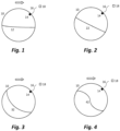
- Figs. 1 and 2 are cross-section view of a concrete mixer drum 10 along its rotational axis wherein a sensor probe 14, shown in communication 16 with a processor 18, rotates into and out of the concrete load (shown at 12 and 22, respectively).
- a "low viscosity" concrete 12 is shown in Fig. 1 ; while a “high viscosity” concrete 22 is shown in Fig. 2 .
- the surface flow of the load of concrete 22 having higher viscosity ( Fig. 2 ) displays an angular orientation as compared to low viscosity concrete 12 ( Fig. 1 ) due to a "riding up a wall effect" as shown in Fig. 2 .
- Fig. 3 an exemplary phenomenon is illustrated wherein the entry/exit points for a probe 14 mounted inside the rotating mixer drum 10 could be similar to those for Fig. 2 , except that the flowing surface of the concrete 32 is concave when viewed along the cross-sectional perspective of the mixer drum 10.
- This concavity is due to higher viscosity of the concrete which is "riding up” the drum wall (in the direction of rotation), as well as due to particle interaction of the aggregates (e.g., sand, stones) within the concrete mix 32.
- the degree of concavity or departure from curvature as compared to level concrete is likely to be different at various drum speeds.
- a system processor used for calculating volume of the concrete based on signals received from the probe upon rotational entry and exit points can be fooled into "thinking" that the volume of concrete 32 illustrated in Fig. 3 is identical to the volume of concrete 22 illustrated in Fig. 2 .
- the present inventors note here that the flow surface may also display convexity in some situations which could also affect volume calculations based on in-and-out sensor points.
- cascading effects demonstrates that at some point the concrete begins to manifest flow behaviors which are a combination of non-Newtonian fluids and granular material; the behavior of the surface flow becomes affected by the movement of granular particles within the slurry.
- the present inventors believe that such complex behaviors need to be taken into account during volume calculations based on probe entry/exit points. While mild cascading effects might not hinder accurate concrete load volume calculation where the concrete delivery truck driver maintains a low mixer drum speed (e.g., 1 RPM), problems arise when pressures of the construction site induce the driver to rush when mixing and pouring the concrete.
- truck driver to rotate the mixer drum at a faster speed: for example, a requirement to rotate the drum a minimum number of times before the load can be poured; a desire to mix in water and/or chemical admixture so that the concrete load can be poured; a need to have the concrete poured sooner so that construction workers are not waiting around the construction site to finish (smoothen) the placed concrete; a desire to return to the batch plant sooner for the next delivery for the end of the work shift, etc.
- Fig. 4 is an illustration of a concrete load 42 being subjected to a mixer drum 10 rotation speed where cascading effects, in the surface flow of the concrete 10 when viewed in cross-section perspective, can increasingly hinder accurate determination of concrete load volume.
- extreme "S" curve shapes in the concrete 42 can become highly asymmetrical in nature: wherein the center of the "S" shape could shift with respect to the entry and exit points of the probe; or wherein the entry and exit points of the probe could be unevenly changed with respect to entry and exit points at a lower drum speed.
- in-and-out data generated by the probe can be compared with in-and-out probe data previously obtained from concrete loads having the same rheology.
- in-and-out signal data for a current concrete load can be compared to historical data, and two or more factors can be considered, and used for calculation of current load volume and/or to adjust (calibrate or recalibrate) the process factors by which the volume value is obtained.
- the present invention thus provides a method and system for determining and/or calibrating concrete load volume calculations based on use of in-and-out sensor probe in rotating concrete mixer drums. For example, current in-and-out data and slump values can be compared, using a processor, with stored in-and-out data and slump values to provide an associated volume value for the concrete before any portion of the load is discharged (e.g., such as the original load volume value contained on a batch ticket).
- the method for determining volume of concrete comprises: (A) rotating a concrete load contained within a mixer drum having an inner wall, a non-vertical axis of rotation, and at least one sensor probe mounted on or along the inner wall and configured to transmit in-and-out signal data when rotated through the concrete load, using (i) probe submergence and non-submergence intervals or (ii) probe entry angle and exit angles, to a processor configured to receive the in-and-out signal data and to calculate a value corresponding to volume of the concrete load; (B) the processor performing the volume value calculation by accessing a database having stored values of concrete load volumes as correlated with in-and-out signal data previously obtained from sensor probes (e.g., preferably at various drum rotation speeds); and (C) performing, based on the volume value calculation, at least one function chosen from (i) administering a dosage of water or admixture into the concrete load, (ii) expelling a volume of concrete from the mixer drum, (iii) providing
- the processor preferably takes into account other factors in addition to at least one of rheology (e.g., slump, slump flow), and angle of tilt of concrete load (as may be experienced when the delivery truck is driving up or down a sloped road surface).
- the other factors may include concrete mix design (e.g., cement content), mixer drum design, or any combination of the foregoing, in addition to different rotation speeds of the mixer drum.
- the system of the present invention comprises: a processor and at least one sensor probe in communication with the processor, wherein the processor is programmed to perform the foregoing method of the present invention; wherein the system further comprises a mixer drum having an inner wall and a non-vertical axis of rotation; wherein the at least one sensor probe is mounted on or along the inner wall and is configured to transmit in-and-out signal data when rotated through a concrete load contained within the mixer drum.
- concrete as used herein may be understood to include ready-mix concrete.
- concrete includes hydratable cement or cementitious binder (e.g., an ordinary Portland cement, optionally with supplemental cementitious materials, such as granulated blast furnace slag, fly ash, limestone, and/or natural pozzolan) in combination with aggregates (e.g., sand, stone), water (in amounts sufficient to create a flowable or pumpable slurry), and one or more optional chemical admixtures (e.g., cement dispersants such as water-reducers called plasticizers or superplasticizers, set accelerators, set retarders, corrosion inhibitors (for metal rebar use), strength enhancers, and the like).
- cement dispersants such as water-reducers called plasticizers or superplasticizers, set accelerators, set retarders, corrosion inhibitors (for metal rebar use), strength enhancers, and the like.
- mixer drum can cover fixed or mobile batch mixers within concrete batch plants, or, more preferably, the rotatable mixer drums having non-vertical axis of rotation, such as found on ready-mix concrete delivery trucks.
- Examples of concrete mixer drums (e.g., on ready-mix trucks) having axial rotation at (a non-vertical) angle, are illustrated in US Patent 10,183,418 ofJorden et al. (See e.g., Fig. 1 ) and US Patent 10,041,928 of Berman (See also Fig. 1 ), owned by the common assignee hereof.
- Such mixer drums typically have at least one blade or fin mounted on the inner wall of the drum and arranged spirally around the axis of rotation, such that rotation of the drum in one direction forces concrete components towards a closed end of the drum (mixing or loading mode), while rotation in the opposite direction expels materials through the open end of the drum (pouring mode).
- Exemplary sensor probes contemplated for use in the invention may include force type probes (e.g., stress or strain gauges, load cells), acoustic transducer type probes, or other electro-mechanical types which are mounted within the cavity of the drum.
- the sensor probe is mounted on an inner wall of the drum, and, more preferably, it is mounted on a removable hatch lid or door in the inner drum wall.
- US Patent 10,041,928 of Berman illustrates a force type sensor probe, powered by solar panel means, attached to a hatch door which is accessible from the outside of the mixer (See e.g., Fig. 1 ).
- Suitable sensors require the ability to distinguish between states of submergence or unsubmerged with respect to concrete, and more preferably with respect to water or slurry -- such as "grey water” at the bottom of the mixer drum.
- "Grey water” is the term sometimes used to refer to remaining or returned concrete slurry, which may or may not be diluted with water and/or a retarding agent.
- grey water is the term sometimes used to refer to remaining or returned concrete slurry, which may or may not be diluted with water and/or a retarding agent.
- a binary signal is suitable to determine contact with water, slurry, or other material at the bottom of the mixer drum.
- sensors based on electrical resistivity will show a marked decrease in resistivity, because grey water is a conductive medium.
- the submersion fraction or inverse fraction can be calculated in several ways. It is conceivable that multiple sensors can be used to enhance the accuracy of the measurement or to provide redundancy if a single sensor malfunctions. If a redundant sensor fails, the system may detect the malfunction and switch to the alternative sensor and may also alert to the malfunction. These sensors may be attached, for example, on a hatch.
- the invention provides a method for calibrating volume of concrete, which comprises: (A) rotating a concrete load contained within a mixer drum having an inner wall, a non-vertical axis of rotation, and at least one sensor probe mounted on or along the inner wall and configured to transmit in-and-out signal data when rotated through the concrete load, using (i) probe submergence and non-submergence intervals or (ii) probe entry angle and exit angles, to a processor configured to receive the in-and-out signal data and to calculate a value corresponding to volume of the concrete load; (B) the processor performing the volume value calculation by accessing a database having stored values of concrete load volumes as correlated with in-and-out signal data previously obtained from sensor probes (preferably at various drum rotation speeds); and (C) performing, based on the volume value calculation, at least one function chosen from (i) administering a dosage of water or admixture into the concrete load, (ii) expelling a volume of concrete from the mixer drum, (ii
- the sensor probe is a contact or pressure type switch, which can sense electrical (conductive) or pressure of the concrete.
- a contact switch which closes (turns "on") an electrical circuit when submerged in the concrete load and opens a circuit (turns "off” or disconnects) an electrical circuit when non-submerged in the concrete load, an acoustic transducer, or a combination thereof.
- the contact or pressure-type switch is effective for measuring the presence of water or diluted slurry at the bottom of the mixer drum, such that this type of sensor probe can be used for measuring "grey water” which is remaining or returned concrete.
- the sensor probe may be a force type, having sensors that are based on the use of strain or stress gauge(s) or load cell(s) for measuring forces on the probe is rotated through the concrete load.
- force type probes can additionally be used for monitoring slump of the concrete load.
- the sensor probe could be an acoustic transducer which generated signals that reflected or indicated state of submergence within or emergence from the concrete (See e.g., WO 2019/040562 A1 of Biesak et al. ).
- the invention provides a method wherein, in step (A), the calculation of a value for the volume of the concrete load contained in the mixer drum comprises adjustment of a concrete load volume value as included in or on a batch ticket issued by a batch plant.
- the adjusted volume may then, for example, be printed on a delivery ticket after the concrete is poured at a building site.
- the concrete load volume value is adjusted, as a result of, or as part of, the operation of calculating the current concrete load volume value.
- a value corresponding to the delivered concrete e.g., the volume expelled from the drum at the building site
- the rheology property being monitored can include slump, slump flow, yield stress, or other rheology property as taught in the patent literature, as mentioned herein.
- the tilt angle of the drum can be monitored using one or more accelerometers, such as one mounted on the rotating drum (e.g., housed next to or as part of the sensor probe), and such as one mounted on a concrete delivery truck frame, or both on the drum and truck frame.
- an accelerometer could be installed with or as part of the sensor probe on a mixer drum hatch.
- the invention provides a method wherein the rotatable concrete mixer drum is mounted on a ready-mix concrete delivery truck.
- preferred truck-mounted mixer drums have a load capacity of at least 6 cubic meters (8 cubic yards) of concrete, and at least two blades spirally arranged about the axis of rotation; and the axis of drum rotation is preferably between 5 to 75 degrees with respect to horizontal, and more preferably the axis of drum rotation is 10 to 55 degrees with respect to horizontal.
- a sensor probe having a stress gauge can be used to monitor the slump or other rheology properties of the concrete load over time.
- a pressure sensor can be used to measure and control the slump of concrete by monitoring the sensor within the concrete mixer.
- an automatic slump monitoring system which is based upon monitoring the hydraulic pressure (preferably by having hydraulic pressure sensors on each of the "charge” and “discharge” ports of the hydraulic motor associated with rotating the mixer drum).
- Concrete monitoring systems which are based on hydraulic pressure sensing as well as drum speed sensing are available, under the VERIFI ® trade name, from GCP Applied Technologies Inc. and/or its affiliate Verifi LLC, 62 Whittemore Avenue, Cambridge, Massachusetts. Such systems and their potential performance capabilities are described variously within the patent literature. See e.g., US Patent Nos. 8,118,473 ; 8,020,431 ; 8,764,954 ; 8,989,905 ; 8,727,604 ; See also US Patent Nos.
- the volume of concrete could be obtained by comparing the interval of submergence with non-submergence in the concrete, or by determining the angle of probe entry and exit (such as when an accelerometer is used in combination with the sensor probe).
- the switch could be used with a gyroscope and/or accelerometer, installed as a modular unit on the drum hatch door.
- a gyroscope and accelerometer combination taught for rotational speed sensing of concrete mixer drums was disclosed in US Patent 9,952,246 by Jordan et al., owned by Verifi LLC .
- the invention provides a method further comprising providing at least one hydraulic pressure sensor for monitoring the pressure required to rotate the concrete mixer drum at a given drum speed and obtaining an indication of slump, slump flow, or other rheology characteristic of the current concrete load in the mixer drum; and employing the at least one sensor probe to generate in-and-out data for the current concrete load contained in the mixer drum to calculate a volume value for a given drum speed, and comparing the indication of slump, slump flow, or other rheology characteristic of the current concrete load based on the hydraulic pressure and drum speed to historic signal data in which in-and-out data was stored in correlation with calculated slump, slump flow, or other rheology characteristic (preferably at various drum speeds).
- the invention provides a method wherein the at least one sensor probe comprises a force probe and a contact switch, both of which are mounted on a mixer drum hatch door.
- the use of both a force probe and a contact switch can provide in-and-out signal data to the same processor and be compared to ascertain whether the force probe may have inaccuracies due to variations in the length of the force probe and the actual places on the concrete surface into which the force probe enters and exits.
- the invention provides a method wherein the in-and-out probe signal data obtained from current concrete load contained in the rotating mixer drum is used by the processor only after (i) a predetermined amount of mixer drum rotations have occurred (e.g., 5, 20, or perhaps 40 rotations) or (ii) an automated slump monitoring system has confirmed that the concrete load has attained homogeneity or uniformity.
- a predetermined amount of mixer drum rotations e.g., 5, 20, or perhaps 40 rotations
- an automated slump monitoring system has confirmed that the concrete load has attained homogeneity or uniformity.
- the current in-and-out sensor probe signal data obtained from the current concrete load is then matched by the processor, if for option (i), then the signal data would be compared to historic in-and-out sensor probe signal data stored in processor-accessible memory only after (i) a predetermined amount of mixer drum rotations have occurred (e.g., 5, 20, or perhaps 40 rotations); and, if for option (ii), then the signal data from the sensor probe would be compared to historic in-and-out sensor probe signal data stored in processor-accessible memory only after an automated slump monitoring system has confirmed that the concrete load has attained homogeneity or uniformity.
- a predetermined amount of mixer drum rotations e.g., 5, 20, or perhaps 40 rotations
- the invention provides a method further comprising obtaining in-and-out sensor probe signal which comprises data sets of probe entry point, probe exit point, mixer drum rotation speed, and slump values, and further wherein a processor compares these data sets from a current concrete load in the mixer drum and compares to historic data of past concrete loads, with respect also to probe entry point, probe exit point, mixer drum rotation speed, and slump values.
- both the tilt angle of the mixer drum and the concrete mix design number (e.g., such as typically assigned by the batch plant where the concrete mix was provided) associated with the current load are compared to the in-and-out probe signal data and historical in-and-out probe signal data (previously stored before the current delivery) which also include historical tilt angle and mix design number, as factors to be considered by the processor in determining volume value for the concrete (or adjusting volume value as provided on a batch ticket).
- the concrete mix design number e.g., such as typically assigned by the batch plant where the concrete mix was provided
- the invention provides a method further comprising obtaining in-and-out sensor probe data signals which comprise data sets comprising probe entry point, probe exit point, mixer drum rotation speed, slump; wherein the processor compares these data sets obtained from a current concrete load in the mixer drum, to stored data of past concrete loads, and wherein the processor further compares mix design number and tilt angle of the current concrete load with past concrete load stored data.
- the invention provides a method wherein the processor selects historic in-and-out sensor probe data stored in memory based on mixer drum type.
- the processor is programed to compare data that was generated using the same mixer drum type. This can be done, for example, by storing probe data for a given concrete delivery in memory locations or employing retrieval tags that only permit the processor to include data derived from using the same manufacturer-sourced drum, or even specific model, in the volume calculations when current data is compared to historic data.
- the invention provides a method further comprising, in addition to in-and-out signal data and the speed of mixer drum rotation, the processor further monitors slump and tilt angle of the concrete load contained in the mixer drum, and performs the calculation of the volume value calculation by accessing a database having stored values of concrete load volumes as correlated with in-and-out signal data previously obtained from sensor probes at various drum rotation speeds, at various rheological conditions, and mixer drum tilt angles, the processor being further configured to store data into the database relative to monitored in-and-out signal data, speed of mixer drum rotation, slump, tilt angle, and calculated values of concrete load volume.
- the stored values of concrete load volumes correlated with in-and-out signal data are obtained from batch tickets issued in association with the concrete load components (provided that no portion of the load was discharged from the mixer drum prior to storage of the load volume value in a memory location (e.g., accessible in the cloud, remote processor location, or slump monitoring processor memory).
- the invention provides a method further comprising, the processor monitors, in addition to in-and-out signal data and the speed of mixer drum rotation, slump and tilt angle of the concrete load contained in the mixer drum, and performs the calculation of the volume value by accessing a database having stored values of concrete load volumes as correlated with in-and-out signal data previously obtained from sensor probes at various drum rotation speeds, at various rheological conditions, and mixer drum tilt angles, the processor being further configured to store data into the database relative to monitored in-and-out signal data, speed of mixer drum rotation, slump, tilt angle, and calculated values of concrete load volume; and further wherein drum rotation speed is within the range of 1 to 16 rotations per minute (RPM) and more preferably 1-22 rotations per minute; and further wherein slump is within the range of 1-25 cm (0.5-10 inches), or slump flow is within the range of 25-51 cm (10-20 inches); and wherein tilt angle of the drum is between -10
- the invention provides a system comprising a processor and at least one sensor probe in communication with the processor, wherein the processor is programmed to perform the method according to embodiment 1; wherein the system further comprises a mixer drum having an inner wall and a non-vertical axis of rotation; wherein the at least one sensor probe is mounted on or along the inner wall and is configured to transmit in-and-out signal data when rotated through a concrete load contained within the mixer drum.
- one or more sensor probes are wirelessly connected to a processor, which is located on the delivery truck (outside of the mixer drum), on the mixer drum hatch door, in the truck cabin or on the truck frame; or at a remote location such as a dispatch or control center (See Figs. 3 and 4 ).
- a processor located on the delivery truck (outside of the mixer drum), on the mixer drum hatch door, in the truck cabin or on the truck frame; or at a remote location such as a dispatch or control center (See Figs. 3 and 4 ).
- the invention provides a method or system wherein the processor is programmed to determine concrete load volume values after each of at least two different discharge events from the same concrete load.
- the processor is programmed to determine concrete load volume values after each of at least two different discharge events from the same concrete load.
- the method further comprises issuing a delivery ticket for each volume partial discharge from the original load volume in the mixer drum (which can be loaded to a maximum volume of typically 9 cubic meters (12 cubic yards)).
- the invention provides a method and/or system comprising a processor that is configured to perform any of the methods described in the above example embodiments, wherein the processor is wirelessly connected to at least one sensor probe chosen from force sensor, a contact type switch, acoustic transducer, or combination thereof.
- the force sensor could be of the type disclosed in any of US Patent Nos. 9,199,391 (Beaupre et al. ), 9,625,891 (Berman ), 10,041,928 (Berman ), or WO 2019/040562A1 (Biesak et al. ).
- a preferred combination could include a force sensor and a contact type switch; and, more preferably, both of these types of sensors can be mounted on a drum hatch or on the same frame or structure within the drum.
- k represents a constant to account for motion of granular particles within a Newtonian fluids
- ⁇ represents the density of the material
- g represents gravity
- ⁇ represents apparent viscosity of the flowing layer
- p 0 represents the pressure exerted by the flowing layer
- ⁇ represents the rotational speed of the drum
- dy / dx represents the slope of the surface
- ⁇ represents the internal friction between the granular particles in the flowing layer
- R represents the radius of the rotating drum
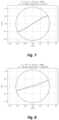
- the foregoing equation can be solved numerically to produce surfaces with different parameters at different filling values (e.g. 50% full).
- the surface of the concrete (dark solid line) as well as a dotted line illustrate near the inner wall of the drum where a sensor would detect an entrance and exit.
- An error in the area measurement based on the perceived surface (as determined by the sensor), and the actual surface was calculated.
- Example 1 Theoretical consideration of the graphic results will confirm further that concrete mixes can demonstrate flow behavior more akin to granular material rather than that of a Newtonian fluid (e.g. the shear-stress within the fluid is linearly proportional to the strain-rate).
- the internal friction of the material is not constant within the concrete. In particular, the internal friction decreases where the material is already moving (i.e. a static versus dynamic friction coefficient). In the case of cascading surfaces, material is already moving in the lower parts of the drum (x ⁇ 0).
- the present inventors believe that a number of factors can affect the shape of the flow surface of the concrete, such that the volume of concrete load actually contained within the rotating drum could deviate significantly from theoretical volume (see dotted line corresponding to entrance and exit points in Fig. 8 ). If errors were constant, then there would be little to worry about. However, the present inventors realized that errors can vary in nature and extent from one mix design to another mix design; and from truck to truck; and from one drum speed to another drum speed; and even from concrete volume to another concrete volume.
- the present inventors prefer to calibrate their load volume determinations using data collected over time.
- this involves using a processor to collect data that includes: submergence state of the sensor probe and other potentially relevant factors such as rheology (e.g., slump), the concrete mix design, and the original or actual beginning volume of the concrete load (as originally batched and placed into the ready-mix delivery truck at the batch plant).
- rheology e.g., slump
- the concrete mix design e.g., the concrete mix design
- the original or actual beginning volume of the concrete load as originally batched and placed into the ready-mix delivery truck at the batch plant.
- this data collection is done before concrete is removed from the drum to establish an initial data set regarding typical drum loads.
- Initial volume was based on the initial batch report from the concrete batching plant. Subsequent volume determinations of the concrete were made by measuring the volume of concrete discharged from the concrete mixer drum into wheel barrows of known volume.
- Tests were performed on the wheel barrows of concrete to determine relevant parameters such as the slump, and air content according to their respective ASTM methods.
- the tilt of the truck (along the rotational axis of the mixer drum) was determined using an inclinometer on the truck, but could be determined using an accelerometer (preferably three-axis type) attached to the rotating drum.
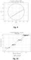
- the relative accuracy of concrete volume determination was assessed by comparing the data with measured volume numbers, as graphically shown in Fig. 10 .
- a linear regression analysis was performed using the submergence/non-submergence (in-and-out) ratio as the predictor variable. Only linear terms were considered (e.g. in-and-out ratio, but not the square of the in-and-out ratio).
- the measured volume numbers were obtained according to the batching facility where the materials are weighed accurately. The percentage of predictions within 0.19 cubic meters (0.25 cubic yards) of the actual volume measurement was determined to be nearly 32% for this example.
- the cross-validation score was determined by using a standard cross validation of the regression method, using a "K-fold" of 5. In other words, the dataset was split into 5 groups where each group is used as a validation set based on models created from the other 4 groups. The present inventors believed that the predictions within each load size group (e.g.
- the present inventors considered that the center of a flowable mass (e.g., Examples 1-3) could change depending upon rheology of the material, and that the amount of cement within the concrete mix could exert a nonlinear change in rheological behavior.
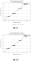
- Fig. 11 they did a linear regression analysis using the entry/exit data (reflected as a ratio of submergence/non-submergence) for each of three different groups of cement content (e.g. 251, 362, 446 kilograms per cubic meter (423, 611 and 752 pounds per cubic yard (pcy))).
- Fig. 11 shows the combined measured versus predicted volumes with their respective linear models.
- the cross-validation score improved by 23.5 percentage points as shown in Fig. 11 , the present inventors believed that a model could be improved in terms of accuracy.
- the present inventors performed a linear regression analysis which included the in-and-out ratio as well as concrete slump (measured according to ASTM C143/143M-15a) as predictor variables for three different cement contents. They also included an interaction term (i.e., between the slump and the in-and-out ratio). In this case, they found that the cross-validation score was improved by an additional 7.1 percentage points, as shown in Fig. 12 . The present inventors believed that overall accuracy could be improved even further.
- the present inventors considered that the tilt of the truck (along the rotational axis of the mixer drum) could adversely affect the volume determination.
- the present inventors performed a linear regression which included as predictor variables the in-and-out ratio, the slump as well as the tilt within each cement content group. The tilt was obtained using an inclinometer mounted on the truck frame (rather than the mixer drum). An interaction term was also included. For this particular data set, the present inventors found that tilt factor provided an additional 17.5 percentage point increase in the cross-validation score; and this can be visually appreciated by referring to Fig. 13 .
- the present inventors applied models using quadratic and cubic terms, including interaction terms for the same parameters of Example 7 (e.g. in-and-out ratio, slump, tilt for each cement group).
- the results of the cubic model are shown in Fig. 14 .
- the predicted points are closer to the line, the cross-validation score decreased by 23.4 percentage points - indicating overfitting of the data.
- this kind of prediction is relatively good for this exact set of data, the prediction is likely to be less accurate when encountering new data (e.g. new loads of concrete with slightly different slumps, tilts, etc.).
- the present inventors saw a similar effect when making modeling predictions that employed quadratic factors.
- a random forest regression is an ensemble learning method that operates by constructing a number of decision trees (in this case 500), and outputting the mean prediction of each individual tree. Decision trees were limited to have a maximum depth of 3 decisions in order to reduce the chance of overfitting.
- the cross-validation score in this case was above 95% and is illustrated in Fig. 16 .
- the present inventors confirmed their belief that, if in-and-out ratio is only used, the cross-validation score drops to below 89%, as shown in Fig. 15 . Thus, the present inventors believe that accuracy of volume prediction might be increased when regression analysis and relevant parameters (e.g. slump, tilt) are included in the analytical model.
- the present inventors provide a histogram in Fig. 16 to suggest the potential available volume calibration data that can be obtained, as illustrated by the exemplary methods discussed above. Although a majority of concrete load volumes are about 6.9-7.6 cubic meters (9-10 cubic yards), the present inventors believe that significant data can be obtained with various load sizes. As time progresses, more data is generated and thus available for use in calibration methods, such as in the examples described above.
Landscapes
- Structural Engineering (AREA)
- Mechanical Engineering (AREA)
- Engineering & Computer Science (AREA)
- Chemical & Material Sciences (AREA)
- Dispersion Chemistry (AREA)
- General Health & Medical Sciences (AREA)
- Physics & Mathematics (AREA)
- General Physics & Mathematics (AREA)
- Immunology (AREA)
- Pathology (AREA)
- Biochemistry (AREA)
- Analytical Chemistry (AREA)
- Life Sciences & Earth Sciences (AREA)
- Health & Medical Sciences (AREA)
- Preparation Of Clay, And Manufacture Of Mixtures Containing Clay Or Cement (AREA)
Claims (15)
- Verfahren zum Bestimmen des Volumens einer Betonladung (12, 22, 32, 42), umfassend:(A) Drehen einer Betonladung (12, 22, 32, 42), die in einer Mischertrommel (10) enthalten ist, die eine Innenwand, eine nicht-vertikale Drehachse und wenigstens eine Sensorsonde (14) aufweist, die an oder entlang der Innenwand montiert ist und dazu konfiguriert ist, ein- und ausgehende Signaldaten, wenn sie durch die enthaltene Betonladung (12, 22, 32, 42) gedreht wird, unter Verwendung von (i) Sondeneintauch- und Nicht-Eintauchintervallen oder (ii) Sondeneintrittswinkel und -austrittswinkel an einen Prozessor (18) zu übertragen, der dazu konfiguriert ist, die ein- und ausgehenden Signaldaten zu empfangen und einen Wert zu berechnen, der dem Volumen der Betonladung (12, 22, 32, 42) entspricht;(B) der Prozessor (18) die Volumenwertberechnung durch Zugreifen auf eine Datenbank mit gespeicherten Werten von Betonladungsvolumina durchführt, wie mit ein- und ausgehenden Signaldaten, die zuvor von Sensorsonden erhalten wurden, korreliert; und(C) Durchführen auf Grundlage der Volumenwertberechnung wenigstens einer Funktion, ausgewählt aus (i) Verabreichen einer Wasser- oder Zusatzmitteldosierung in die Betonladung (12, 22, 32, 42), (ii) Ausstoßen eines Betonvolumens aus der Mischertrommel (10), (iii) Bereitstellen einer Anzeige für die verabreichte Dosierung, das ausgestoßene Betonvolumen oder für beides; und (iv) eine Kombination aus einer der vorgenannten Funktionen; wobei das Verfahren ferner umfasst:(D) Überwachen wenigstens eines/einer von: Rheologie der Betonladung (12, 22, 32, 42) die in der rotierenden Mischertrommel (10) enthalten ist; Neigungswinkel der rotierenden Mischertrommel (10) oder beides; und gekennzeichnet durchDurchführen der Berechnung des Volumenwerts durch Zugreifen auf eine Datenbank mit gespeicherten Werten von Betonladungsvolumina, wie mit ein- und ausgehenden Signaldaten, die zuvor von Sensorsonden bei verschiedenen Trommeldrehzahlen, bei verschiedenen rheologischen Bedingungen und bei verschiedenen Neigungswinkeln der Mischertrommel (10) erhalten wurden, korreliert.
- Verfahren nach Anspruch 1, wobei in Schritt (A) die Berechnung eines Wertvolumens der Betonladung (12, 22, 32, 42), die in der Mischertrommel (10) enthalten ist, die Anpassung eines Betonladungsvolumens, wie in oder auf einem Chargenticket beinhaltet, das durch eine Transportbetonwerk ausgegeben wird, umfasst.
- Verfahren nach Anspruch 1 oder Anspruch 2, wobei die drehbare Betonmischertrommel (10) auf einem Transportbetonlieferwagen montiert ist.
- Verfahren nach einem der Ansprüche 1-3, wobei die Setzung einer aktuellen Betonladung (12, 22, 32, 42) in der Mischertrommel (10) durch ein automatisches Setzungsüberwachungssystem überwacht wird, wobei der Setzungswert unter Verwendung eines Kraftsensors, eines Hydraulikdrucksensors oder einer Kombination davon abgeleitet wird.
- Verfahren nach einem der Ansprüche 1-4, wobei die wenigstens eine Sensorprobe (14) ein Kontaktschalter ist.
- Verfahren nach einem der Ansprüche 1-5, ferner umfassend das Bereitstellen wenigstens eines Hydraulikdrucksensors zum Überwachen des Drucks, der erforderlich ist, um die Betonmischtrommel (10) bei einer bestimmten Trommeldrehzahl zu drehen und eine Anzeige der Setzung, des Setzungsflusses oder anderer rheologischer Eigenschaften der aktuellen Betonladung (12, 22, 32, 42) in der Mischertrommel (10) zu erhalten; und das Einsetzen der wenigstens einen Sensorsonde (14), um ein- und ausgehende Daten für die aktuelle Betonladung (12, 22, 32, 42), die in der Mischertrommel (10) enthalten ist, zu erzeugen, um einen Volumenwert für eine gegebene Trommeldrehzahl zu berechnen, und das Vergleichen der Anzeige der Setzung, des Setzungsflusses oder anderer rheologischer Merkmale der aktuellen Betonladung (12, 22, 32, 42) auf Grundlage des Hydraulikdrucks und der Trommeldrehzahl mit historischen Signaldaten, in denen ein- und ausgehende Daten in Korrelation mit der berechneten Setzung, des Setzungsflusses oder anderen rheologischen Merkmalen bei verschiedenen Trommeldrehzahlen gespeichert wurden.
- Verfahren nach einem der Ansprüche 1-6, wobei die wenigstens eine Sensorsonde (14) eine Kraftsonde und einen Kontaktschalter umfasst, die beide an einer Lukentür der Mischertrommel (10) montiert sind
- Verfahren nach Anspruch 7, wobei sowohl die Kraftsonde als auch der Kontaktschalter ein- und ausgehende Signaldaten an denselben Prozessor (18) bereitstellen und verglichen werden, um festzustellen, ob die Kraftsonde aufgrund von Variationen in der Länge der Kraftsonde und den tatsächlichen Stellen auf der Betonoberfläche aufweist, in die die Kraftsonde eintritt und austritt.
- Verfahren nach einem der Ansprüche 1-8, wobei die ein- und ausgehenden Sondensignaldaten, die von der aktuellen Betonladung (12, 22, 32, 42), die in der drehenden Mischertrommel (10) enthalten ist, von dem Prozessor (18) erst dann verwendet werden, nachdem (i) eine vorbestimmte Anzahl von Drehungen der Mischertrommel (10) stattgefunden hat oder (ii) ein automatisches Setzungsüberwachungssystem bestätigt hat, dass die Betonladung (12, 22, 32, 42) Homogenität oder Gleichmäßigkeit erreicht hat.
- Verfahren nach einem der Ansprüche 1-9, ferner umfassend das Erhalten eines ein- und ausgehenden Signals der Sensorsonde (14), das Datensätze von Sondeneintrittspunkt, Sondenaustrittspunkt, Drehzahl der Mischertrommel (10) und Senkungswerte umfasst, und wobei ferner ein Prozessor (18) diese Datensätze mit einer aktuellen Betonladung (12, 22, 32, 42) in der Mischertrommel (10) vergleicht und sie mit historischen Daten vergangener Betonladungen vergleicht.
- Verfahren nach einem der Ansprüche 1-10, ferner umfassend das Erhalten von ein- und ausgehenden Datensignalen der Sensorprobe (14), die Datensätze umfassen, die den Eintrittspunkt der Sonde, den Austrittspunkt der Sonde, die Drehzahl der Mischertrommel (10), die Setzung umfassen; wobei der Prozessor (18) diese Datensätze, die von einer aktuellen Betonladung (12, 22, 32, 42) in der Mischertrommel (10) erhalten werden, mit gespeicherten Daten vergangener Betonladungen vergleicht, wobei der Prozessor (18) ferner die Mischungsauslegungszahl und den Neigungswinkel der aktuellen Betonladung (12, 22, 32, 42) mit den gespeicherten Daten vergangener Betonladungen vergleicht.
- Verfahren nach einem der Ansprüche 1-11, wobei der Prozessor (18) historische ein- und ausgehende Sensorsondendaten, die in dem Speicher gespeichert sind, auf Grundlage des Mischertrommeltyps (10) auswählt.
- Verfahren nach einem der Ansprüche 1-12, ferner umfassend das Überwachen der Setzung und des Neigungswinkels von der Betonladung (12, 22, 32, 42), die in der Mischertrommel (10) enthalten ist, und das Durchführen der Volumenwertberechnung durch Zugreifen auf eine Datenbank mit gespeicherten Werten von Betonladungsvolumina, wie mit ein- und ausgehenden Signaldaten, die von Sensorsonden bei verschiedenen Trommeldrehzahlen, bei verschiedenen rheologischen Bedingungen und verschiedenen Neigungswinkeln der Mischertrommel (10) zuvor erhalten wurden, korreliert, wobei der Prozessor (18) ferner dazu konfiguriert ist, Daten in die Datenbank relativ zu den überwachten ein- und ausgehenden Signaldaten, der Drehzahl der Mischertrommel (10), der Senkung, des Neigungswinkels und den berechneten Werten des Volumen der Betonladung (12, 22, 32, 42) zu speichern.
- Verfahren nach einem der Ansprüche 1-13, ferner umfassend das Überwachen der Setzung und des Neigungswinkels der Betonladung (12, 22, 32, 42), die in der Mischertrommel (10) enthalten ist, und das Durchführen der Berechnung der Volumenwertberechnung durch Zugreifen auf eine Datenbank mit gespeicherten Werten von Betonladungsvolumina, wie mit ein- und ausgehenden Signaldaten, die von Sensorsonden bei verschiedenen Trommeldrehzahlen, bei verschiedenen rheologischen Bedingungen und verschiedenen Neigungswinkeln der Mischertrommel (10) zuvor erhalten wurden, korreliert, wobei der Prozessor (18) ferner dazu konfiguriert ist, Daten in die Datenbank relativ zu den überwachten ein- und ausgehenden Signaldaten, der Drehzahl der Mischertrommel (10), der Senkung, des Neigungswinkels und den berechneten Werten des Volumen der Betonladung (12, 22, 32, 42) zu speichern; und wobei ferner die Trommeldrehgeschwindigkeit innerhalb des Bereichs von 1 bis 16 Umdrehungen pro Minute (U/min) und stärker bevorzugt 1-22 Umdrehungen pro Minute liegt; und wobei ferner die Senkung innerhalb des Bereichs von 1-25 cm (0,5-10 Zoll) liegt oder die Senkung innerhalb des Bereichs von 25-51 cm (10-20 Zoll) liegt; und wobei der Neigungswinkel der Trommel zwischen (-)10 Grad bis (+)10 Grad Abweichung liegt, wie gemessen, wenn die Trommel geneigt wird, wie durch das Fahren des Lieferwagens entlang einer aufwärts oder abwärts geneigten Fahrbahn.
- System, umfassend einen Prozessor und wenigstens eine Sensorsonde (14) in Kommunikation (16) mit dem Prozessor (18);wobei das System ferner eine Mischertrommel (10) mit einer Innenwand und einer nicht-vertikalen Drehachse umfasst;wobei die wenigstens eine Sensorsonde (14) ist: (i) an oder entlang der Innenwand montiert; und (ii) dazu konfiguriert ist, ein- und ausgehende Signaldaten, wenn sie durch eine Betonladung (12, 22, 32, 42) gedreht wird, die innerhalb der Mischertrommel (10) enthalten ist, zu übertragen, dadurch gekennzeichnet, dass der Prozessor programmiert ist, das Verfahren nach einem der Ansprüche 1-14 durchzuführen.
Applications Claiming Priority (2)
| Application Number | Priority Date | Filing Date | Title |
|---|---|---|---|
| US201962881583P | 2019-08-01 | 2019-08-01 | |
| PCT/US2020/044153 WO2021021983A1 (en) | 2019-08-01 | 2020-07-30 | Rotated concrete volume determination |
Publications (3)
| Publication Number | Publication Date |
|---|---|
| EP4007902A1 EP4007902A1 (de) | 2022-06-08 |
| EP4007902A4 EP4007902A4 (de) | 2023-08-02 |
| EP4007902B1 true EP4007902B1 (de) | 2025-01-08 |
Family
ID=74229317
Family Applications (1)
| Application Number | Title | Priority Date | Filing Date |
|---|---|---|---|
| EP20847825.5A Active EP4007902B1 (de) | 2019-08-01 | 2020-07-30 | Drehbetonvolumenbestimmung |
Country Status (9)
| Country | Link |
|---|---|
| US (1) | US11331829B2 (de) |
| EP (1) | EP4007902B1 (de) |
| JP (1) | JP7737356B2 (de) |
| KR (1) | KR102924558B1 (de) |
| CN (1) | CN114424043B (de) |
| AU (1) | AU2020323943B2 (de) |
| CA (1) | CA3148986A1 (de) |
| MX (1) | MX2022001157A (de) |
| WO (1) | WO2021021983A1 (de) |
Families Citing this family (13)
| Publication number | Priority date | Publication date | Assignee | Title |
|---|---|---|---|---|
| EP3558611B1 (de) * | 2016-12-22 | 2020-11-18 | Command Alkon Incorporated | Verfahren und systeme zur handhabung von frischem beton |
| EP4227055A1 (de) * | 2017-02-21 | 2023-08-16 | Verifi LLC | Verfahren zur überwachung von betonbestandteilen |
| EP3673245B1 (de) | 2017-08-22 | 2024-10-09 | Cidra Corporate Services LLC | System zur bestimmung des volumens und / oder der viskosität von beton in einem rotierenden behälter |
| US11402312B2 (en) * | 2018-02-08 | 2022-08-02 | Command Alkon Incorporated | Methods and systems for handling fresh concrete based on hydraulic pressure and on rheological probe pressure |
| US11420357B2 (en) * | 2018-05-02 | 2022-08-23 | Command Alkon Incorporated | System having drum discharge outlet sensors and method of characterizing fresh concrete delivery using same |
| US11224989B2 (en) * | 2018-05-02 | 2022-01-18 | Command Alkon Incorporated | Methods for determining fresh concrete discharge volume and discharge flow rate and system using same |
| CA3148986A1 (en) * | 2019-08-01 | 2021-02-04 | Gcp Applied Technologies Inc. | Rotated concrete volume determination |
| CN111912746B (zh) * | 2020-06-09 | 2022-08-02 | 广西大学 | 基于底部阻力分析混凝土和易性的定量评估方法 |
| CA3148540A1 (en) * | 2021-02-11 | 2022-08-11 | Command Alkon Incorporated | Method and system for detecting segregation occuring in a fresh concrete mixture agitated in a mixer drum |
| WO2022256165A1 (en) * | 2021-06-04 | 2022-12-08 | Oshkosh Corporation | Mixer vehicle system and method of remote management |
| JP2023116193A (ja) * | 2022-02-09 | 2023-08-22 | GNN Machinery Japan 株式会社 | 流動性計測方法、流動性計測装置、並びに流動性計測システム |
| WO2023230314A1 (en) * | 2022-05-27 | 2023-11-30 | Command Alkon Incorporated | Methods of loading concrete ingredients into a drum of a concrete mixer truck and system therefore |
| CN115366260B (zh) * | 2022-08-23 | 2024-05-28 | 中联重科股份有限公司 | 搅拌车及用于确定搅拌物实际质量的方法 |
Family Cites Families (51)
| Publication number | Priority date | Publication date | Assignee | Title |
|---|---|---|---|---|
| US2324304A (en) | 1939-08-24 | 1943-07-13 | Katzman Jacob | Turbidity meter |
| US2999381A (en) | 1958-04-23 | 1961-09-12 | Industrial Nucleonics Corp | Nuclear magnetic resonance measuring system |
| JPS5296096A (en) | 1976-02-06 | 1977-08-12 | Matsushita Electric Ind Co Ltd | Water-content detecting apparatus |
| US4263511A (en) | 1978-12-29 | 1981-04-21 | University Of Miami | Turbidity meter |
| FR2486656A1 (fr) | 1980-07-09 | 1982-01-15 | Commissariat Energie Atomique | Hygrometre capacitif |
| US4780665A (en) | 1986-09-30 | 1988-10-25 | Deere & Company | Apparatus and method for controlling sand moisture |
| US5127740A (en) * | 1991-07-03 | 1992-07-07 | Resource Recovery Systems, Inc. | Concrete reclamation system and method for utilizing same |
| AUPN296495A0 (en) * | 1995-05-15 | 1995-06-08 | Boral Resources (Vic) Pty Limited | Concrete mixing |
| JPH08332625A (ja) * | 1995-06-06 | 1996-12-17 | Nikko Co Ltd | 生コンクリート製造方法 |
| FR2751911B1 (fr) * | 1996-07-31 | 2000-06-16 | Mbt Holding Ag | Systeme de controle et de distribution pour malaxeur a beton et procede d'utilisation |
| AU2001261200B2 (en) * | 2000-05-04 | 2006-02-09 | Oregon Health Sciences University | Endovascular stent graft |
| US8727608B2 (en) | 2003-09-04 | 2014-05-20 | Flir Systems, Inc. | Moisture meter with non-contact infrared thermometer |
| EP1720689B1 (de) | 2004-02-13 | 2017-03-22 | Verifi LLC | Verfahren und system zum berechnen und melden von absetzungen in lieferfahrzeugen |
| US7033321B1 (en) | 2004-10-25 | 2006-04-25 | Artann Laboratories, Inc. | Ultrasonic water content monitor and methods for monitoring tissue hydration |
| ES2281267B1 (es) | 2005-11-28 | 2008-09-01 | Eugenio Bonilla Benegas | Sistema de monitorizacion del amasado de conglomerados. |
| US8020431B2 (en) * | 2007-06-19 | 2011-09-20 | Verifi, LLC | Method and system for calculating and reporting slump in delivery vehicles |
| US8989905B2 (en) | 2007-06-19 | 2015-03-24 | Verifi Llc | Method and system for calculating and reporting slump in delivery vehicles |
| US8764272B2 (en) | 2008-04-07 | 2014-07-01 | W. R. Grace & Co., -Conn. | Method for monitoring thixotropy in concrete mixing drum |
| US8858061B2 (en) * | 2008-05-28 | 2014-10-14 | Dully Katzeff-Berman | Concrete slump measurement and control system |
| JP5713524B2 (ja) * | 2008-07-11 | 2015-05-07 | ダブリュー・アール・グレイス・アンド・カンパニー−コネチカット | コンクリートにおける粘土活性を改善するためのスランプ保持混和剤 |
| WO2010110814A1 (en) * | 2009-03-27 | 2010-09-30 | Gr 2008 Llc | Slump flow monitoring |
| JP5730847B2 (ja) * | 2009-03-27 | 2015-06-10 | ベリフアイ・エルエルシー | コンクリートの監視及び制御のためのミキサー波形分析 |
| US8758583B2 (en) | 2009-04-28 | 2014-06-24 | Abbott Diabetes Care Inc. | Smart sensor ports and methods of using same |
| US8557070B2 (en) * | 2009-09-14 | 2013-10-15 | Joel A. Stanley | Method of mounting objects to polymeric membranes |
| US10520410B2 (en) * | 2009-10-07 | 2019-12-31 | Command Alkon Incorporated | Probe and method for obtaining rheological property value |
| WO2011042880A1 (en) * | 2009-10-07 | 2011-04-14 | I.B.B. Rheologie Inc. | Probe and method for obtaining rheological property value |
| US9789629B2 (en) | 2010-06-23 | 2017-10-17 | Verifi Llc | Method for adjusting concrete rheology based upon nominal dose-response profile |
| US8311678B2 (en) | 2010-06-23 | 2012-11-13 | Verifi Llc | Method for adjusting concrete rheology based upon nominal dose-response profile |
| DE202010012841U1 (de) | 2010-09-22 | 2010-12-02 | Franz Ludwig Gmbh | Trommelmischer mit Messsonde |
| MX345937B (es) * | 2011-12-12 | 2017-02-27 | Verifi Llc | Gestion multivariada del aire atrapado y reologia en mezclas cementosas. |
| FR2988847B1 (fr) * | 2012-03-30 | 2014-04-11 | Lafarge Sa | Procede de controle d'un parametre d'ouvrabilite d'un beton dans un malaxeur |
| US9550312B2 (en) | 2012-10-15 | 2017-01-24 | Verifi Llc | Treating and reporting volume of concrete in delivery vehicle mixing drum |
| CA2887601C (en) | 2012-10-15 | 2020-08-25 | Verifi Llc | Sneak water detection for concrete delivery vehicles |
| WO2014108798A2 (en) * | 2013-01-11 | 2014-07-17 | Katzeff-Berman, Dully | Concrete mixture measurement sensor, system and method |
| MX2016004820A (es) * | 2013-10-18 | 2016-11-11 | Gcp Applied Tech Inc | Tiempo de respuesta rapida en sistemas de monitorizacion de asentamientos. |
| WO2015073825A1 (en) | 2013-11-15 | 2015-05-21 | Verifi Llc | Gyroscopic rotational monitoring system |
| EP3131722B1 (de) | 2014-04-14 | 2021-07-21 | Verifi LLC | Dynamische trennungsüberwachung von beton |
| BR112017001485A2 (pt) * | 2014-07-24 | 2017-12-05 | Gcp Applied Tech Inc | monitoramento de mistura de concreto autolimpante |
| WO2016023119A1 (en) | 2014-08-15 | 2016-02-18 | I.B.B. Rheologie Inc. | Method and system for handling ready-mix concrete and method for producing calibration data |
| MY186502A (en) * | 2015-06-04 | 2021-07-22 | Verifi Llc | Post-batching cma dosing into concrete |
| US10583581B2 (en) * | 2015-09-21 | 2020-03-10 | Flashfill Services, Llc | Volumetric mobile powder mixer |
| CN109070385B (zh) * | 2015-12-07 | 2020-07-17 | 威瑞飞有限责任公司 | 宽速度范围混凝土监测校准 |
| US10987829B2 (en) * | 2016-06-17 | 2021-04-27 | Oshkosh Corporation | Concrete drum control, property prediction, and monitoring systems and methods |
| WO2018005460A1 (en) * | 2016-06-27 | 2018-01-04 | Quipip, Llc | Sensing device, and systems and methods for obtaining data relating to concrete mixtures and concrete structures |
| MY197224A (en) * | 2016-09-26 | 2023-06-06 | Verifi Llc | Pre-pour slump maximization of delivered concrete |
| JP6410896B1 (ja) * | 2017-07-26 | 2018-10-24 | Kyb株式会社 | 生コンクリート量推定装置、生コンクリート量推定方法及びミキサ車 |
| PT3664925T (pt) | 2017-08-11 | 2024-04-16 | Gcp Applied Tech Inc | Medição de água cinzenta |
| EP3673245B1 (de) | 2017-08-22 | 2024-10-09 | Cidra Corporate Services LLC | System zur bestimmung des volumens und / oder der viskosität von beton in einem rotierenden behälter |
| CA3086587A1 (en) * | 2017-12-22 | 2019-06-27 | Verifi Llc | Managing concrete mix design catalogs |
| US11224989B2 (en) * | 2018-05-02 | 2022-01-18 | Command Alkon Incorporated | Methods for determining fresh concrete discharge volume and discharge flow rate and system using same |
| CA3148986A1 (en) * | 2019-08-01 | 2021-02-04 | Gcp Applied Technologies Inc. | Rotated concrete volume determination |
-
2020
- 2020-07-30 CA CA3148986A patent/CA3148986A1/en active Pending
- 2020-07-30 CN CN202080069323.XA patent/CN114424043B/zh active Active
- 2020-07-30 MX MX2022001157A patent/MX2022001157A/es unknown
- 2020-07-30 WO PCT/US2020/044153 patent/WO2021021983A1/en not_active Ceased
- 2020-07-30 JP JP2022506785A patent/JP7737356B2/ja active Active
- 2020-07-30 EP EP20847825.5A patent/EP4007902B1/de active Active
- 2020-07-30 AU AU2020323943A patent/AU2020323943B2/en active Active
- 2020-07-30 US US16/942,972 patent/US11331829B2/en active Active
- 2020-07-30 KR KR1020227005721A patent/KR102924558B1/ko active Active
Also Published As
| Publication number | Publication date |
|---|---|
| CN114424043B (zh) | 2025-06-06 |
| CN114424043A (zh) | 2022-04-29 |
| CA3148986A1 (en) | 2021-02-04 |
| MX2022001157A (es) | 2022-04-11 |
| AU2020323943A1 (en) | 2022-03-03 |
| US11331829B2 (en) | 2022-05-17 |
| KR102924558B1 (ko) | 2026-02-05 |
| EP4007902A1 (de) | 2022-06-08 |
| JP7737356B2 (ja) | 2025-09-10 |
| JP2022543255A (ja) | 2022-10-11 |
| BR112022001752A2 (pt) | 2022-04-12 |
| AU2020323943B2 (en) | 2025-05-29 |
| WO2021021983A1 (en) | 2021-02-04 |
| US20210031407A1 (en) | 2021-02-04 |
| KR20220103089A (ko) | 2022-07-21 |
| EP4007902A4 (de) | 2023-08-02 |
Similar Documents
| Publication | Publication Date | Title |
|---|---|---|
| EP4007902B1 (de) | Drehbetonvolumenbestimmung | |
| CN111163858B (zh) | 灰水测量 | |
| EP2906399B1 (de) | Verfahren und system zur meldung von betonmengen in einem lieferfahrzeug mit mischtrommel | |
| EP2296854B1 (de) | Steuersystem zur messung des betonsetzmasses | |
| US10363684B2 (en) | Monitoring discharge pressure on concrete mix load | |
| AU663486B2 (en) | System for control of the condition of mixed concrete | |
| EP2906400B1 (de) | Kriechwassererkennung für betonlieferfahrzeuge | |
| EP4198509B1 (de) | Kalibrierung der betonüberwachung mit breitem geschwindigkeitsbereich | |
| US20210031408A1 (en) | System having drum discharge outlet sensors and method of characterizing fresh concrete delivery using same | |
| HK40073555A (en) | Rotated concrete volume determination | |
| HK40073555B (zh) | 旋转混凝土体积确定 | |
| BR112022001752B1 (pt) | Sistema e método para determinar o volume de uma carga de concreto | |
| HK40081222A (en) | Grey water measurement | |
| AU3531100A (en) | Concrete mixing | |
| HK40081222B (zh) | 灰水测量 | |
| HK40030356B (en) | Grey water measurement | |
| HK40030356A (en) | Grey water measurement |
Legal Events
| Date | Code | Title | Description |
|---|---|---|---|
| STAA | Information on the status of an ep patent application or granted ep patent |
Free format text: STATUS: THE INTERNATIONAL PUBLICATION HAS BEEN MADE |
|
| PUAI | Public reference made under article 153(3) epc to a published international application that has entered the european phase |
Free format text: ORIGINAL CODE: 0009012 |
|
| STAA | Information on the status of an ep patent application or granted ep patent |
Free format text: STATUS: REQUEST FOR EXAMINATION WAS MADE |
|
| 17P | Request for examination filed |
Effective date: 20220126 |
|
| AK | Designated contracting states |
Kind code of ref document: A1 Designated state(s): AL AT BE BG CH CY CZ DE DK EE ES FI FR GB GR HR HU IE IS IT LI LT LU LV MC MK MT NL NO PL PT RO RS SE SI SK SM TR |
|
| DAV | Request for validation of the european patent (deleted) | ||
| DAX | Request for extension of the european patent (deleted) | ||
| REG | Reference to a national code |
Ref country code: DE Ref legal event code: R079 Free format text: PREVIOUS MAIN CLASS: G01N0011140000 Ipc: B28C0005420000 Ref country code: DE Ref legal event code: R079 Ref document number: 602020044614 Country of ref document: DE Free format text: PREVIOUS MAIN CLASS: G01N0011140000 Ipc: B28C0005420000 |
|
| A4 | Supplementary search report drawn up and despatched |
Effective date: 20230630 |
|
| RIC1 | Information provided on ipc code assigned before grant |
Ipc: G01N 11/14 20060101ALI20230626BHEP Ipc: B28C 7/02 20060101ALI20230626BHEP Ipc: B28C 5/42 20060101AFI20230626BHEP |
|
| GRAP | Despatch of communication of intention to grant a patent |
Free format text: ORIGINAL CODE: EPIDOSNIGR1 |
|
| STAA | Information on the status of an ep patent application or granted ep patent |
Free format text: STATUS: GRANT OF PATENT IS INTENDED |
|
| INTG | Intention to grant announced |
Effective date: 20241008 |
|
| GRAS | Grant fee paid |
Free format text: ORIGINAL CODE: EPIDOSNIGR3 |
|
| GRAA | (expected) grant |
Free format text: ORIGINAL CODE: 0009210 |
|
| STAA | Information on the status of an ep patent application or granted ep patent |
Free format text: STATUS: THE PATENT HAS BEEN GRANTED |
|
| P01 | Opt-out of the competence of the unified patent court (upc) registered |
Free format text: CASE NUMBER: APP_61881/2024 Effective date: 20241119 |
|
| RAP3 | Party data changed (applicant data changed or rights of an application transferred) |
Owner name: GCP APPLIED TECHNOLOGIES INC. |
|
| AK | Designated contracting states |
Kind code of ref document: B1 Designated state(s): AL AT BE BG CH CY CZ DE DK EE ES FI FR GB GR HR HU IE IS IT LI LT LU LV MC MK MT NL NO PL PT RO RS SE SI SK SM TR |
|
| REG | Reference to a national code |
Ref country code: GB Ref legal event code: FG4D |
|
| REG | Reference to a national code |
Ref country code: CH Ref legal event code: EP |
|
| REG | Reference to a national code |
Ref country code: DE Ref legal event code: R096 Ref document number: 602020044614 Country of ref document: DE |
|
| REG | Reference to a national code |
Ref country code: IE Ref legal event code: FG4D |
|
| REG | Reference to a national code |
Ref country code: SE Ref legal event code: TRGR |
|
| REG | Reference to a national code |
Ref country code: LT Ref legal event code: MG9D |
|
| REG | Reference to a national code |
Ref country code: NL Ref legal event code: MP Effective date: 20250108 |
|
| REG | Reference to a national code |
Ref country code: AT Ref legal event code: MK05 Ref document number: 1758048 Country of ref document: AT Kind code of ref document: T Effective date: 20250108 |
|
| PG25 | Lapsed in a contracting state [announced via postgrant information from national office to epo] |
Ref country code: NL Free format text: LAPSE BECAUSE OF FAILURE TO SUBMIT A TRANSLATION OF THE DESCRIPTION OR TO PAY THE FEE WITHIN THE PRESCRIBED TIME-LIMIT Effective date: 20250108 |
|
| PG25 | Lapsed in a contracting state [announced via postgrant information from national office to epo] |
Ref country code: RS Free format text: LAPSE BECAUSE OF FAILURE TO SUBMIT A TRANSLATION OF THE DESCRIPTION OR TO PAY THE FEE WITHIN THE PRESCRIBED TIME-LIMIT Effective date: 20250408 |
|
| PG25 | Lapsed in a contracting state [announced via postgrant information from national office to epo] |
Ref country code: FI Free format text: LAPSE BECAUSE OF FAILURE TO SUBMIT A TRANSLATION OF THE DESCRIPTION OR TO PAY THE FEE WITHIN THE PRESCRIBED TIME-LIMIT Effective date: 20250108 |
|
| PG25 | Lapsed in a contracting state [announced via postgrant information from national office to epo] |
Ref country code: PL Free format text: LAPSE BECAUSE OF FAILURE TO SUBMIT A TRANSLATION OF THE DESCRIPTION OR TO PAY THE FEE WITHIN THE PRESCRIBED TIME-LIMIT Effective date: 20250108 |
|
| PG25 | Lapsed in a contracting state [announced via postgrant information from national office to epo] |
Ref country code: ES Free format text: LAPSE BECAUSE OF FAILURE TO SUBMIT A TRANSLATION OF THE DESCRIPTION OR TO PAY THE FEE WITHIN THE PRESCRIBED TIME-LIMIT Effective date: 20250108 |
|
| PGFP | Annual fee paid to national office [announced via postgrant information from national office to epo] |
Ref country code: GB Payment date: 20250619 Year of fee payment: 6 |
|
| PG25 | Lapsed in a contracting state [announced via postgrant information from national office to epo] |
Ref country code: NO Free format text: LAPSE BECAUSE OF FAILURE TO SUBMIT A TRANSLATION OF THE DESCRIPTION OR TO PAY THE FEE WITHIN THE PRESCRIBED TIME-LIMIT Effective date: 20250408 Ref country code: IS Free format text: LAPSE BECAUSE OF FAILURE TO SUBMIT A TRANSLATION OF THE DESCRIPTION OR TO PAY THE FEE WITHIN THE PRESCRIBED TIME-LIMIT Effective date: 20250508 |
|
| PG25 | Lapsed in a contracting state [announced via postgrant information from national office to epo] |
Ref country code: HR Free format text: LAPSE BECAUSE OF FAILURE TO SUBMIT A TRANSLATION OF THE DESCRIPTION OR TO PAY THE FEE WITHIN THE PRESCRIBED TIME-LIMIT Effective date: 20250108 |
|
| PG25 | Lapsed in a contracting state [announced via postgrant information from national office to epo] |
Ref country code: LV Free format text: LAPSE BECAUSE OF FAILURE TO SUBMIT A TRANSLATION OF THE DESCRIPTION OR TO PAY THE FEE WITHIN THE PRESCRIBED TIME-LIMIT Effective date: 20250108 Ref country code: PT Free format text: LAPSE BECAUSE OF FAILURE TO SUBMIT A TRANSLATION OF THE DESCRIPTION OR TO PAY THE FEE WITHIN THE PRESCRIBED TIME-LIMIT Effective date: 20250508 |
|
| PGFP | Annual fee paid to national office [announced via postgrant information from national office to epo] |
Ref country code: FR Payment date: 20250620 Year of fee payment: 6 |
|
| PG25 | Lapsed in a contracting state [announced via postgrant information from national office to epo] |
Ref country code: GR Free format text: LAPSE BECAUSE OF FAILURE TO SUBMIT A TRANSLATION OF THE DESCRIPTION OR TO PAY THE FEE WITHIN THE PRESCRIBED TIME-LIMIT Effective date: 20250409 Ref country code: BG Free format text: LAPSE BECAUSE OF FAILURE TO SUBMIT A TRANSLATION OF THE DESCRIPTION OR TO PAY THE FEE WITHIN THE PRESCRIBED TIME-LIMIT Effective date: 20250108 |
|
| PG25 | Lapsed in a contracting state [announced via postgrant information from national office to epo] |
Ref country code: AT Free format text: LAPSE BECAUSE OF FAILURE TO SUBMIT A TRANSLATION OF THE DESCRIPTION OR TO PAY THE FEE WITHIN THE PRESCRIBED TIME-LIMIT Effective date: 20250108 |
|
| PGFP | Annual fee paid to national office [announced via postgrant information from national office to epo] |
Ref country code: SE Payment date: 20250619 Year of fee payment: 6 |
|
| PG25 | Lapsed in a contracting state [announced via postgrant information from national office to epo] |
Ref country code: SM Free format text: LAPSE BECAUSE OF FAILURE TO SUBMIT A TRANSLATION OF THE DESCRIPTION OR TO PAY THE FEE WITHIN THE PRESCRIBED TIME-LIMIT Effective date: 20250108 |
|
| REG | Reference to a national code |
Ref country code: DE Ref legal event code: R097 Ref document number: 602020044614 Country of ref document: DE |
|
| PG25 | Lapsed in a contracting state [announced via postgrant information from national office to epo] |
Ref country code: DK Free format text: LAPSE BECAUSE OF FAILURE TO SUBMIT A TRANSLATION OF THE DESCRIPTION OR TO PAY THE FEE WITHIN THE PRESCRIBED TIME-LIMIT Effective date: 20250108 |
|
| PGFP | Annual fee paid to national office [announced via postgrant information from national office to epo] |
Ref country code: DE Payment date: 20250620 Year of fee payment: 6 |
|
| PG25 | Lapsed in a contracting state [announced via postgrant information from national office to epo] |
Ref country code: EE Free format text: LAPSE BECAUSE OF FAILURE TO SUBMIT A TRANSLATION OF THE DESCRIPTION OR TO PAY THE FEE WITHIN THE PRESCRIBED TIME-LIMIT Effective date: 20250108 Ref country code: CZ Free format text: LAPSE BECAUSE OF FAILURE TO SUBMIT A TRANSLATION OF THE DESCRIPTION OR TO PAY THE FEE WITHIN THE PRESCRIBED TIME-LIMIT Effective date: 20250108 |
|
| PG25 | Lapsed in a contracting state [announced via postgrant information from national office to epo] |
Ref country code: RO Free format text: LAPSE BECAUSE OF FAILURE TO SUBMIT A TRANSLATION OF THE DESCRIPTION OR TO PAY THE FEE WITHIN THE PRESCRIBED TIME-LIMIT Effective date: 20250108 |
|
| PG25 | Lapsed in a contracting state [announced via postgrant information from national office to epo] |
Ref country code: SK Free format text: LAPSE BECAUSE OF FAILURE TO SUBMIT A TRANSLATION OF THE DESCRIPTION OR TO PAY THE FEE WITHIN THE PRESCRIBED TIME-LIMIT Effective date: 20250108 |
|
| PLBE | No opposition filed within time limit |
Free format text: ORIGINAL CODE: 0009261 |
|
| STAA | Information on the status of an ep patent application or granted ep patent |
Free format text: STATUS: NO OPPOSITION FILED WITHIN TIME LIMIT |
|
| REG | Reference to a national code |
Ref country code: CH Ref legal event code: L10 Free format text: ST27 STATUS EVENT CODE: U-0-0-L10-L00 (AS PROVIDED BY THE NATIONAL OFFICE) Effective date: 20251119 |
|
| 26N | No opposition filed |
Effective date: 20251009 |
|
| PG25 | Lapsed in a contracting state [announced via postgrant information from national office to epo] |
Ref country code: IT Free format text: LAPSE BECAUSE OF FAILURE TO SUBMIT A TRANSLATION OF THE DESCRIPTION OR TO PAY THE FEE WITHIN THE PRESCRIBED TIME-LIMIT Effective date: 20250108 |
|
| REG | Reference to a national code |
Ref country code: CH Ref legal event code: H13 Free format text: ST27 STATUS EVENT CODE: U-0-0-H10-H13 (AS PROVIDED BY THE NATIONAL OFFICE) Effective date: 20260224 |
|
| PG25 | Lapsed in a contracting state [announced via postgrant information from national office to epo] |
Ref country code: LU Free format text: LAPSE BECAUSE OF NON-PAYMENT OF DUE FEES Effective date: 20250730 |
|
| REG | Reference to a national code |
Ref country code: BE Ref legal event code: MM Effective date: 20250731 |
|
| PG25 | Lapsed in a contracting state [announced via postgrant information from national office to epo] |
Ref country code: BE Free format text: LAPSE BECAUSE OF NON-PAYMENT OF DUE FEES Effective date: 20250731 |