EP4007544B1 - Verpackung einer herzklappenprothese - Google Patents
Verpackung einer herzklappenprothese Download PDFInfo
- Publication number
- EP4007544B1 EP4007544B1 EP20761929.7A EP20761929A EP4007544B1 EP 4007544 B1 EP4007544 B1 EP 4007544B1 EP 20761929 A EP20761929 A EP 20761929A EP 4007544 B1 EP4007544 B1 EP 4007544B1
- Authority
- EP
- European Patent Office
- Prior art keywords
- clip
- shaft
- packaging assembly
- valve holder
- interference
- Prior art date
- Legal status (The legal status is an assumption and is not a legal conclusion. Google has not performed a legal analysis and makes no representation as to the accuracy of the status listed.)
- Active
Links
Images


Classifications
-
- A—HUMAN NECESSITIES
- A61—MEDICAL OR VETERINARY SCIENCE; HYGIENE
- A61F—FILTERS IMPLANTABLE INTO BLOOD VESSELS; PROSTHESES; DEVICES PROVIDING PATENCY TO, OR PREVENTING COLLAPSING OF, TUBULAR STRUCTURES OF THE BODY, e.g. STENTS; ORTHOPAEDIC, NURSING OR CONTRACEPTIVE DEVICES; FOMENTATION; TREATMENT OR PROTECTION OF EYES OR EARS; BANDAGES, DRESSINGS OR ABSORBENT PADS; FIRST-AID KITS
- A61F2/00—Filters implantable into blood vessels; Prostheses, i.e. artificial substitutes or replacements for parts of the body; Appliances for connecting them with the body; Devices providing patency to, or preventing collapsing of, tubular structures of the body, e.g. stents
- A61F2/02—Prostheses implantable into the body
- A61F2/24—Heart valves ; Vascular valves, e.g. venous valves; Heart implants, e.g. passive devices for improving the function of the native valve or the heart muscle; Transmyocardial revascularisation [TMR] devices; Valves implantable in the body
-
- A—HUMAN NECESSITIES
- A61—MEDICAL OR VETERINARY SCIENCE; HYGIENE
- A61F—FILTERS IMPLANTABLE INTO BLOOD VESSELS; PROSTHESES; DEVICES PROVIDING PATENCY TO, OR PREVENTING COLLAPSING OF, TUBULAR STRUCTURES OF THE BODY, e.g. STENTS; ORTHOPAEDIC, NURSING OR CONTRACEPTIVE DEVICES; FOMENTATION; TREATMENT OR PROTECTION OF EYES OR EARS; BANDAGES, DRESSINGS OR ABSORBENT PADS; FIRST-AID KITS
- A61F2/00—Filters implantable into blood vessels; Prostheses, i.e. artificial substitutes or replacements for parts of the body; Appliances for connecting them with the body; Devices providing patency to, or preventing collapsing of, tubular structures of the body, e.g. stents
- A61F2/0095—Packages or dispensers for prostheses or other implants
-
- A—HUMAN NECESSITIES
- A61—MEDICAL OR VETERINARY SCIENCE; HYGIENE
- A61F—FILTERS IMPLANTABLE INTO BLOOD VESSELS; PROSTHESES; DEVICES PROVIDING PATENCY TO, OR PREVENTING COLLAPSING OF, TUBULAR STRUCTURES OF THE BODY, e.g. STENTS; ORTHOPAEDIC, NURSING OR CONTRACEPTIVE DEVICES; FOMENTATION; TREATMENT OR PROTECTION OF EYES OR EARS; BANDAGES, DRESSINGS OR ABSORBENT PADS; FIRST-AID KITS
- A61F2/00—Filters implantable into blood vessels; Prostheses, i.e. artificial substitutes or replacements for parts of the body; Appliances for connecting them with the body; Devices providing patency to, or preventing collapsing of, tubular structures of the body, e.g. stents
- A61F2/02—Prostheses implantable into the body
- A61F2/24—Heart valves ; Vascular valves, e.g. venous valves; Heart implants, e.g. passive devices for improving the function of the native valve or the heart muscle; Transmyocardial revascularisation [TMR] devices; Valves implantable in the body
- A61F2/2412—Heart valves ; Vascular valves, e.g. venous valves; Heart implants, e.g. passive devices for improving the function of the native valve or the heart muscle; Transmyocardial revascularisation [TMR] devices; Valves implantable in the body with soft flexible valve members, e.g. tissue valves shaped like natural valves
-
- A—HUMAN NECESSITIES
- A61—MEDICAL OR VETERINARY SCIENCE; HYGIENE
- A61F—FILTERS IMPLANTABLE INTO BLOOD VESSELS; PROSTHESES; DEVICES PROVIDING PATENCY TO, OR PREVENTING COLLAPSING OF, TUBULAR STRUCTURES OF THE BODY, e.g. STENTS; ORTHOPAEDIC, NURSING OR CONTRACEPTIVE DEVICES; FOMENTATION; TREATMENT OR PROTECTION OF EYES OR EARS; BANDAGES, DRESSINGS OR ABSORBENT PADS; FIRST-AID KITS
- A61F2/00—Filters implantable into blood vessels; Prostheses, i.e. artificial substitutes or replacements for parts of the body; Appliances for connecting them with the body; Devices providing patency to, or preventing collapsing of, tubular structures of the body, e.g. stents
- A61F2/02—Prostheses implantable into the body
- A61F2/24—Heart valves ; Vascular valves, e.g. venous valves; Heart implants, e.g. passive devices for improving the function of the native valve or the heart muscle; Transmyocardial revascularisation [TMR] devices; Valves implantable in the body
- A61F2/2427—Devices for manipulating or deploying heart valves during implantation
Definitions
- This invention relates generally to packaging for prosthetic heart valves and, more particularly, to a packaging sub-assembly comprising a clip having a compliance feature.
- Heart valve disease continues to be a significant cause of morbidity and mortality.
- the primary treatment of heart valve disease is heart valve replacement.
- a prosthetic heart valve can be environmentally sensitive and must be packaged to protect the valve from impacts and contamination during transportation. It is important, therefore, for packaging to provide a structure that can protect the heart valve, but also allow the valve to be easily removed without damage or contamination.
- valves have suspended bioprosthetic heart valves within packaging containers for shipping and storage prior to use in the operating room.
- the valves have been stabilized with various structures, including, for example, a valve holder and a retainer clip having a radial slot for receiving a shaft of the valve holder (as shown, for example, in U.S. Patent No. 9,539,080 ), and a packaging sleeve that fits closely within a jar and has a clip structure for securing a valve holder (as shown, for example, in U.S. Patent Nos. 8,839,957 ; 9,918,836 ; and 9,295,539 ).
- WO 2016/046599 Al discloses a holder for heart valve prostheses.
- Embodiments of the holder include a hub portion having a longitudinal axis, an engagement portion coupled to the hub portion and including plural finger members variably positionable relative to the hub portion between a collapsed condition wherein the finger members are closed onto the hub portion and an expanded condition wherein the finger members radially protrude with respect to the hub portion to engage a heart valve prosthesis.
- the finger members are L-shaped.
- a storage arrangement is similar as the packaging assembly of claim 1, but does at least not include a compliance feature that allows a beam to deform so that the force needed to push a shaft of a valve holder past an interference-fit area is reduced.
- the beam defined by each of the opposing inner edges can be a fixed beam, a cantilevered beam, or a simply-supported beam. In an additional embodiment, the beam defined by each of the opposing inner edges can have an average beam width from about 0.5 mm to about 2 mm.
- the shaft of the valve holder can have a substantially circular cross-section.
- the valve holder can further comprise a cap coupled to a first end of the shaft and an engagement structure coupled to a second end of the shaft, wherein the engagement structure is configured to removably couple to the bioprosthetic heart valve.
- the shaft can separate the cap and the engagement structure.
- the engagement structure can comprise a plurality of legs. In yet another embodiment, the plurality of legs can be outwardly and downwardly angled.
- the packaging assembly can further comprise a storage tray having a stepped ledge surrounding a cavity.
- the clip's body can be shaped to rest on the stepped ledge of the storage tray such that the valve holder's engagement structure is suspended within the cavity of the storage tray when the valve holder is docked within the clip's docking aperture.
- the packaging assembly can further comprise a gas-permeable lid coupled to an upper surface of the storage tray.
- the clip can further comprise a release mechanism.
- the release mechanism can comprise holds provided on peripheral edges extending between the first end of the body and a second end of the body and a second set of one or more slots provided between the holds.
- the second set of one or more slots can each have a width W 3 , an opening at the second end of the body and a slot end within the body.
- the holds can be configured to be compressible towards one another to decrease the width W 3 of each one of the second set of one or more slots. Decreasing the width W 3 of each one of the second set of the one or more slots can increase the width W 2 of the slot between the opposing inner edges, i.e. the first slot, to permit insertion and removal of the valve holder to and from the slot end.
- the clip can be made of a resilient material.
- the holds can have a concave surface.
- the clip can further include a flap hingedly coupled to the body and configured to be actuated between an open position and a closed position.
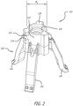
- the valve holder 110 can comprise a cap 118 coupled to a first end 114 of the shaft 112 and an engagement structure 120 coupled to a second end of the shaft 112.
- the cap 118 can comprise a bore with internal threads 124
- the shaft 112 can have a shaft width W 1 and a substantially circular-cross-section
- the engagement structure 120 can be configured to removably couple to the bioprosthetic heart valve 10.
- the engagement structure 120 illustrated in Figure 2 comprises a plurality of legs 122 that are outwardly and downwardly angled. The legs 122 can be arranged to contact and engage cusp regions of the heart valve 10, as is known in the art.
- one configuration for connecting the legs 122 to the heart valve 10 includes attachment sutures that loop through suture-permeable material in the heart valve 10 and tie off on the valve holder 110.
- a surgeon can manipulate a handle (not shown) screwed into the threaded bore 124 and advance the heart valve 10 into implant position. Once in position, the surgeon can sever the attachment sutures coupling the valve holder 110 to the heart valve 10, and remove the valve holder 110 and the handle.
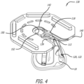
- the clip 130 can comprise a substantially planar body 132 having an outer periphery 134 and opposing inner edges 136A, 136B.
- the opposing inner edges 136A, 136B can define a slot 138 in the body 132 for receiving the shaft 112 of the valve holder 110.
- the slot 138 can be open at a first end 140 of the body 132 and can extend, along a longitudinal axis l of the body 132, from the first end 140 to a docking aperture 142.
- the present invention overcomes the challenges associated with the valve holder 110 becoming stuck or difficult to remove from the clip 130 as a result of the interference fit by incorporating a compliance feature 152 in the interreference-fit area 150.
- the compliance feature 152 can comprise a cutout 154A, 154B adjacent to at least one of the opposing inner edges 136A, 136B such that the at least one of the opposing inner edges 136A, 136B defines a beam 156A, 156B within the interference-fit area 150.
- the compliance feature 152 includes a cutout 154A, 154B adjacent each of the opposing inner edges 136A, 136B such that each of the opposing inner edges 136A, 136B defines a beam 156A, 156B within the interference-fit area 150.
- the compliance feature 152 allows the beams 156A, 156B to deform (as illustrated by the phantom beam in Figures 3E and 3F ), which reduces the force needed to push the shaft 112 of the valve holder 110 past the interference-fit area 150, and increases the tolerance range of the interference width for a given range of interference forces.
- the clip 130 can comprise a molded polymer, such as a high-density polyethylene or an acetal resin or a polyoxymethylene, such as DELRIN ® (manufactured by Dupont).
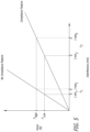
- the graph in Figure 5 illustrates the impact that a compliance feature 152 can have on the relationship between the interference force and the interference width.
- the slope for a clip having no compliance feature is steep; and the range ⁇ 1 between a minimum interference width I min1 and a maximum interference width I max1 -to produce a desired range of acceptable forces between F Low and F High -is small.
- the compliance feature 152 reduces the slope and increases the range ⁇ 2 between the minimum interference width I min2 and the maximum interference width I max2 -to produce the same desired range of acceptable forces between F Low and F High .
- the sub-assembly 100 can be placed into a container for further processing, storage, and transportation.
- the sub-assembly 100 can be used with a bioprosthetic heart valve 10 that is stored in a preservative solution, such as glutaraldehyde.
- the sub-assembly 100 can be configured to fit closely within a fluid-tight shipping jar, which is filled with preserving solution and sealed with a suitable lid, as described, for example, by U.S. Patent No. 9,295,539 .
- the sub-assembly 100 can be used with a dehydrated or dry bioprosthetic heart valve 10 that is stored in dry packaging, as described, for example, by U.S. Patent No. 9,539,080 .
- the clip 130 is depicted as an irregular hexagon, it should be understood that the clip 130 can be molded or otherwise formed to have a periphery that is round, square, rectangular, or any shape that is appropriate for a desired container.
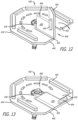
- a gas-permeable lid 300 having an outer band of adhesive (not shown) can be sealed over the upper surface 230 of the storage tray 200.
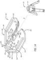
- FIG. 8-10 another embodiment of a clip 330 is provided that can be used with the valve holder 110 and storage tray 200 in a manner similar to the one depicted and described in relation to Figures 1 , 4 , 6 and 7 . Similar to the embodiment of the clip 130 depicted in Figures 1 , 4 , 6 , and 7 , the clip 330 can retain the shaft 112 of the valve holder 110 by way of an interference fit.
- the clip 330 can comprise a body 332 having an outer periphery 334 and opposing inner edges 336A, 336B.
- the body 332 can be substantially planar and the opposing inner edges 336A, 336B can define a passageway 338 in the body 332 for receiving the shaft 112 of the valve holder 110.
- the passageway 338 can be open at a first end 340 of the body 332 and can extend along a longitudinal axis l of the body 332 from the first end 340 to a terminal docking end 342.
- One or both of the terminal docking end 342 and the passageway 338 can also comprise a stepped ledge 339 onto which a first end 114 of the shaft 112 can rest. As depicted in Figure 2 , a portion of the first end 114 of the shaft 112 protrudes radially outwardly of the shaft 112 such that it can rest on top of the stepped ledge 339.
- the passageway 338 can include an interference-fit area 350 adjacent to the terminal docking end 342.
- the interference-fit area 350 can be the same or similar to the one described in relation to Figures 1 , 3 , 4 , 6 , and 7 or can simply be a narrowed area.
- a passageway width W 2 between the opposing inner edges 336A, 336B of the body 332 can decrease from the first end 340 of the body 332 to the interference-fit area 350.
- the passageway width W 2 of the interference-fit area 350 can be narrower than the valve holder's 110 shaft width W 1 .
- the interference width which is the difference between the shaft width W 1 and the passageway width W 2 of the interference-fit area 350 can be in the range of about 5 ⁇ m or more, about 10 ⁇ m or more, about 15 ⁇ m or more, about 20 ⁇ m or more, about 25 ⁇ m or more, about 30 ⁇ m or more, about 35 ⁇ m or more, about 40 ⁇ m or more, about 45 ⁇ m or more, about 50 ⁇ m or more, about 55 ⁇ m or more, about 60 ⁇ m or more, about 65 ⁇ m or more, about 70 ⁇ m or more, about 75 ⁇ m or more, about 80 ⁇ m or more, about 85 ⁇ m or more, about 90 ⁇ m or more, about 95 ⁇ m or more, about 100 ⁇ m or more, about 105 ⁇ m or more, about 110 ⁇ m or more, about 115 ⁇ m or more, about 120 ⁇ m or more, or about 125 ⁇ m or more.
- the interference width can also be in a range including and within
- the clip 330 can include a release mechanism which can increase the distance between the opposing inner edges 336A, 336B or increase the passageway width W 2 of the interference-fit area 350 to allow easy insertion and removal of the valve holder 110 into and from the terminal docking end 342.
- the release mechanism can be effectuated by a pinch-to-release mechanism as depicted in Figures 9 and 10 .
- the pinch-to-release mechanism can comprise one or more slots 380 having open ends disposed from a second end 341 of the body 332 and extending substantially towards the terminal docking end 342. In the embodiment depicted in Figures 8-10 , the first 340 and second 341 ends are opposing edges of the body 332 of the clip 330.
- the two slots 380 can extend at an angle from the open ends 381 and towards the terminal docking end 342.
- the distance d 1 between open ends 381 of the slots 380 can be greater than the distance d 2 between the slot ends 382.
- the one or more slots 380 can have the same width or varying widths. While the embodiment in Figures 8-10 depicts a pair of slots as having substantially the same width W 3 , it is understood that an embodiment can also comprise a single slot or two or more slots having the same or varying widths.
- the one or more slots 380 can be provided between a pair of holds 390 provided at the peripheral edges 343 of the body 332.
- the peripheral edge 343 can extend between the first 340 and second 341 ends of the body 332 in a straight line or in a curved and contoured shape as depicted in Figures 8-10 .
- the holds 390 can be pinched together to decrease the widths W 3 of the one or more slots 390 (see Figure 9 ) which, in turn, can increase the passageway width W 2 to facilitate easy insertion and removal of the valve holder's shaft 112 into and out of the terminal docking end 342 with less force.
- the widths W 3 of the one or more slots 380 may be decreased more substantially at the open ends 380 than at the area near the slot ends 382 when the holds 390 are compressed together.
- the force required to slidably move the valve holder 110 from the terminal docking end 342 and through passageway 338 to remove it from the clip 330 is less than 10N, less than 9N, less than 8N, less than 7N, less than 6N, less than 5N, less than 4N, less than 3N, less than 2N, or less than 1N.
- the one or more slots 380 can provide for a more secure fixation of the valve holder 110 and a larger dimensional tolerance.
- the interference-fit area 350 is provided to maintain the valve holder 110 within the terminal docking end 342 during processing, storage, and shipment-until the valve holder 110 is deliberately removed by the physician.
- the interference-fit area 350 should maintain the valve holder 110 in the terminal docking end 342 during transportation, and also allow for the easy removal of the valve holder 110 in the operating theater.
- the interference-fit area may be provided in a manner depicted and described with reference to Figures 1-7 .
- a clip 530 can be used with the valve holder 110 and storage tray 200 in a manner similar to the ones depicted and described in relation to Figures 1 , 6 , 7 , and 8-10 .
- the clip 530 can retain the shaft 112 of the valve holder 110 by way of an interference fit.
- the clip 530 can comprise a body 532 having an outer periphery 534 and opposing inner edges 536A, 536B.
- the body 532 can be substantially planar and the opposing inner edges 536A, 536B can define a passageway 538 in the body 532 for receiving the shaft 112 of the valve holder 110.
- the passageway 538 can be open at a first end 540 of the body 532 and can extend along a longitudinal axis l of the body 532 from the first end 540 to a terminal docking end 542.
- One or both of the terminal docking end 542 and the passageway 538 can also comprise a stepped ledge 539 onto which a first end 114 of the shaft 112 can rest. As depicted in Figure 2 , a portion of the first end 114 of the shaft 112 protrudes radially outwardly of the shaft 112 such that it can rest on top of the stepped ledge 539.
- the passageway 538 can include an interference-fit area 550 adjacent to the terminal docking end 542.
- the interference-fit area 550 can be the same or similar to the one described in relation to Figures 1 , 3 , 4 , 6 , 7 , and 8-10 or can simply be a narrowed area.
- a passageway width W 2 between the opposing inner edges 536A, 536B of the body 532 can decrease from the first end 540 of the body 532 to the interference-fit area 550.
- the passageway width W 2 in the interference-fit area 550 can be narrower than the valve holder's 110 shaft width W 1 .
- the interference width which is the difference between the shaft width W 1 and the passageway width W 2 of the interference-fit area 550 can be in the range of about 5 ⁇ m or more, about 10 ⁇ m or more, about 15 ⁇ m or more, about 20 ⁇ m or more, about 25 ⁇ m or more, about 30 ⁇ m or more, about 35 ⁇ m or more, about 40 ⁇ m or more, about 45 ⁇ m or more, about 50 ⁇ m or more, about 55 ⁇ m or more, about 60 ⁇ m or more, about 65 ⁇ m or more, about 70 ⁇ m or more, about 75 ⁇ m or more, about 80 ⁇ m or more, about 85 ⁇ m or more, about 90 ⁇ m or more, about 95 ⁇ m or more, about 100 ⁇ m or more, about 105 ⁇ m or more, about 110 ⁇ m or more, about 115 ⁇ m or more, about 120 ⁇ m or more, or about 125 ⁇ m or more.
- the interference width can also be in a range including and
- the clip 530 can include a release mechanism which can increase the distance between opposing inner edges 536A, 536B to allow easy insertion and removal of the valve holder 110 into and from the terminal docking end 542.
- the release mechanism can be effectuated by a pinch-to-release mechanism similar to the one depicted in Figures 9 and 10 .
- the pinch-to-release mechanism can comprise one or more slots 580 having open ends disposed from a second end 541 of the body 532 and extending substantially towards the terminal docking end 542.
- the first 540 and second 541 ends are opposing edges of the body 532 of the clip 530.
- the one or more slots 580 can have the same width or varying widths. While the embodiment in Figures 14-15 depicts a pair of slots as having substantially the same width W 3 , it is understood that an embodiment can also comprise a single slot or two or more slots having the same or varying widths.
- the one or more slots 580 can be provided between a pair of holds 590 provided on the body 532.
- the force required to slidably move the valve holder 110 from the terminal docking end 541 and through passageway 538 to remove it from the clip 530 is less than 10N, less than 9N, less than 8N, less than 7N, less than 6N, less than 5N, less than 4N, less than 3N, less than 2N, or less than 1N.
- the one or more slots 580 can provide for a more secure fixation of the valve holder 110 and a larger dimensional tolerance.
- the clip 530 can further include a plurality of openings 560 disposed within the body 532 to further decrease the force required to slidably move the valve holder 110 from the terminal docking end 542 and through passageway 538 to remove it from the clip 530.
- the plurality of openings 560 can be formed in any number of shapes (e.g. circular, oval, ovaline, rectilinear) and can be arranged in a variety of ways. In the embodiment depicted in Figures 1 , 3 , 4 , 6 , 7 , 14 and 15 , the plurality of openings is arranged around the terminal docking end 542. In alternative embodiments, the plurality of openings 560 can be arranged on one or both sides of the terminal docking end 542.
- the interference-fit area 550 is provided to maintain the valve holder 110 within the terminal docking end 542 during processing, storage, and shipment-until the valve holder 110 is deliberately removed by the physician.
- the interference-fit area 550 should maintain the valve holder 110 in the terminal docking end 542 during transportation, and also allow for the easy removal of the valve holder 110 in the operating theater.
- the interference-fit area may be provided in a manner depicted and described with reference to Figures 1-7 and 8-10 .
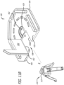
- the clip 430 can comprise a body 432 having an outer periphery 434 and opposing inner edges 436A, 436B.
- the body 432 can be substantially planar and the opposing inner edges 436A, 436B can define a passageway 438 in the body 432 for receiving the shaft 112 of the valve holder 110.
- the passageway 438 can be open at a first end 440 of the body 432 and can extend along a longitudinal axis l of the body 432 from the first end 440 to a terminal docking end 442.
- One or both of the terminal docking end 442 and the passageway 438 can optionally also comprise a stepped ledge 439, as depicted in FIG. 11C , onto which a first end 114 of the shaft 112 can rest. As depicted in Figure 2 , a portion of the first end 114 of the shaft 112 protrudes radially outwardly of the shaft 112.
- the flap 450 can be sized and shaped to cover or block at least a portion of the passageway 438 so as to secure the shaft 112 of the valve holder 110 at the terminal docking end 442 and prevent the shaft 112 from sliding out of the terminal docking end 442.
- the flap 450 can be sized to rest on top of the stepped ledge 439 shown in FIG. 11C to prevent it ffrom over rotating or falling below the body 432.
- the flap 450 can be shaped to include a stepped-in portion 460 covering a portion of the passageway 438 and a stepped-out portion 462 that conforms to at least a portion of the outer periphery 434.
- the shaft 112 of the valve holder 110 can be retained within the terminal docking end without requiring an interference fit.
- the widths of either or both of the terminal docking end 442 and the passageway 438 need not be less than the valve holder's 100 shaft width W 1 .
- the widths of one or both of the passageway 438 or terminal docking end 442 is roughly equal to or slightly greater than the width of the shaft 112 of the valve holder 110. As such, minimal to no force would be required move the valve holder 110 through the passageway 438 and into or out of the terminal docking end 442.
- the force required to move the valve holder 110 through the passageway 438 and into the terminal docking end 442 can be 5N or less, 4N or less, 3N or less, 2N or less, or 1N or less.
- the present invention provides an improved packaging assembly that provides an interference force within a desired range over a larger range of interference widths, thereby securely maintaining a bioprosthetic heart valve within the packaging system, while also allowing easy removal of the heart valve from the packaging system without damage or contamination.
- the terms “a,” “an,” and “at least one” encompass one or more of the specified element. That is, if two of a particular element are present, one of these elements is also present and thus “an” element is present.
- the terms “a plurality of” and “plural” mean two or more of the specified element.
- the term “or” used between the last two of a list of elements means any one or more of the listed elements. For example, the phrase “A, B, or C” means “A, B, and/or C,” which means “A,” “B,” “C,” “A and B,” “A and C,” “B and C,” or “A, B, and C.”
- the term “coupled” generally means physically coupled or linked and does not exclude the presence of intermediate elements between the coupled items absent specific contrary language.
Landscapes
- Health & Medical Sciences (AREA)
- Cardiology (AREA)
- Engineering & Computer Science (AREA)
- Biomedical Technology (AREA)
- Life Sciences & Earth Sciences (AREA)
- Transplantation (AREA)
- Heart & Thoracic Surgery (AREA)
- Vascular Medicine (AREA)
- Oral & Maxillofacial Surgery (AREA)
- Animal Behavior & Ethology (AREA)
- General Health & Medical Sciences (AREA)
- Public Health (AREA)
- Veterinary Medicine (AREA)
- Prostheses (AREA)
- Packages (AREA)
- Infusion, Injection, And Reservoir Apparatuses (AREA)
Claims (15)
- Verpackungsanordnung (1000) zum Aufbewahren einer bioprothetischen Herzklappe (10), wobei die Verpackungsanordnung (1000) umfasst:
eine Sub-Anordnung (100), die einen Klappenhalter (110) umfasst, der dazu konfiguriert ist, die bioprothetische Herzklappe (10) zu halten, und einen Clip (130), der dazu konfiguriert ist, einen Schaft (112) des Klappenhalters (110) aufzunehmen, wobei der Schaft (112) eine Schaftbreite aufweist, wobei der Clip (130) umfasst:einen Körper (132) mit einem Außenumfang (134) und gegenüberliegenden Innenkanten (136A, 136B), wobei die gegenüberliegenden Innenkanten (136A, 136B) einen Schlitz (138) in dem Körper (132) zur Aufnahme des Schafts (112) des Klappenhalters (110) definieren, wobei der Schlitz (138) an einem ersten Ende (140) des Körpers (132) offen ist und sich entlang einer Längsachse (I) des Körpers (132) von dem ersten Ende (140) zu einer Andocköffnung (142) erstreckt; undein Nachgiebigkeitsmerkmal (152) in einem Presspassungsbereich (150) des Schlitzes (138) neben der Andocköffnung (142);wobei eine Schlitzbreite (W2) zwischen den gegenüberliegenden Innenkanten (136A, 136B) des Körpers im Presspassungsbereich (150) kleiner ist als die Breite des Schafts, undwobei das Nachgiebigkeitsmerkmal (152) einen Ausschnitt (154A, 154B) benachbart zu jeder der gegenüberliegenden Innenkanten (136A, 136B) umfasst, so dass jede der gegenüberliegenden Innenkanten (136A, 136B) einen Balken (156A, 156B) innerhalb des Presspassungsbereichs (150) definiert,dadurch gekennzeichnet, dass das Nachgiebigkeitsmerkmal (152) dem Balken erlaubt, sich so zu verformen, dass die Kraft, die erforderlich ist, um den Schaft (112) des Klappenhalters (110) über den Presspassungsbereich (150) hinaus zu schieben, reduziert wird. - Verpackungsanordnung (1000) nach Anspruch 1, wobei der Körper (132) im Wesentlichen planar ist.
- Verpackungsanordnung (1000) nach einem der vorangehenden Ansprüche, wobei der durch jede der gegenüberliegenden Innenkanten (136A, 136B) definierte Balken (156A, 156B) ein fester Balken, ein freitragender Balken oder ein zweifach gestützter Balken ist.
- Verpackungsanordnung (1000) nach einem der vorangehenden Ansprüche, wobei der Ausschnitt (154A, 154B) neben jeder der gegenüberliegenden Innenkanten (136A, 136B) länglich ist.
- Verpackungsanordnung (1000) nach einem der vorangehenden Ansprüche, wobei der durch jede der gegenüberliegenden Innenkanten (136A, 136B) definierte Balken (156A, 156B) eine durchschnittliche Balkenbreite (W3) von etwa 0,5 mm bis etwa 2 mm aufweist.
- Verpackungsanordnung (1000) nach einem der vorangehenden Ansprüche, wobei die Schlitzbreite (W2) vom ersten Ende (140) des Körpers (132) bis zum Presspassungsbereich (150) abnimmt.
- Verpackungsanordnung (1000) nach einem der vorangehenden Ansprüche, wobei der Clip (130) ein geformtes Polymer umfasst.
- Verpackungsanordnung (1000) nach einem der vorangehenden Ansprüche, wobei der Clip (130) ein hochdichtes Polyethylen oder ein Acetalharz umfasst.
- Verpackungsanordnung (1000) nach einem der vorangehenden Ansprüche, wobei der Klappenhalter (110) ferner eine Kappe (118), die mit einem ersten Ende (114) des Schafts (112) gekoppelt ist, und eine Eingriffsstruktur (120) umfasst, die mit einem zweiten Ende des Schafts (112) gekoppelt ist, wobei die Eingriffsstruktur (120) dazu konfiguriert ist, lösbar an die bioprothetische Herzklappe (10) anzukoppeln.
- Verpackungsanordnung (1000) nach Anspruch 9, wobei der Schaft (112) die Kappe (118) und die Eingriffsstruktur (120) trennt.
- Verpackungsanordnung (1000) nach Anspruch 9 oder 10, wobei die Eingriffsstruktur (120) mehrere Schenkel (122) umfasst.
- Verpackungsanordnung (1000) nach Anspruch 11, wobei die mehreren Schenkel (122) nach außen und nach unten angewinkelt sind.
- Verpackungsanordnung (1000) nach einem der vorangehenden Ansprüche, die ferner eine Aufbewahrungsschale (200) umfasst, die einen gestuften Absatz (210) aufweist, der einen Hohlraum (220) umgibt.
- Verpackungsanordnung (1000) nach Anspruch 13, wobei der Körper (132) des Clips so geformt ist, dass er auf dem gestuften Absatz (210) der Aufbewahrungsschale (200) ruht, so dass die Eingriffsstruktur (120) des Klappenhalters innerhalb des Hohlraums (220) der Aufbewahrungsschale (200) aufgehängt ist, wenn der Klappenhalter (110) innerhalb der Andocköffnung (142) des Clips angedockt ist.
- Verpackungsanordnung (1000) nach Anspruch 13 oder 14, ferner einen gasdurchlässigen Deckel (300) umfassend, der mit einer oberen Oberfläche (230) der Aufbewahrungsschale (200) verbunden ist.
Priority Applications (1)
| Application Number | Priority Date | Filing Date | Title |
|---|---|---|---|
| EP25182390.2A EP4591834A3 (de) | 2019-08-02 | 2020-08-03 | Prothetische herzklappenverpackung |
Applications Claiming Priority (2)
| Application Number | Priority Date | Filing Date | Title |
|---|---|---|---|
| US201962882415P | 2019-08-02 | 2019-08-02 | |
| PCT/US2020/044701 WO2021026051A1 (en) | 2019-08-02 | 2020-08-03 | Prosthetic heart valve packaging |
Related Child Applications (1)
| Application Number | Title | Priority Date | Filing Date |
|---|---|---|---|
| EP25182390.2A Division EP4591834A3 (de) | 2019-08-02 | 2020-08-03 | Prothetische herzklappenverpackung |
Publications (2)
| Publication Number | Publication Date |
|---|---|
| EP4007544A1 EP4007544A1 (de) | 2022-06-08 |
| EP4007544B1 true EP4007544B1 (de) | 2025-07-09 |
Family
ID=72243190
Family Applications (2)
| Application Number | Title | Priority Date | Filing Date |
|---|---|---|---|
| EP20761929.7A Active EP4007544B1 (de) | 2019-08-02 | 2020-08-03 | Verpackung einer herzklappenprothese |
| EP25182390.2A Pending EP4591834A3 (de) | 2019-08-02 | 2020-08-03 | Prothetische herzklappenverpackung |
Family Applications After (1)
| Application Number | Title | Priority Date | Filing Date |
|---|---|---|---|
| EP25182390.2A Pending EP4591834A3 (de) | 2019-08-02 | 2020-08-03 | Prothetische herzklappenverpackung |
Country Status (5)
| Country | Link |
|---|---|
| US (2) | US12239522B2 (de) |
| EP (2) | EP4007544B1 (de) |
| CN (2) | CN215349734U (de) |
| CA (1) | CA3142788A1 (de) |
| WO (1) | WO2021026051A1 (de) |
Families Citing this family (3)
| Publication number | Priority date | Publication date | Assignee | Title |
|---|---|---|---|---|
| US20160361150A1 (en) * | 2015-06-12 | 2016-12-15 | Natural Dental Implants Ag | Systems and methods for sterile delivery of prostheses |
| EP4007544B1 (de) * | 2019-08-02 | 2025-07-09 | Edwards Lifesciences Corporation | Verpackung einer herzklappenprothese |
| USD1106488S1 (en) * | 2022-09-12 | 2025-12-16 | Edwards Lifesciences Corporation | Dry packaging for heart valve |
Citations (7)
| Publication number | Priority date | Publication date | Assignee | Title |
|---|---|---|---|---|
| US5560487A (en) * | 1994-07-29 | 1996-10-01 | Carbomedics, Inc. | Holder and packaging for bioprosthetic heart valve |
| WO2000040176A1 (en) * | 1998-12-30 | 2000-07-13 | St. Jude Medical, Inc. | Tissue heart valve holder |
| US20080262603A1 (en) * | 2007-04-23 | 2008-10-23 | Sorin Biomedica Cardio | Prosthetic heart valve holder |
| EP1985259A1 (de) * | 2007-04-23 | 2008-10-29 | Sorin Biomedica Cardio S.R.L. | Prothetischer Herzklappenhalter |
| US20110147251A1 (en) * | 2009-12-18 | 2011-06-23 | Edwards Lifesciences Corporation | Prosthetic heart valve packaging and deployment system |
| US20120046738A1 (en) * | 2010-08-23 | 2012-02-23 | Edwards Lifesciences Corporation | Color-Coded Prosthetic Valve System and Methods for Using the Same |
| US20120290079A1 (en) * | 2011-05-12 | 2012-11-15 | Edwards Lifesciences Corporation | Mitral heart valve holder and storage system |
Family Cites Families (53)
| Publication number | Priority date | Publication date | Assignee | Title |
|---|---|---|---|---|
| US4011947A (en) | 1975-05-22 | 1977-03-15 | Philip Nicholas Sawyer | Packaged prosthetic device |
| US4101031A (en) | 1975-10-06 | 1978-07-18 | Medical Engineering Corp. | Package for prosthetic heart valve or the like |
| US4182446A (en) | 1978-06-12 | 1980-01-08 | Hancock Laboratories, Inc. | Heart valve holder |
| US4211325A (en) | 1979-06-07 | 1980-07-08 | Hancock Laboratories, Inc. | Heart valve holder |
| US4801015A (en) | 1986-04-16 | 1989-01-31 | Shiley Inc. | Releasable holder and package assembly for a prosthetic heart valve |
| US4697703A (en) | 1986-07-02 | 1987-10-06 | Malcolm Will | Joint prosthesis package |
| US5167223A (en) | 1989-09-08 | 1992-12-01 | Tibor Koros | Heart valve retractor and sternum spreader surgical instrument |
| US5336616A (en) | 1990-09-12 | 1994-08-09 | Lifecell Corporation | Method for processing and preserving collagen-based tissues for transplantation |
| US5236450A (en) | 1992-06-04 | 1993-08-17 | Carbon Implants, Inc. | Heart valve holder-rotator |
| US5531785A (en) | 1994-05-06 | 1996-07-02 | Autogenics, Inc. | Prosthetic heart valve holder |
| US5480425A (en) | 1994-06-09 | 1996-01-02 | Carbomedics, Inc. | Integrated heart valve rotator and holder |
| US5582607A (en) | 1994-09-09 | 1996-12-10 | Carbomedics, Inc. | Heart valve prosthesis rotator with bendable shaft and drive mechanism |
| US5776187A (en) | 1995-02-09 | 1998-07-07 | St. Jude Medical, Inc. | Combined holder tool and rotator for a prosthetic heart valve |
| US5578076A (en) | 1995-05-24 | 1996-11-26 | St. Jude Medical, Inc. | Low profile holder for heart valve prosthesis |
| US5615770A (en) | 1995-08-10 | 1997-04-01 | Smith & Nephew, Inc. | Implant package insert delivery system |
| US5720391A (en) * | 1996-03-29 | 1998-02-24 | St. Jude Medical, Inc. | Packaging and holder for heart valve prosthesis |
| US5868253A (en) * | 1996-03-29 | 1999-02-09 | St. Jude Medical, Inc. | Hinged support collar for mechanical heart valve packaging |
| US5690226A (en) | 1996-04-19 | 1997-11-25 | Benoist Girard | Air-impermeable packaging for medical implants |
| US5800531A (en) * | 1996-09-30 | 1998-09-01 | Baxter International Inc. | Bioprosthetic heart valve implantation device |
| US5984959A (en) | 1997-09-19 | 1999-11-16 | United States Surgical | Heart valve replacement tools and procedures |
| US5980569A (en) | 1997-09-19 | 1999-11-09 | United States Surgical Corp. | Prosthetic valve holder and method of use |
| US5823342A (en) | 1997-11-14 | 1998-10-20 | Sulzer Carbomedics Inc. | Packaging for mitral or aortic heart valve device |
| US6090138A (en) | 1998-01-23 | 2000-07-18 | Sulzer Carbomedics Inc. | Universal heart valve holder |
| CA2335152C (en) | 1998-05-14 | 2008-11-18 | The Cleveland Clinic Foundation | Processing of implantable animal tissues for dry storage |
| US6346094B2 (en) | 1998-09-28 | 2002-02-12 | Becton, Dickinson And Company | Pen needle magazine |
| US6736845B2 (en) | 1999-01-26 | 2004-05-18 | Edwards Lifesciences Corporation | Holder for flexible heart valve |
| US6199696B1 (en) | 1999-05-26 | 2001-03-13 | Sulzer Carbomedics Inc. | Shock resistant packaging for a prosthetic heart valve |
| US6416547B1 (en) * | 1999-10-06 | 2002-07-09 | Edwards Lifesciences Corporation | Heart valve carrier and rinse cage |
| US6543610B1 (en) | 2000-09-12 | 2003-04-08 | Alok Nigam | System for packaging and handling an implant and method of use |
| US20020120328A1 (en) | 2000-12-21 | 2002-08-29 | Pathak Chandrashekhar Prabhakar | Mechanical heart valve packaged in a liquid |
| US6591998B2 (en) | 2000-12-21 | 2003-07-15 | Sulzer Carbomedics Inc. | Leakproof container for implantable prosthetic device |
| US6966925B2 (en) | 2000-12-21 | 2005-11-22 | Edwards Lifesciences Corporation | Heart valve holder and method for resisting suture looping |
| US6723122B2 (en) | 2001-08-30 | 2004-04-20 | Edwards Lifesciences Corporation | Container and method for storing and delivering minimally-invasive heart valves |
| US6996952B2 (en) | 2003-09-30 | 2006-02-14 | Codman & Shurtleff, Inc. | Method for improving stability and effectivity of a drug-device combination product |
| JP2008506497A (ja) * | 2004-07-19 | 2008-03-06 | セント ジュード メディカル インコーポレイテッド | 心臓弁の支持体および蓋裏打ちシステムならびに方法 |
| EP1796693A2 (de) | 2004-08-26 | 2007-06-20 | Chandrashekhar P. Pathak | Implantierbare gewebezusammensetzungen und verfahren |
| US7699168B2 (en) * | 2004-10-29 | 2010-04-20 | Medtronic, Inc. | Heart valve storage and shipping retainer |
| US8287583B2 (en) | 2005-01-10 | 2012-10-16 | Taheri Laduca Llc | Apparatus and method for deploying an implantable device within the body |
| DK1850796T3 (en) | 2005-02-18 | 2016-01-18 | Cleveland Clinic Foundation | DEVICE FOR REPLACEMENT OF A HEART VALVE |
| US7712606B2 (en) | 2005-09-13 | 2010-05-11 | Sadra Medical, Inc. | Two-part package for medical implant |
| US8876895B2 (en) | 2006-09-19 | 2014-11-04 | Medtronic Ventor Technologies Ltd. | Valve fixation member having engagement arms |
| US7578842B2 (en) | 2006-10-03 | 2009-08-25 | St. Jude Medical, Inc. | Prosthetic heart valves |
| US7866468B2 (en) | 2007-01-12 | 2011-01-11 | George Kyritsis | Medical instrument sterilization pouch |
| US8105375B2 (en) | 2007-01-19 | 2012-01-31 | The Cleveland Clinic Foundation | Method for implanting a cardiovascular valve |
| DE102007015154A1 (de) * | 2007-03-22 | 2008-09-25 | Aesculap Ag & Co. Kg | Haltevorrichtung für ein Implantat |
| US8357387B2 (en) | 2007-12-21 | 2013-01-22 | Edwards Lifesciences Corporation | Capping bioprosthetic tissue to reduce calcification |
| US8839957B2 (en) | 2010-02-15 | 2014-09-23 | Michael C. Murad | Prosthetic heart valve packaging system |
| US8679404B2 (en) | 2010-03-05 | 2014-03-25 | Edwards Lifesciences Corporation | Dry prosthetic heart valve packaging system |
| US8652145B2 (en) | 2011-12-14 | 2014-02-18 | Edwards Lifesciences Corporation | System and method for crimping a prosthetic valve |
| US9301835B2 (en) | 2012-06-04 | 2016-04-05 | Edwards Lifesciences Corporation | Pre-assembled bioprosthetic valve and sealed conduit |
| EP3213718B1 (de) * | 2014-09-24 | 2019-06-26 | Sorin Group Italia S.r.l. | Halter für herzklappenprothesen, entsprechende lageranordnung, freisetzungsinstrument und kit |
| US10350047B2 (en) | 2015-09-02 | 2019-07-16 | Edwards Lifesciences Corporation | Method and system for packaging and preparing a prosthetic heart valve and associated delivery system |
| EP4007544B1 (de) * | 2019-08-02 | 2025-07-09 | Edwards Lifesciences Corporation | Verpackung einer herzklappenprothese |
-
2020
- 2020-08-03 EP EP20761929.7A patent/EP4007544B1/de active Active
- 2020-08-03 EP EP25182390.2A patent/EP4591834A3/de active Pending
- 2020-08-03 WO PCT/US2020/044701 patent/WO2021026051A1/en not_active Ceased
- 2020-08-03 CA CA3142788A patent/CA3142788A1/en active Pending
- 2020-08-03 CN CN202021585669.9U patent/CN215349734U/zh active Active
- 2020-08-03 CN CN202080045713.3A patent/CN114007551B/zh active Active
-
2022
- 2022-01-31 US US17/649,532 patent/US12239522B2/en active Active
-
2025
- 2025-02-07 US US19/048,515 patent/US20250177111A1/en active Pending
Patent Citations (7)
| Publication number | Priority date | Publication date | Assignee | Title |
|---|---|---|---|---|
| US5560487A (en) * | 1994-07-29 | 1996-10-01 | Carbomedics, Inc. | Holder and packaging for bioprosthetic heart valve |
| WO2000040176A1 (en) * | 1998-12-30 | 2000-07-13 | St. Jude Medical, Inc. | Tissue heart valve holder |
| US20080262603A1 (en) * | 2007-04-23 | 2008-10-23 | Sorin Biomedica Cardio | Prosthetic heart valve holder |
| EP1985259A1 (de) * | 2007-04-23 | 2008-10-29 | Sorin Biomedica Cardio S.R.L. | Prothetischer Herzklappenhalter |
| US20110147251A1 (en) * | 2009-12-18 | 2011-06-23 | Edwards Lifesciences Corporation | Prosthetic heart valve packaging and deployment system |
| US20120046738A1 (en) * | 2010-08-23 | 2012-02-23 | Edwards Lifesciences Corporation | Color-Coded Prosthetic Valve System and Methods for Using the Same |
| US20120290079A1 (en) * | 2011-05-12 | 2012-11-15 | Edwards Lifesciences Corporation | Mitral heart valve holder and storage system |
Also Published As
| Publication number | Publication date |
|---|---|
| US20250177111A1 (en) | 2025-06-05 |
| EP4007544A1 (de) | 2022-06-08 |
| CN114007551A (zh) | 2022-02-01 |
| CN215349734U (zh) | 2021-12-31 |
| CA3142788A1 (en) | 2021-02-11 |
| US20220151759A1 (en) | 2022-05-19 |
| CN114007551B (zh) | 2025-10-17 |
| US12239522B2 (en) | 2025-03-04 |
| EP4591834A2 (de) | 2025-07-30 |
| EP4591834A3 (de) | 2025-10-08 |
| WO2021026051A1 (en) | 2021-02-11 |
Similar Documents
| Publication | Publication Date | Title |
|---|---|---|
| US20250177111A1 (en) | Prosthetic heart valve packaging | |
| US6126007A (en) | Tissue valve holder | |
| US10064694B2 (en) | Locking mechanism for a medical device assembly tray | |
| US5720391A (en) | Packaging and holder for heart valve prosthesis | |
| EP2536345B1 (de) | Packsystem für eine künstliche herzklappe | |
| US7648030B2 (en) | Medical packaging | |
| US5281227A (en) | Lens case with IOL folding device | |
| US5776187A (en) | Combined holder tool and rotator for a prosthetic heart valve | |
| EP1720490B1 (de) | Vorrichtungen zur aufbewahrung, ladung und abgabe einer intraokularlinse | |
| US6591998B2 (en) | Leakproof container for implantable prosthetic device | |
| US6976584B2 (en) | Package for surgical implant | |
| EP1874242A2 (de) | Hornhautimplantat-injektoranordnung und anwendungsverfahren | |
| US12472050B2 (en) | Dock holder, packaging, and methods of use | |
| CN114590487B (zh) | 植入体包装容器及植入体包装组合物 | |
| KR102886828B1 (ko) | 임플란트 포장용 앰플 | |
| US12364587B2 (en) | Storage jar assembly for a prosthetic heart valve | |
| CN214734309U (zh) | 植入体包装组件 | |
| US20230225859A1 (en) | Intraocular lens delivery system |
Legal Events
| Date | Code | Title | Description |
|---|---|---|---|
| STAA | Information on the status of an ep patent application or granted ep patent |
Free format text: STATUS: UNKNOWN |
|
| STAA | Information on the status of an ep patent application or granted ep patent |
Free format text: STATUS: THE INTERNATIONAL PUBLICATION HAS BEEN MADE |
|
| PUAI | Public reference made under article 153(3) epc to a published international application that has entered the european phase |
Free format text: ORIGINAL CODE: 0009012 |
|
| STAA | Information on the status of an ep patent application or granted ep patent |
Free format text: STATUS: REQUEST FOR EXAMINATION WAS MADE |
|
| 17P | Request for examination filed |
Effective date: 20211217 |
|
| AK | Designated contracting states |
Kind code of ref document: A1 Designated state(s): AL AT BE BG CH CY CZ DE DK EE ES FI FR GB GR HR HU IE IS IT LI LT LU LV MC MK MT NL NO PL PT RO RS SE SI SK SM TR |
|
| DAV | Request for validation of the european patent (deleted) | ||
| DAX | Request for extension of the european patent (deleted) | ||
| P01 | Opt-out of the competence of the unified patent court (upc) registered |
Effective date: 20230922 |
|
| P02 | Opt-out of the competence of the unified patent court (upc) changed |
Effective date: 20230926 |
|
| GRAP | Despatch of communication of intention to grant a patent |
Free format text: ORIGINAL CODE: EPIDOSNIGR1 |
|
| STAA | Information on the status of an ep patent application or granted ep patent |
Free format text: STATUS: GRANT OF PATENT IS INTENDED |
|
| INTG | Intention to grant announced |
Effective date: 20240911 |
|
| RAP3 | Party data changed (applicant data changed or rights of an application transferred) |
Owner name: EDWARDS LIFESCIENCES CORPORATION |
|
| GRAJ | Information related to disapproval of communication of intention to grant by the applicant or resumption of examination proceedings by the epo deleted |
Free format text: ORIGINAL CODE: EPIDOSDIGR1 |
|
| STAA | Information on the status of an ep patent application or granted ep patent |
Free format text: STATUS: REQUEST FOR EXAMINATION WAS MADE |
|
| GRAP | Despatch of communication of intention to grant a patent |
Free format text: ORIGINAL CODE: EPIDOSNIGR1 |
|
| STAA | Information on the status of an ep patent application or granted ep patent |
Free format text: STATUS: GRANT OF PATENT IS INTENDED |
|
| INTC | Intention to grant announced (deleted) | ||
| INTG | Intention to grant announced |
Effective date: 20250130 |
|
| GRAS | Grant fee paid |
Free format text: ORIGINAL CODE: EPIDOSNIGR3 |
|
| GRAA | (expected) grant |
Free format text: ORIGINAL CODE: 0009210 |
|
| STAA | Information on the status of an ep patent application or granted ep patent |
Free format text: STATUS: THE PATENT HAS BEEN GRANTED |
|
| AK | Designated contracting states |
Kind code of ref document: B1 Designated state(s): AL AT BE BG CH CY CZ DE DK EE ES FI FR GB GR HR HU IE IS IT LI LT LU LV MC MK MT NL NO PL PT RO RS SE SI SK SM TR |
|
| REG | Reference to a national code |
Ref country code: GB Ref legal event code: FG4D |
|
| REG | Reference to a national code |
Ref country code: CH Ref legal event code: EP |
|
| REG | Reference to a national code |
Ref country code: IE Ref legal event code: FG4D |
|
| REG | Reference to a national code |
Ref country code: DE Ref legal event code: R096 Ref document number: 602020054217 Country of ref document: DE |
|
| PGFP | Annual fee paid to national office [announced via postgrant information from national office to epo] |
Ref country code: DE Payment date: 20250702 Year of fee payment: 6 |
|
| PGFP | Annual fee paid to national office [announced via postgrant information from national office to epo] |
Ref country code: GB Payment date: 20250729 Year of fee payment: 6 |
|
| REG | Reference to a national code |
Ref country code: NL Ref legal event code: MP Effective date: 20250709 |
|
| PG25 | Lapsed in a contracting state [announced via postgrant information from national office to epo] |
Ref country code: PT Free format text: LAPSE BECAUSE OF FAILURE TO SUBMIT A TRANSLATION OF THE DESCRIPTION OR TO PAY THE FEE WITHIN THE PRESCRIBED TIME-LIMIT Effective date: 20251110 |
|
| PG25 | Lapsed in a contracting state [announced via postgrant information from national office to epo] |
Ref country code: NL Free format text: LAPSE BECAUSE OF FAILURE TO SUBMIT A TRANSLATION OF THE DESCRIPTION OR TO PAY THE FEE WITHIN THE PRESCRIBED TIME-LIMIT Effective date: 20250709 |
|
| REG | Reference to a national code |
Ref country code: AT Ref legal event code: MK05 Ref document number: 1811114 Country of ref document: AT Kind code of ref document: T Effective date: 20250709 |
|
| PG25 | Lapsed in a contracting state [announced via postgrant information from national office to epo] |
Ref country code: IS Free format text: LAPSE BECAUSE OF FAILURE TO SUBMIT A TRANSLATION OF THE DESCRIPTION OR TO PAY THE FEE WITHIN THE PRESCRIBED TIME-LIMIT Effective date: 20251109 |
|
| PG25 | Lapsed in a contracting state [announced via postgrant information from national office to epo] |
Ref country code: NO Free format text: LAPSE BECAUSE OF FAILURE TO SUBMIT A TRANSLATION OF THE DESCRIPTION OR TO PAY THE FEE WITHIN THE PRESCRIBED TIME-LIMIT Effective date: 20251009 |
|
| REG | Reference to a national code |
Ref country code: LT Ref legal event code: MG9D |
|
| PG25 | Lapsed in a contracting state [announced via postgrant information from national office to epo] |
Ref country code: AT Free format text: LAPSE BECAUSE OF FAILURE TO SUBMIT A TRANSLATION OF THE DESCRIPTION OR TO PAY THE FEE WITHIN THE PRESCRIBED TIME-LIMIT Effective date: 20250709 |
|
| PG25 | Lapsed in a contracting state [announced via postgrant information from national office to epo] |
Ref country code: FI Free format text: LAPSE BECAUSE OF FAILURE TO SUBMIT A TRANSLATION OF THE DESCRIPTION OR TO PAY THE FEE WITHIN THE PRESCRIBED TIME-LIMIT Effective date: 20250709 |
|
| PG25 | Lapsed in a contracting state [announced via postgrant information from national office to epo] |
Ref country code: HR Free format text: LAPSE BECAUSE OF FAILURE TO SUBMIT A TRANSLATION OF THE DESCRIPTION OR TO PAY THE FEE WITHIN THE PRESCRIBED TIME-LIMIT Effective date: 20250709 |
|
| PG25 | Lapsed in a contracting state [announced via postgrant information from national office to epo] |
Ref country code: GR Free format text: LAPSE BECAUSE OF FAILURE TO SUBMIT A TRANSLATION OF THE DESCRIPTION OR TO PAY THE FEE WITHIN THE PRESCRIBED TIME-LIMIT Effective date: 20251010 |
|
| PG25 | Lapsed in a contracting state [announced via postgrant information from national office to epo] |
Ref country code: SE Free format text: LAPSE BECAUSE OF FAILURE TO SUBMIT A TRANSLATION OF THE DESCRIPTION OR TO PAY THE FEE WITHIN THE PRESCRIBED TIME-LIMIT Effective date: 20250709 |
|
| PG25 | Lapsed in a contracting state [announced via postgrant information from national office to epo] |
Ref country code: LV Free format text: LAPSE BECAUSE OF FAILURE TO SUBMIT A TRANSLATION OF THE DESCRIPTION OR TO PAY THE FEE WITHIN THE PRESCRIBED TIME-LIMIT Effective date: 20250709 |
|
| PG25 | Lapsed in a contracting state [announced via postgrant information from national office to epo] |
Ref country code: PL Free format text: LAPSE BECAUSE OF FAILURE TO SUBMIT A TRANSLATION OF THE DESCRIPTION OR TO PAY THE FEE WITHIN THE PRESCRIBED TIME-LIMIT Effective date: 20250709 Ref country code: BG Free format text: LAPSE BECAUSE OF FAILURE TO SUBMIT A TRANSLATION OF THE DESCRIPTION OR TO PAY THE FEE WITHIN THE PRESCRIBED TIME-LIMIT Effective date: 20250709 |
|
| PG25 | Lapsed in a contracting state [announced via postgrant information from national office to epo] |
Ref country code: RS Free format text: LAPSE BECAUSE OF FAILURE TO SUBMIT A TRANSLATION OF THE DESCRIPTION OR TO PAY THE FEE WITHIN THE PRESCRIBED TIME-LIMIT Effective date: 20251009 |
|
| PG25 | Lapsed in a contracting state [announced via postgrant information from national office to epo] |
Ref country code: ES Free format text: LAPSE BECAUSE OF FAILURE TO SUBMIT A TRANSLATION OF THE DESCRIPTION OR TO PAY THE FEE WITHIN THE PRESCRIBED TIME-LIMIT Effective date: 20250709 |