EP4007528B1 - Kardiale vorrichtung - Google Patents
Kardiale vorrichtung Download PDFInfo
- Publication number
- EP4007528B1 EP4007528B1 EP20756933.6A EP20756933A EP4007528B1 EP 4007528 B1 EP4007528 B1 EP 4007528B1 EP 20756933 A EP20756933 A EP 20756933A EP 4007528 B1 EP4007528 B1 EP 4007528B1
- Authority
- EP
- European Patent Office
- Prior art keywords
- probe
- cardiac
- cardiac device
- transmitter
- ventricular
- Prior art date
- Legal status (The legal status is an assumption and is not a legal conclusion. Google has not performed a legal analysis and makes no representation as to the accuracy of the status listed.)
- Active
Links
Images

Classifications
-
- A—HUMAN NECESSITIES
- A61—MEDICAL OR VETERINARY SCIENCE; HYGIENE
- A61B—DIAGNOSIS; SURGERY; IDENTIFICATION
- A61B8/00—Diagnosis using ultrasonic, sonic or infrasonic waves
- A61B8/08—Clinical applications
- A61B8/0883—Clinical applications for diagnosis of the heart
-
- A—HUMAN NECESSITIES
- A61—MEDICAL OR VETERINARY SCIENCE; HYGIENE
- A61B—DIAGNOSIS; SURGERY; IDENTIFICATION
- A61B8/00—Diagnosis using ultrasonic, sonic or infrasonic waves
- A61B8/48—Diagnostic techniques
- A61B8/485—Diagnostic techniques involving measuring strain or elastic properties
-
- A—HUMAN NECESSITIES
- A61—MEDICAL OR VETERINARY SCIENCE; HYGIENE
- A61B—DIAGNOSIS; SURGERY; IDENTIFICATION
- A61B8/00—Diagnosis using ultrasonic, sonic or infrasonic waves
- A61B8/52—Devices using data or image processing specially adapted for diagnosis using ultrasonic, sonic or infrasonic waves
- A61B8/5215—Devices using data or image processing specially adapted for diagnosis using ultrasonic, sonic or infrasonic waves involving processing of medical diagnostic data
- A61B8/5223—Devices using data or image processing specially adapted for diagnosis using ultrasonic, sonic or infrasonic waves involving processing of medical diagnostic data for extracting a diagnostic or physiological parameter from medical diagnostic data
-
- A—HUMAN NECESSITIES
- A61—MEDICAL OR VETERINARY SCIENCE; HYGIENE
- A61B—DIAGNOSIS; SURGERY; IDENTIFICATION
- A61B8/00—Diagnosis using ultrasonic, sonic or infrasonic waves
- A61B8/54—Control of the diagnostic device
- A61B8/543—Control of the diagnostic device involving acquisition triggered by a physiological signal
-
- G—PHYSICS
- G01—MEASURING; TESTING
- G01S—RADIO DIRECTION-FINDING; RADIO NAVIGATION; DETERMINING DISTANCE OR VELOCITY BY USE OF RADIO WAVES; LOCATING OR PRESENCE-DETECTING BY USE OF THE REFLECTION OR RERADIATION OF RADIO WAVES; ANALOGOUS ARRANGEMENTS USING OTHER WAVES
- G01S7/00—Details of systems according to groups G01S13/00, G01S15/00, G01S17/00
- G01S7/52—Details of systems according to groups G01S13/00, G01S15/00, G01S17/00 of systems according to group G01S15/00
- G01S7/52017—Details of systems according to groups G01S13/00, G01S15/00, G01S17/00 of systems according to group G01S15/00 particularly adapted to short-range imaging
- G01S7/52023—Details of receivers
- G01S7/52036—Details of receivers using analysis of echo signal for target characterisation
- G01S7/52042—Details of receivers using analysis of echo signal for target characterisation determining elastic properties of the propagation medium or of the reflective target
Definitions
- the present invention relates to the field of cardiac measurement, and more particularly to non-invasive cardiac measurement.
- Cardiac measurement covers measurements of physical quantities of a patient's heart, in particular mechanical parameters.
- the invention improves the situation.
- the invention proposes a cardiac device, comprising a transmitter arranged to emit at least one wave, a probe arranged to measure a shear wave caused by a wave from the transmitter, a detector arranged to detect a systole phase in an electrocardiographic signal, and an estimator arranged to determine, during at least one cardiac cycle, the propagation speed of a plurality of shear waves caused by the emission of waves in several directions towards the heart of a patient, to determine using the detector the one which has a maximum propagation speed during the systole phase, and to derive an active cardiac stress therefrom.
- This device is advantageous because it allows direct access to the active stress in the cardiac tissue.
- the active stress is a force per unit area.
- the intraventricular pressure can be derived from the active stress.
- Cardiac pathologies can also be detected from an active constraint measurement, and for example, the after-effects of a heart attack can be observed.
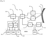
- a cardiac device 1 comprises a memory 2, a transmitter 10 and a probe 12.
- Memory 2 can be any type of data storage suitable for receiving digital data: hard disk, flash memory hard disk (SSD in English), flash memory in any form, random access memory, magnetic disk, locally or cloud distributed storage, etc.
- the data stored in the memory 2 may be erased after the cardiac device 1 has performed its tasks, or retained.
- the data calculated by the cardiac device may be stored on the memory 2 or on any type of memory similar to it.
- Non-invasive techniques for observing anisotropic (e.g. fibrous) media by ultrasound have been developed.
- the application PCT/FR2015/050058 focuses on the measurement of mechanical characteristics within anisotropic media, by observing the propagation of ultrasound within them.
- the transmitter 10 is here a device capable of emitting ultrasound.
- the cardiac device 1 also comprises a detector 14 and an estimator 16.
- the detector 14 determines the moments when the observed heart is in systole phase, that is to say when the heart contracts.
- the estimator 16 is connected to the transmitter 10, to the probe 12 and to the detector 14 so as to be able to receive the data coming therefrom.
- the estimator 16 can derive from this data one or more physical quantities, in particular an active constraint 160 of the cardiac tissue.
- the transmitter 10 and the probe 12 are placed in contact with the skin of a patient whose heart 6 is to be observed, and directed towards the latter.
- the transmitter 10 and the probe 12 operate in concert to observe the propagation of shear waves within cardiac tissues.
- the transmitter 10 generates a focused ultrasound beam for a short duration, in an emission direction towards the heart 6.
- This beam causes, when it reaches the heart, the displacement of the cardiac tissue 4 by the effect of acoustic radiation pressure.
- This displacement takes the form of a shear wave which propagates within the heart tissue 4 in a propagation direction substantially orthogonal to the emission direction.
- the probe 12 observes the propagation of the shear wave. To do this, the probe 12 emits ultrasound at high rates in the form of compression waves towards the heart 6. These ultrasounds are reverberated by the cardiac tissue 4 deforming under the effect of the shear wave. The reverberated waves are picked up by the probe 12, which makes it possible to observe the movement of the cardiac tissue 4.
- the rate at which the probe 12 emits ultrasounds is greater than 300 Hz, or even 500 Hz.
- Each individual shear wave propagation measurement can be carried out in approximately a few milliseconds. The probe 12 can thus observe with great precision and several hundred times per second the propagation of the shear wave within the cardiac tissue 4.
- the probe 12 also determines the propagation speed of the shear wave. The probe 12 can further associate the determined propagation speed of the shear wave with its propagation direction.
- the transmitter 10 and the probe 12 may be controlled by a user and/or by a controller.
- the transmitter 10 and the probe 12 are connected to each other to communicate with each other.
- the Applicant has noted that the propagation speed of a shear wave within cardiac fibrous tissue is maximum when this wave propagates in a direction tangent to the direction of the fibres of the tissue.
- the propagation speed of a shear wave within cardiac fibrous tissue is maximum when this wave propagates in a direction tangent to the direction of the fibres of the tissue.
- Equation (1) the problem of determining the shear wave propagation along fibers can be summarized in the form of equation (1) in Appendix A, which is also known as the Christoffel equation.
- the first term is also known as the Christoffel matrix M
- r is the density of the cardiac tissue
- F is the polarization vector of the wave
- V is the plane wave propagation velocity.
- the density r here is approximately 1060 kg/m 3 .
- the density r shows little variability between individuals, because the proportion of water in the heart tissue is high. As a result, the Applicant's work can therefore be used to measure active stress in humans.
- the detector 14 determines a systole phase on the basis of an electrocardiographic signal 140.
- the electrocardiographic signal 140 here comes from an electrocardiograph 142 integrated into the cardiac device 1.
- the electrocardiographic signal 140 may come from a device external to the cardiac device 1 and be stored in the memory 2. This variant is not shown in the figures.
- the systole phase lasts between 200 and 400 milliseconds. Given the duration of the measurement achievable by the transmitter 10 and the probe 12, of the order of a few milliseconds, it is thus possible to carry out a large number of propagation speed measurements during the same systole phase.
- the estimator 16 is here a program executed by the processor of a computer. Alternatively, it could be implemented differently by means of a dedicated processor.
- processor it should be understood any processor adapted to the data processing described in the present application.
- Such a processor can be produced in any known manner, in the form of a microprocessor for a personal computer, a dedicated chip of the FPGA or SoC type ("system on chip" in English), a computing resource on a grid, a microcontroller, or any other form capable of providing the computing power necessary for the implementation described below.
- a processor can be produced in any known manner, in the form of a microprocessor for a personal computer, a dedicated chip of the FPGA or SoC type ("system on chip" in English), a computing resource on a grid, a microcontroller, or any other form capable of providing the computing power necessary for the implementation described below.
- One or more of these elements can also be produced in the form of specialized electronic circuits such as an ASIC.
- a combination of processors and electronic circuits
- the estimator 16 receives a set of propagation velocities determined by the probe 12, each propagation velocity being associated with the propagation direction of its shear wave.
- the estimator 16 receives information from the detector 14 indicating the systole phase. Based on the set of propagation velocities, the estimator 16 determines the maximum propagation velocity of the shear wave in the systole phase.
- a user or an external controller controls the direction of emission of the waves emitted by the transmitter 10, so that a plurality of propagation speed measurements can be made. From these, the estimator 16 determines the maximum propagation speed of the shear wave within the heart tissue 4, i.e. the direction of the fibers of the heart tissue 4.
- the estimator 16 can perform a plurality of propagation speed measurements according to a plurality of propagation directions distributed in the plane tangent to the heart wall, and take the largest of the measured propagation speeds. This plurality of propagation directions can for example be chosen so that their angular distribution is substantially regular.
- the estimator 16 can further use formula (3) to, from at least three propagation speed measurements taken from propagation directions of the waves emitted by the transmitter 10 which are coplanar and non-collinear, interpolate a sinusoid and in derive the maximum propagation velocity of the shear wave within the cardiac tissue 4.
- the estimator 16 After determining the maximum propagation speed, the estimator 16 derives the active constraint 160, according to formula (4) of Appendix A.
- the transmitter 10 and the probe 12 are implemented in a two-dimensional echocardiography probe.
- the ultrasounds are emitted by the transmitter 10 and focused in the cardiac tissue.
- the probe 12 emits unfocused waves at very high rates to image the propagation of the shear wave in a plane. By pivoting this plane substantially around this main probe axis, the ultrasounds scan a cone or a portion of a cone around this main probe axis.
- a user can thus manually rotate the two-dimensional echocardiography probe to ensure a plurality of propagation speed measurements in at least three propagation directions.
- the measurement of the propagation directions can be manual, automated or guided. Thus, in a few seconds and by simple manipulation, it is possible to determine the maximum propagation speed of the shear waves as described above.
- the ability to implement transmitter 10 and probe 12 in a two-dimensional echocardiography probe is very advantageous, since these probes are inexpensive and present in most medical institutions. More generally, in this embodiment, the entire cardiac device 1 can be implemented in a conventional two-dimensional echocardiography device.
- the transmitter 10 and the probe 12 are implemented within a three-dimensional echocardiography probe.
- the transmitter 10 emits ultrasound in a plurality of propagation directions scanning a non-zero solid angle, for example a cone around a main probe axis.
- the measurement of the maximum propagation speed is here ensured without needing to move or pivot the three-dimensional echocardiography probe.
- the determination of the active constraint is thus more reliable, rapid and precise.
- the cardiac device 1 here has the advantage of being able to be implemented in a conventional three-dimensional echocardiography device.
- the cardiac device 1 is implemented in a stand-alone apparatus of the type described in the application.
- PCT/FR2015/050058 different from an echocardiography device.
- This specialized device allows to observe propagation measurements almost equivalent to those allowed by a three-dimensional echocardiography probe, while being simpler in design and less expensive.
- the transmitter 10 and the probe 12 are arranged to perform the maximum propagation speed measurement without having to move or pivot the autonomous device.
- the portion of the autonomous device containing the transmitter 10 and the probe 12 can be of a size smaller than an intercostal distance. This small size increases the precision of the measurements by the probe 12.
- the implementation of the cardiac device 1 in an autonomous device of this type makes it possible to simplify its manufacture.
- the cardiac device 1 can be interfaced with a separate conventional medical device, to which it can communicate data, in particular a determined active constraint 160.
- the cardiac device 1 comprises a calculator 22.
- the calculator 22 receives the active constraint 160 from the estimator 16 and the geometric data 202.
- the calculator 22 determines a ventricular pressure using formula (5) of Appendix A, based on the active constraint 160 and the geometric data 202.
- the cardiac device 1 may optionally include an image analyzer 20 for generating the geometric data 202.
- the image analyzer 20 retrieves image data 200 of the ventricular cavity of the observed heart.
- the image analyzer 20 derives therefrom geometric data 202 of the ventricular cavity.
- the image analyzer 20 determines at least a ventricular wall thickness d and a ventricular cavity radius R of the ventricular cavity.
- the image data 200 may be derived from a cardiac imaging method by ultrasound (echocardiography), magnetic resonance imaging (MRI), computed tomography (or CT scan), radioactivity (nuclear medicine) or any other non-invasive cardiac imaging method.
- the image data may be stored in the memory 2.
- the image data 200 comes from a third-party device.
- the geometric data 202, and the image data 200 if applicable, are stored in memory 2.
- the image analyzer 20 is connected to the two-dimensional (respectively three-dimensional) echocardiography probe, and the latter provides the image data required by the image analyzer 20.
- the cardiac device 1 also provides the image data required by the image analyzer 20.
- the image analyzer 20 can analyze the image data with a machine learning method or by an algorithm.
- the image analyzer 20 can for example comprise a neural network, in particular a convolutional network, in order to recognize a shape within the image data, from which it can derive the geometric data.
- the measurement of ventricular wall thickness d and ventricular cavity radius R can be performed from an echocardiographic image of the heart by determining the contour of the inner (endocardium) and outer (epicardium) walls of the heart.
- the segmentation here can be manual or automatic.
- an image from a time-motion (TM) echocardiography probe can be obtained representing an ultrasound line as a function of time. From this image, a visualization of the heart walls can be obtained, which can then be segmented manually or automatically, to calculate the ventricular wall thickness d and the ventricular cavity radius R.
- TM time-motion
- formula (5) includes a correction factor a cor .
- This correction factor can be determined beforehand, for example by numerical simulation, or measured for a group of patients. Alternatively, this correction factor can be determined on the fly by a component of the cardiac device 1 capable of performing geometric shape analysis or image analysis. This analysis, for example, could be carried out by the image analyzer 20, from the image data 200.
- the correction factor can vary between 0.6 and 1, preferably between 0.75 and 0.95, and even more preferably it can be set at 0.9.
- the Applicant has estimated the variability of the correction factor between individuals at approximately 10%. This variability is much less than that of known non-invasive pressure measurements. The use of the calculator 22 and the image analyzer 20 thus makes it possible to obtain a non-invasive measurement of the ventricular pressure 220 which is significantly more precise than conventional methods.
- the measurement of ventricular pressure p in a non-invasive manner by the cardiac device 1 makes it possible to diagnose multiple pathologies with inexpensive equipment by a simple medical procedure. For example, heart failure could be detected by measuring ventricular pressure with a cardiac device 1 implemented in a two-dimensional echocardiography probe. It is also possible to use this non-invasive pressure measurement in the field of cardiac resynchronization therapy.
- the image analyzer 20 and the calculator 22 are programs executed by one or more processors of a computer. Alternatively, they could be implemented differently by means of dedicated processors, or on separate machines.
- the cardiac device 1 comprises an imager 24 for generating the image data.
- the imager 24 comprises the parts of the echocardiography device performing one or more echocardiographies.
Landscapes
- Health & Medical Sciences (AREA)
- Life Sciences & Earth Sciences (AREA)
- Engineering & Computer Science (AREA)
- Physics & Mathematics (AREA)
- Radiology & Medical Imaging (AREA)
- Medical Informatics (AREA)
- Veterinary Medicine (AREA)
- Public Health (AREA)
- General Health & Medical Sciences (AREA)
- Biophysics (AREA)
- Nuclear Medicine, Radiotherapy & Molecular Imaging (AREA)
- Pathology (AREA)
- Animal Behavior & Ethology (AREA)
- Biomedical Technology (AREA)
- Heart & Thoracic Surgery (AREA)
- Surgery (AREA)
- Molecular Biology (AREA)
- Physiology (AREA)
- Cardiology (AREA)
- Computer Vision & Pattern Recognition (AREA)
- Remote Sensing (AREA)
- Computer Networks & Wireless Communication (AREA)
- General Physics & Mathematics (AREA)
- Radar, Positioning & Navigation (AREA)
- Ultra Sonic Daignosis Equipment (AREA)
- Measuring Pulse, Heart Rate, Blood Pressure Or Blood Flow (AREA)
Claims (9)
- Kardiales Gerät, das einen Emitter (10), der eingerichtet ist, mindestens eine Welle zu emittieren, eine Sonde (12), die eingerichtet ist, eine von einer vom Emitter (10) stammenden Welle hervorgerufene Scherwelle zu messen, einen Detektor (14), der eingerichtet ist, eine Systolenphase in einem elektrokardiographischen Signal zu erkennen, und eine Schätzfunktion (16) enthält, die eingerichtet ist, um während mindestens eines Herzzyklus die Ausbreitungsgeschwindigkeit einer Vielzahl von Scherwellen zu bestimmen, die durch die Emission von Wellen gemäß mehreren Richtungen zum Herzen eines Patienten hervorgerufen werden, um mit Hilfe des Detektors (14) diejenige zu bestimmen, die während der Systolenphase eine maximale Ausbreitungsgeschwindigkeit aufweist, und um daraus eine aktive Herzbeanspruchung (160) abzuleiten.
- Kardiales Gerät nach Anspruch 1, das einen Rechner (22) enthält, der eingerichtet ist, um einen Ventrikeldruck (220) ausgehend von einer Ventrikelwanddicke, einem Ventrikelhohlraumradius und der von der Schätzfunktion (16) bestimmten aktiven Beanspruchung (160) zu bestimmen.
- Kardiales Gerät nach Anspruch 2, das einen Bildanalysator (20) enthält, der eingerichtet ist, um die Ventrikelwanddicke und den Ventrikelhohlraumradius auf der Basis mindestens eines kardialen Bilds zu bestimmen.
- Kardiales Gerät nach Anspruch 3, wobei der Bildanalysator (20) eingerichtet ist, um die Ventrikelwanddicke und den Ventrikelhohlraumradius auf der Basis mindestens eines aus einer Bildgebung durch Scherwellen entnommenen kardialen Bilds zu bestimmen.
- Kardiales Gerät nach Anspruch 4, dass außerdem einen Bildgeber (24) enthält, der eingerichtet ist, um die Bildgebung durch Scherwellen ausgehend von mindestens einer von der Sonde (12) gemessenen Scherwelle zu liefern.
- Kardiales Gerät nach einem der vorhergehenden Ansprüche, wobei die mindestens eine vom Emitter (10) stammende Welle ein Kompressionsultraschall ist.
- Kardiales Gerät nach einem der vorhergehenden Ansprüche, wobei der Emitter (10) und die Sonde (12) von einer zweidimensionalen Echokardiographiesonde angewendet werden, die eine Sondenrichtung hat, die eine Ausbreitungsrichtung definiert, um die herum sie schwenkbar ist, und wobei die Schätzfunktion (16) eingerichtet ist, um die maximale Ausbreitungsrichtung auf der Basis von Messungen zu bestimmen, die von der Sonde (12) für drei koplanare und nicht kolineare Richtungen durchgeführt werden.
- Kardiales Gerät nach einem der Ansprüche 1 bis 6, wobei der Emitter (10) und die Sonde (12) von einer dreidimensionalen Ultraschallsonde angewendet werden.
- Kardiales Gerät nach Anspruch 8, wobei die dreidimensionale Ultraschallsonde eine dreidimensionale Echokardiographiesonde ist.
Applications Claiming Priority (2)
| Application Number | Priority Date | Filing Date | Title |
|---|---|---|---|
| FR1908859A FR3099357B1 (fr) | 2019-08-01 | 2019-08-01 | Dispositif cardiaque |
| PCT/FR2020/051396 WO2021019186A1 (fr) | 2019-08-01 | 2020-07-29 | Dispositif cardiaque |
Publications (2)
| Publication Number | Publication Date |
|---|---|
| EP4007528A1 EP4007528A1 (de) | 2022-06-08 |
| EP4007528B1 true EP4007528B1 (de) | 2024-12-18 |
Family
ID=70154434
Family Applications (1)
| Application Number | Title | Priority Date | Filing Date |
|---|---|---|---|
| EP20756933.6A Active EP4007528B1 (de) | 2019-08-01 | 2020-07-29 | Kardiale vorrichtung |
Country Status (7)
| Country | Link |
|---|---|
| US (1) | US12220280B2 (de) |
| EP (1) | EP4007528B1 (de) |
| JP (1) | JP7579326B2 (de) |
| CN (1) | CN114667101B (de) |
| ES (1) | ES3012498T3 (de) |
| FR (1) | FR3099357B1 (de) |
| WO (1) | WO2021019186A1 (de) |
Families Citing this family (2)
| Publication number | Priority date | Publication date | Assignee | Title |
|---|---|---|---|---|
| FR3099357B1 (fr) | 2019-08-01 | 2021-08-20 | Institut National De Rech En Informatique Et En Automatique Inria | Dispositif cardiaque |
| JP2023156840A (ja) * | 2022-04-13 | 2023-10-25 | キヤノンメディカルシステムズ株式会社 | 超音波診断装置、解析装置、及びプログラム |
Family Cites Families (17)
| Publication number | Priority date | Publication date | Assignee | Title |
|---|---|---|---|---|
| JP3652791B2 (ja) * | 1996-06-24 | 2005-05-25 | 独立行政法人科学技術振興機構 | 超音波診断装置 |
| US7758509B2 (en) * | 2002-03-15 | 2010-07-20 | Angelsen Bjoern A J | Multiple scan-plane ultrasound imaging of objects |
| JP2006523485A (ja) * | 2003-04-15 | 2006-10-19 | コーニンクレッカ フィリップス エレクトロニクス エヌ ヴィ | 心臓壁ひずみ画像法 |
| WO2006124603A2 (en) * | 2005-05-12 | 2006-11-23 | The Trustees Of Columbia University In The City Of New York | System and method for electromechanical wave imaging of body structures |
| US9168021B2 (en) * | 2009-06-04 | 2015-10-27 | Super Sonic Imagine | Method and apparatus for measuring heart contractility |
| JP5619191B2 (ja) | 2011-02-04 | 2014-11-05 | 株式会社日立メディコ | 超音波診断装置,および方法 |
| CN105474219B (zh) * | 2013-08-28 | 2019-10-18 | 西门子公司 | 用于根据医学图像和临床数据来估计生理学心脏测量的系统和方法 |
| FR3017041B1 (fr) | 2014-01-31 | 2016-03-04 | Centre Nat Rech Scient | Procede et dispositif ultrasonore de caracterisation des milieux mous anisotropes, et ensemble de sonde ultrasonore pour un tel dispositif de caracterisation |
| JP2015188514A (ja) * | 2014-03-27 | 2015-11-02 | 日立アロカメディカル株式会社 | 超音波診断装置 |
| JP6646646B2 (ja) * | 2014-07-17 | 2020-02-14 | アンスティチュ ナショナル ドゥ ラ サンテ エ ドゥ ラ ルシェルシュ メディカル | 筋肉の機能パラメータを入手する方法、装置及びシステム |
| CN106999162B (zh) * | 2014-12-08 | 2020-05-19 | 株式会社日立制作所 | 超声波诊断装置以及弹性评价方法 |
| CA2981219C (en) * | 2015-04-02 | 2024-01-23 | Cardiawave | Method and apparatus for treating valvular disease |
| FR3048352B1 (fr) | 2016-03-02 | 2021-11-19 | Inria Inst Nat Rech Informatique & Automatique | Dispositif cardiaque |
| US11445914B2 (en) | 2016-05-13 | 2022-09-20 | The University Of North Carolina At Chapel Hill | Methods and systems for assessing material anisotropy and other characteristics |
| US20180150598A1 (en) * | 2016-11-30 | 2018-05-31 | General Electric Company | Methods and systems for compliance accreditation for medical diagnostic imaging |
| FR3070250B1 (fr) * | 2017-08-30 | 2022-04-22 | Inria Inst Nat Rech Informatique & Automatique | Dispositif cardiaque |
| FR3099357B1 (fr) | 2019-08-01 | 2021-08-20 | Institut National De Rech En Informatique Et En Automatique Inria | Dispositif cardiaque |
-
2019
- 2019-08-01 FR FR1908859A patent/FR3099357B1/fr active Active
-
2020
- 2020-07-29 WO PCT/FR2020/051396 patent/WO2021019186A1/fr not_active Ceased
- 2020-07-29 EP EP20756933.6A patent/EP4007528B1/de active Active
- 2020-07-29 CN CN202080055342.7A patent/CN114667101B/zh active Active
- 2020-07-29 US US17/632,128 patent/US12220280B2/en active Active
- 2020-07-29 JP JP2022506681A patent/JP7579326B2/ja active Active
- 2020-07-29 ES ES20756933T patent/ES3012498T3/es active Active
Also Published As
| Publication number | Publication date |
|---|---|
| JP2022543248A (ja) | 2022-10-11 |
| WO2021019186A1 (fr) | 2021-02-04 |
| US12220280B2 (en) | 2025-02-11 |
| FR3099357A1 (fr) | 2021-02-05 |
| CN114667101A (zh) | 2022-06-24 |
| JP7579326B2 (ja) | 2024-11-07 |
| ES3012498T3 (en) | 2025-04-09 |
| CN114667101B (zh) | 2026-04-07 |
| EP4007528A1 (de) | 2022-06-08 |
| FR3099357B1 (fr) | 2021-08-20 |
| US20220273268A1 (en) | 2022-09-01 |
Similar Documents
| Publication | Publication Date | Title |
|---|---|---|
| EP3099240B1 (de) | Ultraschallverfahren und vorrichtung zur charakterisierung schwacher anisotroper medien und ultraschallsondenanordnung für solch eine charakterisierungsvorrichtung | |
| US12611173B2 (en) | Wearable ultrasound imaging device for imaging the heart and other internal tissue | |
| US8956299B2 (en) | Systems and methods for reducing non-uniform rotation distortion in ultrasound images | |
| EP3188798B1 (de) | System zur ablation einer herzregion mittels ultraschall | |
| FR2591884A1 (fr) | Procede non envahissant de diagnostic de la stenose vasculaire | |
| CA2873399A1 (en) | Ultrasound catheter for imaging and blood flow measurement | |
| FR2971695A1 (fr) | Mesure de viscoelasticite en utilisant une onde a ultrason modulee par amplitude de phase | |
| FR2934054A1 (fr) | Imagerie d'onde de cisaillement | |
| FR3058885A1 (fr) | Procede et systeme de detection et de visualisation ameliorees d'une aiguille chirurgicale dans des donnees ultrasonores, en realisant une imagerie d'elasticite par ondes de cisaillement | |
| WO2007144520A2 (fr) | Procede de mesure de proprietes viscoelastiques de tissus biologiques mettant en oeuvre un transducteur ultrasonore | |
| EP4007528A1 (de) | Kardiale vorrichtung | |
| CN121463918A (zh) | 用于使用协方差和抗锯齿参数工具追踪组织运动的方法和系统 | |
| FR2851449A1 (fr) | Microcapteur de pression arterielle et appareil de mesure l'utilisant | |
| Quiles et al. | Portable spectral Doppler echocardiographic device: overcoming limitations | |
| EP2825876B1 (de) | Ultraschall-array-sonde und verfahren zum herstellen einer solchen sonde, steuerungsverfahren einer solchen sonde und entsprechendes computerprogramm | |
| EP3294121B1 (de) | Verfahren und vorrichtung zur bestimmung der charakteristischen parameter einer kardiovaskulären aktivität | |
| EP4344405B1 (de) | Vorrichtung zur erfassung einer sequenz von echografischen bildern und zugehöriges verfahren | |
| EP4477153A1 (de) | Verfahren und vorrichtung zur bestimmung des leberzustands einer person | |
| EP4284254B1 (de) | Vorrichtung und verfahren zur charakterisierung der entwicklung des geschwindigkeitsprofils des flüssigkeitsstroms auf der ebene einer behandlungszone durch emission von energie | |
| WO2024235961A1 (fr) | Dispositif et système de tomographie des poumons et procédé de tomographie associé | |
| Muller | Photoacoustic and elastographic methods for carotid plaque characterisation: Simulations and preclinical validation | |
| Rotter et al. | Prospective validation of phased array intracardiac echocardiography for the assessment of atrial mechanical function during catheter ablation of atrial fibrillation | |
| Mehta et al. | Quantification of AS and AR | |
| FR3136152A1 (fr) | Dispositif pour l’assistance au guidage pour acquerir une image echographique et procede associe | |
| FR2872019A1 (fr) | Procede de suivi d'activite cardiaque a partir d'une serie d'images du coeur |
Legal Events
| Date | Code | Title | Description |
|---|---|---|---|
| STAA | Information on the status of an ep patent application or granted ep patent |
Free format text: STATUS: UNKNOWN |
|
| STAA | Information on the status of an ep patent application or granted ep patent |
Free format text: STATUS: THE INTERNATIONAL PUBLICATION HAS BEEN MADE |
|
| PUAI | Public reference made under article 153(3) epc to a published international application that has entered the european phase |
Free format text: ORIGINAL CODE: 0009012 |
|
| STAA | Information on the status of an ep patent application or granted ep patent |
Free format text: STATUS: REQUEST FOR EXAMINATION WAS MADE |
|
| 17P | Request for examination filed |
Effective date: 20220222 |
|
| AK | Designated contracting states |
Kind code of ref document: A1 Designated state(s): AL AT BE BG CH CY CZ DE DK EE ES FI FR GB GR HR HU IE IS IT LI LT LU LV MC MK MT NL NO PL PT RO RS SE SI SK SM TR |
|
| DAV | Request for validation of the european patent (deleted) | ||
| DAX | Request for extension of the european patent (deleted) | ||
| P01 | Opt-out of the competence of the unified patent court (upc) registered |
Effective date: 20230527 |
|
| GRAP | Despatch of communication of intention to grant a patent |
Free format text: ORIGINAL CODE: EPIDOSNIGR1 |
|
| STAA | Information on the status of an ep patent application or granted ep patent |
Free format text: STATUS: GRANT OF PATENT IS INTENDED |
|
| INTG | Intention to grant announced |
Effective date: 20240813 |
|
| GRAS | Grant fee paid |
Free format text: ORIGINAL CODE: EPIDOSNIGR3 |
|
| GRAA | (expected) grant |
Free format text: ORIGINAL CODE: 0009210 |
|
| STAA | Information on the status of an ep patent application or granted ep patent |
Free format text: STATUS: THE PATENT HAS BEEN GRANTED |
|
| AK | Designated contracting states |
Kind code of ref document: B1 Designated state(s): AL AT BE BG CH CY CZ DE DK EE ES FI FR GB GR HR HU IE IS IT LI LT LU LV MC MK MT NL NO PL PT RO RS SE SI SK SM TR |
|
| REG | Reference to a national code |
Ref country code: CH Ref legal event code: EP |
|
| REG | Reference to a national code |
Ref country code: DE Ref legal event code: R096 Ref document number: 602020043378 Country of ref document: DE |
|
| REG | Reference to a national code |
Ref country code: IE Ref legal event code: FG4D Free format text: LANGUAGE OF EP DOCUMENT: FRENCH |
|
| REG | Reference to a national code |
Ref country code: NL Ref legal event code: FP |
|
| REG | Reference to a national code |
Ref country code: ES Ref legal event code: FG2A Ref document number: 3012498 Country of ref document: ES Kind code of ref document: T3 Effective date: 20250409 |
|
| REG | Reference to a national code |
Ref country code: LT Ref legal event code: MG9D |
|
| PG25 | Lapsed in a contracting state [announced via postgrant information from national office to epo] |
Ref country code: HR Free format text: LAPSE BECAUSE OF FAILURE TO SUBMIT A TRANSLATION OF THE DESCRIPTION OR TO PAY THE FEE WITHIN THE PRESCRIBED TIME-LIMIT Effective date: 20241218 |
|
| PG25 | Lapsed in a contracting state [announced via postgrant information from national office to epo] |
Ref country code: FI Free format text: LAPSE BECAUSE OF FAILURE TO SUBMIT A TRANSLATION OF THE DESCRIPTION OR TO PAY THE FEE WITHIN THE PRESCRIBED TIME-LIMIT Effective date: 20241218 |
|
| PG25 | Lapsed in a contracting state [announced via postgrant information from national office to epo] |
Ref country code: BG Free format text: LAPSE BECAUSE OF FAILURE TO SUBMIT A TRANSLATION OF THE DESCRIPTION OR TO PAY THE FEE WITHIN THE PRESCRIBED TIME-LIMIT Effective date: 20241218 |
|
| PG25 | Lapsed in a contracting state [announced via postgrant information from national office to epo] |
Ref country code: NO Free format text: LAPSE BECAUSE OF FAILURE TO SUBMIT A TRANSLATION OF THE DESCRIPTION OR TO PAY THE FEE WITHIN THE PRESCRIBED TIME-LIMIT Effective date: 20250318 |
|
| PG25 | Lapsed in a contracting state [announced via postgrant information from national office to epo] |
Ref country code: LV Free format text: LAPSE BECAUSE OF FAILURE TO SUBMIT A TRANSLATION OF THE DESCRIPTION OR TO PAY THE FEE WITHIN THE PRESCRIBED TIME-LIMIT Effective date: 20241218 Ref country code: GR Free format text: LAPSE BECAUSE OF FAILURE TO SUBMIT A TRANSLATION OF THE DESCRIPTION OR TO PAY THE FEE WITHIN THE PRESCRIBED TIME-LIMIT Effective date: 20250319 |
|
| PG25 | Lapsed in a contracting state [announced via postgrant information from national office to epo] |
Ref country code: RS Free format text: LAPSE BECAUSE OF FAILURE TO SUBMIT A TRANSLATION OF THE DESCRIPTION OR TO PAY THE FEE WITHIN THE PRESCRIBED TIME-LIMIT Effective date: 20250318 |
|
| REG | Reference to a national code |
Ref country code: AT Ref legal event code: MK05 Ref document number: 1751557 Country of ref document: AT Kind code of ref document: T Effective date: 20241218 |
|
| PG25 | Lapsed in a contracting state [announced via postgrant information from national office to epo] |
Ref country code: SM Free format text: LAPSE BECAUSE OF FAILURE TO SUBMIT A TRANSLATION OF THE DESCRIPTION OR TO PAY THE FEE WITHIN THE PRESCRIBED TIME-LIMIT Effective date: 20241218 |
|
| PG25 | Lapsed in a contracting state [announced via postgrant information from national office to epo] |
Ref country code: PL Free format text: LAPSE BECAUSE OF FAILURE TO SUBMIT A TRANSLATION OF THE DESCRIPTION OR TO PAY THE FEE WITHIN THE PRESCRIBED TIME-LIMIT Effective date: 20241218 |
|
| PG25 | Lapsed in a contracting state [announced via postgrant information from national office to epo] |
Ref country code: IS Free format text: LAPSE BECAUSE OF FAILURE TO SUBMIT A TRANSLATION OF THE DESCRIPTION OR TO PAY THE FEE WITHIN THE PRESCRIBED TIME-LIMIT Effective date: 20250418 |
|
| PG25 | Lapsed in a contracting state [announced via postgrant information from national office to epo] |
Ref country code: PT Free format text: LAPSE BECAUSE OF FAILURE TO SUBMIT A TRANSLATION OF THE DESCRIPTION OR TO PAY THE FEE WITHIN THE PRESCRIBED TIME-LIMIT Effective date: 20250421 |
|
| PG25 | Lapsed in a contracting state [announced via postgrant information from national office to epo] |
Ref country code: EE Free format text: LAPSE BECAUSE OF FAILURE TO SUBMIT A TRANSLATION OF THE DESCRIPTION OR TO PAY THE FEE WITHIN THE PRESCRIBED TIME-LIMIT Effective date: 20241218 |
|
| PG25 | Lapsed in a contracting state [announced via postgrant information from national office to epo] |
Ref country code: AT Free format text: LAPSE BECAUSE OF FAILURE TO SUBMIT A TRANSLATION OF THE DESCRIPTION OR TO PAY THE FEE WITHIN THE PRESCRIBED TIME-LIMIT Effective date: 20241218 Ref country code: RO Free format text: LAPSE BECAUSE OF FAILURE TO SUBMIT A TRANSLATION OF THE DESCRIPTION OR TO PAY THE FEE WITHIN THE PRESCRIBED TIME-LIMIT Effective date: 20241218 |
|
| PG25 | Lapsed in a contracting state [announced via postgrant information from national office to epo] |
Ref country code: SK Free format text: LAPSE BECAUSE OF FAILURE TO SUBMIT A TRANSLATION OF THE DESCRIPTION OR TO PAY THE FEE WITHIN THE PRESCRIBED TIME-LIMIT Effective date: 20241218 |
|
| PG25 | Lapsed in a contracting state [announced via postgrant information from national office to epo] |
Ref country code: CZ Free format text: LAPSE BECAUSE OF FAILURE TO SUBMIT A TRANSLATION OF THE DESCRIPTION OR TO PAY THE FEE WITHIN THE PRESCRIBED TIME-LIMIT Effective date: 20241218 |
|
| PG25 | Lapsed in a contracting state [announced via postgrant information from national office to epo] |
Ref country code: IT Free format text: LAPSE BECAUSE OF FAILURE TO SUBMIT A TRANSLATION OF THE DESCRIPTION OR TO PAY THE FEE WITHIN THE PRESCRIBED TIME-LIMIT Effective date: 20241218 |
|
| PGFP | Annual fee paid to national office [announced via postgrant information from national office to epo] |
Ref country code: NL Payment date: 20250721 Year of fee payment: 6 |
|
| PG25 | Lapsed in a contracting state [announced via postgrant information from national office to epo] |
Ref country code: SE Free format text: LAPSE BECAUSE OF FAILURE TO SUBMIT A TRANSLATION OF THE DESCRIPTION OR TO PAY THE FEE WITHIN THE PRESCRIBED TIME-LIMIT Effective date: 20241218 |
|
| REG | Reference to a national code |
Ref country code: DE Ref legal event code: R097 Ref document number: 602020043378 Country of ref document: DE |
|
| PGFP | Annual fee paid to national office [announced via postgrant information from national office to epo] |
Ref country code: ES Payment date: 20250818 Year of fee payment: 6 |
|
| PG25 | Lapsed in a contracting state [announced via postgrant information from national office to epo] |
Ref country code: DK Free format text: LAPSE BECAUSE OF FAILURE TO SUBMIT A TRANSLATION OF THE DESCRIPTION OR TO PAY THE FEE WITHIN THE PRESCRIBED TIME-LIMIT Effective date: 20241218 |
|
| PGFP | Annual fee paid to national office [announced via postgrant information from national office to epo] |
Ref country code: DE Payment date: 20250722 Year of fee payment: 6 |
|
| PGFP | Annual fee paid to national office [announced via postgrant information from national office to epo] |
Ref country code: GB Payment date: 20250730 Year of fee payment: 6 |
|
| PGFP | Annual fee paid to national office [announced via postgrant information from national office to epo] |
Ref country code: FR Payment date: 20250724 Year of fee payment: 6 |
|
| PLBE | No opposition filed within time limit |
Free format text: ORIGINAL CODE: 0009261 |
|
| STAA | Information on the status of an ep patent application or granted ep patent |
Free format text: STATUS: NO OPPOSITION FILED WITHIN TIME LIMIT |
|
| REG | Reference to a national code |
Ref country code: CH Ref legal event code: L10 Free format text: ST27 STATUS EVENT CODE: U-0-0-L10-L00 (AS PROVIDED BY THE NATIONAL OFFICE) Effective date: 20251029 |
|
| 26N | No opposition filed |
Effective date: 20250919 |
|
| REG | Reference to a national code |
Ref country code: CH Ref legal event code: H13 Free format text: ST27 STATUS EVENT CODE: U-0-0-H10-H13 (AS PROVIDED BY THE NATIONAL OFFICE) Effective date: 20260224 |
|
| PG25 | Lapsed in a contracting state [announced via postgrant information from national office to epo] |
Ref country code: LU Free format text: LAPSE BECAUSE OF NON-PAYMENT OF DUE FEES Effective date: 20250729 |
|
| REG | Reference to a national code |
Ref country code: BE Ref legal event code: MM Effective date: 20250731 |
|
| PG25 | Lapsed in a contracting state [announced via postgrant information from national office to epo] |
Ref country code: BE Free format text: LAPSE BECAUSE OF NON-PAYMENT OF DUE FEES Effective date: 20250731 |
|
| PG25 | Lapsed in a contracting state [announced via postgrant information from national office to epo] |
Ref country code: CH Free format text: LAPSE BECAUSE OF NON-PAYMENT OF DUE FEES Effective date: 20250731 |