EP4477153A1 - Verfahren und vorrichtung zur bestimmung des leberzustands einer person - Google Patents
Verfahren und vorrichtung zur bestimmung des leberzustands einer person Download PDFInfo
- Publication number
- EP4477153A1 EP4477153A1 EP24176316.8A EP24176316A EP4477153A1 EP 4477153 A1 EP4477153 A1 EP 4477153A1 EP 24176316 A EP24176316 A EP 24176316A EP 4477153 A1 EP4477153 A1 EP 4477153A1
- Authority
- EP
- European Patent Office
- Prior art keywords
- scan
- liver
- indicator
- ultrasound
- data
- Prior art date
- Legal status (The legal status is an assumption and is not a legal conclusion. Google has not performed a legal analysis and makes no representation as to the accuracy of the status listed.)
- Pending
Links
Images




Classifications
-
- G—PHYSICS
- G06—COMPUTING OR CALCULATING; COUNTING
- G06T—IMAGE DATA PROCESSING OR GENERATION, IN GENERAL
- G06T7/00—Image analysis
- G06T7/0002—Inspection of images, e.g. flaw detection
- G06T7/0012—Biomedical image inspection
-
- A—HUMAN NECESSITIES
- A61—MEDICAL OR VETERINARY SCIENCE; HYGIENE
- A61B—DIAGNOSIS; SURGERY; IDENTIFICATION
- A61B8/00—Diagnosis using ultrasonic, sonic or infrasonic waves
- A61B8/08—Clinical applications
-
- A—HUMAN NECESSITIES
- A61—MEDICAL OR VETERINARY SCIENCE; HYGIENE
- A61B—DIAGNOSIS; SURGERY; IDENTIFICATION
- A61B5/00—Measuring for diagnostic purposes; Identification of persons
- A61B5/05—Detecting, measuring or recording for diagnosis by means of electric currents or magnetic fields; Measuring using microwaves or radio waves
- A61B5/055—Detecting, measuring or recording for diagnosis by means of electric currents or magnetic fields; Measuring using microwaves or radio waves involving electronic [EMR] or nuclear [NMR] magnetic resonance, e.g. magnetic resonance imaging
-
- A—HUMAN NECESSITIES
- A61—MEDICAL OR VETERINARY SCIENCE; HYGIENE
- A61B—DIAGNOSIS; SURGERY; IDENTIFICATION
- A61B5/00—Measuring for diagnostic purposes; Identification of persons
- A61B5/42—Detecting, measuring or recording for evaluating the gastrointestinal, the endocrine or the exocrine systems
- A61B5/4222—Evaluating particular parts, e.g. particular organs
- A61B5/4244—Evaluating particular parts, e.g. particular organs liver
-
- A—HUMAN NECESSITIES
- A61—MEDICAL OR VETERINARY SCIENCE; HYGIENE
- A61B—DIAGNOSIS; SURGERY; IDENTIFICATION
- A61B8/00—Diagnosis using ultrasonic, sonic or infrasonic waves
- A61B8/08—Clinical applications
- A61B8/0833—Clinical applications involving detecting or locating foreign bodies or organic structures
- A61B8/085—Clinical applications involving detecting or locating foreign bodies or organic structures for locating body or organic structures, e.g. tumours, calculi, blood vessels, nodules
-
- A—HUMAN NECESSITIES
- A61—MEDICAL OR VETERINARY SCIENCE; HYGIENE
- A61B—DIAGNOSIS; SURGERY; IDENTIFICATION
- A61B8/00—Diagnosis using ultrasonic, sonic or infrasonic waves
- A61B8/08—Clinical applications
- A61B8/0858—Clinical applications involving measuring tissue layers, e.g. skin, interfaces
-
- A—HUMAN NECESSITIES
- A61—MEDICAL OR VETERINARY SCIENCE; HYGIENE
- A61B—DIAGNOSIS; SURGERY; IDENTIFICATION
- A61B8/00—Diagnosis using ultrasonic, sonic or infrasonic waves
- A61B8/13—Tomography
- A61B8/14—Echo-tomography
-
- A—HUMAN NECESSITIES
- A61—MEDICAL OR VETERINARY SCIENCE; HYGIENE
- A61B—DIAGNOSIS; SURGERY; IDENTIFICATION
- A61B8/00—Diagnosis using ultrasonic, sonic or infrasonic waves
- A61B8/44—Constructional features of the ultrasonic, sonic or infrasonic diagnostic device
- A61B8/4405—Device being mounted on a trolley
-
- A—HUMAN NECESSITIES
- A61—MEDICAL OR VETERINARY SCIENCE; HYGIENE
- A61B—DIAGNOSIS; SURGERY; IDENTIFICATION
- A61B8/00—Diagnosis using ultrasonic, sonic or infrasonic waves
- A61B8/44—Constructional features of the ultrasonic, sonic or infrasonic diagnostic device
- A61B8/4444—Constructional features of the ultrasonic, sonic or infrasonic diagnostic device related to the probe
-
- A—HUMAN NECESSITIES
- A61—MEDICAL OR VETERINARY SCIENCE; HYGIENE
- A61B—DIAGNOSIS; SURGERY; IDENTIFICATION
- A61B8/00—Diagnosis using ultrasonic, sonic or infrasonic waves
- A61B8/44—Constructional features of the ultrasonic, sonic or infrasonic diagnostic device
- A61B8/4483—Constructional features of the ultrasonic, sonic or infrasonic diagnostic device characterised by features of the ultrasound transducer
-
- A—HUMAN NECESSITIES
- A61—MEDICAL OR VETERINARY SCIENCE; HYGIENE
- A61B—DIAGNOSIS; SURGERY; IDENTIFICATION
- A61B8/00—Diagnosis using ultrasonic, sonic or infrasonic waves
- A61B8/48—Diagnostic techniques
- A61B8/485—Diagnostic techniques involving measuring strain or elastic properties
-
- A—HUMAN NECESSITIES
- A61—MEDICAL OR VETERINARY SCIENCE; HYGIENE
- A61B—DIAGNOSIS; SURGERY; IDENTIFICATION
- A61B8/00—Diagnosis using ultrasonic, sonic or infrasonic waves
- A61B8/52—Devices using data or image processing specially adapted for diagnosis using ultrasonic, sonic or infrasonic waves
- A61B8/5207—Devices using data or image processing specially adapted for diagnosis using ultrasonic, sonic or infrasonic waves involving processing of raw data to produce diagnostic data, e.g. for generating an image
-
- A—HUMAN NECESSITIES
- A61—MEDICAL OR VETERINARY SCIENCE; HYGIENE
- A61B—DIAGNOSIS; SURGERY; IDENTIFICATION
- A61B8/00—Diagnosis using ultrasonic, sonic or infrasonic waves
- A61B8/52—Devices using data or image processing specially adapted for diagnosis using ultrasonic, sonic or infrasonic waves
- A61B8/5215—Devices using data or image processing specially adapted for diagnosis using ultrasonic, sonic or infrasonic waves involving processing of medical diagnostic data
- A61B8/5223—Devices using data or image processing specially adapted for diagnosis using ultrasonic, sonic or infrasonic waves involving processing of medical diagnostic data for extracting a diagnostic or physiological parameter from medical diagnostic data
-
- A—HUMAN NECESSITIES
- A61—MEDICAL OR VETERINARY SCIENCE; HYGIENE
- A61B—DIAGNOSIS; SURGERY; IDENTIFICATION
- A61B8/00—Diagnosis using ultrasonic, sonic or infrasonic waves
- A61B8/52—Devices using data or image processing specially adapted for diagnosis using ultrasonic, sonic or infrasonic waves
- A61B8/5215—Devices using data or image processing specially adapted for diagnosis using ultrasonic, sonic or infrasonic waves involving processing of medical diagnostic data
- A61B8/5238—Devices using data or image processing specially adapted for diagnosis using ultrasonic, sonic or infrasonic waves involving processing of medical diagnostic data for combining image data of patient, e.g. merging several images from different acquisition modes into one image
- A61B8/5246—Devices using data or image processing specially adapted for diagnosis using ultrasonic, sonic or infrasonic waves involving processing of medical diagnostic data for combining image data of patient, e.g. merging several images from different acquisition modes into one image combining images from the same or different imaging techniques, e.g. color Doppler and B-mode
-
- G—PHYSICS
- G06—COMPUTING OR CALCULATING; COUNTING
- G06N—COMPUTING ARRANGEMENTS BASED ON SPECIFIC COMPUTATIONAL MODELS
- G06N20/00—Machine learning
-
- G—PHYSICS
- G16—INFORMATION AND COMMUNICATION TECHNOLOGY [ICT] SPECIALLY ADAPTED FOR SPECIFIC APPLICATION FIELDS
- G16H—HEALTHCARE INFORMATICS, i.e. INFORMATION AND COMMUNICATION TECHNOLOGY [ICT] SPECIALLY ADAPTED FOR THE HANDLING OR PROCESSING OF MEDICAL OR HEALTHCARE DATA
- G16H30/00—ICT specially adapted for the handling or processing of medical images
- G16H30/40—ICT specially adapted for the handling or processing of medical images for processing medical images, e.g. editing
-
- G—PHYSICS
- G16—INFORMATION AND COMMUNICATION TECHNOLOGY [ICT] SPECIALLY ADAPTED FOR SPECIFIC APPLICATION FIELDS
- G16H—HEALTHCARE INFORMATICS, i.e. INFORMATION AND COMMUNICATION TECHNOLOGY [ICT] SPECIALLY ADAPTED FOR THE HANDLING OR PROCESSING OF MEDICAL OR HEALTHCARE DATA
- G16H50/00—ICT specially adapted for medical diagnosis, medical simulation or medical data mining; ICT specially adapted for detecting, monitoring or modelling epidemics or pandemics
- G16H50/20—ICT specially adapted for medical diagnosis, medical simulation or medical data mining; ICT specially adapted for detecting, monitoring or modelling epidemics or pandemics for computer-aided diagnosis, e.g. based on medical expert systems
-
- G—PHYSICS
- G16—INFORMATION AND COMMUNICATION TECHNOLOGY [ICT] SPECIALLY ADAPTED FOR SPECIFIC APPLICATION FIELDS
- G16H—HEALTHCARE INFORMATICS, i.e. INFORMATION AND COMMUNICATION TECHNOLOGY [ICT] SPECIALLY ADAPTED FOR THE HANDLING OR PROCESSING OF MEDICAL OR HEALTHCARE DATA
- G16H50/00—ICT specially adapted for medical diagnosis, medical simulation or medical data mining; ICT specially adapted for detecting, monitoring or modelling epidemics or pandemics
- G16H50/30—ICT specially adapted for medical diagnosis, medical simulation or medical data mining; ICT specially adapted for detecting, monitoring or modelling epidemics or pandemics for calculating health indices; for individual health risk assessment
-
- G—PHYSICS
- G06—COMPUTING OR CALCULATING; COUNTING
- G06T—IMAGE DATA PROCESSING OR GENERATION, IN GENERAL
- G06T2207/00—Indexing scheme for image analysis or image enhancement
- G06T2207/10—Image acquisition modality
- G06T2207/10132—Ultrasound image
-
- G—PHYSICS
- G06—COMPUTING OR CALCULATING; COUNTING
- G06T—IMAGE DATA PROCESSING OR GENERATION, IN GENERAL
- G06T2207/00—Indexing scheme for image analysis or image enhancement
- G06T2207/30—Subject of image; Context of image processing
- G06T2207/30004—Biomedical image processing
- G06T2207/30056—Liver; Hepatic
Definitions
- the present disclosure relates to the determination of the liver condition of a subject, such as a human or an animal, and relates in particular, but not exclusively, to the assistance in screening or diagnosing liver disorders such as non-alcoholic fatty liver disease (NASH), also called non-alcoholic or metabolic steatopathy (NAFLD), or non-alcoholic steatohepatitis (NASH).
- NASH non-alcoholic fatty liver disease
- NAFLD non-alcoholic or metabolic steatopathy
- NASH non-alcoholic steatohepatitis
- Fatty liver is a liver disorder characterized by the accumulation of fat in liver cells.
- Nonalcoholic fatty liver disease or NAFLD
- NAFLD Nonalcoholic fatty liver disease
- hepatocytes When more than 5% of hepatocytes contain lipid droplets, it is called pathological fatty liver.
- Simple fatty liver disease also called steatosis, is generally benign and therefore does not cause significant damage to the liver.
- this condition can develop into more serious disorders, such as nonalcoholic steatohepatitis, or NASH, which is an aggressive condition characterized by the appearance of inflammation within the liver parenchyma.
- Fatty liver disease itself can cause a buildup of scar tissue (fibrosis) which can eventually lead to a potentially serious liver disease called cirrhosis.
- Hepatic steatosis is now recognized as a major public health issue worldwide. There are currently approximately two million new cases of liver disease per year worldwide. An increase of 21% and 63% respectively in the prevalence of NAFLD and NASH between 2015 and 2030 is currently projected. This Liver disease is linked to behavioral (physical activity, diet) and genetic factors. It particularly affects overweight or obese people. Studies have shown that non-alcoholic fatty liver disease increases overall mortality and cardiovascular-related mortality, and can lead to various pathologies, including liver disorders, tumor formation, etc.
- hepatic steatosis is a relatively slow and reversible process, which can be effectively treated, in particular by a better diet and more generally a better lifestyle, provided that early management is provided. It is therefore critical to be able to detect and diagnose cases of hepatic steatosis, particularly NASH, as early as possible.
- diagnostic techniques and more generally for monitoring the condition of the liver, which do not always provide satisfactory results.
- MRI examination is currently one of the non-invasive reference methods for assessing the condition of the liver, and in particular for diagnosing and quantifying hepatic steatosis.
- it allows a uniform and non-invasive inspection of the entire liver. Thanks to this technique, it is thus possible to determine an overall value of the fat content of a liver, this rate being called PDFF for "Proton Density Fat Fraction".
- this technique involves certain constraints and limitations, insofar as it requires equipment and skills that are still not very available (problems of cost, complexity of manufacturing, rarity, maintenance, training, etc.), or may even require complex configuration; which makes it poorly suited for certain liver examinations, in particular for routine examinations, large-scale case monitoring, and if possible very early in the development of potential diseases, in order to provide subjects with upstream treatments, in the case of pathologies that are potentially often reversible, provided that they have been detected early enough.
- Liver biopsy is also a reference technique for this type of medical monitoring and diagnosis but presents risks and constraints important, in particular because of its potential unreliability linked to the intrinsically very local nature of this examination. This technique can thus lead to diagnostic errors, in particular if the biopsy has not targeted the liver in its most impacted part. It should also be noted that due to its invasive nature, liver biopsy can lead to more or less serious complications, such as bleeding. In addition to the reliability problems and possible risks of complications, biopsy has a high cost in financial terms and in terms of time invested by the subject and the healthcare staff.
- Ultrasound techniques have been proposed for the non-invasive diagnosis of hepatic steatosis, particularly for NAFLD at its various stages.
- this examination technique is sometimes poorly mastered today and consequently does not always offer satisfactory results in terms of relevance of the data acquired and processed, precision and reliability.
- a limitation of this technique lies in the strong dependence of the relevance of the results on the skills of the ultrasound practitioner. This is explained in particular by the fact that this technique is based on an anatomical and qualitative approach, requiring the implementation of numerous parameters, which makes the assessment of the results more subjective and therefore more difficult because it depends on the user. This dependence on the user becomes critical if the latter is not sufficiently trained and/or does not have enough time to carry out the examination in good conditions.
- One of the purposes of this disclosure is to solve at least one of the problems or deficiencies described above.
- liver status of a subject or patient such as a human subject for example.
- liver disorder such as fatty liver disease, particularly nonalcoholic fatty liver disease (NAFLD) or nonalcoholic steatohepatitis (NASH).
- NAFLD nonalcoholic fatty liver disease
- NASH nonalcoholic steatohepatitis
- the method according to the disclosure may include other features which may be taken separately or in combination, in particular among the following embodiments which are presented for illustration purposes only and may be combined or associated unless otherwise stipulated.
- the subject's tissue group corresponds to a part of the subject other than the liver.
- one of the first and second groups of scan data is obtained from a so-called prior scan performed in a prior scan configuration and the other is obtained from a so-called posterior scan performed in a posterior scan configuration, the prior scan being performed before the posterior scan; wherein the prior scan configuration is one of the first and second scan configurations and the subsequent scan configuration is the other of the first and second scan configurations.
- the posterior scan configuration is selected from the first or second score obtained from the anterior scan.
- the S3 indicator is determined from an average of the first and second scores.
- the mean is determined by a linear combination of the first and second scores S1, S2.
- the mean is a minimum quadratic linear mean.
- the mean is determined by a non-linear combination of the first and second scores S1, S2.
- the present disclosure may be implemented by (or involve) a computer program comprising instructions which, when the program is executed by a computer, participate in the implementation of the method according to the first aspect.
- the various steps of the method according to the first aspect may involve computer program instructions.
- Such a computer program may use any programming language or equivalent, and may be in the form of source code, object code, or intermediate code between source code and object code, such as in a partially compiled form, or in any other desirable form.
- the present disclosure relates to a recording medium (or information medium), readable by a computer (or a processor), on which is recorded a computer program according to the second aspect of the present disclosure.
- the recording medium may be any entity or device capable of storing the program, such as at least one volatile and/or non-volatile memory.
- the medium may comprise a storage means, such as a rewritable non-volatile memory, a ROM memory, a CD-ROM or a ROM memory of the microelectronic circuit type, or even a magnetic recording means or a hard disk.
- This memory may for example comprise a graphics card (or video card) memory, this type of memory being in particular capable of processing image data (or video data).
- this recording medium may also be a transmissible medium such as an electrical or optical signal, such a signal being able to be conveyed via an electrical or optical cable, by conventional or hertzian radio or by self-directed laser beam or by other means.
- the computer program according to the present disclosure may in particular be downloaded using a wired or non-wired network, of local or non-local type (Bluetooth ® for example, Wi-Fi, Ethernet, Internet, 4G, 5G or others).
- the recording medium may be an integrated circuit in which the computer program is incorporated, the integrated circuit being adapted to perform or to be used in performing the method in question.
- the present disclosure relates to a determination device (or monitoring device) configured to determine the state of the liver of a subject by implementing the determination method of the first aspect of the present disclosure.
- the determination device may comprise modules configured to respectively implement the different steps of the method of the first aspect of the disclosure.
- the determining device comprises a memory associated with a processor, this memory comprising a computer program according to the second aspect of the disclosure.
- the invention is implemented by means of software and/or hardware components.
- the determination device may in particular comprise modules configured to implement the steps of the method according to the first aspect of the disclosure.
- module may correspond in the present disclosure to a software component, a hardware component or a set of hardware and software components.
- a software component corresponds to one or more computer programs, one or more sub-programs of a program, or more generally to any element of a program or software capable of implementing a function or a set of functions, as described below for the module concerned.
- a hardware component corresponds to any element of a hardware assembly capable of implementing a function or a set of functions, as described below for the module concerned.
- the method and the determination device of the present disclosure advantageously make it possible to determine in a reliable, reproducible and efficient manner the state of the liver of a subject, which may be healthy or have any physio-pathological state of the liver.
- the present disclosure is based on the combination of scan data (or ultrasound data) obtained according to two distinct scan configurations, namely according to respectively a first scan configuration CF1 targeting the liver and a second scan configuration CF2 targeting the liver or another group of tissues of the subject.
- the combination of these scan data advantageously makes it possible to obtain an indicator S3 representing in a more reliable and robust manner the state of the liver of the subject considered than if a single scan configuration were used.
- a scan within the meaning of the present disclosure corresponds to an echographic (or ultrasound) scan, an echographic (or ultrasound) observation or even an observation phase by echography (or ultrasound).
- Such a scan comprises the propagation of ultrasound waves in a medium, namely the subject examined, and the recovery in return of echographic echoes (or ultrasound echoes) representative of the condition of the subject's liver.
- Each scan provides (or generates) scan data representative of one or more target regions (or areas of interest) of the subject.
- the target region(s) of the subject that are examined (or scanned) by ultrasound during an ultrasound scan are a function of the scanning configuration used.
- Various parameters can define this configuration, including the orientation and/or position of the transmitting device during the ultrasound scan.
- the combination of two distinct acquisition modes advantageously improves the relevance of the acquisition data compared to a conventional technique where only ultrasound data obtained in intercostal mode would be taken into account.
- the ultrasound data thus acquired are more representative of the condition of the liver.
- the use of two distinct scan configurations advantageously allows for the diversification of measurements and thus increases the reliability and precision of the results.
- hepatic steatosis for example, not all regions of the subject's liver may be affected in the same way. Some cases of heterogeneous steatosis have thus been observed.
- the multiplication of ultrasound scans according to different scan configurations makes it possible to obtain a more representative estimate of the overall state of the subject's liver.
- the present disclosure can thus advantageously provide assistance in the diagnosis or monitoring of certain physio-pathological conditions of the liver, such as hepatic steatosis (for example of the SHNA type), inflammatory steatosis, etc.
- certain physio-pathological conditions of the liver such as hepatic steatosis (for example of the SHNA type), inflammatory steatosis, etc.
- the present disclosure relates in particular to devices and methods for determining the state of a subject's liver, for the purposes of, for example, screening campaigns, medical monitoring or diagnostic assistance.
- liver disorders such as hepatic steatosis (such as NAFLD) or NASH-type steatohepatitis.
- NAFLD hepatic steatosis
- NASH-type steatohepatitis hepatic steatosis
- the use of this technique is advantageous in particular because of its non-invasive nature, the relative availability in the field of ultrasound devices for medical examinations, the ease of moving them as needed, and the lower costs and risks of investments and examinations compared to, for example, MRI and biopsy.
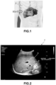
- the widely established practice worldwide is currently to perform such an ultrasound examination of the liver using a so-called “intercostal" scan configuration, denoted SCx ( figure 1 ), that is, by positioning the ultrasound probe so that the ultrasound waves propagate between the subject's ribs 2 in order to recover in return an ultrasound echo representative of the subject's liver 3.
- SCx so-called "intercostal" scan configuration
- the ultrasound probe possibly coated with suitable gel, is positioned in contact with the subject's skin at the level of his rib cage, so as to scan "through the ribs", that is, between the ribs.
- This intercostal scan configuration is considered the most reliable, particularly because the subject's ribs protect the underlying tissues and therefore limit the deformations that the probe can cause when it is applied in contact with the patient. Such deformations can indeed distort the results of the observation, as the compressed tissues then behave differently.
- the intercostal configuration is also preferred because it facilitates the examination, particularly for certain subjects who are difficult to examine (in particular those with a high level of subcutaneous fat).
- the ultrasound technician can use the subject's ribs as a reference point to best orient and position the ultrasound system probe.
- liver ultrasound observation using the classic intercostal scan configuration generally suffers from sometimes unsatisfactory results. It has been found that the assessment of some liver characteristics, such as some biomarkers, is not always sufficiently powerful or reliable in such uses.
- the present disclosure therefore proposes to provide a solution in particular to the problems and deficiencies mentioned above, making it possible to determine with greater reliability and better performance the state of the liver of a subject, such as a human being or an animal, or more generally the state of the liver of a living being for example, in particular but not exclusively to help in the screening or diagnosis of liver disorders, or more generally to evaluate the state of the liver of the subject.
- This solution is based in particular on a method and a device for determining the state of the liver of a subject.
- Determination methods and determination devices also called “methods” and “devices” will be described in the following according to particular embodiments of the disclosure with joint reference to Figures 3 to 16 .
- elements common or similar to several figures bear the same reference signs and have identical or similar characteristics, so that these common elements are generally not described again for the sake of brevity.
- first(s) "second(s)”, etc. are used in this document by arbitrary convention to allow different elements (such as operations, devices, etc.) implemented in the embodiments described below to be identified and distinguished.
- ultrasound waves W are emitted in different regions (or areas of interest) of the subject UR1 using the ultrasound system SY1 in order to obtain ultrasound data representative of the state of the liver 3.
- This observation comprises several ultrasound scans, i.e. several phases during which ultrasound waves propagate and ultrasound echoes representative of the state of the liver 3 are recovered in return.
- one or more regions of the liver are insonified by incident ultrasound waves and echoes backscattered by these regions of the liver are captured in return by means of an ultrasound probe.
- the terms "scan”, “ultrasound scan”, “ultrasound observation”, “ultrasound observation phase” or “acquisition phase” will subsequently be used interchangeably.
- the subject is a living being, namely a mammal, for example a human being. It should be noted, however, that the concept of the present disclosure may apply more generally to any subject provided with a liver, (human or animal), living or dead, whose condition of the liver is to be assessed.
- the subject UR1 used to illustrate the present disclosure may have a body in any physiological state, in particular at the hepatic level.
- the subject's liver 3 may in particular be healthy (for example no particular hepatic disorder) or suffer from any hepatic disorder or pathology.
- the method and device of the present disclosure are based in particular on obtaining two groups of data, respectively from ultrasound waves W propagating during ultrasound scans, of the same subject, according to different scan configurations, at least one of these configurations being a liver scan configuration, and on combining these two groups of data to determine an indicator noted S3 (also called global indicator, or global score, or parameter) which is representative of the state of the liver 3 of the subject UR1.
- an indicator noted S3 also called global indicator, or global score, or parameter
- a liver scan configuration as used herein refers to a scan configuration in which ultrasound data representative of the subject's liver are obtained. That is, an ultrasound scan performed in accordance with a liver scan configuration scans (or aims at, or targets), at least in part, the subject's liver, so as to obtain ultrasound data representative of said liver.
- a first scan SC1 and a second scan SC2 which are carried out using the ultrasound system SY1 on a subject UR1 according to different scan configurations (or modes) - denoted respectively CF1 and CF2 - in order to determine the state of the liver 3 of the subject UR1.
- the scan configurations CF1 and CF2 may vary depending on the case, in particular in terms of scan direction and/or position relative to the subject, to the extent however that these configurations are slightly or more generally different from each other.
- a determination device 30 is further configured to obtain and process scan data (or ultrasound data) DT1a and DT1b generated by the ultrasound system SY1 from the first and second scans SC1 and SC2 respectively ( figure 3 ). To do this, the determination device 30 cooperates (is coupled) with the ultrasound system SY1 to implement the determination method according to at least one particular embodiment.
- the determination device 30 and the ultrasound system SY1 together form a determination system (or analysis system) SY2, this system being configured to determine the condition of a subject's liver.
- the determination device 30 is an integral part of the ultrasound system SY1. According to one variant, the determination device 30 is external to (separate from) the ultrasound system SY1.
- the SY1 system may be a medical ultrasound system. Accordingly, the transmitter device 20 may be a (or at least partially part of a) medical and/or ultrasound probe.
- FIG 3 schematically represents an exemplary embodiment of the SY1 ultrasound system which comprises a control device (or piloting device) 10 and a transmitter device 20.
- the control device 10 is configured to control the transmitter device 20.
- the transmitter device 20 is configured to transmit and receive ultrasonic waves W, to and from a study environment, namely the subject UR1 in the examples considered, and this under the control of the control device 10.
- all or part of the determination device 30 is part of the control device 10. According to one example, the devices 10 and 30 form a single device.
- the emitting device 20 is for example an ultrasound transducer device (or ultrasound probe) configured to emit and/or receive ultrasound waves W.
- This emitting device 20 is for example included in an ultrasound probe intended to be applied in contact with the subject UR1 during ultrasound scans to determine the state of his liver 3.
- control device 10 can be implemented in the transmitter device 20 (for example in the probe). All or part of the control device 10 can be external to the transmitter device 20 (or to the probe).
- the control system 10 may comprise in this example a processing unit (or module) 11 and a control unit (or module) 12.
- the control unit 12 (also called a power control unit) is configured to control the emitting device 20 by means of electrical signals which are exchanged (or transmitted) between the system 10 and the transducer device 20.
- the control unit 12 thus generates electrical signals which are transmitted to the transducer device 20 to cause the emission, by said transducer device 20, of ultrasonic waves W1 towards the area of interest, located in the subject UR1.
- the electrical signals thus generated are representative of (or define the) ultrasonic waves projected into the medium.
- the control unit 12 may for example be or comprise at least one electronic pulser, also called a “pulser”.
- the control unit 12 may optionally include receiver devices or receiver circuits (not shown) configured to receive electrical signals from the transducer device 20.
- the processing unit 11 may be configured to control the control unit 12, for example by controlling the electrical signals.
- This processing unit 11 may for example be or comprise at least one processor.
- the processing unit 11 and/or the control unit 12 are included in the body 31 (central element) of the system SY1 shown for illustration purposes in figure 4 .
- the processing unit 11 can be configured to control electrical signals that are generated by the control unit 12.
- the processing unit 11 can also be configured to process (and/or interpret) electrical signals possibly received by the control unit 12 from the transmitter device 20.
- These signals are representative of waves W2 received by the transducer device 20 from the subject UR1 ( figure 3 ).
- These waves W2 form for example one or more ultrasonic echoes, that is to say a response of the medium studied (namely the liver of the subject UR1) to the ultrasonic waves emitted in the direction of said medium.
- the processing carried out by the processing unit 11 on the signals received may vary according to the case and comprise for example at least any one of amplification, filtering, digitization and signal conditioning operations.
- the term “medium” refers in this disclosure to one or more areas of interest (or regions) of the subject UR1, i.e. the areas which are insonified or scanned by ultrasound, namely areas of interest of the liver 3 and possibly areas of interest corresponding to other parts of the subject UR1.
- the transmitter device 20 may comprise for example one or more ultrasonic transducers (also called transducer elements) 22, each being configured to convert an electrical signal received from the control device 10 into ultrasonic waves (and possibly also vice versa).
- the transducers 22 may thus be configured to emit waves (or ultrasonic pulses, or ultrasonic beams) W1 into the medium, which corresponds to an emission operation.
- the transducers 22 may optionally also be configured to receive during a reception operation ultrasound signals W2 from one or more areas of interest of the subject UR1, for example in response to the transmitted waves W1. These received signals W2 may take the form of a set of echo signals backscattered in response to the previously transmitted signals W1. Each transducer 22 may for example convert a received echo signal W2 into an electrical signal. The signal may then be processed by the control device 10 (for example by the processing unit 11) or by any associated (dedicated) system, directly connected or not. For example, the signal W2 may be amplified, filtered, digitized and/or a signal conditioning operation may be performed.
- the transducer elements may be arranged in a line of transducers, a matrix, or as a network of transducers or any other configuration.
- the same transducer(s) 22 may be used to emit waves (or pulses) W1 and, where appropriate, receive the waves W2 forming the response of the medium, or different transducers may be used for the emission and reception of the waves. There may be one or more emission transducers, and possibly a plurality of reception transducers. In another variant, the same transducer 22 may be used for the emission and reception of the ultrasonic waves.
- the transducers 22 may comprise piezoelectric crystals and/or other components that may be configured to generate and/or record and/or receive signals.
- the control device 10 may comprise the transmitter device 20.
- the transmitter device 20 may be external to the control device 10.
- the transmitter device 20 may be connected to the control device 10 by a cable or may communicate wirelessly with it.
- the transmitter device 10 may for example comprise a battery and receive communication signals from the control device 10 that represent the electrical signals (e.g. the driving frequencies and/or any information included in the electrical signals). The transmitting device 20 can then reproduce the electrical signals internally from the received communication signals.
- the transmitting device 20 may for example be a conventional ultrasound transmitting device.
- a difference according to the present disclosure may reside in the manner in which the ultrasound data DT1a and DT1b are obtained and processed by the determining device 30 to determine the condition of the liver 3 of the subject UR1, as described in more detail below.
- the control device 10 may be stationary or mobile.
- the transmitter device 20 may also be stationary or mobile.
- the control device 10 may be a fixed system (e.g. comprising a processing unit and a display device, as described below) and the transmitter device 20 may be mobile (e.g. a sensor device, a measuring device, or a probe).
- the transmitter device 20 is integrated into the control device 10, and that the device 10 is a mobile system.
- the control device 10 may be configured to be driven autonomously, for example by an included battery. Other examples are described below.
- control device 10 may include at least one memory (not shown) used by the processing unit 11 to control the control unit 12. This memory may optionally be part of the processing unit 11.
- the processor and memory of the processing unit 11 may be incorporated into the control device 10 illustrated in figure 3 or may be incorporated into a computer or a computing device communicatively linked thereto.
- the memory of the control device 10 may be volatile (such as RAM), non-volatile (such as ROM, flash, EEPROM, etc. or any other storage device and/or computer-readable medium as described below) or a combination of both.
- This memory may, for example, be managed in DMA mode (for "Direct Memory Access” in English).
- the memory used by the unit processing unit 11 may for example comprise all or part of a graphics card (or video card) memory, this type of memory being in particular capable of processing and/or sending image data which can be used to display one or more images on a display screen (or unit).
- control device 10 may comprise storage devices (removable and/or non-removable), including, but not limited to, magnetic or optical disks or tapes.
- control device 10 may include one or more input devices such as a keyboard, mouse, pen, voice input, etc. and/or one or more output devices such as one or more displays, speakers, printer, etc.
- the environment may also include one or more communication connections, such as LAN, WAN, point-to-point, etc. In some embodiments, the connections may be used to establish point-to-point communications, wired communications, wireless communications, etc.
- the control device 10 may be a single computer operating in a networked environment using logical connections with one or more remote computers.
- the remote computer may be a review station, a personal computer, a server, a router, a network PC, a peer device, or other common network node, and may generally include several or all of the elements described above as well as others not mentioned.
- the logical connections may include any method supported by the available communications media.
- the determination device 30 comprises processing means for obtaining and processing the scan data (or ultrasound data) DT1a and DT1b generated by the ultrasound system SY1 ( figure 3 ).
- the scan data generated by the SY1 system can be analyzed by the determination device 30 either in real time, for example by means of an algorithm and/or from an artificial intelligence module, either analyzed later and/or in a location other than that in which the SY1 ultrasound system is located.
- the nature of the DT1a and DT1b scan data provided by the SY1 ultrasound system to the determination device 30 may vary depending on the case.
- This data may include, for example, image data (or video data) and/or other data obtained from the scan data or the scan data itself.
- the determination device 30 comprises at least one processor 31 and at least one computer-readable medium such as a non-volatile memory 32.
- This memory 32 rewritable or of the ROM type, constitutes a recording medium (or information medium) conforming to a particular embodiment, readable by the processor 31, and on which is recorded a computer program PG1 conforming to a particular embodiment.
- This computer program PG1 comprises instructions for executing the steps of a determination method according to at least one particular embodiment.
- This program can in particular define instructions for processing ultrasound data and/or instructions for constructing illustrative images of the observed medium.
- the computer program PG1 may for example comprise at least one artificial intelligence (AI) algorithm executable by the processor 31 to implement the determination method according to a particular embodiment of the present disclosure.
- the computer program PG1 may in particular define an artificial intelligence model (or predictive model) trained using training data to process the ultrasound data obtained according to the determination method of the present disclosure, in particular to determine one or more indicators (or scores) as described below in exemplary embodiments.
- the computer-readable media of the determining device 30, such as the memory 32, may be any available media that the processor 31 or its operating environment can access.
- the computer-readable media may include computer storage media and communication media.
- Computer storage media include volatile and non-volatile, removable and non-removable media, implemented in any method or technology for storing information such as computer-readable instructions, data structures, program modules or other data.
- Computer storage media do not include communication media.
- the determination device 30 is configured to receive scan data, such as the DT1a and DT1b data, provided by the ultrasound system SY1, process this data, and possibly send a result of this processing to an external device, such as for example, a storage device, display device, a server, or any other external device.
- scan data such as the DT1a and DT1b data
- an external device such as for example, a storage device, display device, a server, or any other external device.
- Communication between the determination device 30 and the ultrasound system SY1 can be carried out using any communication link, wired or wireless as the case may be.
- FIG 4 schematically represents an exemplary embodiment of the SY1 ultrasound system as previously described with reference to the figure 3 , namely an ultrasound imaging system in the examples considered.
- the probe 20 may be connected to the processing unit 40 by any suitable connection means such as a cable 21 or a wireless connection.
- the probe 20 is further capable of emitting ultrasonic waves W into a medium M, and possibly also of receiving ultrasonic waves W from the medium M, said received ultrasonic waves then being able to be consequent or resulting from reflections of said emitted ultrasonic waves on diffusing particles inside said medium.
- the processing unit 40 may comprise receiving devices (not shown), comprising (or being) for example receiving circuits, configured to process (for example amplify and/or filter) electrical signals received from the probe 20. These receiving devices may for example comprise converters to transform the received signals into data representing the signal (for example analog-to-digital converters (ADCs) configured to transform a voltage into a digital code).
- ADCs analog-to-digital converters
- the ultrasound data obtained may be processed in various ways; in particular, they may be temporarily stored in a memory accessible to the processing unit or processed directly to calculate intermediate processed data (data resulting from a beamforming process).
- the processing unit 30 may implement any known processing method to generate and/or process one or more images or maps or data on the basis of the signals received from the probe, such as beamforming.
- the display screen 50 (for example mounted on a support arm 51) may be a screen for viewing the image processed by the processing unit 30 and/or may display various information depending on the use case, in particular help information or contextual gesture help adapted or adaptable by means of the touchpad 42.
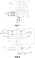
- the first MD2 obtaining module is configured to obtain a first group of DT1a scan data from ultrasound waves W1 propagating according to a first CF1 scan configuration of the liver 3 ( figure 3 ).
- These first DT1a scan data, obtained during a first SC1 ultrasound scan, are representative of liver 3 of subject UR1.
- the second MD4 obtaining module is configured to obtain a second group of DT1b scan data from ultrasound waves W1 propagating according to a second scan configuration CF2 of a group of tissues of the subject 3 ( figure 3 ).
- these second DT1a scan data, obtained during a second SC2 ultrasound scan are representative of any tissue group, which may include all or part of the liver 3 of subject UR1 or part (or region) of subject UR1 other than his liver 3 (e.g., an organ of the abdomen other than the liver, such as the pancreas and/or gallbladder).
- the MD6 determination module is configured to determine, by a combination of the first and second groups of scan data DT1a and DT1b, an indicator (or global indicator) S3 representative of the state of the liver 3 of the subject UR1.
- an indicator or global indicator
- S3 representative of the state of the liver 3 of the subject UR1.
- the processing applied to the DT1a and DT1b data to obtain the S3 indicator can be of various natures.
- the nature of the S3 indicator can vary depending on the case.
- the determination device 30 previously described implements the determination method according to exemplary embodiments by executing the program PG1 ( figure 3 ). To do this, the determination device 30 cooperates with the ultrasound system SY1.
- the SY1 ultrasound system emits W1 ultrasound waves towards the target medium (the part of the UR1 subject under observation) and receives back ultrasound echoes in the form of W2 waves ( figure 3 ).
- These ultrasonic waves W2 are representative of the region of the subject UR1 in which the emitted waves W1 and the received waves W2 propagate.
- the ultrasound system SY1 (and more particularly the control device 10) thus generates ultrasonic data, called first and second scan data DT1a and DT1b, from respectively the ultrasonic echoes captured during the ultrasonic scans SC1 and SC2.
- the region(s) of the subject UR1 that are the subject of the ultrasound observation, as well as the ultrasound echoes W2 obtained during this observation, are a function of the configuration of the ultrasound scans SC1 and SC2 performed.
- Various parameters can define these configurations, including in particular the orientation and/or the position of the emitting device 20 during the ultrasound scans.
- the first ultrasound scan SC1 is configured to scan (scrutinize) all or part of the liver 3 of the subject UR1.
- the scan configuration CF1 is such that the ultrasound waves propagating during the first scan SC1 are representative of an area of interest (or region) of the liver 3.
- the first ultrasound scan SC1 is therefore a scan of one or more areas of interest of the liver.
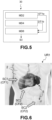
- the second ultrasound scan SC2 is configured to target (or scan) a tissue group 5 of the subject UR1 ( figure 6 ), the nature of these tissues may vary depending on the case.
- the CF2 scan configuration is such that the ultrasound waves propagating during the second SC2 scan are representative of tissue group 5.
- tissue group 5 scanned during the second scan SC2 includes all or part of the liver (liver scan).
- scan configurations (or modes) CF1 and CF2 are liver scan configurations.
- the tissue group 5 examined comprises (or corresponds to) a part (or region) of the subject UR1 other than its liver 3, such as for example all or part of its gallbladder, an organ of the abdomen and/or the visceral fat of the subject UR1.
- liver 3 considering information regarding the status of a region other than the subject's liver 3 may aid in the analysis and understanding of the status of liver 3, particularly because the status of liver 3 and that of other regions of the subject may be correlated.
- ultrasound observation of the visceral fat of subject UR1 may provide useful information for determining the condition of the liver 3, particularly to aid in the screening or diagnosis of a liver disorder, because visceral fat may be a biomarker of a pathological condition of the liver.
- An excessive presence of visceral fat may for example be symptomatic of hepatic steatosis (e.g. of the SHNA type), liver intoxication, or other liver condition.
- Tissue group 5 may be chosen based on the type of examination envisaged, and/or the supposed state of the liver that one wishes to study or confirm or which one wishes to wishes to study changes over time or in relation to a treatment, for example during a medical examination. Regardless of the region 5 of the subject that is scanned during the second ultrasound scan SC2, the first and second scan configurations CF1 and CF2 are different in order to obtain ultrasound data carrying different and complementary information.
- the determination device 30 obtains a first group of DT1a scan data from ultrasonic waves propagating during the first ultrasound scan SC1 according to the first scan configuration CF1 of the liver 3.
- the determining device 30 obtains a second group of scan data DT1b from ultrasonic waves propagating during the second ultrasound scan SC2 according to the second scan configuration CF2 of the tissue group 5.
- the ultrasound system SY1 (and more particularly the control device 10) generates the scan data DT1a and DT1b from the ultrasonic echoes received during the first and second ultrasonic scans SC1 and SC2 respectively. These scan data DT1a and DT1b are transmitted to the processing device 30 for processing according to the determination method.
- Each ultrasound scan SC1 and SC2 may include one or a plurality of scans in the corresponding scan configuration CF1 and CF2, respectively.
- the E2a and E2b obtaining steps are included in an obtaining phase noted E2 ( figure 8 ). It should be noted, however, that various arrangements of steps E2a and 2b are possible in time. Steps E2a and E2b can be performed either simultaneously (at least in part), or one after the other, or immediately after, or at another time (for example during different examination sessions). According to one example, the first group of scan data DT1a is received before the second group of scan data DT1b (or vice versa).
- the determination device 30 can receive the scan data DT1a and DT1b in real time, while the scans SC1 and SC2 are being performed, or later, in batches or separately.
- the determination device 30 determines, by a combination of the first and second groups of scan data DT1a and DT1b, an indicator (or score) S3 representative of the state of the liver 3 of the subject UR1.
- This combination may comprise a processing taking into account the DT1a and DT1b data, the nature of this processing being able to be adapted according to the case as described below in examples.
- Steps E2-E6 can be repeated iteratively to improve or update the indicator S3 determined in E6.
- the S3 indicator defines a (or at least one) biomarker of a physiopathological state of the liver.
- the S3 indicator can for example provide information on a liver disorder affecting the liver 3 of the UR1 subject, for example hepatic steatosis (of the SHNA type for example), steatohepatitis, liver intoxication, etc.
- the indicator S3 determined in E6 includes an attenuation coefficient which represents an attenuation of ultrasonic waves during their propagation in the areas of interest of subject UR1 during the first and second ultrasound scans SC1 and SC2, respectively.
- the indicator S3 determined in E6 includes an indicator defining for example a percentage (or rate) of liver fat mass (or PDFF). This percentage provides information on the average quantity of fat present in the liver 3 of subject UR1.
- FIG 11 represents, in the form of a 70-point statement, the S3 indicators determined (E6) for a group of test subjects during an ET1 study carried out by the applicant.
- the S3 indicators define a fat mass rate, or PDFF, determined respectively for each subject in the ET1 study.
- FIG 12 represents, for reference, the PDFF values determined for identical subjects in study ET1 by a technique other than that of the determination method, namely by MRI imaging.
- the assessment of PDFF by MRI imaging is currently the reference for detecting or diagnosing hepatic steatosis. It should be noted that this ET1 study concerns in this case subjects presenting a PDFF lower than a limit value, namely 25%.
- the S3 indicator determined in E6 may be representative of any physiological, mechanical and/or tissue property of the liver 3 and/or tissues 5 scanned by ultrasound (elasticity, hardness, etc.) during the ultrasound scans SC1 and SC2.
- the indicator S3 may comprise one indicator (or score) or a plurality of indicators (or scores).
- the determining device 30 compares (E8) the indicator S3 obtained in E6 with a reference value RF1.
- This reference value RF1 can be any reference indicating a predetermined state of a liver (healthy state, particular liver disorder, etc.). For example, if the device 30 detects (E8) that the value of the indicator S3 obtained in E6 exceeds (or is less than) the reference value, this means that the state of the liver 3 of the subject UR1 complies (or does not comply) with at least one predefined criterion.
- the S3 indicator can be determined in various ways by combining the DT1a and DT1b scan data resulting from the SC1 and SC2 ultrasound scans.
- the scan data DT1a and DT1b are data that are directly combined by the determination device 30 to deduce the indicator S3.
- the determination method 30 applies for example a calculation function, called “f1”, to the scan data DT1a and DT1b so as to produce the indicator S3.
- the determination device 30 performs a first processing on the scan data DT1a and DT1b before determining the indicator S3.
- the device 30 applies for example functions f2 and f3 on the scan data DT1a and DT1b respectively so as to produce intermediate scores (or indicators) S1 and S2.
- the determination device 30 evaluates (or determines) a first score S1 (E4a, figure 8 ) from the first group of DT1a scan data and evaluates (or determines) a second S2 score (E4b, figure 8 ) from the second group of DT1b scan data.
- the determination device 30 can then determine (E6) the score S3 from the first and second scores S1 and S2, for example by applying a function f4 on the intermediate scores S1 and S2.
- the types of intermediate scores S1 and S2 may vary depending on the case.
- the indicators S1 and/or S2 may each comprise at least one of the types of indicators as defined below.
- the first and second indicators S1 and S2 each comprise at least one indicator as defined below in particular examples.
- the indicators S1 and S2 determined in E4 each include a respective indicator defining a speed of sound, that is to say the speed of the ultrasonic waves propagating in the liver of the subject UR1, or more precisely in the insonified zone(s), during the corresponding ultrasonic scans SC1 and SC2.
- the indicators S1 and S2 determined in E4 each include a respective indicator defining a backscattering coefficient, i.e. a coefficient representative of a level of backscattering caused by the propagation of ultrasonic waves in the medium during the corresponding ultrasonic scans SC1 and SC2.
- This backscattering coefficient is one of the physical parameters linked to the capacity of the media probed to generate an echo propagating towards the ultrasonic probe.
- the indicators S1 and S2 determined in E4 each include a respective indicator (or score) of liver elasticity, that is, an indicator representative of the capacity of liver tissues to deform in response to a mechanical stress to which they are subjected.
- the indicators S1 and S2 determined in E4 each include a respective indicator (or score) defining a viscoelasticity of the liver, that is to say a coefficient representative of the viscosity and elasticity capacities of the liver.
- the indicators S1 and S2 determined in E4 each include a respective indicator (or score) of diffusion nonlinearity (or propagation nonlinearity), i.e. an indicator representative of the nonlinearity of propagation of ultrasound waves in the medium (in the liver) during the SC1 and SC2 ultrasound scans.
- the indicators S1 and S2 determined in E4 each include a respective diffusion indicator (or score), i.e. an indicator representative of a level of diffusion caused by the propagation of ultrasonic waves in the medium during the corresponding ultrasound scans SC1 and SC2.
- This diffusion coefficient can define a mean diffusion path (or "mean free path" in English) which is a function of the capacity of the insonified tissues to generate echoes resulting from multiple diffusion phenomena.
- Ultrasonic speckle also sometimes called “interference pattern” or “speckle” in ultrasound images is a phenomenon of apparent granularity or texture that results from the coherence of the ultrasound wave when it interacts with structures of various sizes within a tissue in the medium of interest. These granular patterns are the product of the constructive and destructive superposition of ultrasound waves reflected by multiple scatterers within the tissue, leading to a random variation in the intensity of the received signals. This characteristic can be used to extract information representative of a condition of the subject's liver, such as the texture of the observed tissues, their homogeneity and/or other material properties.
- the indicators S1 and S2 determined in E4 each include a respective speckle distribution indicator (or score) ultrasound (or an interference pattern distribution indicator).
- These indicators can characterize the distribution of the speckle phenomenon (or more simply of the speckle or of the gray levels) in one or more ultrasound images generated from respectively the first and second groups DT1a and DT1b of scan data (E2, figure 8 ). More particularly, from the first and/or second groups of scan data (steps E2a and E2b), B-mode ultrasound images can be generated and, for each image, the distribution of gray levels in the image can be determined.
- Statistical properties of the speckle can thus be represented in the form of at least one statistical speckle indicator, and used if appropriate to assess the condition of the subject's liver.
- the first score S1 is (or includes) a first attenuation coefficient and the second score S2 is (or includes) a second attenuation score.
- the intermediate scores S1 and S2 are thus representative of the attenuation of the ultrasonic waves propagating in the medium (the areas of interest) during the ultrasonic scans SC1 and SC2, respectively.
- the indicator S3 determined in E6 ( figure 8 ) from the combination of DT1a and DT1b scan data (and more precisely by combining the S1 and S2 scores) can define for example a biomarker of a physio-pathological state of the liver.
- the nature of the function f4 used by the device 30 to determine the indicator S3 from the intermediate scores S1 and S2 can be adapted as appropriate.
- the mean used to determine S3 is a linear minimum square mean of S1 and S2 (also called LSM for “Least mean-square”).
- the average of S1 and S2 used to determine (E6, figure 8 ) the indicator S3 is a non-linear combination of the scores S1 and S2.
- one of the weights a or b can be zero for at least one value of the pair (S1, S2), so that only the intermediate score S1 or S2 having a non-zero weight is selected and used to determine S3.
- the nonlinear combination of scores S1 and S2 can be defined as f(S1, S2) or f(DT1a, DT1b), where f denotes a nonlinear function.
- THE figures 9 represents, in the form of a statement of 62 points, the intermediate score S1 determined in E4a ( figure 8 ) from the first DT1a scan data for test subjects of a study marked ET1 carried out by the applicant.
- the figures 10 represents, in the form of a statement of 66 points, the intermediate score S2 determined in E4b ( figure 8 ) from the second DT1b scan data for the test subjects of study ET1.
- the intermediate scores S1 and S2 define in this example attenuation coefficients characterizing the attenuation of the ultrasound waves propagating in subject UR1 during the first and second ultrasound scans SC1 and SC2.
- Linear regressions 62a and 66a were determined from points 62 and 66, respectively, corresponding to the S1 and S2 scores resulting from the SC1 and SC2 ultrasound scans ( Figures 9 and 10 ). These linear regressions 62a and 66a represent the general evolution of the attenuation coefficients measured respectively in intercostal and subcostal positions as a function of the estimated PDFF score of each patient.
- the correlation coefficient reflects the correlation between the PDFF score and the attenuation indicator. If this coefficient is equal to 1, then all the points are located on the same straight line. We thus obtain in this case a slightly higher correlation in the subcostal configuration than in the intercostal configuration.
- the coefficient of determination r 2 also called Pearson's linear coefficient of determination, represents the quality of the prediction of a linear regression.
- FIG 11 represents, in the form of a 70-point statement, the S3 indicators determined (E6) for the group of test subjects, evaluated during the ET1 study.
- the S3 indicators define the attenuation indicator determined respectively for each subject of the ET1 study, from the combination of the subcostal and intercostal attenuation coefficients of each subject in the group.
- FIG 12 represents, for reference, the distribution of PDFF scores of the subjects of the ET1 study is determined by a technique other than that of the determination method, namely by MRI imaging.
- the evaluation of PDFF by MRI imaging currently constitutes the reference for detecting or diagnosing hepatic steatosis. It should be noted that this ET1 study concerns in this case subjects presenting a PDFF lower than a limit value, namely 25%.
- a linear regression 70a was also determined from the points 70 corresponding to the indicators S3 determined in E6 ( figure 8 ) for each test subject of study ET1.
- This linear regression 70a represents the general evolution of the overall attenuation coefficient as a function of the PDFF of the subjects.
- the linear regression 70a presents a better level of correlation of the overall attenuation coefficients S3 (than S1 and S2) with respect to the PDFF of the subjects, by comparison with the results obtained in intercostal mode alone ( figure 9 ) or in subcostal mode only ( figure 10 ). This validates for this example the effectiveness of the determination process which produces better results in terms of precision and reliability than if only one acquisition mode (intercostal or subcostal) was used.
- the determination device 30 evaluates (E10), from the indicator S3, a fat mass rate, or PDFF, of the liver 3 of the subject UR1.
- the device 30 can then optionally compare (E12) the PDFF obtained with a reference value RF2, this reference value being for example determined by an MRI imaging technique or other technology.
- first scan data DT1a may be obtained before, or at the same time, or after the second scan data DT1b.
- the first and second ultrasound scans SC1 and SC2 may be performed simultaneously or one after the other, in any order (SC1 before SC2 or SC2 before SC1), during the same scan session or different sessions.
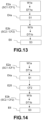
- one of the first and second scan data groups DT1a and DT1b is obtained from a scan, called an anterior scan, performed according to an anterior scan configuration and the other is obtained from a scan, called a posterior scan, performed according to a posterior scan configuration, the anterior scan being performed before the posterior scan.
- the anterior scan configuration is then one of the first and second scan configurations CF1 and CF2 and the posterior scan configuration is the other of the first and second scan configurations CF1 and CF2.
- the anterior scan is the first SC1 ultrasound scan performed according to the anterior scan configuration (i.e. CF1) and the posterior scan is the second SC2 ultrasound scan performed according to the scan configuration (i.e. CF2).
- the anterior scan configuration is the intercostal configuration and the posterior scan configuration is the subcostal configuration (the reverse is possible).
- the anterior scan is the second ultrasound scan SC2 performed according to the anterior scan configuration (i.e. CF2) and the posterior scan is the first ultrasound scan SC1 performed according to the scan configuration (i.e. CF1).
- the method for determining the disclosure can be carried out incrementally so that the determination device 30 generates a first result (for example S1 or S2) from the group of scan data resulting from the anterior scan, then to supplement this result with the scan data resulting from the posterior scan in order to obtain the overall indicator S3.
- a first result for example S1 or S2
- the determination device 30 generates a first result (for example S1 or S2) from the group of scan data resulting from the anterior scan, then to supplement this result with the scan data resulting from the posterior scan in order to obtain the overall indicator S3.
- the posterior scan configuration of the posterior scan (i.e. configuration CF2 of scan SC2 in this example) is selected (E25) from the first or second score S1 or S2 (i.e. S1 in this example) obtained from the anterior scan (i.e. SC1 in this example).
- the manner in which the posterior scan is performed can advantageously be adapted according to the result previously obtained for the anterior scan.
- the determination device 30 carried out during the determination step E6 ( figure 8 ) processing of the first and second groups of scan data DT1a and DT1b, or of data obtained from these DT1a and DT1b data, to determine the global indicator S3.
- This processing is carried out according to a processing model ML1 obtained by using one (or at least one) neural network RN1 trained from training data DT0 and scores (or indicators, or values) RF0 reference.
- the RN1 neural network may execute an algorithm based on an artificial intelligence module.
- the training data with which the RN1 neural network is trained may include ultrasound scan data or data obtained from such ultrasound scan data.
- the neural network RN1 is trained by machine learning during a training phase E40-E46.
- the neural network RN1 obtains (E40) ultrasound scan data DT0a and DT0b representative of waves propagating respectively according to the first and second scan configurations CF1 and CF2 on test subjects.
- the neural network RN1 determines (E42) training data DT0 from the ultrasound scan data DT0a and DT0b.
- This training data DT0 may comprise the scan data DT0a and/or DT0b themselves or data obtained from this data DT0a and/or DT0b.
- the RN1 neural network further obtains (E44), from MRI scans performed on the test subjects, RF0 reference scores representative of the state of the liver of the test subjects.
- the RN1 neural network can thus determine (E46), by comparing the DT0 training data with the RF0 reference scores, the ML1 processing model used to estimate the S3 indicator from the combination of the first and second groups of DT1a and DT1b scan data.
- the determination device 30 successively executes a first algorithm then a second algorithm to evaluate the state of the liver 3 of the subject UR1.
- the first algorithm is an estimation algorithm configured to determine a global attenuation coefficient S3 from the first and second groups of scan data DT1a and DT1b obtained in intercostal and subcostal mode, respectively. This first estimation is done for example by averaging the attenuation coefficients S1 and S2 obtained in intercostal and subcostal mode, as already described.
- the second algorithm is executed by a neural network (such as than the RN1 network) to estimate the PDFF of liver 3 of subject UR1 from the global attenuation coefficient S3, for example from the ML1 model or from a linear regression as previously described.
- the statistical model used in the second algorithm can thus correlate the global indicator S3 (representing for example at least one of the previously mentioned parameters: attenuation coefficients, speed of sound, etc.) and an estimate of the output PDFF.
- the determination device 30 can implement a neural network RN1 to generate a model ML1 making the correlation between ultrasound images acquired as input from the ultrasound scans SC1 and SC2, on the one hand, and the indicator S3 or the PDFF obtained as output.
- the method and the determination device of the present disclosure advantageously make it possible to reliably and efficiently determine the state of the liver of a subject who may be healthy or have any physiopathological state of the liver.
- the concept of the present disclosure is based on the combination of scan data (or ultrasound data) obtained according to two distinct scan configurations, namely according to respectively a first scan configuration CF1 targeting the liver and a second scan configuration CF2 targeting the liver or another group of tissues of the subject.
- the combination of these scan data advantageously makes it possible to obtain an indicator S3 representing more robustly the state of the liver of the subject than if a single scan configuration were used.
- the present disclosure is therefore not limited to the exemplary embodiments described above but extends in particular to a control method which would include secondary steps without thereby departing from the scope of the present disclosure. The same would apply to a control system for implementing such a method.
Landscapes
- Health & Medical Sciences (AREA)
- Life Sciences & Earth Sciences (AREA)
- Engineering & Computer Science (AREA)
- Medical Informatics (AREA)
- Public Health (AREA)
- General Health & Medical Sciences (AREA)
- Biomedical Technology (AREA)
- Physics & Mathematics (AREA)
- Pathology (AREA)
- Nuclear Medicine, Radiotherapy & Molecular Imaging (AREA)
- Heart & Thoracic Surgery (AREA)
- Surgery (AREA)
- Veterinary Medicine (AREA)
- Animal Behavior & Ethology (AREA)
- Molecular Biology (AREA)
- Radiology & Medical Imaging (AREA)
- Biophysics (AREA)
- Computer Vision & Pattern Recognition (AREA)
- Physiology (AREA)
- Data Mining & Analysis (AREA)
- Gastroenterology & Hepatology (AREA)
- Epidemiology (AREA)
- Primary Health Care (AREA)
- Theoretical Computer Science (AREA)
- Databases & Information Systems (AREA)
- General Physics & Mathematics (AREA)
- Software Systems (AREA)
- Endocrinology (AREA)
- Computing Systems (AREA)
- General Engineering & Computer Science (AREA)
- Evolutionary Computation (AREA)
- Mathematical Physics (AREA)
- Artificial Intelligence (AREA)
- High Energy & Nuclear Physics (AREA)
- Quality & Reliability (AREA)
- Gynecology & Obstetrics (AREA)
- Vascular Medicine (AREA)
- Ultra Sonic Daignosis Equipment (AREA)
Applications Claiming Priority (1)
| Application Number | Priority Date | Filing Date | Title |
|---|---|---|---|
| FR2306223A FR3149767A1 (fr) | 2023-06-16 | 2023-06-16 | Procédé et dispositif de détermination de l’état du foie d’un sujet |
Publications (1)
| Publication Number | Publication Date |
|---|---|
| EP4477153A1 true EP4477153A1 (de) | 2024-12-18 |
Family
ID=88068751
Family Applications (1)
| Application Number | Title | Priority Date | Filing Date |
|---|---|---|---|
| EP24176316.8A Pending EP4477153A1 (de) | 2023-06-16 | 2024-05-16 | Verfahren und vorrichtung zur bestimmung des leberzustands einer person |
Country Status (6)
| Country | Link |
|---|---|
| US (1) | US20240428404A1 (de) |
| EP (1) | EP4477153A1 (de) |
| JP (1) | JP2024180780A (de) |
| KR (1) | KR20240176775A (de) |
| CN (1) | CN119138924A (de) |
| FR (1) | FR3149767A1 (de) |
Families Citing this family (1)
| Publication number | Priority date | Publication date | Assignee | Title |
|---|---|---|---|---|
| US12616441B2 (en) * | 2024-09-11 | 2026-05-05 | Siemens Medical Solutions Usa, Inc. | Fat fraction estimation from tissue non-linear response with ultrasound medical imaging |
Citations (3)
| Publication number | Priority date | Publication date | Assignee | Title |
|---|---|---|---|---|
| CN102895003B (zh) * | 2011-07-27 | 2015-10-28 | 复旦大学附属中山医院 | 一种超声波图像量化诊断系统 |
| US20160317121A1 (en) * | 2013-12-16 | 2016-11-03 | Universitat Bern | Computed ultrasound tomography in echo mode (cute) for imaging speed of sound using pulse-echo sonography |
| JP2019088672A (ja) * | 2017-11-16 | 2019-06-13 | 国立大学法人九州大学 | 画像処理装置および画像処理装置の作動方法並びに画像処理プログラム |
Family Cites Families (4)
| Publication number | Priority date | Publication date | Assignee | Title |
|---|---|---|---|---|
| US10743814B2 (en) * | 2013-03-15 | 2020-08-18 | Siemens Medical Solutions Usa, Inc. | Fat fraction estimation using ultrasound with shear wave propagation |
| US11275159B2 (en) * | 2019-01-08 | 2022-03-15 | Shenzhen Mindray Bio-Medical Electronics Co., Ltd. | Attenuation estimation using ultrasound |
| KR102258776B1 (ko) * | 2019-05-20 | 2021-05-31 | 주식회사 힐세리온 | 인공지능형 초음파 지방간 자동 진단 장치 및 이를 이용한 원격 의료 진단 방법 |
| US20250090144A1 (en) * | 2021-12-17 | 2025-03-20 | Oncoustics Inc. | System and method for characterizing ultrasound data |
-
2023
- 2023-06-16 FR FR2306223A patent/FR3149767A1/fr active Pending
-
2024
- 2024-05-14 KR KR1020240063249A patent/KR20240176775A/ko active Pending
- 2024-05-14 JP JP2024078657A patent/JP2024180780A/ja active Pending
- 2024-05-15 US US18/665,179 patent/US20240428404A1/en active Pending
- 2024-05-16 EP EP24176316.8A patent/EP4477153A1/de active Pending
- 2024-05-28 CN CN202410672281.9A patent/CN119138924A/zh active Pending
Patent Citations (3)
| Publication number | Priority date | Publication date | Assignee | Title |
|---|---|---|---|---|
| CN102895003B (zh) * | 2011-07-27 | 2015-10-28 | 复旦大学附属中山医院 | 一种超声波图像量化诊断系统 |
| US20160317121A1 (en) * | 2013-12-16 | 2016-11-03 | Universitat Bern | Computed ultrasound tomography in echo mode (cute) for imaging speed of sound using pulse-echo sonography |
| JP2019088672A (ja) * | 2017-11-16 | 2019-06-13 | 国立大学法人九州大学 | 画像処理装置および画像処理装置の作動方法並びに画像処理プログラム |
Non-Patent Citations (1)
| Title |
|---|
| CASSINOTTO, C., JACQ, T., ANSELME, S., URSIC-BEDOYA, J., BLANC, P., FAURE, S., BELGOUR, A., GUIU, B.: "Diagnostic Performance of Attenuation to Stage Liver Steatosis with MRI Proton Density Fat Fraction as Reference: A Prospective Comparison of Three US Machines", RADIOLOGY, vol. 305, no. 2, 2022, pages 353 - 361, Retrieved from the Internet <URL:https://doi.org/10.1148/radiol.212846> |
Also Published As
| Publication number | Publication date |
|---|---|
| KR20240176775A (ko) | 2024-12-24 |
| FR3149767A1 (fr) | 2024-12-20 |
| CN119138924A (zh) | 2024-12-17 |
| US20240428404A1 (en) | 2024-12-26 |
| JP2024180780A (ja) | 2024-12-27 |
Similar Documents
| Publication | Publication Date | Title |
|---|---|---|
| EP3967239B1 (de) | Verfahren und system zur charakterisierung eines mediums mit ultraschall | |
| EP3824280B1 (de) | Verfahren und systeme zur nichtinvasiven charakterisierung eines heterogenen mediums mittels ultraschall | |
| Nguyen et al. | Shear wave elastography using amplitude-modulated acoustic radiation force and phase-sensitive optical coherence tomography | |
| Ho et al. | Using ultrasound Nakagami imaging to assess liver fibrosis in rats | |
| FR2971695A1 (fr) | Mesure de viscoelasticite en utilisant une onde a ultrason modulee par amplitude de phase | |
| EP3967240B1 (de) | Verfahren und system zur charakterisierung eines mediums mit ultraschall | |
| EP3967241B1 (de) | Verfahren und system zur charakterisierung eines mediums mittels ultraschall | |
| EP3968015A1 (de) | Methode und system zur charakterisierung eines mediums mittels ultraschall | |
| Ho et al. | Relationship between ultrasound backscattered statistics and the concentration of fatty droplets in livers: an animal study | |
| FR3072870A1 (fr) | Estimation viscoelastique d'un tissu a partir d'une vitesse de cisaillement dans une imagerie medicale a ultrasons | |
| EP4214500B1 (de) | Verfahren und system zur ultraschallcharakterisierung eines mediums | |
| EP3555611A1 (de) | Verfahren zur verarbeitung von signalen aus einer erfassung mittels ultraschallsondierung, entsprechendes computerprogramm und ultraschallbasierte sondierungsvorrichtung | |
| FR3104736A1 (fr) | Procédé ultrasonore pour quantifier l’élasticité non linéaire par ondes de cisaillement d’un milieu, et dispositif pour mettre en œuvre ce procédé | |
| US20240415489A1 (en) | Method of using multiparametric imaging data to diagnose disease states and to monitor their progression | |
| FR3149767A1 (fr) | Procédé et dispositif de détermination de l’état du foie d’un sujet | |
| FR2986960A1 (fr) | Procede et systeme de visualisation d'information associee dans une imagerie par onde de cisaillement ultrasonore ainsi que support de stockage lisible par ordinateur | |
| EP4574056A1 (de) | Verfahren zur charakterisierung eines zielobjekts in einem medium | |
| FR3150098A1 (fr) | Procédé et système de caracterisation ulstrasonore d’un milieu | |
| FR3150097A1 (fr) | Procédé et système de caracterisation ulstrasonore d’un milieu | |
| FR2871240A1 (fr) | Procede et systeme d'echographie de contraste | |
| WO2023037056A1 (fr) | Technique leam | |
| TWI924554B (zh) | 用於生成虛擬剪切波彈性影像之系統及方法 | |
| Sahshong et al. | Multi-task learning framework for elasticity and viscosity image reconstruction in ultrasound viscoelastography | |
| EP4712867A1 (de) | Vorrichtung und system zur tomographie der lunge und zugehöriges tomographieverfahren | |
| FR3163830A1 (fr) | Traitement d’élastographie ultrasonore pour caractériser un milieu d’intérêt |
Legal Events
| Date | Code | Title | Description |
|---|---|---|---|
| PUAI | Public reference made under article 153(3) epc to a published international application that has entered the european phase |
Free format text: ORIGINAL CODE: 0009012 |
|
| STAA | Information on the status of an ep patent application or granted ep patent |
Free format text: STATUS: THE APPLICATION HAS BEEN PUBLISHED |
|
| AK | Designated contracting states |
Kind code of ref document: A1 Designated state(s): AL AT BE BG CH CY CZ DE DK EE ES FI FR GB GR HR HU IE IS IT LI LT LU LV MC ME MK MT NL NO PL PT RO RS SE SI SK SM TR |
|
| STAA | Information on the status of an ep patent application or granted ep patent |
Free format text: STATUS: REQUEST FOR EXAMINATION WAS MADE |
|
| 17P | Request for examination filed |
Effective date: 20250617 |
|
| GRAP | Despatch of communication of intention to grant a patent |
Free format text: ORIGINAL CODE: EPIDOSNIGR1 |
|
| STAA | Information on the status of an ep patent application or granted ep patent |
Free format text: STATUS: GRANT OF PATENT IS INTENDED |
|
| RAP3 | Party data changed (applicant data changed or rights of an application transferred) |
Owner name: SUPERSONIC IMAGINE |