EP4007071B1 - Gleichförmig partitionierte hochpräzise unterreflektorvorrichtung mit einer zweistufigen lageeinstellfunktion - Google Patents
Gleichförmig partitionierte hochpräzise unterreflektorvorrichtung mit einer zweistufigen lageeinstellfunktion Download PDFInfo
- Publication number
- EP4007071B1 EP4007071B1 EP19939758.9A EP19939758A EP4007071B1 EP 4007071 B1 EP4007071 B1 EP 4007071B1 EP 19939758 A EP19939758 A EP 19939758A EP 4007071 B1 EP4007071 B1 EP 4007071B1
- Authority
- EP
- European Patent Office
- Prior art keywords
- rod
- adjustment
- reflector
- uniformly
- sub
- Prior art date
- Legal status (The legal status is an assumption and is not a legal conclusion. Google has not performed a legal analysis and makes no representation as to the accuracy of the status listed.)
- Active
Links
Images



Classifications
-
- H—ELECTRICITY
- H01—ELECTRIC ELEMENTS
- H01Q—ANTENNAS, i.e. RADIO AERIALS
- H01Q19/00—Combinations of primary active antenna elements and units with secondary devices, e.g. with quasi-optical devices, for giving the antenna a desired directional characteristic
- H01Q19/10—Combinations of primary active antenna elements and units with secondary devices, e.g. with quasi-optical devices, for giving the antenna a desired directional characteristic using reflecting surfaces
- H01Q19/18—Combinations of primary active antenna elements and units with secondary devices, e.g. with quasi-optical devices, for giving the antenna a desired directional characteristic using reflecting surfaces having two or more spaced reflecting surfaces
- H01Q19/19—Combinations of primary active antenna elements and units with secondary devices, e.g. with quasi-optical devices, for giving the antenna a desired directional characteristic using reflecting surfaces having two or more spaced reflecting surfaces comprising one main concave reflecting surface associated with an auxiliary reflecting surface
- H01Q19/192—Combinations of primary active antenna elements and units with secondary devices, e.g. with quasi-optical devices, for giving the antenna a desired directional characteristic using reflecting surfaces having two or more spaced reflecting surfaces comprising one main concave reflecting surface associated with an auxiliary reflecting surface with dual offset reflectors
-
- H—ELECTRICITY
- H01—ELECTRIC ELEMENTS
- H01Q—ANTENNAS, i.e. RADIO AERIALS
- H01Q15/00—Devices for reflection, refraction, diffraction or polarisation of waves radiated from an antenna, e.g. quasi-optical devices
- H01Q15/14—Reflecting surfaces; Equivalent structures
- H01Q15/147—Reflecting surfaces; Equivalent structures provided with means for controlling or monitoring the shape of the reflecting surface
-
- H—ELECTRICITY
- H01—ELECTRIC ELEMENTS
- H01Q—ANTENNAS, i.e. RADIO AERIALS
- H01Q15/00—Devices for reflection, refraction, diffraction or polarisation of waves radiated from an antenna, e.g. quasi-optical devices
- H01Q15/14—Reflecting surfaces; Equivalent structures
- H01Q15/16—Reflecting surfaces; Equivalent structures curved in two dimensions [2D], e.g. paraboloidal
- H01Q15/165—Reflecting surfaces; Equivalent structures curved in two dimensions [2D], e.g. paraboloidal composed of a plurality of rigid panels
-
- H—ELECTRICITY
- H01—ELECTRIC ELEMENTS
- H01Q—ANTENNAS, i.e. RADIO AERIALS
- H01Q3/00—Arrangements for changing or varying the orientation or the shape of the directional pattern of the waves radiated from an antenna or antenna system
- H01Q3/12—Arrangements for changing or varying the orientation or the shape of the directional pattern of the waves radiated from an antenna or antenna system using mechanical relative movement between primary active elements and secondary devices of antennas or antenna systems
- H01Q3/16—Arrangements for changing or varying the orientation or the shape of the directional pattern of the waves radiated from an antenna or antenna system using mechanical relative movement between primary active elements and secondary devices of antennas or antenna systems for varying relative position of primary active element and a reflecting device
- H01Q3/20—Arrangements for changing or varying the orientation or the shape of the directional pattern of the waves radiated from an antenna or antenna system using mechanical relative movement between primary active elements and secondary devices of antennas or antenna systems for varying relative position of primary active element and a reflecting device wherein the primary active element is fixed and the reflecting device is movable
Definitions
- the present invention relates to technical fields of communication, Telemetry, Track and Command (TT&C), and radio astronomy etc., and particularly to a uniformly-partitioned high-precision sub-reflector device with a two-stage position and pose adjustment function.
- T&C Telemetry, Track and Command
- radio astronomy etc. and particularly to a uniformly-partitioned high-precision sub-reflector device with a two-stage position and pose adjustment function.
- a dual-offset antenna has the characteristics that a main reflector is offset from a sub-reflector and the sub-reflector is offset from a feed.
- the dual-offset antenna overcomes not only an blockage of the sub-reflector to the main reflector, but also blockages of the feed and a supporting arm to the sub-reflector, thereby improving paraxial sidelobe characteristics of an antenna pattern and input voltage standing wave ratio characteristics of the feed, and achieving high antenna efficiency.
- Dual-offset Gregorian antenna has a compact structure with a large space between a primary feed and a sub-reflector, which can reduce a near-field effect and easily realize far-field conditions, and so is widely used.
- a feed-down offset antenna is employed in a lot of projects due to a low center of gravity and advantages for installation and maintenance of a receiving system.
- an international large scale scientific project - the Square Kilometre Array (SKA) radio telescope project adopts the feed-down dual-offset Gregorian reflector antenna.
- SKA Square Kilometre Array
- a geometric size of the sub-reflector and a relative positional relationship between the sub-reflector and the main reflector are both quite different from those of a circularly symmetric reflector antenna. How to precisely adjust the sub-reflector to a theoretical position is a key design problem. Otherwise, the position relationship between the main reflector and the sub-reflector will be incorrect, resulting in low antenna efficiency.
- the SKA project consists of 2,500 dual-offset reflector antennas with an aperture of 15 meters to receive weak radio signals from distant universe. Therefore, the antenna is required to have the characteristics of high efficiency, low noise, low cost and quick installation, wherein the antenna efficiency is required to be greater than 88% at 15GHz.
- a document ' DVA-C A Chinese Dish Prototype for the Square Kilometre Array' (2015 International Symposium on Antennas and Promotion ) introduces a development of a SKA prototype in China.
- a document ' The Design of the MeerKAT Dish Optics' (Electromagnetism in Advanced Applications, 2012 International Conference ) introduces a development of a SKA prototype in South Africa.
- a document ' Update on the SKA offset optics design for the U.S. Technology Development Project' (Aerospace, IEEE Conference, March 2011 ) introduces a development of a SKA prototype in Canada.
- the above three principle prototypes adopt an integral sub-reflector made of a composite material. Although this molding mode can simplify manufacturing procedures, the following defects are existed for the SKA project:
- a Chinese patent with a publication No. CN202712431U entitled 'Antenna Sub-Reflector System Comprising Fixed Adjusting Mechanism', discloses a device for adjusting a sub-reflector using a classical Stewart parallel mechanism.
- a Chinese patent with a publication No. CN105226370A entitled 'Antenna Structure System Based On 6/6-Upu Parallel Mechanism', discloses a device that uses a hexapod parallel mechanism as an antenna pedestal to realize a vertex tracking function.
- CN106450653A entitled 'Parallel Type Six-Freedom-Degree Redundant Driving Antenna Structural System', discloses a mechanism that realizes a negative angle in elevation for antenna by combining a hexapod parallel mechanism with a cone.
- a document ' Orientation of Radio-Telescope Secondary Mirror Via Parallel Platform' introduces a parallel mechanism with a six-degree-of-freedom adjustment for a sub-reflector.
- a document ' Stiffness Study of a Hexapod Telescope Platform' introduces a device using a hexapod mechanism as a pedestal of a planar antenna array.
- the above parallel mechanisms can realize a six-degree-of-freedom adjustment of an antenna or a sub-reflector, but for applications such as an adjustment of a sub-reflector of a dual-offset reflector antenna, the following defects are existed:
- a back of each panel needs to be provided with adjustment points.
- the traditional adjustment method of an antenna panel adopts several studs which are arranged on the back of the panel and then connected to an antenna backup structure. During adjustment, a movement of the antenna panel is realized by adjusting a screwing length of the studs.
- a Chinese patent with a publication No. CN202004142U entitled 'Positioning Connection Device of Combined Antenna Panel', discloses an antenna panel connection device using a combination of taper pins and screw nuts.
- a Chinese patent with a publication No. CN108172970A entitled ⁇ antenna panel assembling structure', discloses an antenna panel adjustment structure with a spherical hinge.
- a Chinese patent with a publication No. CN108155482A entitled ⁇ Structure of High-Precision Reflector Antenna Composite Panel and Adjustment Method thereof', discloses an adjustment method of a composite panel with a normal adjustment function.
- a document ' Design, construction, and performance of the Leighton 10.4-m-diameter radio telescopes' (Proceedings of the IEEE, May 1994 ) introduces a panel adjustment device with an aluminum honeycomb sandwich structure.
- a document ' Surface adjustment of the IRAM 30 m radio telescope' (Microwaves, Antennas & Propagation, IET, 2009 ) introduces an adjustment device with a truss structure panel.
- An objective of the present invention is to overcome the defects of the prior arts, and provides a uniformly-partitioned high-precision sub-reflector device with a two-stage position and pose adjustment function, which has the characteristics of high surface accuracy, high adjustment precision, high adjustment efficiency, high stiffness and light weight.
- the present invention has the following advantageous effects:
- the present invention is ingenious in conceptions, clear in ideas and easy to be realized, which not only solves the problems of the poor precision and the low efficiency of the traditional single-stage adjustment, but also improves the reliability and the design flexibility of the parallel mechanism, thereby achieving an important improvement of the prior arts.
- a dual-bias antenna is generally composed of a main reflector, a sub-reflector and a feed, wherein the sub-reflector is in the middle of an electromagnetic path between the main reflector and the feed for a secondary reflection of electromagnetic waves.
- the surface accuracy and position precision of the sub-reflector directly determine key specifications of the dual-offset antenna, such as efficiency, sidelobe and cross polarization.
- a sub-reflector adjustment device with an aperture of 5 meters in the dual-offset antenna is taken as an example.
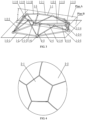
- a sub-reflector device of the present invention comprises an adjustment device 1, a sub-reflector 2, a single-layer space frame backup structure 3 and a panel precise adjustment device 4.
- the adjustment device 1 is located in a direction of an aperture of the sub-reflector 2 and does not obstruct the sub-reflector 2, and comprises a movable platform 1-1, a fixed platform 1-2, a primary adjustment rod 1-3, an auxiliary adjustment rod 1-4, a movable platform spherical joint 1-5 and a fixed platform spherical joint 1-6.
- the movable platform 1-1 is connected to the single-layer space frame backup structure 3
- the fixed platform 1-2 is located outside the aperture of the sub-reflector 2, and an included angle between a plane where the movable platform 1-1 is located and a plane where the fixed platform 1-2 is located is 0° to 30°.
- an included angle ⁇ between a plane A where the movable platform 1-1 is located and a plane B where the fixed platform 1-2 is located is 15°.
- the fixed platform 1-2 is a plane truss structure with a N-polygonal shape, wherein N is a natural number and N ⁇ 4.
- the fixed platform 1-2 is composed of N fixed platform rods 1-2-1 to 1-2-N, every two of which are connected by the fixed platform spherical joint 1-6.
- the fixed platform 1-2 has a pentagonal shape, and is composed of a fixed platform rod 1-2-1, a fixed platform rod 1-2-2, a fixed platform rod 1-2-3, a fixed platform rod 1-2-4 and a fixed platform rod 1-2-5.
- the movable platform 1-1 is a plane truss structure with a 2N-polygonal shape, and is composed of 2N movable platform rods 1-1-1 to 1-1-2N, every two of which are connected by the movable platform spherical joint 1-5.
- the movable platform 1-1 has a decagonal shape, and is composed of a movable platform rod 1-1-1, a movable platform rod 1-1-2, a movable platform rod 1-1-3, a movable platform rod 1-1-4, a movable platform rod 1-1-5, a movable platform rod 1-1-6, a movable platform rod 1-1-7, a movable platform rod 1-1-8, a movable platform rod 1-1-9 and a movable platform rod 1-1-10.
- At least one of the N fixed platform spherical joints 1-6 is corresponding to the movable platform spherical joint 1-5.
- five joints of the fixed platform spherical joints 1-6 are corresponding to the movable platform spherical joints 1-5.
- the primary adjustment rod 1-3 is composed of N rod, with two ends connected to the movable platform spherical joint 1-5 and the fixed platform spherical joint 1-6, respectively, and the number of the primary adjustment rods 1-3 is N.
- the number of the primary adjustment rods 1-3 is 5.
- auxiliary adjustment rod 1-4 Two ends of the auxiliary adjustment rod 1-4 are connected to the movable platform spherical joint 1-5 and the fixed platform spherical joint 1-6, respectively, and the number of the auxiliary adjustment rods 1-4 is 2N.
- the number of the auxiliary adjustment rods 1-4 is 10.
- Each of the primary adjustment rod 1-3 and the auxiliary adjustment rod 1-4 comprises spherical hinges located at the two ends thereof, and a threaded structure with an adjustable length located in the middle thereof.
- the movable platform rod 1-1, the fixed platform rod 1-2, the primary adjustment rod 1-3 and the auxiliary adjustment rod 1-4 form a mesh structure with a plurality of triangular space regions.
- the adjustment device 1 is a mesh structure composed of 15 triangular space regions.
- the sub-reflector 2 is composed of an N-polygonal panel 2-1 and N sectorial panels 2-2, wherein the N sectorial panels 2-2 are radially distributed around the N-polygonal panel 2-1 and each has an area substantially equal to that of the N-polygonal panel 2-1, and the sub-reflector 2 is connected to the single-layer space frame backup structure 3 through the panel precise adjustment device 4.
- the sub-reflector 2 is composed of a pentagonal panel 2-1 and five sectorial panels 2-2, with an area of the pentagonal panel 2-1 being 3.7m 2 and an area of the sectorial panel 2-2 being 3.4m 2 .
- the single-layer space frame back frame 3 is composed of an inner ring support 3-1, a main rod 3-2, a diagonal rod 3-3 and an inner spherical joint 3-4.
- the inner ring support 3-1 and the movable platform 1-1 are respectively located in two planes with a distance of 500 mm to 3000 mm therebetween.
- the distance between the two planes is 1000 mm.
- the inner ring support 3-1 has an N-polygonal shape, and is composed of N inner ring rods 3-1-1 to 3-1-N, every two of which are connected to each other through the inner ring spherical joint 3-4.
- the inner ring support 3-1 has a pentagonal shape, and is composed of an inner ring rod 3-1-1, an inner ring rod 3-1-2, an inner ring rod 3-1-3, an inner ring rod 3-1-4 and an inner ring rod 3-1-5.
- At least one of the N inner ring spherical joints 3-4 is corresponding to the movable platform spherical joint 1-5.
- the five inner ring spherical joints 3-4 are all corresponding to the movable platform spherical joints 1-5.
- Two ends of the main rod 3-2 are connected to the inner ring spherical joint 3-4 and the movable platform spherical joint 1-5, respectively, and the number of the main rods 3-2 is N.
- the number of the main rods 3-2 is 5.
- Two ends of the diagonal rod 3-3 are connected to the inner ring spherical joint 3-4 and the movable platform spherical joints 1-5, respectively, and the number of the diagonal rods 3-3 is 2N.
- the number of the diagonal rods 3-3 is 10.
- the inner ring rod 3-1-1, the movable platform rod 1-1-1 to 1-1-2n, the main rod 3-2 and the diagonal rod 3-3 form a mesh structure with a plurality of triangular space regions.
- the single-layer space frame backup structure 3 is a mesh structure composed of 15 triangular space regions.
- the panel precise adjustment device 4 comprises a positioning mechanism 4-1 and an adjustment mechanism 4-2.
- the positioning mechanism 4-1 is located at connection points between the N-polygonal panel 2-1 and the inner ring spherical joint 3-4 of the single-layer space frame backup structure 3, and connection points between the N sectorial panels 2-2 and the inner ring spherical joint 3-4 of the single-layer space frame backup structure 3.
- the number of the positioning mechanisms 4-1 is 10.
- the positioning mechanism 4-1 is composed of a main supporting rod 4-1-1, an independent supporting rod 4-1-2, a first direction connection plate 4-1-3, a second direction connection plate 4-1-4, a screw nut 4-1-5, a spherical washer 4-1-6, and a conical washer 4-1-7.
- An axial direction of the main supporting rod 4-1-1 is the same as a normal direction of the panel at the position of the main supporting rod 4-1-1.
- the first direction connection plate 4-1-3 is connected to the single-layer space frame backup structure 3 through the main supporting rod 4-1-1.
- the second direction connection plate 4-1-4 is connected to the panel through a fastener or glue.
- the first direction connection plate 4-1-3 and the second direction connection plate 4-1-4 are provided with oblong holes having extending directions orthogonal to each other.
- the independent supporting rod 4-1-2 is located between the first direction connection plate 4-1-3 and the second direction connection plate 4-1-4, with an upper end thereof located in the oblong hole of the second direction connection plate 4-1-4 and fixed by the screw nut 4-1-5, and a lower end thereof located in the oblong hole of the first direction connection plate 4-1-3 and fixed by the nut 4-1-5, the spherical washer 4-1-6, and the conical washer 4-1-7.
- the adjustment mechanism 4-2 is located at a non-working side of the antenna panel and composed of a V-shaped rod 4-2-1, a unidirectional rod 4-2-2, a dual-joint support 4-2-3 and a single-joint support 4-2-4.
- the V-shaped rod 4-2-1 comprises an A-link 4-2-1-1 and a B-link 4-2-1-2 with adjustable lengths and each having spherical hinges at two ends.
- One end of each of the A-link 4-2-1-1 and the B-link 4-2-1-2 is connected to the single-layer space frame backup structure 3, and the other end thereof is connected to the dual-joint support 4-2-3.
- the unidirectional rod 4-2-2 has an adjustable length and provided with spherical hinges at two ends thereof, wherein one end is connected to the single-layer space frame backup structure 3, and the other end is connected to the single-joint support 4-2-4.
- a ratio of a maximum curved surface area to a minimum curved surface area among the N-polygonal panel 2-1 and the N sectorial panels 2-2 is 1 to 1.3.
- the ratio of the maximum curved surface area to the minimum curved surface area among the pentagonal panel 2-1 and five sectorial panels 2-2 is 1.1.
- an intermediate threaded structure of the main adjustment rod 1-3 and the auxiliary adjustment rod 1-4 has an adjustable length and has left-handed and right-handed threads in combination.
- the spherical hinges at the two ends of each of the primary adjustment rod 1-3 and the auxiliary adjustment rod 1-4 are ball bearings.
- the inner ring rods 3-1-1 to 3-1-5, the movable platform rods 1-1-1 to 1-1-10, the main rod 3-2 and the diagonal rod 3-3 each comprises a circular tube, a conical head, a high-strength bolt and a screw nut.
- An intermediate threaded structure of the A-link 4-2-1-1, the B-link 4-2-1-2 and the unidirectional rod 4-2-2 has an adjustable length and has left-handed and right-handed threads in combination.
- the screw nut 4-1-5, the spherical washers 4-1-6 and the conical washers 4-1-7 are symmetrically distributed on two sides of the first direction connection plate 4-1-3.
- the dual-joint support 4-2-3 is located at a center of gravity of the antenna panel and connected thereto through a fastener or glue.
- the single-joint support 4-2-4 is located under the antenna panel and connected thereto through a fastener or glue.
- a gap between the N-polygonal panel 2-1 and the N sectorial panels 2-2 constituting the sub-reflector 2 is 0.2 to 5 mm.
- the gap between the pentagonal panel 2-1 and five sectorial panels 2-2 is 2 mm.
- the adjustment principle of the sub-reflector device of the present invention is as follows:
- the sub-reflector device of the present invention comprises an adjustment device, a sub-reflector, a single-layer space frame backup structure and a panel precise adjustment device.
- the adjustment device adopts movable and fixed platforms as a multi-rod six-degree-of-freedom sub-reflector adjustment mechanism for a plane truss to realize a primary pose adjustment of the sub-reflector.
- the sub-reflector is composed of a polygonal panel and several sectorial panels, and an area of each sectorial panel is substantially equal to that of the polygonal panel.
- the numbers of inner and outer sides of the single-layer space frame backup structure is in a ratio of 1: 2, which provides a support stiffness for the sub-reflector.
- the panel precise adjustment device comprises a positioning mechanism for adjusting the panel in a normal direction and an adjustment mechanism for adjusting a movement of the sub-reflector.
- a sub-reflector device not only realizes a two-stage position and pose adjustment of the sub-reflector, but also improves the integral stiffness and reduces the overall weight of the sub-reflector system, while improving the installation and adjustment efficiency and reducing the manufacturing cost.
Landscapes
- Physics & Mathematics (AREA)
- Electromagnetism (AREA)
- Aerials With Secondary Devices (AREA)
- Variable-Direction Aerials And Aerial Arrays (AREA)
Claims (25)
- Gleichförmig partitionierte hochpräzise Unterreflektorvorrichtung mit einer zweistufigen Positions- und Pose-Einstellfunktion, die eine Einstellvorrichtung (1), einen Unterreflektor (2), eine einlagige Raumrahmen-Stützstruktur (3) und eine Panel-PräzisionsEinstellvorrichtung (4) aufweist;wobei sich die Einstellvorrichtung (1) in einer Richtung einer Öffnung des Unterreflektors (2) befindet und eine bewegliche Plattform (1-1), eine feste Plattform (1-2), eine Haupteinstellstange (1-3), eine Hilfseinstellstange (1-4), ein Kugelgelenk (1-5) der beweglichen Plattform und ein Kugelgelenk (1-6) der festen Plattform aufweist; die bewegliche Plattform (1-1) mit der einlagigen Raumrahmen-Stützstruktur (3) verbunden ist und die feste Plattform (1-2) sich außerhalb der Öffnung des Unterreflektors (2) befindet; die feste Plattform (1-2) eine ebene Fachwerkstruktur mit einer N-polygonalen Form ist, wobei N eine natürliche Zahl und N ≥ 4 ist; die feste Plattform (1-2) aus N Stangen der festen Plattform (1-2-1 bis 1-2-N) zusammengesetzt ist, von denen jeweils zwei durch das Kugelgelenk (1-6) der festen Plattform verbunden sind; die bewegliche Plattform (1-1) eine ebene Fachwerkstruktur mit einer 2N-polygonalen Form ist und aus 2N Stangen (1-1-1 bis 1-1-2N) der beweglichen Plattform zusammengesetzt ist, von denen jeweils zwei durch das Kugelgelenk (1-5) der beweglichen Plattform verbunden sind; die Stange (1-1-1 bis 1-1-2N) der beweglichen Plattform, die Stange (1-2-1 bis 1-2-N) der festen Plattform, die Haupteinstellstange (1-3) und die Hilfseinstellstange (1-4) eine Netzstruktur mit mehreren dreieckigen Raumgebieten bilden;der Unterreflektor (2) aus einem N-polygonalen Panel (2-1) und N sektoriellen Panels (2-2) zusammengesetzt ist, wobei die N sektoriellen Panels (2-2) radial um das N-polygonale Panel (2-1) herum verteilt sind und jeweils eine Fläche aufweisen, die im Wesentlichen gleich derjenigen des N-polygonalen Panels (2-1) ist, und der Unterreflektor (2) durch die Panel-Präzisionseinstellvorrichtung (4) mit der einlagigen Raumrahmen-Stützstruktur (3) verbunden ist;die einlagige Raumrahmen-Stützstruktur (3) aus einem Innenringträger (3-1), einer Hauptstange (3-2), einer Diagonalstange (3-3) und einem Innenringkugelgelenk (3-4) zusammengesetzt ist; wobei der Innenringträger (3-1) eine N-polygonale Form aufweist und aus N Innenringstangen (3-1-1 bis 3-1-N) zusammengesetzt ist, von denen jeweils zwei durch das Innenringkugelgelenk (3-4) miteinander verbunden sind; die Innenringstange (3-1-1), die Stange (1-1-1 bis 1-1-2N) der beweglichen Plattform, die Hauptstange (3-2) und die Diagonalstange (3-3) eine Netzstruktur mit mehreren dreieckigen Raumgebieten bilden;die Panel-Präzisionseinstellvorrichtung (4) einen Positioniermechanismus (4-1) und einen Einstellmechanismus (4-2) aufweist, wobei sich der Positioniermechanismus (4-1) an Verbindungspunkten zwischen dem N-polygonalen Panel (2-1) und dem Innenringkugelgelenk (3-4) der einlagigen Raumrahmen-Stützstruktur (3) und Verbindungspunkten zwischen den N sektoriellen Panels (2-2) und dem Innenringkugelgelenk (3-4) der einlagigen Raumrahmen-Stützstruktur (3) befindet; und wobei sich der Einstellmechanismus (4-2) an einer nicht arbeitenden Seite eines Antennenpanels befindet.
- Gleichförmig partitionierte hochpräzise Unterreflektorvorrichtung nach Anspruch 1, wobei ein eingeschlossener Winkel zwischen einer Ebene, in der sich die bewegliche Plattform (1-1) befindet, und einer Ebene, in der sich die feste Plattform (1-2) befindet, 0° bis 30° beträgt.
- Gleichförmig partitionierte hochpräzise Unterreflektorvorrichtung nach Anspruch 2, wobei zumindest eines der N Kugelgelenke (1-6) der festen Plattform mit dem Kugelgelenk (1-5) der beweglichen Plattform korrespondiert.
- Gleichförmig partitionierte hochpräzise Unterreflektorvorrichtung nach Anspruch 3, wobei die Haupteinstellstange (1-3) aus N Stangen zusammengesetzt ist, wobei zwei Enden mit dem Kugelgelenk (1-5) der beweglichen Plattform bzw. dem Kugelgelenk (1-6) der festen Plattform verbunden sind und die Anzahl der Haupteinstellstangen (1-3) N ist.
- Gleichförmig partitionierte hochpräzise Unterreflektorvorrichtung nach Anspruch 4, wobei zwei Enden der Hilfseinstellstange (1-4) mit dem Kugelgelenk (1-5) der beweglichen Plattform bzw. dem Kugelgelenk (1-6) der festen Plattform verbunden sind und die Anzahl der Hilfseinstellstangen (1-4) 2N ist.
- Gleichförmig partitionierte hochpräzise Unterreflektorvorrichtung nach Anspruch 5, wobei von der Haupteinstellstange (1-3) und der Hilfseinstellstange (1-4) ein jede kugelförmige Gelenke, die sich an ihren beiden Enden befinden, und eine Gewindestruktur mit einer einstellbaren Länge, die sich in ihrer Mitte befindet, aufweist.
- Gleichförmig partitionierte hochpräzise Unterreflektorvorrichtung nach Anspruch 6, wobei der Innenringträger (3-1) und die bewegliche Plattform (1-1) jeweils in zwei Ebenen mit einem Abstand von 500 mm bis 3000 mm dazwischen angeordnet sind.
- Gleichförmig partitionierte hochpräzise Unterreflektorvorrichtung nach Anspruch 7, wobei zumindest eines der N Innenringkugelgelenken (3-4) mit dem Kugelgelenk (1-5) der beweglichen Plattform korrespondiert.
- Gleichförmig partitionierte hochpräzise Unterreflektorvorrichtung nach Anspruch 8, wobei zwei Enden der Hauptstange (3-2) mit dem Innenringkugelgelenk (3-4) bzw. dem Kugelgelenk (1-5) der beweglichen Plattform verbunden sind und die Anzahl der Hauptstangen (3-2) N ist.
- Gleichförmig partitionierte hochpräzise Unterreflektorvorrichtung nach Anspruch 9, wobei zwei Enden der Diagonalstange (3-3) mit dem Innenringkugelgelenk (3-4) bzw. dem Kugelgelenk (1-5) der beweglichen Plattform verbunden sind und die Anzahl der Diagonalstangen (3-3) 2N ist.
- Gleichförmig partitionierte hochpräzise Unterreflektorvorrichtung nach Anspruch 10, wobei der Positioniermechanismus (4-1) aus einer Haupthaltestange (4-1-1), einer unabhängigen Haltestange (4-1-2), einer Erstrichtungs-Verbindungsplatte (4-1-3), einer Zweitrichtungs-Verbindungsplatte (4-1-4), einer Schraubenmutter (4-1-5), einer kugelförmigen Unterlegscheibe (4-1-6) und einer konischen Unterlegscheibe (4-1-7) zusammengesetzt ist; wobei eine axiale Richtung der Haupthaltestange (4-1-1) die gleiche ist wie eine Normalenrichtung des Panels an der Position der Haupthaltestange (4-1-1); die Erstrichtungs-Verbindungsplatte (4-1-3) durch die Haupthaltestange (4-1-1) mit einlagigen Raumrahmen-Stützstruktur (3) verbunden ist; die Zweitrichtungs-Verbindungsplatte (4-1-4) durch ein Befestigungsmittel oder einen Klebstoff mit dem Panel verbunden ist; und sich die unabhängige Haltestange (4-1-2) zwischen der Erstrichtungs-Verbindungsplatte (4-1-3) und der Zweitrichtungs-Verbindungsplatte (4-1-4) angeordnet ist.
- Gleichförmig partitionierte hochpräzise Unterreflektorvorrichtung nach Anspruch 11, wobei die Erstrichtungs-Verbindungsplatte (4-1-3) und die Zweitrichtungs-Verbindungsplatte (4-1-4) mit Langlöchern, die zueinander orthogonale Erstreckungsrichtungen aufweisen, versehen sind.
- Gleichförmig partitionierte hochpräzise Unterreflektorvorrichtung nach Anspruch 12, wobei sich ein oberes Ende der unabhängigen Haltestange (4-1-2) in dem Langloch der Zweitrichtungs-Verbindungsplatte (4-1-4) befindet und durch die Schraubenmutter (4-1-5) befestigt ist, und sich ein unteres Ende der unabhängigen Haltestange (4-1-2) in dem Langloch der Erstrichtungs-Verbindungsplatte (4-1-3) befindet und durch die Schraubenmutter (4-1-5), die kugelförmige Unterlegscheibe (4-1-6) und die konische Unterlegscheibe (4-1-7) befestigt ist.
- Gleichförmig partitionierte hochpräzise Unterreflektorvorrichtung nach Anspruch 13, wobei der Einstellmechanismus (4-2) aus einer V-förmigen Stange (4-2-1), einer unidirektionalen Stange (4-2-2), einem Doppelverbindungshalter (4-2-3) und einem Einzelverbindungshalter (4-2-4) zusammengesetzt ist; wobei die V-förmige Stange (4-2-1) ein A-Glied (4-2-1-1) und ein B-Glied (4-2-1-2) mit einstellbaren Längen aufweist und jeweils kugelförmige Gelenke an zwei Enden besitzt; ein Ende des A-Glieds (4-2-1-1) und des B-Glieds (4-2-1-2) jeweils mit der einlagigen Raumrahmen-Stützstruktur (3) verbunden ist und das andere Ende davon mit dem Doppelverbindungshalter (4-2-3) verbunden ist; die unidirektionale Stange (4-2-2) eine einstellbare Länge aufweist und mit kugelförmigen Gelenken an zwei Enden davon versehen ist, wobei ein Ende mit der einlagigen Raumrahmen-Stützstruktur (3) verbunden ist und das andere Ende mit dem Einzelverbindungshalter (4-2-4) verbunden ist.
- Gleichförmig partitionierte hochpräzise Unterreflektorvorrichtung nach Anspruch 14, wobei ein Einstellbetrag des Panels durch den Einstellmechanismus (4-2) die folgenden Gleichungen erfüllt:


- Gleichförmig partitionierte hochpräzise Unterreflektorvorrichtung nach Anspruch 15, wobei ein Einstellbetrag des A-Glieds und des B-Glieds in einer y-Richtung die folgende Gleichung erfüllt:

- Gleichförmig partitionierte hochpräzise Unterreflektorvorrichtung nach Anspruch 16, wobei ein Einstellbetrag der unidirektionalen Stange in der x-Richtung und ein Einstellbetrag der unidirektionalen Stange in der y-Richtung die folgenden Gleichungen erfüllen:


- Gleichförmig partitionierte hochpräzise Unterreflektorvorrichtung nach Anspruch 17, wobei unter dem N-polygonalen Panel (2-1) und den N sektoriellen Panels (2-2) ein Verhältnis von einer maximalen gekrümmten Oberfläche zu einer minimalen gekrümmten Oberfläche 1 bis 1,3 ist.
- Gleichförmig partitionierte hochpräzise Unterreflektorvorrichtung nach Anspruch 18, wobei eine Zwischengewindestruktur der Haupteinstellstange (1-3) und der Hilfseinstellstange (1-4) eine einstellbare Länge besitzt und Links- und Rechtsgewinde in Kombination aufweist.
- Gleichförmig partitionierte hochpräzise Unterreflektorvorrichtung nach Anspruch 19, wobei die kugelförmigen Gelenke an den beiden Enden einer jeden von der Haupteinstellstange (1-3) und der Hilfseinstellstange (1-4) Kugellager sind.
- Gleichförmig partitionierte hochpräzise Unterreflektorvorrichtung nach Anspruch 20, wobei die Innenringstange (3-1-1 bis 3-1-N), die Stange (1-1-1 bis 1-1-2N) der beweglichen Plattform, die Hauptstange (3-2) und die Diagonalstange (3-3) jeweils ein ringförmiges Rohr, einen konischen Kopf, einen hochfesten Bolzen und eine Schraubenmutter aufweisen.
- Gleichförmig partitionierte hochpräzise Unterreflektorvorrichtung nach Anspruch 21, wobei eine Zwischengewindestruktur des A-Glieds (4-2-1-1), des B-Glieds (4-2-1-2) und der unidirektionalen Stange (4-2-2) eine einstellbare Länge besitzt und Links- und Rechtsgewinde in Kombination aufweist.
- Gleichförmig partitionierte hochpräzise Unterreflektorvorrichtung nach Anspruch 22, wobei die Schraubenmutter (4-1-5), die kugelförmige Unterlegscheibe (4-1-6) und die konische Unterlegscheibe (4-1-7) auf zwei Seiten der Erstrichtungs-Verbindungsplatte (4-1-3) symmetrisch verteilt sind.
- Gleichförmig partitionierte hochpräzise Unterreflektorvorrichtung nach Anspruch 23, wobei sich der Doppelverbindungshalter (4-2-3) in einem Schwerpunkt des AntennenPanels befindet und mit diesem durch ein Befestigungsmittel oder einen Klebstoff verbunden ist; und sich der Einzelverbindungshalter (4-2-4) unter dem Antennen-Panel befindet und mit diesem durch ein Befestigungsmittel oder einen Klebstoff verbunden ist.
- Gleichförmig partitionierte hochpräzise Unterreflektorvorrichtung nach Anspruch 24, wobei ein Spalt zwischen dem N-polygonalen Panel (2-1) und den N sektoriellen Panels (2-2), die den Unterreflektor (2) bilden, 0,2 mm bis 5 mm beträgt.
Priority Applications (1)
| Application Number | Priority Date | Filing Date | Title |
|---|---|---|---|
| DE19939758.9T DE19939758T1 (de) | 2019-07-26 | 2019-12-16 | Gleichförmig partitionierte hochpräzise Unterreflektorvorrichtung mit einer zweistufigen Positions- und Pose-Einstellfunktion |
Applications Claiming Priority (2)
| Application Number | Priority Date | Filing Date | Title |
|---|---|---|---|
| CN201910682977.9A CN110289498B (zh) | 2019-07-26 | 2019-07-26 | 具有两级位姿调整功能的均匀分块高精度副反射面装置 |
| PCT/CN2019/125478 WO2021017373A1 (zh) | 2019-07-26 | 2019-12-16 | 具有两级位姿调整功能的均匀分块高精度副反射面装置 |
Publications (3)
| Publication Number | Publication Date |
|---|---|
| EP4007071A1 EP4007071A1 (de) | 2022-06-01 |
| EP4007071A4 EP4007071A4 (de) | 2023-10-18 |
| EP4007071B1 true EP4007071B1 (de) | 2024-11-20 |
Family
ID=68022505
Family Applications (1)
| Application Number | Title | Priority Date | Filing Date |
|---|---|---|---|
| EP19939758.9A Active EP4007071B1 (de) | 2019-07-26 | 2019-12-16 | Gleichförmig partitionierte hochpräzise unterreflektorvorrichtung mit einer zweistufigen lageeinstellfunktion |
Country Status (6)
| Country | Link |
|---|---|
| EP (1) | EP4007071B1 (de) |
| CN (1) | CN110289498B (de) |
| DE (1) | DE19939758T1 (de) |
| ES (1) | ES2921899T3 (de) |
| WO (1) | WO2021017373A1 (de) |
| ZA (1) | ZA202202438B (de) |
Families Citing this family (8)
| Publication number | Priority date | Publication date | Assignee | Title |
|---|---|---|---|---|
| CN110289498B (zh) * | 2019-07-26 | 2024-02-13 | 中国电子科技集团公司第五十四研究所 | 具有两级位姿调整功能的均匀分块高精度副反射面装置 |
| CN111478054B (zh) * | 2020-05-18 | 2024-03-05 | 中国科学院国家天文台 | 一种fast反射面单元自适应连接机构及布局方法 |
| CN112018523B (zh) * | 2020-09-28 | 2024-11-22 | 中国电子科技集团公司第五十四研究所 | 一种充气式拼接天线 |
| CN114050421B (zh) * | 2021-08-19 | 2023-08-22 | 中国工程物理研究院应用电子学研究所 | 两维波束扫描高功率微波偏馈双反射面天线系统及应用 |
| CN113839211B (zh) * | 2021-08-30 | 2023-05-19 | 电子科技大学 | 一种基于平面阵列结构的卡塞格伦单脉冲天线 |
| CN118380750B (zh) * | 2024-06-14 | 2025-04-01 | 南京驰韵科技发展有限公司 | 一种星载反射面天线调节控制系统 |
| CN118746915A (zh) * | 2024-06-17 | 2024-10-08 | 集美大学 | 一种Stewart平台姿态控制方法、设备及介质 |
| CN119681556B (zh) * | 2025-02-27 | 2025-04-25 | 中色十二冶金建设有限公司 | 一种大跨度球形钢网架安装用辅助定位结构 |
Family Cites Families (10)
| Publication number | Priority date | Publication date | Assignee | Title |
|---|---|---|---|---|
| CN202004142U (zh) | 2010-12-16 | 2011-10-05 | 中国电子科技集团公司第五十四研究所 | 一种组合式天线面板定位连接装置 |
| CN202712431U (zh) * | 2012-08-27 | 2013-01-30 | 中国电子科技集团公司第五十四研究所 | 一种含有固定调整机构的天线副反射面系统 |
| US10241321B1 (en) * | 2015-05-06 | 2019-03-26 | Sciperio, Inc | Monolithic adaptive optical/RF reflector |
| CN105226370A (zh) | 2015-10-23 | 2016-01-06 | 上海创投机电工程有限公司 | 6/6-upu型并联机构天线结构系统 |
| CN106450653B (zh) * | 2016-09-08 | 2023-05-09 | 中国电子科技集团公司第五十四研究所 | 一种并联式六自由度冗余驱动天线结构系统 |
| CN108155482B (zh) * | 2017-12-25 | 2023-08-15 | 中国电子科技集团公司第五十四研究所 | 一种高精度反射面天线组合面板的结构及其调整方法 |
| CN108172970A (zh) | 2018-01-31 | 2018-06-15 | 中国电子科技集团公司第五十四研究所 | 一种天线面板装配结构 |
| CN109301452B (zh) * | 2018-09-19 | 2024-02-02 | 中国科学院遥感与数字地球研究所 | S/X/Ka三轴天线 |
| CN110289498B (zh) * | 2019-07-26 | 2024-02-13 | 中国电子科技集团公司第五十四研究所 | 具有两级位姿调整功能的均匀分块高精度副反射面装置 |
| CN210040562U (zh) * | 2019-07-26 | 2020-02-07 | 中国电子科技集团公司第五十四研究所 | 具有两级位姿调整功能的均匀分块高精度副反射面装置 |
-
2019
- 2019-07-26 CN CN201910682977.9A patent/CN110289498B/zh active Active
- 2019-12-16 EP EP19939758.9A patent/EP4007071B1/de active Active
- 2019-12-16 WO PCT/CN2019/125478 patent/WO2021017373A1/zh not_active Ceased
- 2019-12-16 DE DE19939758.9T patent/DE19939758T1/de active Pending
- 2019-12-16 ES ES19939758T patent/ES2921899T3/es active Active
-
2022
- 2022-02-25 ZA ZA2022/02438A patent/ZA202202438B/en unknown
Also Published As
| Publication number | Publication date |
|---|---|
| ES2921899T1 (es) | 2022-09-02 |
| ES2921899T8 (es) | 2025-05-16 |
| DE19939758T1 (de) | 2022-09-01 |
| CN110289498A (zh) | 2019-09-27 |
| EP4007071A1 (de) | 2022-06-01 |
| CN110289498B (zh) | 2024-02-13 |
| ES2921899T3 (en) | 2025-05-06 |
| EP4007071A4 (de) | 2023-10-18 |
| WO2021017373A1 (zh) | 2021-02-04 |
| ZA202202438B (en) | 2023-11-29 |
Similar Documents
| Publication | Publication Date | Title |
|---|---|---|
| EP4007071A1 (de) | Gleichförmig partitionierte hochpräzise unterreflektorvorrichtung mit einer zweistufigen lageeinstellfunktion | |
| CN105740554B (zh) | 一种面向增益的大型变形抛物面天线面板精度调整方法 | |
| CN109449604B (zh) | 一种高精度六边形空间双层反射面天线背架 | |
| Duan et al. | Reflector antenna distortion analysis using MEFCM | |
| CN109301452B (zh) | S/X/Ka三轴天线 | |
| CN108155482B (zh) | 一种高精度反射面天线组合面板的结构及其调整方法 | |
| Clarricoats et al. | Design and performance of a reconfigurable mesh reflector antenna. Part 1: Antenna design | |
| CN101635390B (zh) | 桁架式空间结构的总装模具 | |
| CN113740806B (zh) | 一种三面角反射器及其使用方法 | |
| US20230052062A1 (en) | Reflective surface antenna based on triple telescopic rod drive and quasi-geodesic grid structure | |
| CN104682011A (zh) | 地面索网结构反射器 | |
| US20040027309A1 (en) | Preloaded parabolic dish antenna and the method of making it | |
| EP2941796A1 (de) | Konfigurierbare stützstruktur für eine reflektorantenne und korrigierende synthese zur mechanischen verstellung davon | |
| CN210040562U (zh) | 具有两级位姿调整功能的均匀分块高精度副反射面装置 | |
| CN106654510B (zh) | 一种大工作空间可变驱动并联式天线座机构 | |
| AU2001278672A1 (en) | Preloaded parabolic dish antenna and the method of making it | |
| CN108110431B (zh) | 一种反射面天线的反射面安装调整方法 | |
| CN105576385B (zh) | 面向增益与指向大型变形抛物面天线面板吻合旋转调整方法 | |
| JP2853815B2 (ja) | 衛星通信用アンテナに適したアンテナ塔載用指向調節架台 | |
| CN115663468A (zh) | 一种车载球形相控阵天线 | |
| EP4382965A1 (de) | Zweiflächiger winkelreflektor und verfahren zu seiner verwendung | |
| US3725946A (en) | Radio antenna structure | |
| CN209913042U (zh) | 一种动定平台为平面桁架的多杆六自由度副面调整装置 | |
| CN110289476B (zh) | 反射面天线面板的高精度位姿连续调整装置及其制造方法 | |
| CN209913023U (zh) | 反射面天线面板的高精度位姿连续调整装置 |
Legal Events
| Date | Code | Title | Description |
|---|---|---|---|
| STAA | Information on the status of an ep patent application or granted ep patent |
Free format text: STATUS: THE INTERNATIONAL PUBLICATION HAS BEEN MADE |
|
| PUAI | Public reference made under article 153(3) epc to a published international application that has entered the european phase |
Free format text: ORIGINAL CODE: 0009012 |
|
| STAA | Information on the status of an ep patent application or granted ep patent |
Free format text: STATUS: REQUEST FOR EXAMINATION WAS MADE |
|
| 17P | Request for examination filed |
Effective date: 20220225 |
|
| AK | Designated contracting states |
Kind code of ref document: A1 Designated state(s): AL AT BE BG CH CY CZ DE DK EE ES FI FR GB GR HR HU IE IS IT LI LT LU LV MC MK MT NL NO PL PT RO RS SE SI SK SM TR |
|
| REG | Reference to a national code |
Ref legal event code: R210 Ref country code: DE Ref legal event code: R210 Ref document number: 602019062438 Country of ref document: DE |
|
| REG | Reference to a national code |
Ref country code: ES Ref legal event code: BA2A Ref document number: 2921899 Country of ref document: ES Kind code of ref document: T1 Effective date: 20220902 |
|
| DAV | Request for validation of the european patent (deleted) | ||
| DAX | Request for extension of the european patent (deleted) | ||
| REG | Reference to a national code |
Ipc: H01Q0019190000 Ref country code: DE Ref legal event code: R079 Ref document number: 602019062438 Country of ref document: DE Free format text: PREVIOUS MAIN CLASS: H01Q0015160000 Ipc: H01Q0019190000 |
|
| RIC1 | Information provided on ipc code assigned before grant |
Ipc: H01Q 15/16 20060101ALN20230904BHEP Ipc: H01Q 3/20 20060101ALN20230904BHEP Ipc: H01Q 15/14 20060101ALI20230904BHEP Ipc: H01Q 19/19 20060101AFI20230904BHEP |
|
| A4 | Supplementary search report drawn up and despatched |
Effective date: 20230918 |
|
| RIC1 | Information provided on ipc code assigned before grant |
Ipc: H01Q 15/16 20060101ALN20230912BHEP Ipc: H01Q 3/20 20060101ALN20230912BHEP Ipc: H01Q 15/14 20060101ALI20230912BHEP Ipc: H01Q 19/19 20060101AFI20230912BHEP |
|
| GRAP | Despatch of communication of intention to grant a patent |
Free format text: ORIGINAL CODE: EPIDOSNIGR1 |
|
| STAA | Information on the status of an ep patent application or granted ep patent |
Free format text: STATUS: GRANT OF PATENT IS INTENDED |
|
| RIC1 | Information provided on ipc code assigned before grant |
Ipc: H01Q 15/16 20060101ALN20240610BHEP Ipc: H01Q 3/20 20060101ALN20240610BHEP Ipc: H01Q 15/14 20060101ALI20240610BHEP Ipc: H01Q 19/19 20060101AFI20240610BHEP |
|
| INTG | Intention to grant announced |
Effective date: 20240710 |
|
| GRAS | Grant fee paid |
Free format text: ORIGINAL CODE: EPIDOSNIGR3 |
|
| GRAA | (expected) grant |
Free format text: ORIGINAL CODE: 0009210 |
|
| STAA | Information on the status of an ep patent application or granted ep patent |
Free format text: STATUS: THE PATENT HAS BEEN GRANTED |
|
| AK | Designated contracting states |
Kind code of ref document: B1 Designated state(s): AL AT BE BG CH CY CZ DE DK EE ES FI FR GB GR HR HU IE IS IT LI LT LU LV MC MK MT NL NO PL PT RO RS SE SI SK SM TR |
|
| P01 | Opt-out of the competence of the unified patent court (upc) registered |
Free format text: CASE NUMBER: APP_56215/2024 Effective date: 20241015 |
|
| REG | Reference to a national code |
Ref country code: GB Ref legal event code: FG4D |
|
| REG | Reference to a national code |
Ref country code: CH Ref legal event code: EP |
|
| REG | Reference to a national code |
Ref country code: DE Ref legal event code: R096 Ref document number: 602019062438 Country of ref document: DE |
|
| REG | Reference to a national code |
Ref country code: IE Ref legal event code: FG4D |
|
| REG | Reference to a national code |
Ref country code: DE Ref legal event code: R082 Ref document number: 602019062438 Country of ref document: DE Representative=s name: HERNANDEZ, YORCK, DIPL.-ING., DE |
|
| REG | Reference to a national code |
Ref country code: LT Ref legal event code: MG9D |
|
| REG | Reference to a national code |
Ref country code: NL Ref legal event code: MP Effective date: 20241120 |
|
| PG25 | Lapsed in a contracting state [announced via postgrant information from national office to epo] |
Ref country code: PT Free format text: LAPSE BECAUSE OF FAILURE TO SUBMIT A TRANSLATION OF THE DESCRIPTION OR TO PAY THE FEE WITHIN THE PRESCRIBED TIME-LIMIT Effective date: 20250320 Ref country code: HR Free format text: LAPSE BECAUSE OF FAILURE TO SUBMIT A TRANSLATION OF THE DESCRIPTION OR TO PAY THE FEE WITHIN THE PRESCRIBED TIME-LIMIT Effective date: 20241120 Ref country code: IS Free format text: LAPSE BECAUSE OF FAILURE TO SUBMIT A TRANSLATION OF THE DESCRIPTION OR TO PAY THE FEE WITHIN THE PRESCRIBED TIME-LIMIT Effective date: 20250320 |
|
| PG25 | Lapsed in a contracting state [announced via postgrant information from national office to epo] |
Ref country code: FI Free format text: LAPSE BECAUSE OF FAILURE TO SUBMIT A TRANSLATION OF THE DESCRIPTION OR TO PAY THE FEE WITHIN THE PRESCRIBED TIME-LIMIT Effective date: 20241120 Ref country code: NL Free format text: LAPSE BECAUSE OF FAILURE TO SUBMIT A TRANSLATION OF THE DESCRIPTION OR TO PAY THE FEE WITHIN THE PRESCRIBED TIME-LIMIT Effective date: 20241120 |
|
| REG | Reference to a national code |
Ref country code: AT Ref legal event code: MK05 Ref document number: 1744444 Country of ref document: AT Kind code of ref document: T Effective date: 20241120 |
|
| PG25 | Lapsed in a contracting state [announced via postgrant information from national office to epo] |
Ref country code: BG Free format text: LAPSE BECAUSE OF FAILURE TO SUBMIT A TRANSLATION OF THE DESCRIPTION OR TO PAY THE FEE WITHIN THE PRESCRIBED TIME-LIMIT Effective date: 20241120 |
|
| PG25 | Lapsed in a contracting state [announced via postgrant information from national office to epo] |
Ref country code: NO Free format text: LAPSE BECAUSE OF FAILURE TO SUBMIT A TRANSLATION OF THE DESCRIPTION OR TO PAY THE FEE WITHIN THE PRESCRIBED TIME-LIMIT Effective date: 20250220 |
|
| PG25 | Lapsed in a contracting state [announced via postgrant information from national office to epo] |
Ref country code: GR Free format text: LAPSE BECAUSE OF FAILURE TO SUBMIT A TRANSLATION OF THE DESCRIPTION OR TO PAY THE FEE WITHIN THE PRESCRIBED TIME-LIMIT Effective date: 20250221 Ref country code: AT Free format text: LAPSE BECAUSE OF FAILURE TO SUBMIT A TRANSLATION OF THE DESCRIPTION OR TO PAY THE FEE WITHIN THE PRESCRIBED TIME-LIMIT Effective date: 20241120 Ref country code: LV Free format text: LAPSE BECAUSE OF FAILURE TO SUBMIT A TRANSLATION OF THE DESCRIPTION OR TO PAY THE FEE WITHIN THE PRESCRIBED TIME-LIMIT Effective date: 20241120 |
|
| PG25 | Lapsed in a contracting state [announced via postgrant information from national office to epo] |
Ref country code: PL Free format text: LAPSE BECAUSE OF FAILURE TO SUBMIT A TRANSLATION OF THE DESCRIPTION OR TO PAY THE FEE WITHIN THE PRESCRIBED TIME-LIMIT Effective date: 20241120 |
|
| PG25 | Lapsed in a contracting state [announced via postgrant information from national office to epo] |
Ref country code: RS Free format text: LAPSE BECAUSE OF FAILURE TO SUBMIT A TRANSLATION OF THE DESCRIPTION OR TO PAY THE FEE WITHIN THE PRESCRIBED TIME-LIMIT Effective date: 20250220 |
|
| REG | Reference to a national code |
Ref country code: ES Ref legal event code: FG2A Ref document number: 2921899 Country of ref document: ES Kind code of ref document: T3 Effective date: 20250506 |
|
| PG25 | Lapsed in a contracting state [announced via postgrant information from national office to epo] |
Ref country code: SM Free format text: LAPSE BECAUSE OF FAILURE TO SUBMIT A TRANSLATION OF THE DESCRIPTION OR TO PAY THE FEE WITHIN THE PRESCRIBED TIME-LIMIT Effective date: 20241120 |
|
| PG25 | Lapsed in a contracting state [announced via postgrant information from national office to epo] |
Ref country code: DK Free format text: LAPSE BECAUSE OF FAILURE TO SUBMIT A TRANSLATION OF THE DESCRIPTION OR TO PAY THE FEE WITHIN THE PRESCRIBED TIME-LIMIT Effective date: 20241120 |
|
| PG25 | Lapsed in a contracting state [announced via postgrant information from national office to epo] |
Ref country code: EE Free format text: LAPSE BECAUSE OF FAILURE TO SUBMIT A TRANSLATION OF THE DESCRIPTION OR TO PAY THE FEE WITHIN THE PRESCRIBED TIME-LIMIT Effective date: 20241120 |
|
| PG25 | Lapsed in a contracting state [announced via postgrant information from national office to epo] |
Ref country code: RO Free format text: LAPSE BECAUSE OF FAILURE TO SUBMIT A TRANSLATION OF THE DESCRIPTION OR TO PAY THE FEE WITHIN THE PRESCRIBED TIME-LIMIT Effective date: 20241120 |
|
| PG25 | Lapsed in a contracting state [announced via postgrant information from national office to epo] |
Ref country code: SK Free format text: LAPSE BECAUSE OF FAILURE TO SUBMIT A TRANSLATION OF THE DESCRIPTION OR TO PAY THE FEE WITHIN THE PRESCRIBED TIME-LIMIT Effective date: 20241120 |
|
| PG25 | Lapsed in a contracting state [announced via postgrant information from national office to epo] |
Ref country code: CZ Free format text: LAPSE BECAUSE OF FAILURE TO SUBMIT A TRANSLATION OF THE DESCRIPTION OR TO PAY THE FEE WITHIN THE PRESCRIBED TIME-LIMIT Effective date: 20241120 |
|
| REG | Reference to a national code |
Ref country code: CH Ref legal event code: PL |
|
| PG25 | Lapsed in a contracting state [announced via postgrant information from national office to epo] |
Ref country code: LU Free format text: LAPSE BECAUSE OF NON-PAYMENT OF DUE FEES Effective date: 20241216 |
|
| REG | Reference to a national code |
Ref country code: DE Ref legal event code: R097 Ref document number: 602019062438 Country of ref document: DE |
|
| PG25 | Lapsed in a contracting state [announced via postgrant information from national office to epo] |
Ref country code: SE Free format text: LAPSE BECAUSE OF FAILURE TO SUBMIT A TRANSLATION OF THE DESCRIPTION OR TO PAY THE FEE WITHIN THE PRESCRIBED TIME-LIMIT Effective date: 20241120 |
|
| PG25 | Lapsed in a contracting state [announced via postgrant information from national office to epo] |
Ref country code: MC Free format text: LAPSE BECAUSE OF FAILURE TO SUBMIT A TRANSLATION OF THE DESCRIPTION OR TO PAY THE FEE WITHIN THE PRESCRIBED TIME-LIMIT Effective date: 20241120 |
|
| PLBE | No opposition filed within time limit |
Free format text: ORIGINAL CODE: 0009261 |
|
| STAA | Information on the status of an ep patent application or granted ep patent |
Free format text: STATUS: NO OPPOSITION FILED WITHIN TIME LIMIT |
|
| REG | Reference to a national code |
Ref country code: BE Ref legal event code: MM Effective date: 20241231 |
|
| PG25 | Lapsed in a contracting state [announced via postgrant information from national office to epo] |
Ref country code: BE Free format text: LAPSE BECAUSE OF NON-PAYMENT OF DUE FEES Effective date: 20241231 |
|
| PG25 | Lapsed in a contracting state [announced via postgrant information from national office to epo] |
Ref country code: FR Free format text: LAPSE BECAUSE OF NON-PAYMENT OF DUE FEES Effective date: 20250120 |
|
| PG25 | Lapsed in a contracting state [announced via postgrant information from national office to epo] |
Ref country code: CH Free format text: LAPSE BECAUSE OF NON-PAYMENT OF DUE FEES Effective date: 20241231 |
|
| 26N | No opposition filed |
Effective date: 20250821 |
|
| PG25 | Lapsed in a contracting state [announced via postgrant information from national office to epo] |
Ref country code: IE Free format text: LAPSE BECAUSE OF NON-PAYMENT OF DUE FEES Effective date: 20241216 |
|
| GBPC | Gb: european patent ceased through non-payment of renewal fee |
Effective date: 20250220 |
|
| PGFP | Annual fee paid to national office [announced via postgrant information from national office to epo] |
Ref country code: DE Payment date: 20250930 Year of fee payment: 7 |
|
| PG25 | Lapsed in a contracting state [announced via postgrant information from national office to epo] |
Ref country code: GB Free format text: LAPSE BECAUSE OF NON-PAYMENT OF DUE FEES Effective date: 20250220 |
|
| PGFP | Annual fee paid to national office [announced via postgrant information from national office to epo] |
Ref country code: IT Payment date: 20251121 Year of fee payment: 7 |
|
| PGFP | Annual fee paid to national office [announced via postgrant information from national office to epo] |
Ref country code: ES Payment date: 20260116 Year of fee payment: 7 |
|
| PG25 | Lapsed in a contracting state [announced via postgrant information from national office to epo] |
Ref country code: CY Free format text: LAPSE BECAUSE OF FAILURE TO SUBMIT A TRANSLATION OF THE DESCRIPTION OR TO PAY THE FEE WITHIN THE PRESCRIBED TIME-LIMIT Effective date: 20241120 |