EP4006847A1 - Procédé et appareil de traitement d'objet virtuel, et support de stockage et dispositif électronique - Google Patents
Procédé et appareil de traitement d'objet virtuel, et support de stockage et dispositif électronique Download PDFInfo
- Publication number
- EP4006847A1 EP4006847A1 EP20845989.1A EP20845989A EP4006847A1 EP 4006847 A1 EP4006847 A1 EP 4006847A1 EP 20845989 A EP20845989 A EP 20845989A EP 4006847 A1 EP4006847 A1 EP 4006847A1
- Authority
- EP
- European Patent Office
- Prior art keywords
- virtual object
- box
- scene
- real
- boxes
- Prior art date
- Legal status (The legal status is an assumption and is not a legal conclusion. Google has not performed a legal analysis and makes no representation as to the accuracy of the status listed.)
- Pending
Links
- 238000003672 processing method Methods 0.000 title claims abstract description 38
- 238000012545 processing Methods 0.000 claims abstract description 48
- 230000004044 response Effects 0.000 claims abstract description 18
- 230000003993 interaction Effects 0.000 claims description 27
- 238000001514 detection method Methods 0.000 claims description 17
- 238000010801 machine learning Methods 0.000 claims description 14
- 230000015654 memory Effects 0.000 claims description 8
- 238000006243 chemical reaction Methods 0.000 claims description 6
- 230000005540 biological transmission Effects 0.000 claims description 4
- 238000004590 computer program Methods 0.000 claims description 4
- 238000005516 engineering process Methods 0.000 abstract description 10
- 230000003190 augmentative effect Effects 0.000 abstract description 3
- 238000000034 method Methods 0.000 description 38
- 230000008569 process Effects 0.000 description 17
- 238000010586 diagram Methods 0.000 description 8
- 230000003287 optical effect Effects 0.000 description 5
- 230000006870 function Effects 0.000 description 3
- 230000010354 integration Effects 0.000 description 3
- 239000013598 vector Substances 0.000 description 3
- 230000000007 visual effect Effects 0.000 description 3
- 230000001133 acceleration Effects 0.000 description 2
- 230000003044 adaptive effect Effects 0.000 description 2
- 238000004422 calculation algorithm Methods 0.000 description 2
- 239000003999 initiator Substances 0.000 description 2
- 238000002372 labelling Methods 0.000 description 2
- 230000000644 propagated effect Effects 0.000 description 2
- 230000009471 action Effects 0.000 description 1
- 238000004458 analytical method Methods 0.000 description 1
- 238000003491 array Methods 0.000 description 1
- 238000004364 calculation method Methods 0.000 description 1
- 230000008859 change Effects 0.000 description 1
- 238000004891 communication Methods 0.000 description 1
- 238000013527 convolutional neural network Methods 0.000 description 1
- 238000013136 deep learning model Methods 0.000 description 1
- 238000011161 development Methods 0.000 description 1
- 230000000694 effects Effects 0.000 description 1
- 230000006872 improvement Effects 0.000 description 1
- 230000002452 interceptive effect Effects 0.000 description 1
- 239000010985 leather Substances 0.000 description 1
- 230000004807 localization Effects 0.000 description 1
- 238000004519 manufacturing process Methods 0.000 description 1
- 238000013507 mapping Methods 0.000 description 1
- 238000005259 measurement Methods 0.000 description 1
- 238000012986 modification Methods 0.000 description 1
- 230000004048 modification Effects 0.000 description 1
- 230000002093 peripheral effect Effects 0.000 description 1
- 238000012549 training Methods 0.000 description 1
- 238000012546 transfer Methods 0.000 description 1
Images


Classifications
-
- G—PHYSICS
- G06—COMPUTING; CALCULATING OR COUNTING
- G06T—IMAGE DATA PROCESSING OR GENERATION, IN GENERAL
- G06T19/00—Manipulating 3D models or images for computer graphics
- G06T19/20—Editing of 3D images, e.g. changing shapes or colours, aligning objects or positioning parts
-
- G—PHYSICS
- G06—COMPUTING; CALCULATING OR COUNTING
- G06T—IMAGE DATA PROCESSING OR GENERATION, IN GENERAL
- G06T19/00—Manipulating 3D models or images for computer graphics
- G06T19/006—Mixed reality
-
- G—PHYSICS
- G06—COMPUTING; CALCULATING OR COUNTING
- G06F—ELECTRIC DIGITAL DATA PROCESSING
- G06F3/00—Input arrangements for transferring data to be processed into a form capable of being handled by the computer; Output arrangements for transferring data from processing unit to output unit, e.g. interface arrangements
- G06F3/01—Input arrangements or combined input and output arrangements for interaction between user and computer
- G06F3/048—Interaction techniques based on graphical user interfaces [GUI]
- G06F3/0481—Interaction techniques based on graphical user interfaces [GUI] based on specific properties of the displayed interaction object or a metaphor-based environment, e.g. interaction with desktop elements like windows or icons, or assisted by a cursor's changing behaviour or appearance
- G06F3/0482—Interaction with lists of selectable items, e.g. menus
-
- G—PHYSICS
- G06—COMPUTING; CALCULATING OR COUNTING
- G06F—ELECTRIC DIGITAL DATA PROCESSING
- G06F3/00—Input arrangements for transferring data to be processed into a form capable of being handled by the computer; Output arrangements for transferring data from processing unit to output unit, e.g. interface arrangements
- G06F3/01—Input arrangements or combined input and output arrangements for interaction between user and computer
- G06F3/048—Interaction techniques based on graphical user interfaces [GUI]
- G06F3/0484—Interaction techniques based on graphical user interfaces [GUI] for the control of specific functions or operations, e.g. selecting or manipulating an object, an image or a displayed text element, setting a parameter value or selecting a range
- G06F3/04842—Selection of displayed objects or displayed text elements
-
- G—PHYSICS
- G06—COMPUTING; CALCULATING OR COUNTING
- G06F—ELECTRIC DIGITAL DATA PROCESSING
- G06F3/00—Input arrangements for transferring data to be processed into a form capable of being handled by the computer; Output arrangements for transferring data from processing unit to output unit, e.g. interface arrangements
- G06F3/01—Input arrangements or combined input and output arrangements for interaction between user and computer
- G06F3/048—Interaction techniques based on graphical user interfaces [GUI]
- G06F3/0484—Interaction techniques based on graphical user interfaces [GUI] for the control of specific functions or operations, e.g. selecting or manipulating an object, an image or a displayed text element, setting a parameter value or selecting a range
- G06F3/04845—Interaction techniques based on graphical user interfaces [GUI] for the control of specific functions or operations, e.g. selecting or manipulating an object, an image or a displayed text element, setting a parameter value or selecting a range for image manipulation, e.g. dragging, rotation, expansion or change of colour
-
- G—PHYSICS
- G06—COMPUTING; CALCULATING OR COUNTING
- G06F—ELECTRIC DIGITAL DATA PROCESSING
- G06F3/00—Input arrangements for transferring data to be processed into a form capable of being handled by the computer; Output arrangements for transferring data from processing unit to output unit, e.g. interface arrangements
- G06F3/01—Input arrangements or combined input and output arrangements for interaction between user and computer
- G06F3/048—Interaction techniques based on graphical user interfaces [GUI]
- G06F3/0487—Interaction techniques based on graphical user interfaces [GUI] using specific features provided by the input device, e.g. functions controlled by the rotation of a mouse with dual sensing arrangements, or of the nature of the input device, e.g. tap gestures based on pressure sensed by a digitiser
- G06F3/0488—Interaction techniques based on graphical user interfaces [GUI] using specific features provided by the input device, e.g. functions controlled by the rotation of a mouse with dual sensing arrangements, or of the nature of the input device, e.g. tap gestures based on pressure sensed by a digitiser using a touch-screen or digitiser, e.g. input of commands through traced gestures
-
- G—PHYSICS
- G06—COMPUTING; CALCULATING OR COUNTING
- G06T—IMAGE DATA PROCESSING OR GENERATION, IN GENERAL
- G06T11/00—2D [Two Dimensional] image generation
-
- G—PHYSICS
- G06—COMPUTING; CALCULATING OR COUNTING
- G06T—IMAGE DATA PROCESSING OR GENERATION, IN GENERAL
- G06T2207/00—Indexing scheme for image analysis or image enhancement
- G06T2207/10—Image acquisition modality
- G06T2207/10028—Range image; Depth image; 3D point clouds
-
- G—PHYSICS
- G06—COMPUTING; CALCULATING OR COUNTING
- G06T—IMAGE DATA PROCESSING OR GENERATION, IN GENERAL
- G06T2219/00—Indexing scheme for manipulating 3D models or images for computer graphics
- G06T2219/20—Indexing scheme for editing of 3D models
- G06T2219/2004—Aligning objects, relative positioning of parts
Definitions
- the present disclosure relates to the field of augmented reality technology, and more particularly, to a virtual object processing method, a virtual object processing apparatus, a storage medium, and an electronic device.
- Augmented Reality is a technology that integrates a virtual world and a real world, which has been applied to many fields such as education, games, medical care, the Internet of Things, and intelligent manufacturing.
- AR Augmented Reality
- the realization of AR applications on mobile devices has a broad market prospect.
- multi-person AR technology AR interaction between multiple users can be realized.
- the current multi-person AR technology requires multiple users to be in the same environment or uses the same visual information as the basis for interaction, which limits the range of application of AR technology.
- manual labeling apparatuses or auxiliary devices are required to be arranged, which leads to a high cost and affects the convenience of AR interaction.
- the present disclosure aims to provide a virtual object processing method, a virtual object processing apparatus, a storage medium, and an electronic device, so as to overcome at least to a certain extent the problem of limiting the range of application of multi-person AR due to the need for the same environment.
- a virtual object processing method includes: detecting a spatial plane in a scene where a first device is located; detecting real objects in the scene to determine a plurality of real object position boxes; determining a candidate position box set from the plurality of real object position boxes based on a matching relation between the plurality of real object position boxes and the spatial plane in the scene; determining, in response to a virtual object configuration operation for a target position box in the candidate position box set, position information of a virtual object in the target position box; and transmitting information on the virtual object and the position information of the virtual object in the target position box to a second device for displaying the virtual object on the second device.
- a virtual object processing method includes: detecting a spatial plane in a scene where a second device is located; detecting real objects in the scene to determine a plurality of real object position boxes; determining a candidate position box set from the plurality of real object position boxes based on a matching relation between the plurality of real object position boxes and the spatial plane in the scene; obtaining information on a virtual object and position information of the virtual object in a target position box of a first device that are transmitted by the first device; determining, in response to a virtual object configuration operation, a virtual object placement box from the candidate position box set; and determining, based on the position information of the virtual object in the target position box of the first device, position information of the virtual object in the virtual object placement box for displaying the virtual object on the second device.
- a virtual object processing apparatus includes: a first plane detection module configured to detect a spatial plane in a scene where a first device is located; a first position box determination module configured to detect real objects in the scene to determine a plurality of real object position boxes; a first position box set determination module configured to determine a candidate position box set from the plurality of real object position boxes based on a matching relation between the plurality of real object position boxes and the spatial plane in the scene; an object position determination module configured to determine position information of a virtual object in the target position box in response to a virtual object configuration operation for a target position box in the candidate position box set; and an information transmission module configured to transmit information on the virtual object and the position information of the virtual object in the target position box to a second device to for displaying the virtual object on the second device.
- a virtual object processing apparatus includes: a second plane detection module configured to detect a spatial plane in a scene where a second device is located; a second position box determination module configured to detect real objects in the scene to determine a plurality of real object position boxes; a second position box set determination module configured to determine a candidate position box set from the plurality of real object position boxes based on a matching relation between the plurality of real object position boxes and the spatial plane in the scene; an information obtaining module configured to obtain information on a virtual object and position information of the virtual object in a target position box of a first device that are transmitted by the first device; a placement box determination module configured to determine a virtual object placement box from the candidate position box set in response to a virtual object configuration operation; and a position conversion module configured to determine position information of the virtual object in the virtual object placement box based on the position information of the virtual object in the target position box of the first device for displaying the virtual object on the second device.
- a storage medium stores a computer program, and the computer program, when executed by a processor, implements the virtual object processing method of any one of the above aspects.
- an electronic device includes: a processor; and a memory configured to store executable instructions of the processor; where the processor is configured to execute the executable instructions to perform the virtual object processing method of any one of the foregoing aspects.
- the virtual object processing method may be applied to an AR interactive scene of multiple persons in different locations.
- Multiple users located in different locations can use data collected by their electronic devices to reconstruct a scene environment and detect a plane area based on Simultaneous Localization And Mapping (SLAM) technology.
- SLAM Simultaneous Localization And Mapping
- one user may place a virtual object in an area in a plane, and transmit position information of the virtual object to an electronic device used by other user.
- the electronic device used by the other user can select an area in his respective scene to place the virtual object, determine a respective position of the virtual object in the placement area based on the received corresponding position of the virtual object, display the virtual object, and perform subsequent interaction operations on the virtual object.
- Terminal devices that execute the virtual object processing method such as a first device, a second device, and an electronic device described in the present disclosure may include, but are not limited to, mobile phones, tablet computers, smart wearable devices, and the like.
- the virtual object processing process described below can be integrated into an application (APP), and when a user starts the APP, the display and interaction process of the virtual object can be realized.
- APP application
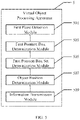
- FIG. 1 is a schematic flowchart illustrating a virtual object processing method according to an exemplary embodiment of the present disclosure.
- the method illustrated in FIG. 1 can be implemented by a first device, where the first device is a device that initially configures a virtual object. That is, after configuring the virtual object, the first device may transmit the virtual object and its position to another device.
- a second device can be a device that receives information on the virtual object.
- the first device can be an initiator of a multi-person AR interaction. It is easy to understand that in other instances, the second device may also be an initiator of a multi-person AR interaction. That is, an electronic device can be a device that initially configures a virtual object or a device that receives information on a virtual object, or a device that initially configures a virtual object and receives information on another virtual object.
- the virtual object processing method may include the following steps.
- a spatial plane in a scene where a first device is located is detected.
- the first device can collect a plurality of video frame images for the scene, and inertial information corresponding to the images.
- the video frame image may be visual information collected by a camera of the first device.
- the inertial information may be obtained by means of an Inertial Measurement Unit (IMU) device of the first device.
- the IMU device may include a gyroscope and an accelerometer, which can measure an angular velocity and an acceleration of a terminal device respectively. Since the operating frequency of the IMU device is usually higher than the frequency at which the camera collects images, the IMU pre-integration method can be used to evaluate the inertial information of the corresponding frame.
- the IMU pre-integration is a time-based integration, and can be used to obtain the inertial information such as the position, speed, and rotation angle corresponding to two images.
- the feature point cloud in the present disclosure is usually a sparse feature point cloud in order to facilitate calculation and fast processing.
- a semi-dense feature point cloud and a dense feature point cloud can alternatively be used as the feature point cloud constructed in the present disclosure.
- the constructed feature point cloud can be used to detect a spatial plane in the scene.
- the feature point cloud can be divided into triangular facets, normal vectors of respective triangular facets can be determined, a clustering may be performed on respective normal vectors, and then a spatial plane in the scene can be determined based on the result of clustering.
- a 3D Hough plane detection algorithm can be used to detect the feature point cloud to determine a spatial plane in the scene where the first device is located.
- the specific process of detecting the spatial plane is not particularly limited in this exemplary embodiment.
- the spatial plane can be represented by a normal vector or a coordinate point in the plane.
- real objects in the scene are detected to determine a plurality of real object position boxes.
- a current frame image taken by the first device can be obtained and used as a target frame image.
- the target frame image can be input into a trained machine learning model, and the trained machine learning model can be used to determine a plurality of real object position boxes.
- the machine learning model used in the present disclosure is a deep learning model for target detection, for example a MobileNet model.
- the present disclosure does not impose special restrictions on the network structure and training process of the model.
- those skilled in the art can determine that other models can also be used to achieve target detection.
- any of some convolutional neural networks that output multiple classification results can be used as the machine learning model described in the present disclosure.
- the solutions of applying this processing means to the virtual object processing method of the present disclosure all belong to the concept of the present disclosure.
- the position box described in the present disclosure is usually a rectangular box.
- the determined position box can be regarded as a 2D rectangular bounding box (2D box).
- the position box can also be in another shape, such as a triangular, circular, other polygonal shape, etc., which is not particularly limited in this exemplary embodiment.
- the real object position box described in the present disclosure refers to a position box containing a real object.
- the real object may be an object including a plane and actually existing in the scene, such as a table, a coffee table, a TV, a chair, and so on.
- a candidate position box set is determined from the plurality of real object position boxes.
- a matching relation between the plurality of real object position boxes and the spatial plane in the scene can be determined at step 106.
- a plurality of feature position points of the real object position box can be determined first.
- the feature position points may be position points (or called coordinate points) corresponding to four corners of the rectangular box. It is easy to understand that for a triangular box, the feature position points described herein may refer to the position points corresponding to three corners of the triangular box.
- the plurality of feature position points can be converted onto a coordinate system of the feature point cloud. Since the real object position box is a two-dimensional box, it is necessary to map the two-dimensional coordinates of the plurality of feature position points onto a three-dimensional coordinate system of the feature point cloud, so as to determine the coordinate points in the coordinate system of the feature point cloud.
- normal directions of the plurality of feature position points of the real object position box are determined. Specifically, a plane of the real object position box in the three-dimensional coordinate system of the feature point cloud is determined, and a direction perpendicular to the plane is determined as a normal direction of the real object position box. and in this case, the normal direction can be used as the normal direction of each of the plurality of feature position points of the real object position box.
- the real object position box is determined as a candidate position box, and the real object position box is added to the candidate position box set. At this time, it can be determined that the real object position box matches the spatial plane.
- the determined candidate position box set usually includes a plurality of candidate position boxes.
- the candidate position box set may include only one candidate position box.
- position information of a virtual object in the target position box is determined.
- the virtual object described in the present disclosure may be an object used for AR interaction.
- the virtual object is related to a specific AR scene.
- it may be a leather ball, a chess piece of a board game, a presentation interface, a cartoon character, etc..
- the type of the virtual object is not specifically limited in the present disclosure.
- the candidate position box in the candidate position box set may be displayed on a screen of the device for selection by a user.
- the candidate position box in the candidate position box set may alternatively not be displayed, the user can determine a possible position for placing the virtual object based on his own vision. In this case, only when the position determined by the user is same as the position of a candidate position box in the determined candidate position box set, the first device can make a response.
- the user can perform a virtual object configuration operation on a target position box in the candidate position box set. For example, the user can click on one candidate position box. In addition, when there are a plurality of alternative virtual objects, the user can select one virtual object for configuration.
- the candidate position box is the target position box.
- the position of a touch point where the user clicks the target position frame can be determined as the position of the virtual object in the target position box.
- the user click operation described in the present disclosure may include a short press, a long press and other operations.
- the position information of the virtual object in the target position box may be characterized by, for example, a center coordinate point of the virtual object.
- a three-dimensional position information of the virtual object in the scene (the feature point cloud) can be determined, and the virtual object can be displayed on the first device based on the three-dimensional position information.
- information on the virtual object and the position information of the virtual object in the target position box are transmitted to a second device for displaying the virtual object on the second device.
- the first device may transmit information on the virtual object and the position information of the virtual object in the target position box to a second device.
- the information on the virtual object may be information that uniquely identifies the virtual object, or may be information that describes the virtual object. That is, the second device can uniquely and indiscriminately determine the virtual object based on the information on the virtual object to display the virtual object.
- the display position of the virtual object in the second device is related to the position information of the virtual object in the target position box of the first device. That is, based on the position information of the virtual object in the target position box of the first device in combination with a user operation on the second device, the position of the virtual object in the second device can be determined.
- the first device can also transmit the information on the virtual object and the position information of the virtual object in the target position box to other devices besides the second device, so as to realize AR interaction among more than two devices.
- a virtual object processing method for the second device will be described below.
- FIG. 2 is a schematic flowchart illustrating a virtual object processing method according to another exemplary embodiment of the present disclosure. The method illustrated in FIG. 2 can be implemented by the second device.
- the virtual object processing method corresponding to the second device may include the following steps.
- a spatial plane in a scene where a second device is located is detected.
- feature points of the scene where the second device is located are extracted based on a plurality of video frame images and corresponding inertial information that are collected by the second device.
- a feature point cloud is constructed based on the extracted feature points.
- the spatial plane in the scene where the second device is located is detected by use of the feature point cloud.
- step 102 The specific process is similar to the process of step 102, and details thereof will be omitted here.
- real objects in the scene are detected to determine a plurality of real object position boxes.
- a current frame image taken by the second device can be used as a target frame image.
- the target frame image is input into a trained machine learning model.
- the plurality of real object position boxes are determined by use of the trained machine learning model.
- step 104 The specific process is similar to the process of step 104, and details thereof will be omitted here.
- a candidate position box set is determined from the plurality of real object position boxes.
- a plurality of feature position points of the real object position box are determined.
- coordinate points and normal directions of the plurality of feature position points in a coordinate system of the feature point cloud of the scene where the second device is located are determined.
- the real object position box is determined as a candidate position box, and the real object position box is added to the candidate position box set.
- step 106 The specific process is similar to the process of step 106, and details thereof will be omitted here.
- information on a virtual object and position information of the virtual object in a target position box of a first device that are transmitted by the first device are obtained.
- the second device can obtain information on a virtual object and the position information of the virtual object in the target position box of the first device that are transmitted by the first device.
- a virtual object placement box is determined from the candidate position box set.
- the user of the second device may determine a position box from the candidate position box set as a virtual object placement box. Similarly, a candidate position box in the candidate position box set can be displayed on the second device for selection by the user.
- the method of the present disclosure may alternatively perform step 210 first, and then perform step 208.
- position information of the virtual object in the virtual object placement box is determined for displaying the virtual object on the second device.
- a size ratio between the target position box and the virtual object position box may be determined first. For example, when the size of the target position box transmitted by the first device is 10 ⁇ 10 and the size of the virtual object position box in the second device is 5 ⁇ 5, the size ratio is 2:1.
- the second device may perform a zooming processing on the position information of the virtual object in the target position box of the first device based on the size ratio, and determine the result of the zooming processing as the position information of the virtual object in the virtual object placement box. That is, if the virtual object is in the exact center of the target position box, the virtual object is also in the exact center of the virtual object position box.
- the position of the virtual object in the virtual object position box can be determined according to an equal proportional zooming process of the two-dimensional coordinate system. Taking a rectangular box as an example, any one of the four corners can be used as the coordinate origin to construct a rectangular coordinate system, so as to determine a specific position of the virtual object in the virtual object position box by use of the rectangular coordinate system. It should be noted that the zooming processing is only for position information, and the size of the virtual object usually does not change.
- the first device 31 may determine a plurality of candidate position boxes. As shown in the figure, each candidate position box is a rectangular box. A user of the first device 31 determines a target position box 311, and a position of the virtual object in the first device 31 is a position 310. The first device 31 transmits the position information of the position 310 in the target position box 311 to the second device 32.
- a user of the second device 32 selects a virtual object placement box 321 from a plurality of candidate position boxes.
- the virtual object can be placed at a position 320 of the virtual object placement box 321.
- the position of the position 310 in the target position box 311 is consistent with the position of the position 320 in the virtual object placement box 321.
- the second device can determine three-dimensional position information of the virtual object in the scene where the second device is located based on the position information. Based on the three-dimensional position information of the virtual object in the scene, the virtual object can be displayed on the second device.
- the second device can transmit data of the interaction operation to the first device in response to an interaction operation of the user of the second device on the virtual object.
- the first device can display an image corresponding to the interaction operation.
- the user of the second device may use AR interaction means (for example, by means of gestures) to rotate the virtual object, and the virtual object will present a rotating effect on the first device.
- a processing procedure of an exemplary virtual object processing method of the present disclosure will be described below with reference to FIG. 4 .
- a first device For a first device: at step 402, collected visual information and inertial information can be used to construct a sparse feature point cloud; at step 404, a spatial plane in a scene can be detected based on the constructed sparse feature point cloud; at step 406, a target detection is performed on the scene to determine a plurality of real object position boxes; at step 408, a candidate position box set is determined based on a matching relation between the plurality of real object position boxes and the spatial plane in the scene; and at step 410, in response to an operation of a user of the first device, a position of a virtual object is determined, and information on the virtual object and position information of the virtual object in a position box are transmitted to a second device.
- step 412 to step 418 are similar to the processes from step 402 to step 408, and details thereof will be omitted here.
- step 420 based on the position information of the virtual object of the first device in the position box and a user operation of the second device, a display position of the virtual object in the second device is determined, and the virtual object is displayed.
- a user of the second device can perform an operation on the virtual object and transmit data on the operation to the first device.
- the first device may display the process of the operation of the user of the second device on the virtual object, and may further respond to the operation of the user of the first device to implement AR interaction between the first device and the second device.
- the exemplary method of the present disclosure can realize AR interaction among devices in different environments, which eliminates the limitation brought by the scene and broadens the range of application of multi-person AR technology; on another hand, since the scenes are not required to be the same, it can realize remote or offsite multi-person AR interaction; on another hand, the method of the present disclosure can be directly implemented by a mobile device, without the need for specially configured labeling apparatuses, auxiliary devices and the like for realizing the AR process, which reduces costs; on another hand, the first device and the second device have similar processing procedures in determining the candidate position box set, and the algorithms can be configured in advance and adapted to various mobile devices to implement the AR interaction process among two or more devices.
- an exemplary embodiment further provides a virtual object processing apparatus.
- Fig. 5 is a schematic block diagram of a virtual object processing apparatus according to an exemplary embodiment of the present disclosure.
- a virtual object processing apparatus 5 may include a first plane detection module 501, a first position box determination module 503, a first position box set determination module 505, an object position determination module 507, and an information transmission module 509.
- the first plane detection module 501 may be configured to detect a spatial plane in a scene where a first device is located.
- the first position box determination module 503 may be configured to detect real objects in the scene to determine a plurality of real object position boxes.
- the first position box set determination module 505 may be configured to determine a candidate position box set from the plurality of real object position boxes based on a matching relation between the plurality of real object position boxes and the spatial plane in the scene.
- the object position determination module 507 may be configured to determine position information of a virtual object in the target position box in response to a virtual object configuration operation for a target position box in the candidate position box set.
- the information transmission module 509 may be configured to transmit the information on the virtual object and the position information of the virtual object in the target position box to a second device for displaying the virtual object on the second device.
- the first plane detection module 501 may be configured to: extract feature points of the scene based on a plurality of video frame images and corresponding inertial information that are collected by the first device; construct a feature point cloud based on the extracted feature points; and detect the spatial plane in the scene where the first device is located by use of the feature point cloud.
- the first position box determination module 503 may be configured to determine a target frame image, input the target frame image into a trained machine learning model, and determine a plurality of real object position boxes by use of the trained machine learning model.
- the first position box set determination module 505 may be configured to: determine, for any one real object position box of the plurality of real object position boxes, a plurality of feature position points of the real object position box; determine coordinate points and normal directions of the plurality of feature position points in a coordinate system of the feature point cloud; and determine the real object position box as a candidate position box and add the real object position box to the candidate position box set, when projections of the coordinate points of the plurality of feature position points in the coordinate system of the feature point cloud along the respective normal directions are all on a same spatial plane.
- the object position determination module 507 may be further configured to: determine, after determining the position information of the virtual object in the target position box, three-dimensional position information of the virtual object in the scene based on the position information of the virtual object in the target position box; and display the virtual object on the first device based on the three-dimensional position information of the virtual object in the scene.
- a virtual object processing apparatus 6 may include a second plane detection module 601, a second position box determination module 603, a second position box set determination module 605, an information obtaining module 607, a placement box determination module 609 and a position conversion module 611.
- the second plane detection module 601 may be configured to detect a spatial plane in a scene where a second device is located.
- the second position box determination module 603 may be configured to detect real objects in the scene to determine a plurality of real object position boxes.
- the second position box set determination module 605 may be configured to determine a candidate position box set from the plurality of real object position boxes based on a matching relation between the plurality of real object position boxes and the spatial plane in the scene.
- the information obtaining module 607 may be configured to obtain information on a virtual object and position information of the virtual object in a target position box of the first device that are transmitted by the first device.
- the placement box determination module 609 may be configured to determine a virtual object placement box from the candidate position box set in response to a virtual object configuration operation.
- the position conversion module 611 may be configured to determine position information of the virtual object in the virtual object placement box based on the position information of the virtual object in the target position box of the first device for displaying the virtual object on the second device.
- the second plane detection module 601 may be configured to: extract feature points of the scene based on a plurality of video frame images and corresponding inertial information that are collected by the second device; construct a feature point cloud based on the extracted feature points; and detect the spatial plane in the scene where the second device is located by use of the feature point cloud.
- the second position box determination module 603 may be configured to determine a target frame image, input the target frame image into a trained machine learning model, and determine a plurality of real object position boxes by use of the trained machine learning model.
- the second position box set determination module 605 may be configured to determine, for any one real object position box in the plurality of real object position boxes, a plurality of feature position points of the real object position box; determine coordinate points and normal directions of the plurality of feature position points in a coordinate system of the feature point cloud; and determine the real object position box as a candidate position box and add the real object position box to the candidate position box set, when projections of the coordinate points of the plurality of feature position points in the coordinate system of the feature point cloud along the respective normal directions are all on a same spatial plane.
- the position conversion module 611 may be configured to determine a size ratio between the target position box and the virtual object position box; perform a zooming processing on the position information of the virtual object in the target position box of the first device based on the size ratio, and determine a result of the zooming processing as the position information of the virtual object in the virtual object placement box.
- the position conversion module 611 may be further configured to determine three-dimensional position information of the virtual object in the scene based on the position information of the virtual object in the virtual object placement box; and display the virtual object on the second device based on the three-dimensional position information of the virtual object in the scene.
- the virtual object processing apparatus 7 may further include an interaction processing module 701.
- the interaction processing module 701 may be configured to transmit, after displaying the virtual object on the second device, in response to an interaction operation on the virtual object, data on the interaction operation to the first device for displaying an image corresponding to the interaction operation on the first device.
- a computer-readable storage medium stores a program product capable of implementing any of the above-mentioned methods in this specification.
- various aspects of the present disclosure may also be implemented in the form of a program product which includes program codes.
- the program codes are configured to, when the program product runs on a terminal device, cause the terminal device to perform the steps of the "exemplary method" described above in this specification according to various exemplary embodiments of the present disclosure.
- the program product for implementing the above method according to the embodiment of the present disclosure may adopt a portable compact disk read-only memory (CD-ROM), may include program codes, and may run on a terminal device such as a personal computer.
- CD-ROM portable compact disk read-only memory
- the program product of the present disclosure is not limited thereto.
- the readable storage medium can be any tangible medium that contains or stores a program, and the program can be used by or in combination with an instruction execution system, apparatus, or device.
- the program product can use any combination of one or more readable media.
- the readable medium may be a readable signal medium or a readable storage medium.
- the readable storage medium may be, for example, but not limited to, an electrical, magnetic, optical, electromagnetic, infrared, or semi-conductive system, apparatus, or device, or any combination thereof. More specific examples (non-exhaustive list) of the readable storage medium include: electrical connections with one or more wires, portable disks, hard disks, random access memories (RAMs), read-only memories (ROMs), erasable programmable read-only memory (EPROMs or flash memories), optical disks, portable compact disk read-only memories (CD-ROMs), optical storage devices, magnetic storage devices, or any suitable combination thereof.
- the computer-readable signal medium may include a data signal propagated in baseband or as a part of a carrier wave, and carries readable program codes therein.
- the propagated data signal can be in many forms, including but not limited to electromagnetic signals, optical signals, or any suitable combination thereof.
- the readable signal medium may also be any readable medium other than a readable storage medium, and the readable medium can transmit, propagate, or transfer programs used by or in combination with an instruction execution system, apparatus, or device.
- the program codes contained in the readable medium can be transmitted by any suitable medium, including but not limited to wireless, wired, optical cable, RF, etc., or any suitable combination thereof.
- the program codes used to perform the operations of the present disclosure can be written in any combination of one or more programming languages.
- the programming languages include object-oriented programming languages such as Java, C++, etc., as well as conventional procedural programming language such as "C" language or a similar programming language.
- the program codes can be executed entirely on a user computing device, executed partly on a user device, executed as a standalone software package, executed partly on the user computing device and partly on a remote computing device, or executed entirely on the remote computing device or on a server.
- the remote computing device can be connected to a user computing device through any kind of network, including a local area network (LAN) or a wide area network (WAN), or can be connected (for example, connected via the internet provided by an internet service provider) to an external computing device.
- LAN local area network
- WAN wide area network
- an electronic device capable of implementing any of the above methods is also provided.
- any of various aspects of the present disclosure can be implemented as a system, a method, or a program product. Therefore, any of various aspects of the present disclosure can be specifically implemented in any of the following forms, namely: a complete hardware implementation, a complete software implementation (including firmware, microcode, etc.), or a combination of hardware aspect and software aspect implementation, all of which may be collectively referred to herein as a "circuit", "module” or "system”.
- the electronic device 800 according to such an embodiment of the present disclosure will be described below with reference to FIG. 8 .
- the electronic device 800 shown in FIG. 8 is only an example, and should not bring any limitation to the functions and scope of use of the embodiments of the present disclosure.
- the electronic device 800 is represented in the form of a general-purpose computing device.
- Components of the electronic device 800 may include, but are not limited to: at least one processing unit 810 described above, at least one storage unit 820 described above, a bus 830 configured to connect different system components (including the storage unit 820 and the processing unit 810), and a display unit 840.
- the storage unit stores program codes, and the program codes can be executed by the processing unit 810 to cause the processing unit 810 to perform the steps of the "exemplary method" described above in this specification according to the various exemplary embodiments of the present disclosure.
- the processing unit 810 may perform step 102 to step 110 as illustrated in FIG. 1 and/or may perform step 202 to step 212 as illustrated in FIG. 2 .
- the storage unit 820 may include a readable medium in the form of a transitory storage unit, such as a random access storage unit (RAM) 8201 and/or a cache unit 8202, and may further include a read-only storage unit (ROM) 8203.
- RAM random access storage unit
- ROM read-only storage unit
- the storage unit 820 may further include a program/utility tool 8204 having a set of program modules 8205, i.e., at least one program module 8205.
- program module 8205 includes but is not limited to: an operating system, one or more application programs, other program modules, and program data. Each or some combination of these examples may include the implementation of a network environment.
- the bus 830 may include one or more of several types of bus structures, including a storage unit bus, a storage unit controller, a peripheral bus, a graphics acceleration port, a processing unit, or a local area bus using any of multiple bus structures.
- the electronic device 800 may also communicate with one or more external devices 900 (such as keyboards, pointing devices, Bluetooth devices, etc.), and may also communicate with one or more devices that enable a user to interact with the electronic device 800, and/or communicate with any device (e.g., a router, a modem, etc.) that enables the electronic device 800 to communicate with one or more other computing devices. Such a communication can be performed through an input/output (I/O) interface 850.
- the electronic device 800 may also communicate with one or more networks (for example, a local area network (LAN), a wide area network (WAN), and/or a public network, such as the Internet) through a network adapter 860.
- networks for example, a local area network (LAN), a wide area network (WAN), and/or a public network, such as the Internet
- the network adapter 860 communicates with other modules of the electronic device 800 through the bus 830. It should be understood that although not illustrated in the figure, other hardware and/or software modules can be used in conjunction with the electronic device 800, including but not limited to: microcodes, device drivers, redundant processing units, external disk drive arrays, Redundant Array of Independent Disk (RAID) systems, tape drives and data backup storage system, etc.
- RAID Redundant Array of Independent Disk
- the technical solutions according to the embodiments of the present disclosure can be embodied in the form of a software product which can be stored in a non-transitory storage medium (which can be a CD-ROM, U disk, mobile hard disk, etc.) or on the network, and include several instructions to cause a computing device (which can be a personal computer, a server, a terminal device, or a network device, etc.) to perform the method according to any of the embodiments of the present disclosure.
- a computing device which can be a personal computer, a server, a terminal device, or a network device, etc.
- modules or units of the device for action execution are mentioned in the above detailed description, this division is not mandatory.
- the features and functions of two or more modules or units described above may be embodied in one module or unit.
- the features and functions of a module or unit described above can be further divided into multiple modules or units to be embodied.
Applications Claiming Priority (2)
| Application Number | Priority Date | Filing Date | Title |
|---|---|---|---|
| CN201910695983.8A CN110473293B (zh) | 2019-07-30 | 2019-07-30 | 虚拟对象处理方法及装置、存储介质和电子设备 |
| PCT/CN2020/105578 WO2021018214A1 (fr) | 2019-07-30 | 2020-07-29 | Procédé et appareil de traitement d'objet virtuel, et support de stockage et dispositif électronique |
Publications (2)
| Publication Number | Publication Date |
|---|---|
| EP4006847A1 true EP4006847A1 (fr) | 2022-06-01 |
| EP4006847A4 EP4006847A4 (fr) | 2022-10-26 |
Family
ID=68509179
Family Applications (1)
| Application Number | Title | Priority Date | Filing Date |
|---|---|---|---|
| EP20845989.1A Pending EP4006847A4 (fr) | 2019-07-30 | 2020-07-29 | Procédé et appareil de traitement d'objet virtuel, et support de stockage et dispositif électronique |
Country Status (4)
| Country | Link |
|---|---|
| US (1) | US11893702B2 (fr) |
| EP (1) | EP4006847A4 (fr) |
| CN (1) | CN110473293B (fr) |
| WO (1) | WO2021018214A1 (fr) |
Families Citing this family (8)
| Publication number | Priority date | Publication date | Assignee | Title |
|---|---|---|---|---|
| CN110473293B (zh) * | 2019-07-30 | 2023-03-24 | Oppo广东移动通信有限公司 | 虚拟对象处理方法及装置、存储介质和电子设备 |
| CN112306243A (zh) * | 2020-11-19 | 2021-02-02 | 深圳前海微众银行股份有限公司 | 数据处理方法、装置、设备及存储介质 |
| US11741676B2 (en) | 2021-01-21 | 2023-08-29 | Samsung Electronics Co., Ltd. | System and method for target plane detection and space estimation |
| CN112784002B (zh) * | 2021-02-07 | 2023-09-26 | 腾讯科技(深圳)有限公司 | 一种虚拟场景生成方法、装置、设备和存储介质 |
| US11657569B1 (en) * | 2021-07-13 | 2023-05-23 | All Tingz Co. | Method for creating a tangible objection and digitizing the tangible object using an artificial intelligence process |
| CN113838217B (zh) * | 2021-09-23 | 2023-09-12 | 北京百度网讯科技有限公司 | 信息展示方法、装置、电子设备及可读存储介质 |
| CN117055996A (zh) * | 2023-08-07 | 2023-11-14 | 香港科技大学(广州) | 虚拟场景界面显示方法、装置、设备及存储介质 |
| CN117635888B (zh) * | 2023-12-07 | 2024-04-26 | 腾讯科技(深圳)有限公司 | 一种数据处理方法及相关装置 |
Family Cites Families (17)
| Publication number | Priority date | Publication date | Assignee | Title |
|---|---|---|---|---|
| US9911231B2 (en) * | 2013-10-08 | 2018-03-06 | Samsung Electronics Co., Ltd. | Method and computing device for providing augmented reality |
| US10360729B2 (en) | 2015-04-06 | 2019-07-23 | Scope Technologies Us Inc. | Methods and apparatus for augmented reality applications |
| US10169917B2 (en) * | 2015-08-20 | 2019-01-01 | Microsoft Technology Licensing, Llc | Augmented reality |
| CN106200944A (zh) * | 2016-06-30 | 2016-12-07 | 联想(北京)有限公司 | 一种对象的控制方法、控制装置和控制系统 |
| CN106997281A (zh) * | 2017-04-10 | 2017-08-01 | 北京小米移动软件有限公司 | 共享虚拟对象的方法及智能设备 |
| CN110036359B (zh) * | 2017-06-23 | 2022-08-26 | 杰创科虚拟现实有限公司 | 第一人称角色扮演互动式增强现实 |
| CN107390875B (zh) * | 2017-07-28 | 2020-01-31 | 腾讯科技(上海)有限公司 | 信息处理方法、装置、终端设备和计算机可读存储介质 |
| CN107393017A (zh) * | 2017-08-11 | 2017-11-24 | 北京铂石空间科技有限公司 | 图像处理方法、装置、电子设备及存储介质 |
| CN109840947B (zh) * | 2017-11-28 | 2023-05-09 | 广州腾讯科技有限公司 | 增强现实场景的实现方法、装置、设备及存储介质 |
| CN108830894B (zh) | 2018-06-19 | 2020-01-17 | 亮风台(上海)信息科技有限公司 | 基于增强现实的远程指导方法、装置、终端和存储介质 |
| WO2020056692A1 (fr) | 2018-09-20 | 2020-03-26 | 太平洋未来科技(深圳)有限公司 | Procédé et appareil d'interaction d'informations et dispositif électronique |
| CN109754471B (zh) * | 2019-01-10 | 2023-06-27 | 网易(杭州)网络有限公司 | 增强现实中的图像处理方法及装置、存储介质、电子设备 |
| CN109903129A (zh) * | 2019-02-18 | 2019-06-18 | 北京三快在线科技有限公司 | 增强现实显示方法与装置、电子设备、存储介质 |
| CN109847361B (zh) | 2019-02-27 | 2020-11-10 | 腾讯科技(深圳)有限公司 | 运动状态的同步方法和装置、存储介质、电子装置 |
| CN109992108B (zh) * | 2019-03-08 | 2020-09-04 | 北京邮电大学 | 多用户交互的增强现实方法及系统 |
| CN110473293B (zh) * | 2019-07-30 | 2023-03-24 | Oppo广东移动通信有限公司 | 虚拟对象处理方法及装置、存储介质和电子设备 |
| US11120639B1 (en) * | 2020-04-24 | 2021-09-14 | Microsoft Technology Licensing, Llc | Projecting telemetry data to visualization models |
-
2019
- 2019-07-30 CN CN201910695983.8A patent/CN110473293B/zh active Active
-
2020
- 2020-07-29 WO PCT/CN2020/105578 patent/WO2021018214A1/fr unknown
- 2020-07-29 EP EP20845989.1A patent/EP4006847A4/fr active Pending
-
2022
- 2022-01-27 US US17/586,617 patent/US11893702B2/en active Active
Also Published As
| Publication number | Publication date |
|---|---|
| CN110473293A (zh) | 2019-11-19 |
| US20220148279A1 (en) | 2022-05-12 |
| EP4006847A4 (fr) | 2022-10-26 |
| US11893702B2 (en) | 2024-02-06 |
| WO2021018214A1 (fr) | 2021-02-04 |
| CN110473293B (zh) | 2023-03-24 |
Similar Documents
| Publication | Publication Date | Title |
|---|---|---|
| US11893702B2 (en) | Virtual object processing method and apparatus, and storage medium and electronic device | |
| US11394950B2 (en) | Augmented reality-based remote guidance method and apparatus, terminal, and storage medium | |
| US10732725B2 (en) | Method and apparatus of interactive display based on gesture recognition | |
| AU2020202551B2 (en) | Method for representing points of interest in a view of a real environment on a mobile device and mobile device therefor | |
| US11625841B2 (en) | Localization and tracking method and platform, head-mounted display system, and computer-readable storage medium | |
| US9591295B2 (en) | Approaches for simulating three-dimensional views | |
| US9224237B2 (en) | Simulating three-dimensional views using planes of content | |
| US9437038B1 (en) | Simulating three-dimensional views using depth relationships among planes of content | |
| US11231845B2 (en) | Display adaptation method and apparatus for application, and storage medium | |
| CN110322500A (zh) | 即时定位与地图构建的优化方法及装置、介质和电子设备 | |
| US9268410B2 (en) | Image processing device, image processing method, and program | |
| CN110457414A (zh) | 离线地图处理、虚拟对象显示方法、装置、介质和设备 | |
| TW201346640A (zh) | 影像處理裝置及電腦程式產品 | |
| US20130155026A1 (en) | New kind of multi-touch input device | |
| EP4105766A1 (fr) | Procédé et appareil d'affichage d'image, et dispositif informatique et support de stockage | |
| US11561651B2 (en) | Virtual paintbrush implementing method and apparatus, and computer readable storage medium | |
| US11080943B2 (en) | Method and apparatus for displaying with 3D parallax effect | |
| CN109992111B (zh) | 增强现实扩展方法和电子设备 | |
| CN113934297A (zh) | 一种基于增强现实的交互方法、装置、电子设备及介质 | |
| CN109857244B (zh) | 一种手势识别方法、装置、终端设备、存储介质及vr眼镜 | |
| CN117453037A (zh) | 交互方法、头显设备、电子设备及可读存储介质 | |
| CN117008774A (zh) | 窗口控制方法、装置和存储介质及电子设备 | |
| CN114119737A (zh) | 室内导航的视觉定位方法及相关设备 | |
| CN117991967A (zh) | 虚拟键盘交互方法、装置、设备、存储介质和程序产品 | |
| CN112817447A (zh) | 一种ar内容显示方法及系统 |
Legal Events
| Date | Code | Title | Description |
|---|---|---|---|
| STAA | Information on the status of an ep patent application or granted ep patent |
Free format text: STATUS: THE INTERNATIONAL PUBLICATION HAS BEEN MADE |
|
| PUAI | Public reference made under article 153(3) epc to a published international application that has entered the european phase |
Free format text: ORIGINAL CODE: 0009012 |
|
| STAA | Information on the status of an ep patent application or granted ep patent |
Free format text: STATUS: REQUEST FOR EXAMINATION WAS MADE |
|
| 17P | Request for examination filed |
Effective date: 20220224 |
|
| AK | Designated contracting states |
Kind code of ref document: A1 Designated state(s): AL AT BE BG CH CY CZ DE DK EE ES FI FR GB GR HR HU IE IS IT LI LT LU LV MC MK MT NL NO PL PT RO RS SE SI SK SM TR |
|
| A4 | Supplementary search report drawn up and despatched |
Effective date: 20220927 |
|
| RIC1 | Information provided on ipc code assigned before grant |
Ipc: G06T 11/00 20060101ALI20220921BHEP Ipc: G06T 19/00 20110101AFI20220921BHEP |
|
| DAV | Request for validation of the european patent (deleted) | ||
| DAX | Request for extension of the european patent (deleted) |