EP4006685B1 - Mischventil und heiz- oder kühlsystem - Google Patents
Mischventil und heiz- oder kühlsystem Download PDFInfo
- Publication number
- EP4006685B1 EP4006685B1 EP20209825.7A EP20209825A EP4006685B1 EP 4006685 B1 EP4006685 B1 EP 4006685B1 EP 20209825 A EP20209825 A EP 20209825A EP 4006685 B1 EP4006685 B1 EP 4006685B1
- Authority
- EP
- European Patent Office
- Prior art keywords
- inlet port
- obstruction
- mixing valve
- valve
- port
- Prior art date
- Legal status (The legal status is an assumption and is not a legal conclusion. Google has not performed a legal analysis and makes no representation as to the accuracy of the status listed.)
- Active
Links
Images


Classifications
-
- G—PHYSICS
- G05—CONTROLLING; REGULATING
- G05D—SYSTEMS FOR CONTROLLING OR REGULATING NON-ELECTRIC VARIABLES
- G05D23/00—Control of temperature
- G05D23/01—Control of temperature without auxiliary power
- G05D23/13—Control of temperature without auxiliary power by varying the mixing ratio of two fluids having different temperatures
- G05D23/1393—Control of temperature without auxiliary power by varying the mixing ratio of two fluids having different temperatures characterised by the use of electric means
-
- F—MECHANICAL ENGINEERING; LIGHTING; HEATING; WEAPONS; BLASTING
- F16—ENGINEERING ELEMENTS AND UNITS; GENERAL MEASURES FOR PRODUCING AND MAINTAINING EFFECTIVE FUNCTIONING OF MACHINES OR INSTALLATIONS; THERMAL INSULATION IN GENERAL
- F16K—VALVES; TAPS; COCKS; ACTUATING-FLOATS; DEVICES FOR VENTING OR AERATING
- F16K11/00—Multiple-way valves, e.g. mixing valves; Pipe fittings incorporating such valves
- F16K11/02—Multiple-way valves, e.g. mixing valves; Pipe fittings incorporating such valves with all movable sealing faces moving as one unit
- F16K11/06—Multiple-way valves, e.g. mixing valves; Pipe fittings incorporating such valves with all movable sealing faces moving as one unit comprising only sliding valves, i.e. sliding closure elements
- F16K11/078—Multiple-way valves, e.g. mixing valves; Pipe fittings incorporating such valves with all movable sealing faces moving as one unit comprising only sliding valves, i.e. sliding closure elements with pivoted and linearly movable closure members
-
- F—MECHANICAL ENGINEERING; LIGHTING; HEATING; WEAPONS; BLASTING
- F16—ENGINEERING ELEMENTS AND UNITS; GENERAL MEASURES FOR PRODUCING AND MAINTAINING EFFECTIVE FUNCTIONING OF MACHINES OR INSTALLATIONS; THERMAL INSULATION IN GENERAL
- F16K—VALVES; TAPS; COCKS; ACTUATING-FLOATS; DEVICES FOR VENTING OR AERATING
- F16K11/00—Multiple-way valves, e.g. mixing valves; Pipe fittings incorporating such valves
- F16K11/02—Multiple-way valves, e.g. mixing valves; Pipe fittings incorporating such valves with all movable sealing faces moving as one unit
- F16K11/08—Multiple-way valves, e.g. mixing valves; Pipe fittings incorporating such valves with all movable sealing faces moving as one unit comprising only taps or cocks
- F16K11/087—Multiple-way valves, e.g. mixing valves; Pipe fittings incorporating such valves with all movable sealing faces moving as one unit comprising only taps or cocks with spherical plug
- F16K11/0873—Multiple-way valves, e.g. mixing valves; Pipe fittings incorporating such valves with all movable sealing faces moving as one unit comprising only taps or cocks with spherical plug the plug being only rotatable around one spindle
-
- F—MECHANICAL ENGINEERING; LIGHTING; HEATING; WEAPONS; BLASTING
- F16—ENGINEERING ELEMENTS AND UNITS; GENERAL MEASURES FOR PRODUCING AND MAINTAINING EFFECTIVE FUNCTIONING OF MACHINES OR INSTALLATIONS; THERMAL INSULATION IN GENERAL
- F16K—VALVES; TAPS; COCKS; ACTUATING-FLOATS; DEVICES FOR VENTING OR AERATING
- F16K27/00—Construction of housing; Use of materials therefor
- F16K27/06—Construction of housing; Use of materials therefor of taps or cocks
- F16K27/067—Construction of housing; Use of materials therefor of taps or cocks with spherical plugs
-
- F—MECHANICAL ENGINEERING; LIGHTING; HEATING; WEAPONS; BLASTING
- F16—ENGINEERING ELEMENTS AND UNITS; GENERAL MEASURES FOR PRODUCING AND MAINTAINING EFFECTIVE FUNCTIONING OF MACHINES OR INSTALLATIONS; THERMAL INSULATION IN GENERAL
- F16K—VALVES; TAPS; COCKS; ACTUATING-FLOATS; DEVICES FOR VENTING OR AERATING
- F16K31/00—Actuating devices; Operating means; Releasing devices
- F16K31/02—Actuating devices; Operating means; Releasing devices electric; magnetic
- F16K31/04—Actuating devices; Operating means; Releasing devices electric; magnetic using a motor
- F16K31/041—Actuating devices; Operating means; Releasing devices electric; magnetic using a motor for rotating valves
-
- F—MECHANICAL ENGINEERING; LIGHTING; HEATING; WEAPONS; BLASTING
- F16—ENGINEERING ELEMENTS AND UNITS; GENERAL MEASURES FOR PRODUCING AND MAINTAINING EFFECTIVE FUNCTIONING OF MACHINES OR INSTALLATIONS; THERMAL INSULATION IN GENERAL
- F16K—VALVES; TAPS; COCKS; ACTUATING-FLOATS; DEVICES FOR VENTING OR AERATING
- F16K37/00—Special means in or on valves or other cut-off apparatus for indicating or recording operation thereof, or for enabling an alarm to be given
- F16K37/0025—Electrical or magnetic means
- F16K37/005—Electrical or magnetic means for measuring fluid parameters
-
- F—MECHANICAL ENGINEERING; LIGHTING; HEATING; WEAPONS; BLASTING
- F16—ENGINEERING ELEMENTS AND UNITS; GENERAL MEASURES FOR PRODUCING AND MAINTAINING EFFECTIVE FUNCTIONING OF MACHINES OR INSTALLATIONS; THERMAL INSULATION IN GENERAL
- F16K—VALVES; TAPS; COCKS; ACTUATING-FLOATS; DEVICES FOR VENTING OR AERATING
- F16K5/00—Plug valves; Taps or cocks comprising only cut-off apparatus having at least one of the sealing faces shaped as a more or less complete surface of a solid of revolution, the opening and closing movement being predominantly rotary
- F16K5/08—Details
- F16K5/12—Arrangements for modifying the way in which the rate of flow varies during the actuation of the valve
-
- G—PHYSICS
- G05—CONTROLLING; REGULATING
- G05D—SYSTEMS FOR CONTROLLING OR REGULATING NON-ELECTRIC VARIABLES
- G05D23/00—Control of temperature
- G05D23/01—Control of temperature without auxiliary power
- G05D23/13—Control of temperature without auxiliary power by varying the mixing ratio of two fluids having different temperatures
Definitions
- the invention refers to a mixing valve and to a heating or cooling system comprising such a mixing valve.
- the mixing valve according to the present invention in particular is a mixing valve designed or configured for use in a heating and/or cooling system to adjust the temperature in a supply flow of a heating and/or cooling circuit.
- the mixing valve has a first inlet port, a second inlet port and an outlet port.
- the first inlet port may for example be connected to a heat or cooling source
- the second inlet port may for example be connected to a return line of a heating and/or cooling circuit
- the outlet port preferably is connected to the feed line of a heating and/or cooling circuit.
- the mixing valve preferably is designed such that the first inlet port is located on one side, the outlet port is located on another side and the inlet port extends transverse to said first inlet port and preferably said outlet port.
- first inlet port and the outlet port extend along a common axis and the second inlet port extends along an axis transverse to the axis of the first inlet port and preferably the outlet port, further preferred in an angle of 90°.
- the first inlet port and the second inlet port open out into a valve chamber of the mixing valve. Inside the valve chamber there is arranged a movable valve element to adjust the fluid flow from the first inlet and the second inlet port into the outlet port.
- the outlet port branches off this valve chamber so that dependent on the position of a valve element inside the valve chamber fluid from the first inlet port and fluid from the second inlet port flows into the outlet port, wherein the ratio of the fluid flows from the first and the second inlet port is adjusted by respective positioning of the valve element inside the valve chamber.
- the obstruction protrudes from an inner circumference of the second port into the interior of the second port such that at least the surface facing into the direction of the valve chamber protrudes into the interior of the inlet port.
- the obstruction at least extends along a portion of the inner circumference, which portion of the circumference is located on an inner side of the second inlet port being distant from the first inlet port, seen in diameter direction. This means, when seen in diameter direction of the second inlet port one side is the side adjacent to the first inlet port and an opposite side is distant from the first inlet port.
- the obstruction is at least on the distant side. This means that the obstruction is arranged on the inner circumferential side of the second port being the opposite face to the first inlet port.
- the first inlet port and the outlet port are arranged on opposite sides of the valve chamber with a second inlet port being arranged between the first inlet port and the outlet port.
- the arrangement of the two inlet ports and the outlet ports is T-shaped with the first inlet port and the outlet port forming the upper leg of the T-shape, wherein the second inlet port forms the lower transverse leg.
- the first inlet port for example is on the left side, the outlet port on the right side and the second inlet port on the lower side.
- the arrangement of the obstruction on the inner side of the second inlet port being distant from the first inlet port thus, would mean that the obstruction is at least arranged on the right side of the inner circumference of the second inlet port, if seen as described before.
- the first inlet port and the outlet port may be arranged inverted, in this case the obstruction would be located at least on the left side.
- the obstruction extends along the entire circumference of the second inlet port in an angle greater of at least 90°, preferably in an angle greater 180° and further preferable along the entire inner circumference of the second inlet port.
- An arrangement along the entire inner circumference of the second inlet port has advantages for design, manufacturing and assembling, since for example during assembling the angular position is not of importance.
- the obstruction is arranged also in a half of the inner circumference of the second inlet port located on an inner side of the second inlet port being distant to the first inlet port, as seen in diameter direction.
- the obstruction has a first surface on its downstream side, seen in the usual flow direction along the longitudinal axis of the second inlet port, wherein the first surface extends angled with respect to the longitudinal axis of the second inlet port, preferably angled in flow direction in an angle between 15° and 90° with respect to the longitudinal axis.
- first surface forms a surface facing the opening of the second inlet ports towards the valve chamber, i. e. is facing the valve chamber, as discussed above.
- the obstruction, and in particular a first surface as described before, and an adjacent circumferential wall of the second inlet port define a pocket-like area or space on the downstream side of the obstruction or shoulder.
- Such pocket-like area or structure is located inside the second inlet port such that a flow entering from the first inlet port into the second inlet port impinges the obstruction in the area of this pocket-like structure and is deflected by the obstruction into a direction towards the valve chamber or is trapped inside the pocket-like structure formed by the obstruction and an adjacent circumferential wall.
- the radial extent of the obstruction or shoulder with respect to the longitudinal axis of the second inlet port i. e. the longitudinal axis in flow direction, is in the range of three percent to 25 percent of the inner diameter of the second inlet port. If the extent of the obstruction in radial direction is in this range, a sufficient flow resistance against a flow entering in the opposite direction can be provided without increasing the flow resistance in the usual flow direction essentially.
- a temperature sensor inside the second inlet port preferably, is arranged further upstream from the obstruction, seen in the usual flow direction through the second inlet port.
- the obstruction keeps a fluid entering from the first inlet port away from such temperature sensor.
- the obstruction is integrally formed with an element comprising a valve seat for the valve element.
- the valve seat and the obstruction may be arranged or provided by the same element, preferably designed as an insert inserted into the second inlet port.
- the arrangement on an insert furthermore, allows to use a different material.
- it may be possible to use an elastic material for the obstruction thus a flow in a direction opposite to the normal flow direction bends out the obstruction to increase the flow resistance, whereas in usual flow direction the obstruction is preferably bent towards the wall and out of the flow path to reduce the flow resistance.
- an elastic material may for example be advantageous in case that an elastic material is used, since an elastic material may have advantages for both, the valve seat and the obstruction.
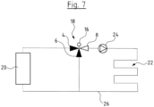
- the mixing valve as described above is used to adjust the temperature of a fluid flow, for example the feed temperature of a heating or cooling circuit.
- the first inlet port and the second inlet port are provided to deliver fluid flows of different temperature.
- the mixing ratio of these two fluid flows of different temperature can be changed to adjust the outlet temperature of the mixing valve.
- the outlet port of the valve is connected to the supply line of a heating or cooling circuit.
- the first inlet port for example may be connected to a heat source, for example a boiler.
- the first inlet port may be connected to a cooling device.
- the second inlet port preferably is connected to a return line from a heating or cooling circuit.
- the mixing point or mixing region in which the fluid flows from the first and second inlet port are admixed, is located inside the valve space and not inside one of the inlet ports. This allows an exact temperature measurement in both inlet ports without any influence from the other inlet port.
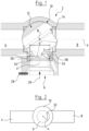
- the mixing valve there is arranged at least one temperature sensor 28 at least inside the second inlet port 6. Detecting the temperature inside the second inlet port 6 may be problematic in case that the fluid flow or pressure inside the first inlet port 4 is higher than in the second inlet port 8. Under these circumstances there may occur the problem that a fluid flow from the first inlet port enters into the second inlet port 6 against or upstream the usual flow direction 30 inside the second inlet port 6. This would influence the temperature detected by temperature sensor 28. To reduce or eliminate this problem, there is arranged an obstruction 32 inside the second inlet port 6. In the embodiments shown in Figs. 1 and 3 to 6 the obstruction 32 is ringshaped extending along the entire inner circumference of the second inlet port 6 about the longitudinal axis X in flow direction 30.
- the obstruction is not shown along the entire circumference, but on one side of the inner circumference of the second inlet port 6 only.
- the obstruction 32 in particular is arranged on a diameter side, with reference to the longitudinal direction X, of the second inlet port 6, which is away from the side on which the first inlet port 4 is located.
- the obstruction 32 is arranged on the side towards the outlet port 8.
- the obstruction 32 is arranged on an inner side of the second inlet port 6 which is facing the first inlet port 4.
- a fluid flow from the first inlet port 4 would primarily impinge on the side opposite, i. e. facing the first inlet port 4 which is the side with the obstruction 32.
- the obstruction 32 can influence a fluid flow entering from the first inlet port 4 into the second inlet port 6.
- the obstruction 32 extends according to the invention along the entire circumference as shown in the other figures.
- the obstruction 32 is integrally formed with the valve housing 2, i. e. with the portion of the valve housing 2 defining the second inlet port 6.
- the valve seat 40' is formed as an insert.
- the obstruction 32 is integrally formed with the portion of the valve housing 2 defining the second inlet port 6.
- the obstruction 32 is not lip-shaped but has a shape of a shoulder defining the pocket-like area 34.
- longitudinal direction i. e. in direction of the longitudinal axis X the obstruction 32 forms a reduction in diameter inside the second inlet port 6 extending in upstream direction. Further upstream the diameter is enlarged.
Landscapes
- Engineering & Computer Science (AREA)
- General Engineering & Computer Science (AREA)
- Mechanical Engineering (AREA)
- Physics & Mathematics (AREA)
- General Physics & Mathematics (AREA)
- Automation & Control Theory (AREA)
- Valve Housings (AREA)
- Multiple-Way Valves (AREA)
Claims (13)
- Mischventil, das eine erste Einlassöffnung (4), eine zweite Einlassöffnung (6), die sich quer zu der ersten Einlassöffnung (4) erstreckt, und eine Auslassöffnung (8) aufweist, wobei sich die Einlassöffnungen (4, 6) in eine Ventilkammer (10) hinaus öffnen und die Auslassöffnung (8) von dieser Ventilkammer (10) abzweigt, innerhalb derer ein bewegliches Ventilelement (12) angeordnet ist, und das ein Hindernis (32) innerhalb der zweiten Einlassöffnung (6) aufweist, das von einem inneren Umfang (36) der zweiten Einlassöffnung (6) aus in ihr Inneres vorspringt und das sich entlang des gesamten inneren Umfangs (36) erstreckt, wobei das Mischventil ferner einen Temperatursensor (28) aufweist, der an oder in der zweiten Einlassöffnung (6) stromaufwärts von dem Hindernis (32) angeordnet ist,
dadurch gekennzeichnet, dass
das Hindernis (32) und eine benachbarte umlaufende Wand (36) einen taschenartigen Bereich (34) auf der stromabwärts gelegenen Seite des Hindernisses (32) definieren, wobei der taschenartige Bereich (34) derart innerhalb der zweiten Einlassöffnung (6) angeordnet ist, dass ein Strom, der aus der ersten Einlassöffnung (4) in die zweite Einlassöffnung (6) eintritt, in dem Bereich dieses taschenartigen Bereichs (34) auf das Hindernis auftrifft und durch das Hindernis (32) in eine Richtung, zu der Ventilkammer (10) hin, umgelenkt wird oder innerhalb des taschenartigen Bereichs (34) eingeschlossen wird. - Mischventil nach Anspruch 1, dadurch gekennzeichnet, dass die erste Einlassöffnung (4) und die Auslassöffnung (8) auf entgegengesetzten Seiten der Ventilkammer (10) angeordnet sind, wobei die zweite Einlassöffnung (6) zwischen der Einlassöffnung (4) und der Auslassöffnung (8) angeordnet ist.
- Mischventil nach einem der vorhergehenden Ansprüche, dadurch gekennzeichnet, dass das Hindernis (32) eine erste Oberfläche auf seiner stromabwärts gelegenen Seite, gesehen in einer Strömungsrichtung (30) entlang der Längsachse (X) der zweiten Einlassöffnung (6), aufweist, wobei sich die erste Oberfläche abgewinkelt in Bezug auf die Längsachse (X) der zweiten Einlassöffnung (6) erstreckt.
- Mischventil nach Anspruch 3, dadurch gekennzeichnet, dass die erste Oberfläche in der Strömungsrichtung (30) in einem Winkel (A) zwischen 15° und 90° in Bezug auf die Längsachse (X) abgewinkelt ist.
- Mischventil nach einem der vorhergehenden Ansprüche, dadurch gekennzeichnet, dass die radiale Ausdehnung des Hindernisses (32) in Bezug auf die Längsachse (X) der zweiten Einlassöffnung (6) in dem Bereich von 3 % bis 25 % des inneren Durchmessers (D) der zweiten Einlassöffnung (6) liegt.
- Mischventil nach einem der vorhergehenden Ansprüche, dadurch gekennzeichnet, dass eine Entfernung (d) zwischen der äußeren Umfangsfläche des Ventilelements (12), wenn es die zweite Einlassöffnung (6) verschließt, und dem freien Ende des Hindernisses (32), das dem Ventilelement (12) am nächsten ist, in dem Bereich zwischen null und der Länge des inneren Durchmessers der zweiten Einlassöffnung (6) liegt.
- Mischventil nach einem der vorhergehenden Ansprüche, dadurch gekennzeichnet, dass das Hindernis (32) zumindest teilweise an einem Einsatz (38, 42) angeordnet ist, der in die zweite Einlassöffnung (6) eingesetzt ist.
- Mischventil nach einem der vorhergehenden Ansprüche, dadurch gekennzeichnet, dass zumindest ein Abschnitt des Hindernisses (32) integral mit einem Element (38) geformt ist, das einen Ventilsitz für das Ventilelement (12) umfasst.
- Mischventil nach einem der vorhergehenden Ansprüche, dadurch gekennzeichnet, dass zumindest ein Abschnitt des Hindernisses (32) integral mit einem Abschnitt eines Ventilgehäuses (2) geformt ist, der die Einlassöffnung (6) definiert.
- Mischventil nach einem der vorhergehenden Ansprüche, dadurch gekennzeichnet, dass der Querschnitt der zweiten Einlassöffnung (6) stromaufwärts von dem Hindernis (32) vergrößert ist.
- Mischventil nach einem der vorhergehenden Ansprüche, dadurch gekennzeichnet, dass das Ventilelement (12) kugelförmig ist.
- Heiz- oder Kühlanlage, gekennzeichnet durch ein Mischventil (18) nach einem der vorhergehenden Ansprüche, wobei die erste Einlassöffnung (4) und die zweite Einlassöffnung (6) bereitgestellt werden, um Fluidströme mit unterschiedlicher Temperatur bereitzustellen, und wobei in mindestens einem Betriebszustand der Strom durch die zweite Einlassöffnung (6) niedriger ist als der Strom durch die erste Einlassöffnung (4).
- Heiz- oder Kühlanlage nach Anspruch 12, dadurch gekennzeichnet, dass die erste Einlassöffnung (4) mit einer Wärmequelle (20) verbunden ist und die zweite Einlassöffnung (6) mit einer Rückführungsleitung (26) mindestens eines Heiz- oder Kühlkreislaufs der Heiz- oder Kühlanlage verbunden ist.
Priority Applications (3)
| Application Number | Priority Date | Filing Date | Title |
|---|---|---|---|
| EP20209825.7A EP4006685B1 (de) | 2020-11-25 | 2020-11-25 | Mischventil und heiz- oder kühlsystem |
| US17/535,487 US11859721B2 (en) | 2020-11-25 | 2021-11-24 | Mixing valve and heating or cooling system |
| CN202111411893.5A CN114542762B (zh) | 2020-11-25 | 2021-11-25 | 混合阀和加热或冷却系统 |
Applications Claiming Priority (1)
| Application Number | Priority Date | Filing Date | Title |
|---|---|---|---|
| EP20209825.7A EP4006685B1 (de) | 2020-11-25 | 2020-11-25 | Mischventil und heiz- oder kühlsystem |
Publications (3)
| Publication Number | Publication Date |
|---|---|
| EP4006685A1 EP4006685A1 (de) | 2022-06-01 |
| EP4006685B1 true EP4006685B1 (de) | 2024-07-10 |
| EP4006685C0 EP4006685C0 (de) | 2024-07-10 |
Family
ID=73597953
Family Applications (1)
| Application Number | Title | Priority Date | Filing Date |
|---|---|---|---|
| EP20209825.7A Active EP4006685B1 (de) | 2020-11-25 | 2020-11-25 | Mischventil und heiz- oder kühlsystem |
Country Status (3)
| Country | Link |
|---|---|
| US (1) | US11859721B2 (de) |
| EP (1) | EP4006685B1 (de) |
| CN (1) | CN114542762B (de) |
Families Citing this family (1)
| Publication number | Priority date | Publication date | Assignee | Title |
|---|---|---|---|---|
| WO2022109352A1 (en) * | 2020-11-19 | 2022-05-27 | Cft Llc | Valve and system |
Citations (1)
| Publication number | Priority date | Publication date | Assignee | Title |
|---|---|---|---|---|
| US20160178073A1 (en) * | 2014-12-22 | 2016-06-23 | Grundfos Holding A/S | Mixing valve |
Family Cites Families (9)
| Publication number | Priority date | Publication date | Assignee | Title |
|---|---|---|---|---|
| GB259996A (en) | 1925-10-16 | 1927-03-24 | Gen Electric | Improvements in or relating to dynamo electric machines |
| US7111643B2 (en) * | 2005-01-26 | 2006-09-26 | Invensys Building Systems, Inc. | Flow characterization in a flowpath |
| DE102010006861A1 (de) * | 2010-02-04 | 2011-08-04 | Jäger, Anton, 89250 | Reinigungsvorrichtung |
| EP2821679A1 (de) * | 2013-07-05 | 2015-01-07 | Esbe AB | Temperaturstellventil |
| JP6493300B2 (ja) | 2016-05-19 | 2019-04-03 | 株式会社デンソー | 流路切替弁 |
| US10465803B2 (en) * | 2016-10-05 | 2019-11-05 | Johnson Controls Technology Company | Multipurpose valve assembly tool |
| WO2018100872A1 (ja) * | 2016-11-29 | 2018-06-07 | 株式会社デンソー | 弁装置 |
| US11255449B2 (en) * | 2018-09-27 | 2022-02-22 | Aisin Corporation | Valve device |
| GB2599956B (en) * | 2020-10-19 | 2024-09-25 | Kohler Mira Ltd | Control system for one or more ablutionary devices |
-
2020
- 2020-11-25 EP EP20209825.7A patent/EP4006685B1/de active Active
-
2021
- 2021-11-24 US US17/535,487 patent/US11859721B2/en active Active
- 2021-11-25 CN CN202111411893.5A patent/CN114542762B/zh active Active
Patent Citations (1)
| Publication number | Priority date | Publication date | Assignee | Title |
|---|---|---|---|---|
| US20160178073A1 (en) * | 2014-12-22 | 2016-06-23 | Grundfos Holding A/S | Mixing valve |
Also Published As
| Publication number | Publication date |
|---|---|
| CN114542762B (zh) | 2024-02-13 |
| US11859721B2 (en) | 2024-01-02 |
| US20220163123A1 (en) | 2022-05-26 |
| CN114542762A (zh) | 2022-05-27 |
| EP4006685A1 (de) | 2022-06-01 |
| EP4006685C0 (de) | 2024-07-10 |
Similar Documents
| Publication | Publication Date | Title |
|---|---|---|
| KR102112278B1 (ko) | 차량의 열펌프 시스템용 밸브 | |
| US6935371B2 (en) | High capacity globe valve | |
| EP2400191A1 (de) | Vier-Wege-Ventil | |
| US9657652B2 (en) | Valve assembly and exhaust gas system | |
| EP3017219B1 (de) | Temperaturstellventil | |
| US20070063163A1 (en) | Butterfly valve assembly with improved flow characteristics | |
| EP4006685B1 (de) | Mischventil und heiz- oder kühlsystem | |
| EP3685081B1 (de) | Steuerventil mit leitschaufel | |
| US12449064B2 (en) | Cage valve | |
| US20220260180A1 (en) | Valve housing and globe valve for controlling a process fluid flow with a valve housing | |
| US20200350646A1 (en) | Battery system, in particular for driving a vehicle | |
| US6062249A (en) | Faucet side spray diverter | |
| US4941506A (en) | Sanitary mixing valve | |
| US12516743B2 (en) | Multi-port valve assembly | |
| JPH0535314B2 (de) | ||
| ZA200101984B (en) | Heating system, especially a heating and air-conditioning system with a mixing flap. | |
| JP5595359B2 (ja) | 流量制御弁 | |
| US5324008A (en) | Ball valve with offset through-duct | |
| US10746321B2 (en) | Valve having a bypass conduit | |
| US6681804B2 (en) | Device for controlling the output of rotary compressors | |
| JP7230403B2 (ja) | 湯水混合バルブ装置 | |
| US20200392882A1 (en) | Valve, exhaust branch for an internal combustion engine and vehicle having an internal combustion engine | |
| EP4330789A1 (de) | Wassermanagementsystem | |
| US20250319749A1 (en) | Vector air outlet and motor vehicle | |
| JP7794578B2 (ja) | 水栓 |
Legal Events
| Date | Code | Title | Description |
|---|---|---|---|
| PUAI | Public reference made under article 153(3) epc to a published international application that has entered the european phase |
Free format text: ORIGINAL CODE: 0009012 |
|
| STAA | Information on the status of an ep patent application or granted ep patent |
Free format text: STATUS: THE APPLICATION HAS BEEN PUBLISHED |
|
| AK | Designated contracting states |
Kind code of ref document: A1 Designated state(s): AL AT BE BG CH CY CZ DE DK EE ES FI FR GB GR HR HU IE IS IT LI LT LU LV MC MK MT NL NO PL PT RO RS SE SI SK SM TR |
|
| STAA | Information on the status of an ep patent application or granted ep patent |
Free format text: STATUS: REQUEST FOR EXAMINATION WAS MADE |
|
| 17P | Request for examination filed |
Effective date: 20221129 |
|
| RBV | Designated contracting states (corrected) |
Designated state(s): AL AT BE BG CH CY CZ DE DK EE ES FI FR GB GR HR HU IE IS IT LI LT LU LV MC MK MT NL NO PL PT RO RS SE SI SK SM TR |
|
| STAA | Information on the status of an ep patent application or granted ep patent |
Free format text: STATUS: EXAMINATION IS IN PROGRESS |
|
| 17Q | First examination report despatched |
Effective date: 20230414 |
|
| GRAP | Despatch of communication of intention to grant a patent |
Free format text: ORIGINAL CODE: EPIDOSNIGR1 |
|
| STAA | Information on the status of an ep patent application or granted ep patent |
Free format text: STATUS: GRANT OF PATENT IS INTENDED |
|
| INTG | Intention to grant announced |
Effective date: 20240131 |
|
| GRAJ | Information related to disapproval of communication of intention to grant by the applicant or resumption of examination proceedings by the epo deleted |
Free format text: ORIGINAL CODE: EPIDOSDIGR1 |
|
| STAA | Information on the status of an ep patent application or granted ep patent |
Free format text: STATUS: EXAMINATION IS IN PROGRESS |
|
| GRAP | Despatch of communication of intention to grant a patent |
Free format text: ORIGINAL CODE: EPIDOSNIGR1 |
|
| STAA | Information on the status of an ep patent application or granted ep patent |
Free format text: STATUS: GRANT OF PATENT IS INTENDED |
|
| GRAS | Grant fee paid |
Free format text: ORIGINAL CODE: EPIDOSNIGR3 |
|
| GRAA | (expected) grant |
Free format text: ORIGINAL CODE: 0009210 |
|
| STAA | Information on the status of an ep patent application or granted ep patent |
Free format text: STATUS: THE PATENT HAS BEEN GRANTED |
|
| INTC | Intention to grant announced (deleted) | ||
| INTG | Intention to grant announced |
Effective date: 20240531 |
|
| AK | Designated contracting states |
Kind code of ref document: B1 Designated state(s): AL AT BE BG CH CY CZ DE DK EE ES FI FR GB GR HR HU IE IS IT LI LT LU LV MC MK MT NL NO PL PT RO RS SE SI SK SM TR |
|
| REG | Reference to a national code |
Ref country code: CH Ref legal event code: EP |
|
| REG | Reference to a national code |
Ref country code: DE Ref legal event code: R096 Ref document number: 602020033671 Country of ref document: DE |
|
| U01 | Request for unitary effect filed |
Effective date: 20240710 |
|
| U07 | Unitary effect registered |
Designated state(s): AT BE BG DE DK EE FI FR IT LT LU LV MT NL PT RO SE SI Effective date: 20240902 |
|
| U1O | Appointed representative for the unitary patent procedure deleted after the registration of the unitary effect | ||
| U20 | Renewal fee for the european patent with unitary effect paid |
Year of fee payment: 5 Effective date: 20241126 |
|
| PG25 | Lapsed in a contracting state [announced via postgrant information from national office to epo] |
Ref country code: NO Free format text: LAPSE BECAUSE OF FAILURE TO SUBMIT A TRANSLATION OF THE DESCRIPTION OR TO PAY THE FEE WITHIN THE PRESCRIBED TIME-LIMIT Effective date: 20241010 |
|
| PG25 | Lapsed in a contracting state [announced via postgrant information from national office to epo] |
Ref country code: GR Free format text: LAPSE BECAUSE OF FAILURE TO SUBMIT A TRANSLATION OF THE DESCRIPTION OR TO PAY THE FEE WITHIN THE PRESCRIBED TIME-LIMIT Effective date: 20241011 Ref country code: PL Free format text: LAPSE BECAUSE OF FAILURE TO SUBMIT A TRANSLATION OF THE DESCRIPTION OR TO PAY THE FEE WITHIN THE PRESCRIBED TIME-LIMIT Effective date: 20240710 |
|
| PG25 | Lapsed in a contracting state [announced via postgrant information from national office to epo] |
Ref country code: IS Free format text: LAPSE BECAUSE OF FAILURE TO SUBMIT A TRANSLATION OF THE DESCRIPTION OR TO PAY THE FEE WITHIN THE PRESCRIBED TIME-LIMIT Effective date: 20241110 |
|
| PG25 | Lapsed in a contracting state [announced via postgrant information from national office to epo] |
Ref country code: HR Free format text: LAPSE BECAUSE OF FAILURE TO SUBMIT A TRANSLATION OF THE DESCRIPTION OR TO PAY THE FEE WITHIN THE PRESCRIBED TIME-LIMIT Effective date: 20240710 |
|
| PG25 | Lapsed in a contracting state [announced via postgrant information from national office to epo] |
Ref country code: RS Free format text: LAPSE BECAUSE OF FAILURE TO SUBMIT A TRANSLATION OF THE DESCRIPTION OR TO PAY THE FEE WITHIN THE PRESCRIBED TIME-LIMIT Effective date: 20241010 Ref country code: ES Free format text: LAPSE BECAUSE OF FAILURE TO SUBMIT A TRANSLATION OF THE DESCRIPTION OR TO PAY THE FEE WITHIN THE PRESCRIBED TIME-LIMIT Effective date: 20240710 |
|
| PG25 | Lapsed in a contracting state [announced via postgrant information from national office to epo] |
Ref country code: RS Free format text: LAPSE BECAUSE OF FAILURE TO SUBMIT A TRANSLATION OF THE DESCRIPTION OR TO PAY THE FEE WITHIN THE PRESCRIBED TIME-LIMIT Effective date: 20241010 Ref country code: PL Free format text: LAPSE BECAUSE OF FAILURE TO SUBMIT A TRANSLATION OF THE DESCRIPTION OR TO PAY THE FEE WITHIN THE PRESCRIBED TIME-LIMIT Effective date: 20240710 Ref country code: NO Free format text: LAPSE BECAUSE OF FAILURE TO SUBMIT A TRANSLATION OF THE DESCRIPTION OR TO PAY THE FEE WITHIN THE PRESCRIBED TIME-LIMIT Effective date: 20241010 Ref country code: IS Free format text: LAPSE BECAUSE OF FAILURE TO SUBMIT A TRANSLATION OF THE DESCRIPTION OR TO PAY THE FEE WITHIN THE PRESCRIBED TIME-LIMIT Effective date: 20241110 Ref country code: HR Free format text: LAPSE BECAUSE OF FAILURE TO SUBMIT A TRANSLATION OF THE DESCRIPTION OR TO PAY THE FEE WITHIN THE PRESCRIBED TIME-LIMIT Effective date: 20240710 Ref country code: GR Free format text: LAPSE BECAUSE OF FAILURE TO SUBMIT A TRANSLATION OF THE DESCRIPTION OR TO PAY THE FEE WITHIN THE PRESCRIBED TIME-LIMIT Effective date: 20241011 Ref country code: ES Free format text: LAPSE BECAUSE OF FAILURE TO SUBMIT A TRANSLATION OF THE DESCRIPTION OR TO PAY THE FEE WITHIN THE PRESCRIBED TIME-LIMIT Effective date: 20240710 |
|
| PG25 | Lapsed in a contracting state [announced via postgrant information from national office to epo] |
Ref country code: SM Free format text: LAPSE BECAUSE OF FAILURE TO SUBMIT A TRANSLATION OF THE DESCRIPTION OR TO PAY THE FEE WITHIN THE PRESCRIBED TIME-LIMIT Effective date: 20240710 |
|
| PG25 | Lapsed in a contracting state [announced via postgrant information from national office to epo] |
Ref country code: CZ Free format text: LAPSE BECAUSE OF FAILURE TO SUBMIT A TRANSLATION OF THE DESCRIPTION OR TO PAY THE FEE WITHIN THE PRESCRIBED TIME-LIMIT Effective date: 20240710 |
|
| PG25 | Lapsed in a contracting state [announced via postgrant information from national office to epo] |
Ref country code: SK Free format text: LAPSE BECAUSE OF FAILURE TO SUBMIT A TRANSLATION OF THE DESCRIPTION OR TO PAY THE FEE WITHIN THE PRESCRIBED TIME-LIMIT Effective date: 20240710 |
|
| PLBE | No opposition filed within time limit |
Free format text: ORIGINAL CODE: 0009261 |
|
| STAA | Information on the status of an ep patent application or granted ep patent |
Free format text: STATUS: NO OPPOSITION FILED WITHIN TIME LIMIT |
|
| 26N | No opposition filed |
Effective date: 20250411 |
|
| REG | Reference to a national code |
Ref country code: CH Ref legal event code: PL |
|
| PG25 | Lapsed in a contracting state [announced via postgrant information from national office to epo] |
Ref country code: MC Free format text: LAPSE BECAUSE OF FAILURE TO SUBMIT A TRANSLATION OF THE DESCRIPTION OR TO PAY THE FEE WITHIN THE PRESCRIBED TIME-LIMIT Effective date: 20240710 |
|
| REG | Reference to a national code |
Ref country code: CH Ref legal event code: PL |
|
| PG25 | Lapsed in a contracting state [announced via postgrant information from national office to epo] |
Ref country code: CH Free format text: LAPSE BECAUSE OF NON-PAYMENT OF DUE FEES Effective date: 20241130 |
|
| PG25 | Lapsed in a contracting state [announced via postgrant information from national office to epo] |
Ref country code: IE Free format text: LAPSE BECAUSE OF NON-PAYMENT OF DUE FEES Effective date: 20241125 |
|
| U20 | Renewal fee for the european patent with unitary effect paid |
Year of fee payment: 6 Effective date: 20251127 |
|
| PGFP | Annual fee paid to national office [announced via postgrant information from national office to epo] |
Ref country code: GB Payment date: 20251121 Year of fee payment: 6 |