EP4006602A1 - Fiber optic adapter assemblies including an adapter housing and a locking housing - Google Patents
Fiber optic adapter assemblies including an adapter housing and a locking housing Download PDFInfo
- Publication number
- EP4006602A1 EP4006602A1 EP21211142.1A EP21211142A EP4006602A1 EP 4006602 A1 EP4006602 A1 EP 4006602A1 EP 21211142 A EP21211142 A EP 21211142A EP 4006602 A1 EP4006602 A1 EP 4006602A1
- Authority
- EP
- European Patent Office
- Prior art keywords
- adapter
- housing
- locking
- fiber optic
- connector
- Prior art date
- Legal status (The legal status is an assumption and is not a legal conclusion. Google has not performed a legal analysis and makes no representation as to the accuracy of the status listed.)
- Granted
Links
Images






Classifications
-
- G—PHYSICS
- G02—OPTICS
- G02B—OPTICAL ELEMENTS, SYSTEMS OR APPARATUS
- G02B6/00—Light guides; Structural details of arrangements comprising light guides and other optical elements, e.g. couplings
- G02B6/24—Coupling light guides
- G02B6/36—Mechanical coupling means
- G02B6/38—Mechanical coupling means having fibre to fibre mating means
- G02B6/3807—Dismountable connectors, i.e. comprising plugs
- G02B6/381—Dismountable connectors, i.e. comprising plugs of the ferrule type, e.g. fibre ends embedded in ferrules, connecting a pair of fibres
- G02B6/3826—Dismountable connectors, i.e. comprising plugs of the ferrule type, e.g. fibre ends embedded in ferrules, connecting a pair of fibres characterised by form or shape
- G02B6/3831—Dismountable connectors, i.e. comprising plugs of the ferrule type, e.g. fibre ends embedded in ferrules, connecting a pair of fibres characterised by form or shape comprising a keying element on the plug or adapter, e.g. to forbid wrong connection
-
- G—PHYSICS
- G02—OPTICS
- G02B—OPTICAL ELEMENTS, SYSTEMS OR APPARATUS
- G02B6/00—Light guides; Structural details of arrangements comprising light guides and other optical elements, e.g. couplings
- G02B6/24—Coupling light guides
- G02B6/36—Mechanical coupling means
- G02B6/38—Mechanical coupling means having fibre to fibre mating means
- G02B6/3807—Dismountable connectors, i.e. comprising plugs
- G02B6/381—Dismountable connectors, i.e. comprising plugs of the ferrule type, e.g. fibre ends embedded in ferrules, connecting a pair of fibres
- G02B6/3825—Dismountable connectors, i.e. comprising plugs of the ferrule type, e.g. fibre ends embedded in ferrules, connecting a pair of fibres with an intermediate part, e.g. adapter, receptacle, linking two plugs
-
- G—PHYSICS
- G02—OPTICS
- G02B—OPTICAL ELEMENTS, SYSTEMS OR APPARATUS
- G02B6/00—Light guides; Structural details of arrangements comprising light guides and other optical elements, e.g. couplings
- G02B6/24—Coupling light guides
- G02B6/36—Mechanical coupling means
- G02B6/38—Mechanical coupling means having fibre to fibre mating means
- G02B6/3807—Dismountable connectors, i.e. comprising plugs
- G02B6/3833—Details of mounting fibres in ferrules; Assembly methods; Manufacture
- G02B6/3834—Means for centering or aligning the light guide within the ferrule
- G02B6/3843—Means for centering or aligning the light guide within the ferrule with auxiliary facilities for movably aligning or adjusting the fibre within its ferrule, e.g. measuring position or eccentricity
-
- G—PHYSICS
- G02—OPTICS
- G02B—OPTICAL ELEMENTS, SYSTEMS OR APPARATUS
- G02B6/00—Light guides; Structural details of arrangements comprising light guides and other optical elements, e.g. couplings
- G02B6/24—Coupling light guides
- G02B6/36—Mechanical coupling means
- G02B6/38—Mechanical coupling means having fibre to fibre mating means
- G02B6/3807—Dismountable connectors, i.e. comprising plugs
- G02B6/389—Dismountable connectors, i.e. comprising plugs characterised by the method of fastening connecting plugs and sockets, e.g. screw- or nut-lock, snap-in, bayonet type
-
- G—PHYSICS
- G02—OPTICS
- G02B—OPTICAL ELEMENTS, SYSTEMS OR APPARATUS
- G02B6/00—Light guides; Structural details of arrangements comprising light guides and other optical elements, e.g. couplings
- G02B6/24—Coupling light guides
- G02B6/36—Mechanical coupling means
- G02B6/38—Mechanical coupling means having fibre to fibre mating means
- G02B6/3807—Dismountable connectors, i.e. comprising plugs
- G02B6/3897—Connectors fixed to housings, casing, frames or circuit boards
Definitions
- the present disclosure generally relates to fiber optic adapter assemblies for connecting optical fibers, and more particularly to fiber optic adapter assemblies including an adapter housing and a locking housing.
- Optical fibers are used in an increasing number and variety of applications, such as a wide variety of telecommunications and data transmission applications.
- fiber optic networks include an ever increasing number of terminated optical fibers and fiber optic cables that can be conveniently and reliable mated with corresponding optical receptacles in the network.
- These terminated optical fibers and fiber optic cables are available in a variety of connectorized formats including, for example, hardened OptiTap ® and OptiTip ® connectors, field-installable UniCam ® connectors, preconnectorized single or multi-fiber cable assemblies with SC, FC, or LC connectors, etc., all of which are available from Corning Incorporated, with similar products available from other manufacturers, as is well documented in the patent literature.
- optical receptacles with which the aforementioned terminated fibers and cables are coupled are commonly provided at optical network units (ONUs), network interface devices (NIDs), and other types of network devices or enclosures, and often require hardware that is sufficiently robust to be employed in a variety of environments under a variety of installation conditions. These conditions may be attributable to the environment in which the connectors are employed, or the habits of the technicians handling the hardware. Consequently, there is a continuing drive to enhance the robustness of these connectorized assemblies, while preserving quick, reliable, and trouble-free optical connection to the network.
- Fiber optic connectors connectorized cable assemblies, closure assemblies, and methods for connecting fiber optic connectors to, and disconnecting fiber optic connectors from closure assemblies are disclosed herein.
- the present disclosure provides a fiber optic connector assembly comprising a connector housing defining a rotationally-discrete locking portion defined on an outer surface of the connector housing, an adapter assembly selectively coupled to the connector housing, the adapter assembly comprising an adapter housing extending around the connector housing and defining an adapter front end and an adapter retention member that is positionable between an engaged position, in which the adapter retention member restricts movement of the connector housing with respect to the adapter assembly in an axial direction, and a disengaged position, in which the connector housing is movable with respect to the adapter assembly in the axial direction, and a locking housing positioned between the adapter housing and the connector housing, the locking housing defining a locking front end positionable at least partially within the adapter housing, and a locking retention feature that is engaged with the adapter retention member when the adapter retention member is in the engaged position.
- the present disclosure provides the fiber optic connector assembly of aspect A1, wherein the locking retention feature comprises a slot defined on an outer surface of the locking housing.
- the present disclosure provides the fiber optic connector assembly of either of aspects A1 or A2, wherein the adapter retention member defines a forwardly-facing locking engagement face positioned at least partially within the locking retention feature of the locking housing in the engaged position.
- the present disclosure provides the fiber optic connector assembly of any of aspects A1-A3, wherein the adapter housing defines an outer surface and an inner surface, and wherein the adapter retention member comprises an arm extending inwardly from the inner surface.
- the present disclosure provides the fiber optic connector assembly of any of aspects A1-A4, wherein the adapter retention member defines a ramp facing rearwardly and outwardly in a radial direction.
- the present disclosure provides the fiber optic connector assembly of any of aspects A1-A5, further comprising a connector retention feature engaged with the locking housing, and wherein the rotationally-discrete locking portion of the connector housing defines a connector locking face engaged with the connector retention feature.
- the present disclosure provides the fiber optic connector assembly of aspect A6, wherein the connector retention feature comprises a clip engaged with an outer surface of the locking housing and the connector locking face.
- the present disclosure provides the fiber optic connector assembly of any of aspects A1-A7, further comprising a boot rearward of the connector housing in the axial direction, the boot defining a forwardly-extending adapter engagement feature.
- the present disclosure provides the fiber optic connector assembly of aspect A8, wherein the boot is movable between an engaged position, in which the forwardly-extending adapter engagement feature is engaged with the adapter retention member, and a disengaged position, in which the forwardly-extending adapter engagement feature is spaced apart from the adapter retention member.
- the present disclosure provides the fiber optic connector assembly of aspect A9, wherein the forwardly-extending adapter engagement feature of the boot restricts outward movement of the adapter retention member in a radial direction that is transverse to the axial direction in the engaged position.
- the present disclosure provides the fiber optic connector assembly any of aspects A8-A10, wherein the forwardly-extending adapter engagement feature is positioned between the inner surface of the adapter housing and the adapter retention member in the engaged position.
- the present disclosure provides the fiber optic connector assembly of any of aspects A8-A11, wherein the forwardly-extending adapter engagement feature comprises a finger extending forwardly from the boot.
- the present disclosure provides the fiber optic connector assembly of any of aspects A8-A12, further comprising a sealing element positioned between the connector housing and the locking housing.
- the present disclosure provides the fiber optic connector assembly of any of aspects A1-A12, further comprising a sealing element engaged with an outer surface of the adapter housing.
- the present disclosure provides the fiber optic connector assembly of any of aspects A1-A14, wherein the adapter housing comprises a plurality of adapter retention members positionable between the engaged position and the disengaged position.
- the present disclosure provides the fiber optic connector assembly of aspect A1, further comprising a boot rearward of the connector housing in the axial direction, the boot defining a forwardly-extending adapter engagement feature, and wherein the locking retention feature comprises a slot defined on an outer surface of the locking housing, the adapter retention member defines a forwardly-facing locking engagement face positioned at least partially within the locking retention feature of the locking housing in the engaged position, and the boot is movable between an engaged position, in which the forwardly-extending adapter engagement feature is engaged with the adapter retention member, and a disengaged position, in which the forwardly-extending adapter engagement feature is spaced apart from the adapter retention member.
- the present disclosure provides the fiber optic connector assembly of any of aspects A1-A16, wherein the locking housing defines a protrusion extending outward from an outer surface of the locking housing.
- the present disclosure provides a method for connecting a fiber optic connector assembly to a closure, the method comprising inserting a connector housing into a locking housing, the connector housing defining a locking portion defined on an outer surface of the connector housing, inserting the locking housing into an adapter housing, the adapter housing defining an adapter front end and an adapter retention member, and engaging the adapter retention member of the locking housing with a locking retention feature of the locking housing.
- the present disclosure provides the method of aspect A18, further comprising engaging the adapter retention member with a forwardly-extending adapter engagement feature of a boot positioned rearward of the connector housing.
- the present disclosure provides the method of aspect A19, wherein engaging the adapter retention member with the forwardly-extending adapter engagement feature of the boot comprises moving the forwardly-extending adapter engagement feature between an inner surface of the locking housing and the adapter retention member.
- the present disclosure provides a method for disconnecting a fiber optic connector assembly from a closure, the method comprising moving a boot rearward in an axial direction with respect to a locking housing engaged an adapter housing, thereby disengaging a forwardly-extending adapter engagement feature of the boot from an adapter retention member of the adapter housing, moving the locking housing rearward in the axial direction with respect to the adapter housing, thereby disengaging the adapter retention member from a locking retention feature of the locking housing, and moving the locking housing and a connector housing within the locking housing out of the adapter housing.
- the present disclosure provides the method of aspect A21, wherein disengaging the adapter retention member of the adapter housing from the locking retention feature of the locking housing comprises moving the adapter retention member outwardly in a radial direction.
- Embodiments described herein are directed to fiber optic connector assemblies including a connector housing and an adapter assembly including a locking housing and an adapter housing.
- the adapter housing may generally permit the connector housing to be engaged with a dissimilar coupling, for example of a closure.
- the connector housing may be selectively coupled to, and may be releasable from the adapter housing via the locking housing, thereby allowing the connector housing to be selectively coupled to and released from the dissimilar coupling and/or closure.
- the term “longitudinal direction” refers to the forward-rearward direction of the components described herein (i.e., in the +/- z-direction as depicted).
- the term “lateral direction” refers to the cross-wise direction of the components ( i . e ., in the +/- x-direction as depicted), and is transverse to the longitudinal direction.
- the term “vertical direction” refers to the upward-downward direction of the components (i.e., in the +/- y-direction as depicted).
- the term “axial direction” generally refers to the longitudinal direction of fiber optic connector assemblies described herein.
- radial direction refers to the direction extending outward from the longitudinal direction of fiber optic connector assemblies described herein ( i.e., in the R-direction as depicted).
- circumferential direction refers to the direction extending around the longitudinal direction of fiber optic connector assemblies described herein (i.e., in the C-direction as depicted).
- closure 200 is depicted with multiple fiber optic connector assemblies 100 inserted at least partially into the closure 200.
- the closure 200 may facilitate the connection of multiple fiber optic connector assemblies 100.
- the closure 200 may be a have de Protection d'epissurages optiques (BPEO) closure, however, it should be understood that this is merely an example.
- closures 200 may include multiple closure openings 202 that can each receive a fiber optic connector assembly 100.
- the closure openings 202 may be positioned adjacent to one another in the vertical direction and/or in the lateral direction (i.e., in the +/- y-direction and the +/-x-direction as depicted).
- the closure openings 202 may be positioned on top of one another in the vertical direction, and may be placed side-by-side to one another in the lateral direction (i.e., in the +/- y-direction and the +/-x-direction as depicted, respectively).
- the closure openings 202 may be positioned adjacent to one another in the vertical direction and the lateral direction (i.e., in the +/- y-direction and the +/-x-direction as depicted), multiple fiber optic connector assemblies 100 may be inserted into the closure 200 even when the closure 200 has a comparatively small footprint evaluated in the vertical and lateral directions.
- the number of fiber optic connector assemblies 100 inserted into the closure 200 may be increased as compared to similarly-sized closures having closure openings 202 that are not positioned adjacent to one another in the vertical direction and the lateral direction.
- fiber optic connector assemblies 100 positioned adjacent to one another in the vertical direction and the lateral direction (i.e., in the +/- y-direction and the +/x-direction as depicted), it may be difficult for users to insert and remove the fiber optic connector assemblies 100 from the closure 200.
- space between adjacent fiber optic connector assemblies 100 in the vertical direction and the lateral direction i.e., in the +/y-direction and the +/-x-direction as depicted, respectively
- Minimal distance between the fiber optic connector assemblies 100 may make it difficult for a user to manipulate any of the fiber optic connector assemblies 100 to remove or insert the fiber optic connector assemblies 100 to the closure 200.
- the fiber optic connector assembly 100 includes a connector housing 110 and an adapter assembly 130 including a locking housing 140.
- the locking housing 140 is engageable with the connector housing 110.
- the connector housing may be insertable at least partially within the locking housing 140, as shown in FIG. 3 .
- the connector housing 110 defines an outer surface 116 extending from a rear end 122 to a front end 120 in the longitudinal direction (i.e., in the +/- z-direction as depicted).
- a ferrule 108 may be positioned at the front end 120 of the connector housing 110.
- An optical fiber may extend through the ferrule 108 in the longitudinal direction (i. e., in the +/- z-direction as depicted).
- the optical fiber may be coaxial with the longitudinal direction (i.e., the +/- z-direction as depicted). For multifiber cables, this alignment will be offset for one, more than one, or all of the optical fibers of the fiber optic cable 10.
- the locking housing 140 defines an outer surface 148 extending from a locking rear end 146 to a locking front end 144 in the longitudinal direction (i.e., in the +/- z-direction as depicted).
- locking housing 140 defines one or more locking retention features 142 on the outer surface 148.
- the one or more locking retention features 142 may be slots extending inwardly into the outer surface 148 of the locking housing 140.
- the connector housing 110 When assembled, the connector housing 110 may be at least partially inserted into the locking housing 140.
- the connector housing 110 defines a connector keying portion 114 that interfaces with a complementary locking housing keying portion such that the connector housing 110 may be inserted into the locking housing 140 only in one rotational orientation. While in the embodiment depicted in FIG. 2 , the connector keying portion 114 of the connector housing 110 is depicted as a negative cutout, it should be understood that this is merely an example.
- the connector keying portion 114 of the connector housing 110 and the complementary locking housing keying portion may include any suitable complementary shapes to restrict rotation between the locking housing 140 and the connector housing 110 and to ensure rotational alignment between the locking housing 140 and the connector housing 110.
- the connector keying portion 114 may be a positive surface projection extending outward from the outer surface 116 of the connector housing 110.
- FIG. 4 a perspective view of the connector housing 110, the locking housing 140, and an adapter housing 160 is schematically depicted.
- the locking housing 140 (and accordingly the connector housing 110) may be inserted at least partially within the adapter housing 160, as described in greater detail herein.
- the adapter housing 160 generally extends between an adapter front end 164 to an adapter front end 162 in the longitudinal direction (i.e., in the +/- z-direction depicted in FIG. 4 ).
- the adapter front end 162 is engageable with a coupling 20.
- the coupling 20 is embodied as an SC coupling, however, it should be understood that this is merely an example, and the adapter housing 160 may be engageable with any suitable coupling, for example and without limitation, an LC coupling or the like.
- couplings 20 may be positioned at least partially within the closure openings 202 ( FIG. 1 ), and the fiber optic connector assemblies 100 inserted into the closure 200 ( FIG. 1 ) may each interface with a coupling 20.
- the locking housing 140 defines an outer locking keying feature 154 extending outwardly from the outer surface 148 of the locking housing 140.
- the outer locking keying feature 154 interfaces with a complementary adapter housing keying feature of the adapter housing 160, such that the locking housing 140 may be inserted into the adapter housing 160 only in one rotational orientation. While in the embodiment depicted in FIG. 4 , the outer locking keying feature 154 of the locking housing 140 is depicted as a positive surface projection, it should be understood that this is merely an example.
- the outer locking keying feature 154 of the locking housing 140 and the complementary adapter housing keying feature of the adapter housing 160 may include any suitable complementary shapes to restrict rotation between the locking housing 140 and the adapter housing 160 and to ensure rotational alignment between the locking housing 140 and the adapter housing 160.
- the outer locking keying feature 154 may be a negative cutout extending inwardly from the outer surface 148 of the locking housing 140.
- the fiber optic connector assembly 100 further includes a boot 180 rearward of the connector housing 110 ( FIG. 2 ) in the axial direction (i.e., in the -z-direction as depicted).
- the boot 180 may be selectively movable with respect to the adapter housing 160 in the axial direction ( i.e., in the +/- z-direction as depicted), as described in greater detail herein.
- the fiber optic connector assembly 100 may include one or more sealing elements 136 engaged with the connector housing 110, the locking housing 140, and/or the adapter housing 160.
- the one or more sealing elements 136 may include o-rings or the like.
- a sealing element 136 may be positioned on the connector housing 110 and may be positioned between the connector housing 110 and the locking housing 140 ( FIG. 7 ).
- the fiber optic connector assembly 100 may include a rear seal 132 positioned at least partially around the connector housing 110.
- the rear seal 132 may be restrict environmental elements (e . g ., water, humidity, etc.) from passing between the connector housing 110 and locking housing 140, and may include any suitable material for restricting the passage of environmental elements, for example and without limitation, a polymer or the like.
- a sealing element 136 may be positioned on the locking housing 140 and may be positioned between the adapter housing 160 ( FIG. 8 ) and the locking housing 140.
- a sealing element 136 may be positioned on the adapter housing 160.
- the sealing elements 136 may assist in restricting the passage of environmental elements (e . g ., water, humidity, etc.) to interior portions of the fiber optic connector assembly 100, as described in greater detail herein.
- the fiber optic connector assembly 100 includes a connector retention feature 150 engaged with the locking housing 140.
- the connector retention feature 150 may include a clip or the like that restricts movement of the connector housing 110 with respect to the locking housing 140 in the axial direction (i.e., in the -z-direction as depicted).
- the connector housing 110 defines a rotationally-discrete locking portion 112 on the outer surface 116 of the connector housing 110.
- rotationally discrete represents a limited width-wise extent along the outer surface 116 of the connector housing 110, as the connector housing 110 is rotated in the circumferential direction C.
- the rotationally-discrete locking portion 112 defines a connector locking face 113 that, in the embodiment depicted in FIG. 11 faces rearwardly in the longitudinal direction ( i . e ., in the -z-direction as depicted).
- the connector retention feature 150 in embodiments, is engaged with the connector locking face 113 and restricts movement of the connector housing 110 with respect to locking housing 140 in the axial direction ( e . g ., in the -z-direction as depicted).
- the outer surface 148 of the locking housing 140 defines a groove 149.
- the connector retention feature 150 may be seated at least partially within the groove 149 such that movement of the connector retention feature 150 in the axial direction ( i . e ., in the +/- z-direction as depicted) with respect to the locking housing 140 is restricted.
- the connector retention feature 150 may restrict withdrawal of the connector housing 110 from the adapter housing 160 in the -z-direction as depicted.
- the boot 180 is depicted in isolation.
- the boot 180 defines one or more forwardly-extending adapter engagement features 182.
- the forwardly-extending adapter engagement features 182 may be embodied as fingers extending forward from the boot 180.
- the forwardly-extending adapter engagement features 182 may be rotationally-discrete about the boot 180, however, it should be understood that this is merely an example.
- the boot 180 further defines a rotationally-discrete orientation indicator 184.
- the rotationally-discrete orientation indicator 184 may assist a user, such as a technician in rotationally aligning the forwardly-extending adapter engagement features 182 with the adapter housing 160 ( FIG. 8 ), as described in greater detail herein.
- the boot 180 may have a varying thickness along the axial direction ( i . e ., in the +/- z-direction), which may allow the boot 180 to bend as desired in the radial direction and/or to assist a user in gripping the boot 180.
- the locking housing 140 and the adapter housing 160 are schematically depicted.
- the locking housing 140 defines the one or more locking retention features 142.
- the adapter housing 160 in embodiments, the adapter housing 160 defines one or more adapter retention members 170 that are engageable with the one or more locking retention features 142 of the locking housing 140 as the locking housing 140 is inserted into the adapter housing 160.
- the one or more adapter retention members 170 in some embodiments, may include arms extend inwardly from an adapter inner surface 166 of the adapter housing 160. In the embodiment depicted in FIGS.
- the locking housing 140 defines four locking retention features 142
- the adapter housing 160 defines four adapter retention members 170
- the locking housing 140 may include any suitable number of locking retention features 142
- the adapter housing 160 may include any suitable number of corresponding adapter retention members 170.
- the adapter retention members 170 may restrict movement of the locking housing 140 with respect to the adapter housing 160 when engaged with the locking retention features 142 of the locking housing 140.
- FIGS. 17-20 section views of the fiber optic connector assembly 100 are schematically depicted.
- the connector housing 110 is inserted at least partially into the locking housing 140.
- the adapter housing 160 may be engaged with the coupling 20.
- the one or more adapter retention members 170 may engage the one or more locking retention features 142 of the locking housing 140.
- the one or more adapter retention members 170 are positionable in a disengaged position as shown in FIGS 17 and 18 , in which the locking housing 140 (and accordingly the connector housing 110) are movable with respect to the adapter housing 160 in the axial direction ( i . e ., in the +/- z-direction as depicted).
- the one or more adapter retention members 170 are also positionable in an engaged position, as shown in FIG.
- the one or more adapter retention members 170 restrict movement of the locking housing 140 (and accordingly the connector housing 110) in the axial direction (i.e., in the +/- z-direction as depicted), for example, through engagement with the one or more locking retention features 142 of the locking housing 140.
- the boot 180 is movable between a disengaged position, as shown in FIG. 19 , and an engaged position, as shown in FIG. 20 .
- the forwardly-extending adapter engagement features 182 are spaced apart from the one or more adapter retention members 170 ( e.g., in the z-direction as depicted).
- the forwardly-extending adapter engagement features 182 of the boot 180 are engaged with the one or more adapter retention members 170.
- the one or more adapter retention members 170 may define a forwardly-facing locking engagement face 172 and/or a rearwardly-facing locking engagement face 173 that are positioned at least partially within the locking retention feature 142 of the locking housing 140. Engagement between the forwardly-facing locking engagement face 172 and the rearwardly-facing locking engagement face 173 with the locking retention feature 142 may restrict movement of the locking housing 140 with respect to the adapter housing 160 in the axial direction (i.e., in the +/- z-direction as depicted).
- the one or more adapter retention members 170 may define a ramp 174 facing rearwardly and outwardly in the radial direction.
- the ramp 174 may assist in moving the forwardly-extending adapter engagement feature 182 of the boot 180 between the one or more adapter retention members 170 and the adapter inner surface 166.
- the forwardly-extending adapter engagement features 182 of the boot 180 are positioned between the one or more adapter retention members 170 and the adapter inner surface 166 of the adapter housing 160.
- the forwardly-extending adapter engagement features 182 of the boot 180 With the forwardly-extending adapter engagement features 182 of the boot 180 positioned between the one or more adapter retention members 170 and the adapter inner surface 166, the forwardly-extending adapter engagement features 182 of the boot 180 restrict outward movement of the one or more adapter retention members 170 in the radial direction R. By restricting outward movement of the one or more adapter retention members 170, the forwardly-extending adapter engagement features 182 of the boot 180 may generally restrict disengagement of the one or more adapter retention members 170 from the locking retention features 142 of the locking housing 140.
- the forwardly-extending adapter engagement features 182 may assist in retaining a position of the locking housing 140 (and accordingly the connector housing 110 ( FIG. 20 ) with respect to the adapter housing 160.
- the boot 180 can be re-positioned in the disengaged position.
- the one or more adapter retention members 170 can be disengaged from the locking retention features 142 of the locking housing 140.
- the one or more adapter retention members 170 can be disengaged from the locking retention features 142 by move the locking housing 140 rearward in the axial direction ( i . e ., in the -z-direction as depicted) with a force above a predetermined threshold. In this way, the locking housing 140 (and accordingly the connector housing 110 ( FIG. 20 )) can be selectively connected to and disconnected from the adapter housing 160.
- the boot 180 may be formed from a resilient material, such as a polymer or the like.
- the forwardly-extending adapter engagement features 182 of the boot 180 may allow some movement of the one or more adapter retention members 170 outward in the radial direction R, for example, upon the application of a force exceeding a predetermined threshold.
- the forwardly-extending adapter engagement features 182 of the boot 180 may allow the one or more adapter retention members 170 to move outward in the radial direction R upon the application of a force to the locking housing 140 rearward in the axial direction ( i . e ., in the -z-direction as depicted) above a predetermined threshold.
- the predetermined threshold is about 25 decanewtons.
- the boot 180 defines an inwardly-extending boot inner ridge 186 that is selectively engageable with the locking housing 140.
- the locking housing 140 defines a locking protrusion 152 extending outwardly from the outer surface 148 of the locking housing 140.
- the boot inner ridge 186 may engage the locking protrusion 152 as the boot 180 moves forward in the axial direction (i.e., in the +z-direction as depicted) and engagement between the boot inner ridge 186 and the locking protrusion 152 may provide tactile feedback to a user moving the boot 180 forward in the axial direction.
- the boot inner ridge 186 and the locking protrusion 152 may be positioned such that the boot inner ridge 186 engages the locking protrusion 152 as the boot 180 moves into the engaged position, thereby providing tactile feedback to the user that the boot 180 is in the engaged position.
- inventions described herein are directed to fiber optic connector assemblies including a connector housing and an adapter assembly including a locking housing and an adapter housing.
- the adapter housing may generally permit the connector housing to be engaged with a dissimilar coupling, for example of a closure.
- the connector housing may be selectively coupled to, and may be releasable from the adapter housing via the locking housing, thereby allowing the connector housing to be selectively coupled to and released from the dissimilar coupling and/or closure.
- references herein of a component of the present disclosure being "structurally configured" in a particular way, to embody a particular property, or to function in a particular manner, are structural recitations, as opposed to recitations of intended use. More specifically, the references herein to the manner in which a component is “structurally configured” denotes an existing physical condition of the component and, as such, is to be taken as a definite recitation of the structural characteristics of the component.
Landscapes
- Physics & Mathematics (AREA)
- General Physics & Mathematics (AREA)
- Optics & Photonics (AREA)
- Mechanical Coupling Of Light Guides (AREA)
Abstract
Description
- This application claims the benefit of priority of
U.S. Provisional Application Serial No. 63/119,596, filed November 30, 2020 - The present disclosure generally relates to fiber optic adapter assemblies for connecting optical fibers, and more particularly to fiber optic adapter assemblies including an adapter housing and a locking housing.
- Optical fibers are used in an increasing number and variety of applications, such as a wide variety of telecommunications and data transmission applications. As a result, fiber optic networks include an ever increasing number of terminated optical fibers and fiber optic cables that can be conveniently and reliable mated with corresponding optical receptacles in the network. These terminated optical fibers and fiber optic cables are available in a variety of connectorized formats including, for example, hardened OptiTap® and OptiTip® connectors, field-installable UniCam® connectors, preconnectorized single or multi-fiber cable assemblies with SC, FC, or LC connectors, etc., all of which are available from Corning Incorporated, with similar products available from other manufacturers, as is well documented in the patent literature.
- The optical receptacles with which the aforementioned terminated fibers and cables are coupled are commonly provided at optical network units (ONUs), network interface devices (NIDs), and other types of network devices or enclosures, and often require hardware that is sufficiently robust to be employed in a variety of environments under a variety of installation conditions. These conditions may be attributable to the environment in which the connectors are employed, or the habits of the technicians handling the hardware. Consequently, there is a continuing drive to enhance the robustness of these connectorized assemblies, while preserving quick, reliable, and trouble-free optical connection to the network.
- Fiber optic connectors, connectorized cable assemblies, closure assemblies, and methods for connecting fiber optic connectors to, and disconnecting fiber optic connectors from closure assemblies are disclosed herein.
- In a first aspect A1, the present disclosure provides a fiber optic connector assembly comprising a connector housing defining a rotationally-discrete locking portion defined on an outer surface of the connector housing, an adapter assembly selectively coupled to the connector housing, the adapter assembly comprising an adapter housing extending around the connector housing and defining an adapter front end and an adapter retention member that is positionable between an engaged position, in which the adapter retention member restricts movement of the connector housing with respect to the adapter assembly in an axial direction, and a disengaged position, in which the connector housing is movable with respect to the adapter assembly in the axial direction, and a locking housing positioned between the adapter housing and the connector housing, the locking housing defining a locking front end positionable at least partially within the adapter housing, and a locking retention feature that is engaged with the adapter retention member when the adapter retention member is in the engaged position.
- In a second aspect A2, the present disclosure provides the fiber optic connector assembly of aspect A1, wherein the locking retention feature comprises a slot defined on an outer surface of the locking housing.
- In a third aspect A3, the present disclosure provides the fiber optic connector assembly of either of aspects A1 or A2, wherein the adapter retention member defines a forwardly-facing locking engagement face positioned at least partially within the locking retention feature of the locking housing in the engaged position.
- In a fourth aspect A4, the present disclosure provides the fiber optic connector assembly of any of aspects A1-A3, wherein the adapter housing defines an outer surface and an inner surface, and wherein the adapter retention member comprises an arm extending inwardly from the inner surface.
- In a fifth aspect A5, the present disclosure provides the fiber optic connector assembly of any of aspects A1-A4, wherein the adapter retention member defines a ramp facing rearwardly and outwardly in a radial direction.
- In a sixth aspect A6, the present disclosure provides the fiber optic connector assembly of any of aspects A1-A5, further comprising a connector retention feature engaged with the locking housing, and wherein the rotationally-discrete locking portion of the connector housing defines a connector locking face engaged with the connector retention feature.
- In a seventh aspect A7, the present disclosure provides the fiber optic connector assembly of aspect A6, wherein the connector retention feature comprises a clip engaged with an outer surface of the locking housing and the connector locking face.
- In an eighth A8, the present disclosure provides the fiber optic connector assembly of any of aspects A1-A7, further comprising a boot rearward of the connector housing in the axial direction, the boot defining a forwardly-extending adapter engagement feature.
- In a ninth aspect A9, the present disclosure provides the fiber optic connector assembly of aspect A8, wherein the boot is movable between an engaged position, in which the forwardly-extending adapter engagement feature is engaged with the adapter retention member, and a disengaged position, in which the forwardly-extending adapter engagement feature is spaced apart from the adapter retention member.
- In a tenth aspect A10, the present disclosure provides the fiber optic connector assembly of aspect A9, wherein the forwardly-extending adapter engagement feature of the boot restricts outward movement of the adapter retention member in a radial direction that is transverse to the axial direction in the engaged position.
- In an eleventh aspect A11, the present disclosure provides the fiber optic connector assembly any of aspects A8-A10, wherein the forwardly-extending adapter engagement feature is positioned between the inner surface of the adapter housing and the adapter retention member in the engaged position.
- In a twelfth aspect A12, the present disclosure provides the fiber optic connector assembly of any of aspects A8-A11, wherein the forwardly-extending adapter engagement feature comprises a finger extending forwardly from the boot.
- In a thirteenth aspect A13, the present disclosure provides the fiber optic connector assembly of any of aspects A8-A12, further comprising a sealing element positioned between the connector housing and the locking housing.
- In a fourteenth aspect A14, the present disclosure provides the fiber optic connector assembly of any of aspects A1-A12, further comprising a sealing element engaged with an outer surface of the adapter housing.
- In a fifteenth aspect A15, the present disclosure provides the fiber optic connector assembly of any of aspects A1-A14, wherein the adapter housing comprises a plurality of adapter retention members positionable between the engaged position and the disengaged position.
- In a sixteenth aspect A16, the present disclosure provides the fiber optic connector assembly of aspect A1, further comprising a boot rearward of the connector housing in the axial direction, the boot defining a forwardly-extending adapter engagement feature, and wherein the locking retention feature comprises a slot defined on an outer surface of the locking housing, the adapter retention member defines a forwardly-facing locking engagement face positioned at least partially within the locking retention feature of the locking housing in the engaged position, and the boot is movable between an engaged position, in which the forwardly-extending adapter engagement feature is engaged with the adapter retention member, and a disengaged position, in which the forwardly-extending adapter engagement feature is spaced apart from the adapter retention member.
- In a seventeenth aspect A17, the present disclosure provides the fiber optic connector assembly of any of aspects A1-A16, wherein the locking housing defines a protrusion extending outward from an outer surface of the locking housing.
- In an eighteenth aspect A18, the present disclosure provides a method for connecting a fiber optic connector assembly to a closure, the method comprising inserting a connector housing into a locking housing, the connector housing defining a locking portion defined on an outer surface of the connector housing, inserting the locking housing into an adapter housing, the adapter housing defining an adapter front end and an adapter retention member, and engaging the adapter retention member of the locking housing with a locking retention feature of the locking housing.
- In a nineteenth aspect A19, the present disclosure provides the method of aspect A18, further comprising engaging the adapter retention member with a forwardly-extending adapter engagement feature of a boot positioned rearward of the connector housing.
- In a twentieth aspect A20, the present disclosure provides the method of aspect A19, wherein engaging the adapter retention member with the forwardly-extending adapter engagement feature of the boot comprises moving the forwardly-extending adapter engagement feature between an inner surface of the locking housing and the adapter retention member.
- In a twenty-first aspect A21, the present disclosure provides a method for disconnecting a fiber optic connector assembly from a closure, the method comprising moving a boot rearward in an axial direction with respect to a locking housing engaged an adapter housing, thereby disengaging a forwardly-extending adapter engagement feature of the boot from an adapter retention member of the adapter housing, moving the locking housing rearward in the axial direction with respect to the adapter housing, thereby disengaging the adapter retention member from a locking retention feature of the locking housing, and moving the locking housing and a connector housing within the locking housing out of the adapter housing.
- In a twenty-second aspect A22, the present disclosure provides the method of aspect A21, wherein disengaging the adapter retention member of the adapter housing from the locking retention feature of the locking housing comprises moving the adapter retention member outwardly in a radial direction.
- Additional features of fiber optic connectors, connectorized cable assemblies, closure assemblies, and methods for connecting fiber optic connectors to, and disconnecting fiber optic connectors from closure assemblies will be set forth in the detailed description which follows, and in part will be readily apparent to those skilled in the art from that description or recognized by practicing the embodiments described herein, including the detailed description which follows, the claims, as well as the appended drawings.
- It is to be understood that both the foregoing general description and the following detailed description describe various embodiments and are intended to provide an overview or framework for understanding the nature and character of the claimed subject matter. The accompanying drawings are included to provide a further understanding of the various embodiments, and are incorporated into and constitute a part of this specification. The drawings illustrate the various embodiments described herein, and together with the description serve to explain the principles and operations of the claimed subject matter.
-
-
FIG. 1 schematically depicts a perspective view of a closure and fiber optic connector assemblies inserted at least partially into the closure, according to one or more embodiments shown and described herein; -
FIG. 2 schematically depicts a perspective view of a fiber optic connector assembly including a connector housing and a locking housing, according to one or more embodiments shown and described herein; -
FIG. 3 schematically depicts a perspective view of the connector housing inserted at least partially within the locking housing ofFIG. 2 , according to one or more embodiments shown and described herein; -
FIG. 4 schematically depicts a perspective view of the connector housing and the locking housing ofFIG. 2 , and a boot, an adapter housing, and a coupling, according to one or more embodiments shown and described herein; -
FIG. 5 schematically depicts a perspective view of the connector housing and the locking housing ofFIG. 2 inserted at least partially into the adapter housing ofFIG. 4 , according to one or more embodiments shown and described herein; -
FIG. 6 schematically depicts a perspective view of the connector housing ofFIG. 2 including a sealing element and a rear seal, according to one or more embodiments shown and described herein; -
FIG. 7 schematically depicts a perspective view of the locking housing and the boot ofFIG. 4 and a sealing element, according to one or more embodiments shown and described herein; -
FIG. 8 schematically depicts a perspective view of the adapter housing and the coupling ofFIG. 4 and a sealing element, according to one or more embodiments shown and described herein; -
FIG. 9 schematically depicts a perspective view of the connector housing and the locking housing ofFIG. 2 and a connector retention feature, according to one or more embodiments shown and described herein; -
FIG. 10 schematically depicts a perspective view of the connector retention feature ofFIG. 9 in isolation, according to one or more embodiments shown and described herein; -
FIG. 11 schematically depicts a perspective view of the connector housing ofFIG. 2 engaged with the connector retention feature ofFIG. 9 , according to one or more embodiments shown and described herein; -
FIG. 12 schematically depicts a perspective view of the boot ofFIG. 4 , according to one or more embodiments shown and described herein; -
FIG. 13 schematically depicts an enlarged perspective view of the boot ofFIG. 12 , according to one or more embodiments shown and described herein; -
FIG. 14 schematically depicts a side view of the locking housing ofFIG. 7 , according to one or more embodiments shown and described herein; -
FIG. 15 schematically depicts a section view of the adapter housing ofFIG. 8 , according to one or more embodiments shown and described herein; -
FIG. 16 schematically depicts a rear perspective view of the adapter housing ofFIG. 15 , according to one or more embodiments shown and described herein; -
FIG. 17 schematically depicts a section view of the connector housing and the locking housing approaching the adapter housing ofFIG. 4 , according to one or more embodiments shown and described herein; -
FIG. 18 schematically depicts a section view of the connector housing and the locking housing ofFIG. 17 inserted at least partially within the adapter housing, according to one or more embodiments shown and described herein; -
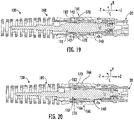
FIG. 19 schematically depicts a section view of the connector housing and the locking housingFIG. 17 inserted into the adapter housing, according to one or more embodiments shown and described herein; -
FIG. 20 schematically depicts a section view of the connector housing, the locking housing, and the adapter housing ofFIG. 19 with the boot positioned in an engaged position, according to one or more embodiments shown and described herein; -
FIG. 21 schematically depicts an enlarged section view of the connector housing, the locking housing, and the adapter housing ofFIG. 19 with the boot positioned in the disengaged position, according to one or more embodiments shown and described herein; -
FIG. 22 schematically depicts an enlarged section view of the connector housing, the locking housing, and the adapter housing ofFIG. 19 with the boot positioned in the engaged position, according to one or more embodiments shown and described herein; -
FIG. 23 schematically depicts a section view of the connector housing, the locking housing, the adapter housing, and the boot ofFIG. 5 , according to one or more embodiments shown and described herein; -
FIG. 24 schematically depicts an enlarged section view of the connector housing, the locking housing, and the boot ofFIG. 23 , according to one or more embodiments shown and described herein. - Reference will now be made in detail to embodiments of optical adapter assemblies, examples of which are illustrated in the accompanying drawings. Whenever possible, the same reference numerals will be used throughout the drawings to refer to the same or like parts. Embodiments described herein are directed to fiber optic connector assemblies including a connector housing and an adapter assembly including a locking housing and an adapter housing. The adapter housing may generally permit the connector housing to be engaged with a dissimilar coupling, for example of a closure. The connector housing may be selectively coupled to, and may be releasable from the adapter housing via the locking housing, thereby allowing the connector housing to be selectively coupled to and released from the dissimilar coupling and/or closure.
- As used herein, the term "longitudinal direction" refers to the forward-rearward direction of the components described herein (i.e., in the +/- z-direction as depicted). The term "lateral direction" refers to the cross-wise direction of the components (i.e., in the +/- x-direction as depicted), and is transverse to the longitudinal direction. The term "vertical direction" refers to the upward-downward direction of the components (i.e., in the +/- y-direction as depicted). The term "axial direction" generally refers to the longitudinal direction of fiber optic connector assemblies described herein. The term "radial direction" refers to the direction extending outward from the longitudinal direction of fiber optic connector assemblies described herein (i.e., in the R-direction as depicted). The term "circumferential direction refers to the direction extending around the longitudinal direction of fiber optic connector assemblies described herein (i.e., in the C-direction as depicted).
- Referring initially to
FIG. 1 , aclosure 200 is depicted with multiple fiberoptic connector assemblies 100 inserted at least partially into theclosure 200. In embodiments, theclosure 200 may facilitate the connection of multiple fiberoptic connector assemblies 100. In some embodiments, theclosure 200 may be a boite de Protection d'epissurages optiques (BPEO) closure, however, it should be understood that this is merely an example. As shown inFIG. 1 ,closures 200 may includemultiple closure openings 202 that can each receive a fiberoptic connector assembly 100. In embodiments, theclosure openings 202 may be positioned adjacent to one another in the vertical direction and/or in the lateral direction (i.e., in the +/- y-direction and the +/-x-direction as depicted). In other words, theclosure openings 202 may be positioned on top of one another in the vertical direction, and may be placed side-by-side to one another in the lateral direction (i.e., in the +/- y-direction and the +/-x-direction as depicted, respectively). By positioning theclosure openings 202 adjacent to one another in the vertical direction and the lateral direction (i.e., in the +/- y-direction and the +/-x-direction as depicted), multiple fiberoptic connector assemblies 100 may be inserted into theclosure 200 even when theclosure 200 has a comparatively small footprint evaluated in the vertical and lateral directions. In other words, by positioning theclosure openings 202 adjacent to one another in the vertical direction and the lateral direction, the number of fiberoptic connector assemblies 100 inserted into theclosure 200 may be increased as compared to similarly-sized closures havingclosure openings 202 that are not positioned adjacent to one another in the vertical direction and the lateral direction. - However, with fiber
optic connector assemblies 100 positioned adjacent to one another in the vertical direction and the lateral direction (i.e., in the +/- y-direction and the +/x-direction as depicted), it may be difficult for users to insert and remove the fiberoptic connector assemblies 100 from theclosure 200. In particular, space between adjacent fiberoptic connector assemblies 100 in the vertical direction and the lateral direction (i.e., in the +/y-direction and the +/-x-direction as depicted, respectively) may be minimal. Minimal distance between the fiberoptic connector assemblies 100 may make it difficult for a user to manipulate any of the fiberoptic connector assemblies 100 to remove or insert the fiberoptic connector assemblies 100 to theclosure 200. - Referring to
FIGS. 2 and 3 , a perspective view of a fiberoptic connector assembly 100 of afiber optic cable 10 are schematically depicted, respectively. In embodiments, the fiberoptic connector assembly 100 includes aconnector housing 110 and anadapter assembly 130 including a lockinghousing 140. The lockinghousing 140 is engageable with theconnector housing 110. For example, the connector housing may be insertable at least partially within the lockinghousing 140, as shown inFIG. 3 . - In embodiments, the
connector housing 110 defines anouter surface 116 extending from arear end 122 to afront end 120 in the longitudinal direction (i.e., in the +/- z-direction as depicted). In embodiments, aferrule 108 may be positioned at thefront end 120 of theconnector housing 110. An optical fiber may extend through theferrule 108 in the longitudinal direction (i. e., in the +/- z-direction as depicted). In embodiments in which thefiber optic cable 10 includes a single optical fiber, the optical fiber may be coaxial with the longitudinal direction (i.e., the +/- z-direction as depicted). For multifiber cables, this alignment will be offset for one, more than one, or all of the optical fibers of thefiber optic cable 10. - In embodiments, the locking
housing 140 defines anouter surface 148 extending from a lockingrear end 146 to a lockingfront end 144 in the longitudinal direction (i.e., in the +/- z-direction as depicted). In embodiments, lockinghousing 140 defines one or more locking retention features 142 on theouter surface 148. In embodiments, the one or more locking retention features 142 may be slots extending inwardly into theouter surface 148 of the lockinghousing 140. - When assembled, the
connector housing 110 may be at least partially inserted into the lockinghousing 140. In some embodiments, theconnector housing 110 defines aconnector keying portion 114 that interfaces with a complementary locking housing keying portion such that theconnector housing 110 may be inserted into the lockinghousing 140 only in one rotational orientation. While in the embodiment depicted inFIG. 2 , theconnector keying portion 114 of theconnector housing 110 is depicted as a negative cutout, it should be understood that this is merely an example. In embodiments, theconnector keying portion 114 of theconnector housing 110 and the complementary locking housing keying portion may include any suitable complementary shapes to restrict rotation between the lockinghousing 140 and theconnector housing 110 and to ensure rotational alignment between the lockinghousing 140 and theconnector housing 110. For example, in embodiments, theconnector keying portion 114 may be a positive surface projection extending outward from theouter surface 116 of theconnector housing 110. - Referring to
FIG. 4 , a perspective view of theconnector housing 110, the lockinghousing 140, and anadapter housing 160 is schematically depicted. In embodiments, the locking housing 140 (and accordingly the connector housing 110) may be inserted at least partially within theadapter housing 160, as described in greater detail herein. Theadapter housing 160 generally extends between an adapterfront end 164 to an adapterfront end 162 in the longitudinal direction (i.e., in the +/- z-direction depicted inFIG. 4 ). The adapterfront end 162 is engageable with acoupling 20. In the embodiment depicted inFIGS. 4 and 5 , thecoupling 20 is embodied as an SC coupling, however, it should be understood that this is merely an example, and theadapter housing 160 may be engageable with any suitable coupling, for example and without limitation, an LC coupling or the like. In some embodiments,couplings 20 may be positioned at least partially within the closure openings 202 (FIG. 1 ), and the fiberoptic connector assemblies 100 inserted into the closure 200 (FIG. 1 ) may each interface with acoupling 20. - In some embodiments, the locking
housing 140 defines an outerlocking keying feature 154 extending outwardly from theouter surface 148 of the lockinghousing 140. In embodiments, the outerlocking keying feature 154 interfaces with a complementary adapter housing keying feature of theadapter housing 160, such that the lockinghousing 140 may be inserted into theadapter housing 160 only in one rotational orientation. While in the embodiment depicted inFIG. 4 , the outerlocking keying feature 154 of the lockinghousing 140 is depicted as a positive surface projection, it should be understood that this is merely an example. In embodiments, the outerlocking keying feature 154 of the lockinghousing 140 and the complementary adapter housing keying feature of theadapter housing 160 may include any suitable complementary shapes to restrict rotation between the lockinghousing 140 and theadapter housing 160 and to ensure rotational alignment between the lockinghousing 140 and theadapter housing 160. For example, in embodiments, the outerlocking keying feature 154 may be a negative cutout extending inwardly from theouter surface 148 of the lockinghousing 140. - In some embodiments, the fiber
optic connector assembly 100 further includes aboot 180 rearward of the connector housing 110 (FIG. 2 ) in the axial direction (i.e., in the -z-direction as depicted). Theboot 180 may be selectively movable with respect to theadapter housing 160 in the axial direction (i.e., in the +/- z-direction as depicted), as described in greater detail herein. - Referring to
FIGS. 6-8 , in some embodiments, the fiberoptic connector assembly 100 may include one ormore sealing elements 136 engaged with theconnector housing 110, the lockinghousing 140, and/or theadapter housing 160. The one ormore sealing elements 136 may include o-rings or the like. For example and referring toFIG. 6 , in some embodiments, a sealingelement 136 may be positioned on theconnector housing 110 and may be positioned between theconnector housing 110 and the locking housing 140 (FIG. 7 ). - In embodiments and as shown in
FIG. 6 , the fiberoptic connector assembly 100 may include arear seal 132 positioned at least partially around theconnector housing 110. Therear seal 132 may be restrict environmental elements (e.g., water, humidity, etc.) from passing between theconnector housing 110 and lockinghousing 140, and may include any suitable material for restricting the passage of environmental elements, for example and without limitation, a polymer or the like. - In embodiments and as shown in
FIG. 7 , a sealingelement 136 may be positioned on the lockinghousing 140 and may be positioned between the adapter housing 160 (FIG. 8 ) and the lockinghousing 140. - In embodiments and as shown in
FIG. 8 , a sealingelement 136 may be positioned on theadapter housing 160. The sealingelements 136 may assist in restricting the passage of environmental elements (e.g., water, humidity, etc.) to interior portions of the fiberoptic connector assembly 100, as described in greater detail herein. - Referring to
FIGS. 9-11 , in some embodiments, the fiberoptic connector assembly 100 includes aconnector retention feature 150 engaged with the lockinghousing 140. Theconnector retention feature 150 may include a clip or the like that restricts movement of theconnector housing 110 with respect to the lockinghousing 140 in the axial direction (i.e., in the -z-direction as depicted). - In embodiments and as shown in
FIG. 11 , theconnector housing 110 defines a rotationally-discrete locking portion 112 on theouter surface 116 of theconnector housing 110. As used herein, the term "rotationally" discrete represents a limited width-wise extent along theouter surface 116 of theconnector housing 110, as theconnector housing 110 is rotated in the circumferential direction C. - In some embodiments, the rotationally-
discrete locking portion 112 defines aconnector locking face 113 that, in the embodiment depicted inFIG. 11 faces rearwardly in the longitudinal direction (i.e., in the -z-direction as depicted). Theconnector retention feature 150, in embodiments, is engaged with theconnector locking face 113 and restricts movement of theconnector housing 110 with respect to lockinghousing 140 in the axial direction (e.g., in the -z-direction as depicted). For example, in some embodiments, theouter surface 148 of the lockinghousing 140 defines agroove 149. Theconnector retention feature 150, in embodiments, may be seated at least partially within thegroove 149 such that movement of theconnector retention feature 150 in the axial direction (i.e., in the +/- z-direction as depicted) with respect to the lockinghousing 140 is restricted. Through engagement with theconnector locking face 113 of theconnector housing 110, theconnector retention feature 150 may restrict withdrawal of theconnector housing 110 from theadapter housing 160 in the -z-direction as depicted. - Referring to
FIGS. 12 and 13 , theboot 180 is depicted in isolation. In embodiments, theboot 180 defines one or more forwardly-extending adapter engagement features 182. In the embodiment depicted inFIGS. 12 and 13 , the forwardly-extending adapter engagement features 182 may be embodied as fingers extending forward from theboot 180. In some embodiments, the forwardly-extending adapter engagement features 182 may be rotationally-discrete about theboot 180, however, it should be understood that this is merely an example. In some embodiments, theboot 180 further defines a rotationally-discrete orientation indicator 184. The rotationally-discrete orientation indicator 184 may assist a user, such as a technician in rotationally aligning the forwardly-extending adapter engagement features 182 with the adapter housing 160 (FIG. 8 ), as described in greater detail herein. In embodiments, theboot 180 may have a varying thickness along the axial direction (i.e., in the +/- z-direction), which may allow theboot 180 to bend as desired in the radial direction and/or to assist a user in gripping theboot 180. - Referring to
FIGS. 14-16 , the lockinghousing 140 and theadapter housing 160 are schematically depicted. In embodiments, the lockinghousing 140 defines the one or more locking retention features 142. Theadapter housing 160, in embodiments, theadapter housing 160 defines one or moreadapter retention members 170 that are engageable with the one or more locking retention features 142 of the lockinghousing 140 as the lockinghousing 140 is inserted into theadapter housing 160. The one or moreadapter retention members 170, in some embodiments, may include arms extend inwardly from an adapterinner surface 166 of theadapter housing 160. In the embodiment depicted inFIGS. 14-16 , the lockinghousing 140 defines four locking retention features 142, and theadapter housing 160 defines fouradapter retention members 170, however, it should be understood that this is merely an example. In embodiments, the lockinghousing 140 may include any suitable number of locking retention features 142, and theadapter housing 160 may include any suitable number of correspondingadapter retention members 170. In embodiments, theadapter retention members 170 may restrict movement of the lockinghousing 140 with respect to theadapter housing 160 when engaged with the locking retention features 142 of the lockinghousing 140. - Referring to
FIGS. 17-20 , section views of the fiberoptic connector assembly 100 are schematically depicted. Referring particularly toFIG. 17 , theconnector housing 110 is inserted at least partially into the lockinghousing 140. Theadapter housing 160 may be engaged with thecoupling 20. - Referring to
FIGS. 18 and19 , as the locking housing 140 (and accordingly the connector housing 110) are inserted into theadapter housing 160, the one or moreadapter retention members 170 may engage the one or more locking retention features 142 of the lockinghousing 140. For example, in embodiments, the one or moreadapter retention members 170 are positionable in a disengaged position as shown inFIGS 17 and 18 , in which the locking housing 140 (and accordingly the connector housing 110) are movable with respect to theadapter housing 160 in the axial direction (i.e., in the +/- z-direction as depicted). The one or moreadapter retention members 170 are also positionable in an engaged position, as shown inFIG. 19 , in which the one or moreadapter retention members 170 restrict movement of the locking housing 140 (and accordingly the connector housing 110) in the axial direction (i.e., in the +/- z-direction as depicted), for example, through engagement with the one or more locking retention features 142 of the lockinghousing 140. - Referring to
FIGS. 19 and 20 , theboot 180 is movable between a disengaged position, as shown inFIG. 19 , and an engaged position, as shown inFIG. 20 . In the disengaged position (FIG. 19 ), the forwardly-extending adapter engagement features 182 are spaced apart from the one or more adapter retention members 170 (e.g., in the z-direction as depicted). In the engaged position, the forwardly-extending adapter engagement features 182 of theboot 180 are engaged with the one or moreadapter retention members 170. - For example and as shown in
FIGS. 21 and22 enlarged section views of theboot 180 in the disengaged position and the engaged position are schematically depicted, respectively. In some embodiments, the one or moreadapter retention members 170 may define a forwardly-facinglocking engagement face 172 and/or a rearwardly-facinglocking engagement face 173 that are positioned at least partially within the lockingretention feature 142 of the lockinghousing 140. Engagement between the forwardly-facinglocking engagement face 172 and the rearwardly-facinglocking engagement face 173 with the lockingretention feature 142 may restrict movement of the lockinghousing 140 with respect to theadapter housing 160 in the axial direction (i.e., in the +/- z-direction as depicted). - In some embodiments, the one or more
adapter retention members 170 may define aramp 174 facing rearwardly and outwardly in the radial direction. In embodiments, theramp 174 may assist in moving the forwardly-extendingadapter engagement feature 182 of theboot 180 between the one or moreadapter retention members 170 and the adapterinner surface 166. For example, and as shown inFIG. 22 , in the engaged position, at least a portion of the forwardly-extending adapter engagement features 182 of theboot 180 are positioned between the one or moreadapter retention members 170 and the adapterinner surface 166 of theadapter housing 160. With the forwardly-extending adapter engagement features 182 of theboot 180 positioned between the one or moreadapter retention members 170 and the adapterinner surface 166, the forwardly-extending adapter engagement features 182 of theboot 180 restrict outward movement of the one or moreadapter retention members 170 in the radial direction R. By restricting outward movement of the one or moreadapter retention members 170, the forwardly-extending adapter engagement features 182 of theboot 180 may generally restrict disengagement of the one or moreadapter retention members 170 from the locking retention features 142 of the lockinghousing 140. By restricting disengagement of the one or moreadapter retention members 170 from the locking retention features 142 of the lockinghousing 140, the forwardly-extending adapter engagement features 182 may assist in retaining a position of the locking housing 140 (and accordingly the connector housing 110 (FIG. 20 ) with respect to theadapter housing 160. - However, by moving the
boot 180, and according the forwardly-extending adapter engagement features 182) rearward in the axial direction (i.e., in the -z-direction as depicted), theboot 180 can be re-positioned in the disengaged position. In the disengaged position, the one or moreadapter retention members 170 can be disengaged from the locking retention features 142 of the lockinghousing 140. For example, in some embodiments, the one or moreadapter retention members 170 can be disengaged from the locking retention features 142 by move the lockinghousing 140 rearward in the axial direction (i.e., in the -z-direction as depicted) with a force above a predetermined threshold. In this way, the locking housing 140 (and accordingly the connector housing 110 (FIG. 20 )) can be selectively connected to and disconnected from theadapter housing 160. - In some embodiments, the
boot 180 may be formed from a resilient material, such as a polymer or the like. In these embodiments, the forwardly-extending adapter engagement features 182 of theboot 180 may allow some movement of the one or moreadapter retention members 170 outward in the radial direction R, for example, upon the application of a force exceeding a predetermined threshold. For example, in some embodiments, the forwardly-extending adapter engagement features 182 of theboot 180 may allow the one or moreadapter retention members 170 to move outward in the radial direction R upon the application of a force to the lockinghousing 140 rearward in the axial direction (i.e., in the -z-direction as depicted) above a predetermined threshold. In some embodiments, the predetermined threshold is about 25 decanewtons. By allowing the one or moreadapter retention members 170 to move outward in the radial direction R, the one or moreadapter retention members 170 may disengage from the locking retention features 142, such that the locking housing 140 (and accordingly the connector housing 110 (FIG. 20 )) can be removed from theadapter housing 160. In this way, the locking housing 140 (and accordingly the connector housing 110 (FIG. 20 )) can be disconnected from theadapter housing 160 in the event that the lockinghousing 140 and/or the connector housing 110 (FIG. 20 ) are subjected to an inadvertent force, which may assist in minimizing damage to theconnector housing 110. - Referring to
FIGS. 23 and 24 section views of the fiberoptic connector assembly 100 are schematically depicted. In some embodiments, theboot 180 defines an inwardly-extending bootinner ridge 186 that is selectively engageable with the lockinghousing 140. For example, in some embodiments, the lockinghousing 140 defines a lockingprotrusion 152 extending outwardly from theouter surface 148 of the lockinghousing 140. The bootinner ridge 186 may engage the lockingprotrusion 152 as theboot 180 moves forward in the axial direction (i.e., in the +z-direction as depicted) and engagement between the bootinner ridge 186 and the lockingprotrusion 152 may provide tactile feedback to a user moving theboot 180 forward in the axial direction. For example, the bootinner ridge 186 and the lockingprotrusion 152 may be positioned such that the bootinner ridge 186 engages the lockingprotrusion 152 as theboot 180 moves into the engaged position, thereby providing tactile feedback to the user that theboot 180 is in the engaged position. - Accordingly, it should now be understood that embodiments described herein are directed to fiber optic connector assemblies including a connector housing and an adapter assembly including a locking housing and an adapter housing. The adapter housing may generally permit the connector housing to be engaged with a dissimilar coupling, for example of a closure. The connector housing may be selectively coupled to, and may be releasable from the adapter housing via the locking housing, thereby allowing the connector housing to be selectively coupled to and released from the dissimilar coupling and/or closure.
- It is noted that recitations herein of a component of the present disclosure being "structurally configured" in a particular way, to embody a particular property, or to function in a particular manner, are structural recitations, as opposed to recitations of intended use. More specifically, the references herein to the manner in which a component is "structurally configured" denotes an existing physical condition of the component and, as such, is to be taken as a definite recitation of the structural characteristics of the component.
- It will be apparent to those skilled in the art that various modifications and variations can be made to the embodiments described herein without departing from the spirit and scope of the claimed subject matter. Thus it is intended that the specification cover the modifications and variations of the various embodiments described herein provided such modification and variations come within the scope of the appended claims and their equivalents.
Claims (15)
- A fiber optic connector assembly comprising:a connector housing defining a rotationally-discrete locking portion defined on an outer surface of the connector housing;an adapter assembly selectively coupled to the connector housing, the adapter assembly comprising:an adapter housing extending around the connector housing and defining an adapter front end and an adapter retention member that is positionable between an engaged position, in which the adapter retention member restricts movement of the connector housing with respect to the adapter assembly in an axial direction, and a disengaged position, in which the connector housing is movable with respect to the adapter assembly in the axial direction; anda locking housing positioned between the adapter housing and the connector housing, the locking housing defining a locking front end positionable at least partially within the adapter housing, and a locking retention feature that is engaged with the adapter retention member when the adapter retention member is in the engaged position.
- The fiber optic connector assembly of claim 1, wherein the locking retention feature comprises a slot defined on an outer surface of the locking housing.
- The fiber optic connector assembly of either of claims 1 or 2, wherein the adapter retention member defines a forwardly-facing locking engagement face positioned at least partially within the locking retention feature of the locking housing in the engaged position.
- The fiber optic connector assembly of any of claims 1-3, wherein the adapter housing defines an outer surface and an inner surface, and wherein the adapter retention member comprises an arm extending inwardly from the inner surface.
- The fiber optic connector assembly of any of claims 1-4, wherein the adapter retention member defines a ramp facing rearwardly and outwardly in a radial direction.
- The fiber optic connector assembly of any of claims 1-5, further comprising a connector retention feature engaged with the locking housing, and wherein the rotationally-discrete locking portion of the connector housing defines a connector locking face engaged with the connector retention feature.
- The fiber optic connector assembly of claim 6, wherein the connector retention feature comprises a clip engaged with an outer surface of the locking housing and the connector locking face.
- The fiber optic connector assembly of any of claims 1-7, further comprising a boot rearward of the connector housing in the axial direction, the boot defining a forwardly-extending adapter engagement feature.
- The fiber optic connector assembly of claim 8, wherein the boot is movable between an engaged position, in which the forwardly-extending adapter engagement feature is engaged with the adapter retention member, and a disengaged position, in which the forwardly-extending adapter engagement feature is spaced apart from the adapter retention member.
- The fiber optic connector assembly of claim 9, wherein the forwardly-extending adapter engagement feature of the boot restricts outward movement of the adapter retention member in a radial direction that is transverse to the axial direction in the engaged position.
- The fiber optic connector assembly any of claims 8-10, wherein the forwardly-extending adapter engagement feature is positioned between the inner surface of the adapter housing and the adapter retention member in the engaged position.
- The fiber optic connector assembly of any of claims 8-11, wherein the forwardly-extending adapter engagement feature comprises a finger extending forwardly from the boot.
- The fiber optic connector assembly of any of claims 8-12, further comprising a sealing element positioned between the connector housing and the locking housing.
- The fiber optic connector assembly of any of claims 1-12, further comprising a sealing element engaged with an outer surface of the adapter housing.
- The fiber optic connector assembly of any of claims 1-14, wherein the adapter housing comprises a plurality of adapter retention members positionable between the engaged position and the disengaged position.
Applications Claiming Priority (1)
| Application Number | Priority Date | Filing Date | Title |
|---|---|---|---|
| US202063119596P | 2020-11-30 | 2020-11-30 |
Publications (2)
| Publication Number | Publication Date |
|---|---|
| EP4006602A1 true EP4006602A1 (en) | 2022-06-01 |
| EP4006602B1 EP4006602B1 (en) | 2025-04-02 |
Family
ID=78819414
Family Applications (1)
| Application Number | Title | Priority Date | Filing Date |
|---|---|---|---|
| EP21211142.1A Active EP4006602B1 (en) | 2020-11-30 | 2021-11-29 | Fiber optic adapter assemblies including an adapter housing and a locking housing |
Country Status (2)
| Country | Link |
|---|---|
| US (1) | US11994722B2 (en) |
| EP (1) | EP4006602B1 (en) |
Families Citing this family (8)
| Publication number | Priority date | Publication date | Assignee | Title |
|---|---|---|---|---|
| EP3158375A1 (en) * | 2014-06-23 | 2017-04-26 | Tyco Electronics Raychem BVBA | Fiber optic connection system with fast coupling mechanism |
| CN116057441A (en) * | 2020-09-25 | 2023-05-02 | 住友电气工业株式会社 | optical connection structure |
| US11880076B2 (en) * | 2020-11-30 | 2024-01-23 | Corning Research & Development Corporation | Fiber optic adapter assemblies including a conversion housing and a release housing |
| CN113189720B (en) * | 2021-04-29 | 2022-08-30 | 武汉光迅科技股份有限公司 | Active optical cable assembly and assembling method thereof |
| EP4202514A1 (en) * | 2021-12-21 | 2023-06-28 | II-VI Delaware, Inc. | Retainer for multi-fiber push-on (mpo) connector |
| US20240369777A1 (en) * | 2023-05-04 | 2024-11-07 | Corning Research & Development Corporation | Fiber optic connectors having an internal retention body |
| EP4735939A2 (en) * | 2023-06-30 | 2026-05-06 | Corning Research & Development Corporation | Fiber optic extender ports having an endcap along with assemblies and methods of making the same |
| WO2025069057A1 (en) * | 2023-09-25 | 2025-04-03 | Sterlite Technologies Limited | Optical fiber connector with three stage locking |
Citations (2)
| Publication number | Priority date | Publication date | Assignee | Title |
|---|---|---|---|---|
| EP3036573A1 (en) * | 2013-08-24 | 2016-06-29 | Tyco Electronics Raychem BVBA | Ruggedized fiber optic connectors and connection systems |
| US20170285268A1 (en) * | 2011-05-04 | 2017-10-05 | The Siemon Company | Fiber optic connector with polarity change |
Family Cites Families (748)
| Publication number | Priority date | Publication date | Assignee | Title |
|---|---|---|---|---|
| US3074107A (en) | 1958-09-24 | 1963-01-22 | Hitachi Wire And Cable Ltd | Apparatus for manufacturing selfsupporting cables |
| US3532783A (en) | 1968-02-28 | 1970-10-06 | Superior Continental Corp | Method of molding bonded messenger cable |
| US3792284A (en) | 1972-10-13 | 1974-02-12 | Gte Sylvania Inc | Electro-optic transmission link |
| US3912362A (en) | 1973-12-26 | 1975-10-14 | Corning Glass Works | Termination for fiber optic bundle |
| US4003297A (en) | 1975-03-28 | 1977-01-18 | Du-Al Manufacturing Company | Hydraulic cylinder |
| JPS5230447A (en) | 1975-09-03 | 1977-03-08 | Fujikura Ltd | Method of connecting optical fibers |
| US4077567A (en) | 1976-06-18 | 1978-03-07 | Universal Pneumatic Controls, Inc. | Pneumatic temperature reset differential pressure controller |
| DK139490B (en) | 1976-11-09 | 1979-02-26 | Nordiske Kabel Traad | Light conducting element for use in optical transmission. |
| US4168109A (en) | 1977-05-18 | 1979-09-18 | Kabel-Und Metallwerke Gutehoffnungshuette Ag | Fiber optic connector apparatus with optical fibers having thermally deformable jacket material |
| US4148557A (en) | 1977-07-11 | 1979-04-10 | Hewlett-Packard Company | Adjustable fiber optic connector |
| US4167303A (en) | 1977-07-28 | 1979-09-11 | Amp Incorporated | Light transmitting fiber cable connector |
| CA1093873A (en) | 1978-06-05 | 1981-01-20 | Helmut H. Lukas | Optical fibre connector |
| US4336977A (en) | 1978-09-05 | 1982-06-29 | Bunker Ramo Corporation | Crimped connector assembly for fiber optic cables |
| JPS6055971B2 (en) | 1978-12-08 | 1985-12-07 | 株式会社日立製作所 | Electrical winding |
| US4423922A (en) | 1978-12-18 | 1984-01-03 | The Boeing Company | Directional coupler for optical communications system |
| US4354731A (en) | 1979-10-02 | 1982-10-19 | E. I. Du Pont De Nemours And Company | Self-aligning optical fiber connector |
| FR2485754A1 (en) | 1980-06-30 | 1981-12-31 | Perena | Optical fibre connecting joint - includes locking rings providing limited contact pressure between fibre ends to prevent over-tightening |
| US4373777A (en) | 1980-08-11 | 1983-02-15 | International Telephone And Telegraph Corporation | Connector and cable assembly |
| US4413880A (en) | 1981-01-02 | 1983-11-08 | Bowmar/Ali, Inc. | Adaptable connector for a fiber optic testing device |
| US4440471A (en) | 1981-11-09 | 1984-04-03 | Litton Systems, Inc. | Fiber optic connectors |
| US4461537A (en) | 1981-12-24 | 1984-07-24 | Molex Incorporated | Fiber optic connector assembly |
| JPS58142308A (en) | 1982-02-18 | 1983-08-24 | Toshiba Corp | Structural body for connecting optical fiber cord and optical connector and its production |
| JPS58152212A (en) | 1982-03-05 | 1983-09-09 | Nec Corp | Optical connector |
| US4560232A (en) | 1982-03-24 | 1985-12-24 | Phillips Petroleum Company | Vessel with high pressure feedthru |
| US4741590A (en) | 1982-09-07 | 1988-05-03 | Amp Incorporated | Fiber optic connector |
| WO1984002005A1 (en) | 1982-11-12 | 1984-05-24 | Univ Leland Stanford Junior | Fiber optic switch and discretely variable delay line |
| US4515434A (en) | 1983-03-09 | 1985-05-07 | Allied Corporation | Fiber optic connector |
| JPS59141308U (en) | 1983-03-10 | 1984-09-21 | 第一電子工業株式会社 | Multi-core optical fiber cable connector |
| DE3313650C2 (en) | 1983-04-15 | 1987-01-15 | Reich Spezialmaschinen GmbH, 7440 Nürtingen | Device for producing a profile grinding wheel |
| EP0130513A3 (en) | 1983-06-26 | 1986-12-30 | Allied Corporation | Fiber optic connector |
| US4547937A (en) | 1983-09-06 | 1985-10-22 | Gerber Legendary Blades | Snap lock connector with push-button release |
| US4783137A (en) | 1983-11-15 | 1988-11-08 | Kosman Karel J | Fiber optic coupling system |
| GB2154333B (en) | 1984-01-25 | 1987-11-25 | Int Standard Electric Corp | Connector coupling for optical waveguides |
| US5076656A (en) | 1984-06-08 | 1991-12-31 | Briggs Robert C | High precision optical fiber connectors |
| US4711752A (en) | 1984-06-22 | 1987-12-08 | Itt Corporation | Method and apparatus for molding fiber optic connector ferrule |
| US4634214A (en) | 1984-06-22 | 1987-01-06 | At&T Bell Laboratories | Optical fiber connector and article comprising same |
| US4715675A (en) | 1984-07-16 | 1987-12-29 | Amp Incorporated | Fiber optic ferrule |
| US4856867A (en) | 1984-09-10 | 1989-08-15 | Gaylin Wayne L | Carrier cable, fiber optic cable, and sheath support assembly |
| US4634858A (en) | 1984-10-17 | 1987-01-06 | Sperry Corporation | Variable coupler fiberoptic sensor |
| GB8432124D0 (en) | 1984-12-19 | 1985-01-30 | Telephone Cables Ltd | Optical cables |
| JPS61145509A (en) | 1984-12-19 | 1986-07-03 | Fujikura Ltd | Optical coupler |
| US4684205A (en) | 1985-07-19 | 1987-08-04 | Allied Corporation | Fiber optic connector with compensating mechanism |
| JPS6254204A (en) | 1985-08-10 | 1987-03-09 | Fujikura Ltd | Branch connecting construction method for optical cable |
| US4690563A (en) | 1985-08-16 | 1987-09-01 | Grumman Aerospace Corporation | Hole centration gage |
| US4688200A (en) | 1985-09-18 | 1987-08-18 | Western Geophysical Company Of America | Optical system for detecting acoustic wave energy in a fluid medium |
| DE3537684A1 (en) | 1985-10-23 | 1987-04-23 | Rheydt Kabelwerk Ag | Optical fibre cable branch and method for producing it |
| US4705352A (en) | 1985-12-30 | 1987-11-10 | Amphenol Corporation | Fiber optic connector |
| US4793683A (en) | 1986-05-08 | 1988-12-27 | American Telephone And Telegraph Company, At&T Bell Laboratories | Optical fiber connector |
| JPH0613127B2 (en) | 1986-07-14 | 1994-02-23 | 石川島播磨重工業株式会社 | Meander controller |
| US4842363A (en) | 1986-08-04 | 1989-06-27 | Amphenol Corporation | Fiber optic connector, tool for assembling fiber optic connector and method of assembling fiber optic connectors |
| JPS6378908A (en) | 1986-09-19 | 1988-04-09 | 三菱重工業株式会社 | Snow removing vehicle of high place |
| JPS6389421A (en) | 1986-09-30 | 1988-04-20 | Nippon Electric Glass Co Ltd | Device for forming sheet glass |
| US4854664A (en) | 1986-11-17 | 1989-08-08 | Rockwell International Corporation | Multi-fiber optic cable connector and cable apparatus |
| US4763983A (en) | 1986-12-31 | 1988-08-16 | Sumitomo Electric Research Triangle, Inc. | Optical transmission cable with messenger |
| JPS63282709A (en) | 1987-05-15 | 1988-11-18 | Nec Corp | Plug for optical connector |
| DE3737842C1 (en) | 1987-11-04 | 1988-09-29 | Krone Ag | Optical fibre connector for push-in systems (drawer systems) in telecommunications engineering |
| US4964688A (en) | 1988-09-22 | 1990-10-23 | Northern Telecom Limited | Fiber optic connector element and method for its use |
| US4877303A (en) | 1988-09-22 | 1989-10-31 | Northern Telecom Limited | Fiber optic connector element & method for its use |
| US5028114A (en) | 1988-09-29 | 1991-07-02 | Siemens Aktiengesellschaft | Plug connector for fiber optic cables |
| US4913514A (en) | 1988-11-22 | 1990-04-03 | Advanced Optical Systems | Fiber optic connector |
| EP0380872B1 (en) | 1988-12-01 | 1994-06-22 | BRITISH TELECOMMUNICATIONS public limited company | Drop cable |
| JPH0277884U (en) | 1988-12-01 | 1990-06-14 | ||
| US4902238A (en) | 1989-01-12 | 1990-02-20 | Glenair, Inc. | Electrical connector receptacle cover |
| US4921413A (en) | 1989-02-16 | 1990-05-01 | Siecor Corporation | Apparatus for controlling excess fiber length in a loose tube optical fiber buffer tube |
| US4960318A (en) | 1989-04-25 | 1990-10-02 | Alcatel Na, Inc. | Optical fiber cable |
| US5131735A (en) | 1989-06-15 | 1992-07-21 | Corning Incorporated | Fiber optic coupler |
| GB2233471B (en) | 1989-06-30 | 1993-02-24 | Philips Nv | Optical fibre connectors |
| US5088804A (en) | 1989-07-12 | 1992-02-18 | Optical Fiber Technologies, Inc. | Method and apparatus for terminating a fiber-optic cable without adhesive |
| JPH0827434B2 (en) | 1989-07-31 | 1996-03-21 | タツタ電線株式会社 | Optical variable coupler and optical coupling degree selection method thereof |
| US4979792A (en) | 1989-08-21 | 1990-12-25 | Amp Incorporated | Means for keeping keying elements with a connector assembly |
| US5142602A (en) | 1989-09-05 | 1992-08-25 | Labinal Components & Systems, Inc. | Fiber optic connectors |
| US4961623A (en) | 1989-09-05 | 1990-10-09 | Siecor Corporation | Preterminated optical cable |
| US4944568A (en) | 1989-09-05 | 1990-07-31 | Molex Incorporated | Fiber optic connector assembly |
| US5136683A (en) | 1989-09-14 | 1992-08-04 | Mitsubishi Rayon Company, Ltd. | Flame-retardant cable |
| DE58908048D1 (en) | 1989-09-25 | 1994-08-18 | Siemens Ag | Method and device for feeding a three-phase voltage network with a resilient neutral conductor. |
| US5016968A (en) | 1989-09-27 | 1991-05-21 | At&T Bell Laboratories | Duplex optical fiber connector and cables terminated therewith |
| US5673346A (en) | 1989-11-24 | 1997-09-30 | Nippon Telegraph And Telephone Corporation | Optical jack for plug-jack optical connector |
| US5231685A (en) | 1989-11-28 | 1993-07-27 | Kel Corporation | Multi-way electro-optic connector assemblies and optical fiber ferrule assemblies therefor |
| US5007860A (en) | 1990-01-19 | 1991-04-16 | Leviton Manufacturing Co., Inc. | Modular higher density communications coupling system |
| US4994134A (en) | 1990-02-12 | 1991-02-19 | Siecor Corporation | Method of making a ferrule having enhanced concentricity |
| US5095176A (en) | 1990-06-12 | 1992-03-10 | At&T Bell Laboratories | Aerial metallic shielded cable having waterblocking provisions |
| DE4019733A1 (en) | 1990-06-21 | 1992-01-02 | Rheydt Kabelwerk Ag | OPTICAL CONNECTION FOR FOCUS |
| US5073042A (en) | 1990-06-21 | 1991-12-17 | Amp Incorporated | Coupling bushing for various types of optical fiber connectors |
| EP0468671B1 (en) | 1990-07-27 | 1996-01-03 | The Whitaker Corporation | Fiber optic interconnect for wall outlet |
| DE69104667T2 (en) | 1990-07-30 | 1995-05-11 | Philips Nv | Choke with pearl made of soft magnetic material. |
| US5146519A (en) | 1990-08-28 | 1992-09-08 | Corning Incorporated | Rotary variable optical tap |
| US5085492A (en) | 1990-10-01 | 1992-02-04 | Iris Medical Instruments, Inc. | Optical fiber with electrical encoding |
| US5067783A (en) | 1990-10-16 | 1991-11-26 | At&T Bell Laboratories | Optical fiber connector buildout system |
| US5155900A (en) | 1990-11-16 | 1992-10-20 | Molex Incorporated | Hand tool for assembling a fiber optic connector |
| US5134677A (en) | 1991-02-15 | 1992-07-28 | Augat Communications Group | Fiber-optic connector and method of assembly |
| US5091990A (en) | 1991-02-15 | 1992-02-25 | Augat Communications Group | Fiber-optic connector |
| FR2673331A1 (en) | 1991-02-22 | 1992-08-28 | Dassault Aviat | DEVICE FOR SEALING A CONTACT CAVITY OF AN ELECTRIC OR OPTICAL CONNECTOR. |
| US5180890A (en) | 1991-03-03 | 1993-01-19 | Independent Cable, Inc. | Communications transmission cable |
| GB9106809D0 (en) | 1991-04-02 | 1991-05-22 | Dow Corning Sa | Silicone foams |
| US5189718A (en) | 1991-04-02 | 1993-02-23 | Siecor Corporation | Composite cable containing light waveguides and electrical conductors |
| US5129023A (en) | 1991-05-14 | 1992-07-07 | At&T Bell Laboratories | Optical fiber connector having enhanced provisions for interconnection and for prevention of optical and mechanical disconnection |
| JP3032628B2 (en) | 1991-11-22 | 2000-04-17 | 日鐵溶接工業株式会社 | Joint structure between optical fiber cable and flexible tube |
| JPH05106765A (en) | 1991-10-18 | 1993-04-27 | Sekisui Chem Co Ltd | Buried piping structure |
| DE4141091A1 (en) | 1991-12-13 | 1993-06-17 | Kabelmetal Electro Gmbh | METHOD FOR PRODUCING AN OPTICAL WAVE CABLE ELEMENT |
| EP0547788B1 (en) | 1991-12-16 | 1996-10-16 | Xerox Corporation | Removable set retaining system for copy sheets |
| US5210810A (en) | 1991-12-19 | 1993-05-11 | At&T Bell Laboratories | Hermaphroditic connector for single fiber optical cable |
| US5214732A (en) | 1992-01-02 | 1993-05-25 | Adc Telecommunications, Inc. | Optical fiber retention mechanism for securing optical fiber cable |
| JP2821301B2 (en) | 1992-01-10 | 1998-11-05 | 日本電気株式会社 | Optical connector terminal structure |
| JPH05297246A (en) | 1992-04-22 | 1993-11-12 | Sumiden High Precision Kk | Optical connector |
| US5315679A (en) | 1992-04-27 | 1994-05-24 | International Business Machines Corporation | Optical fibers duplex connector assembly |
| US5224187A (en) | 1992-04-29 | 1993-06-29 | Scientific-Atlanta, Inc. | Fiber optic cable connectors providing strain relief |
| US5212752A (en) | 1992-05-27 | 1993-05-18 | At&T Bell Laboratories | Optical fiber ferrule connector having enhanced provisions for tuning |
| US5263105A (en) | 1992-05-29 | 1993-11-16 | E. I. Du Pont De Nemours And Company | Connector assembly for connecting an optical fiber cable to a socket |
| GB2268813B (en) | 1992-07-13 | 1995-04-19 | Integrated Optical Components | Packaged optical devices |
| US5245683A (en) | 1992-08-21 | 1993-09-14 | Molex Incorporated | Board mounted fiber optic connector |
| US5367594A (en) | 1992-09-01 | 1994-11-22 | The Whitaker Corporation | Fiber optic splicer-connector |
| US5325454A (en) | 1992-11-13 | 1994-06-28 | International Business Machines, Corporation | Fiber optic connector housing |
| US5390269A (en) | 1992-12-23 | 1995-02-14 | Methode Electronics, Inc. | Fiber optic connector with high resolution tunable fiber holder |
| US5436994A (en) | 1993-02-26 | 1995-07-25 | Ott; Conrad L. | Ferrule holder for fiber optic connector |
| US5276750A (en) | 1993-04-02 | 1994-01-04 | The Whitaker Corporation | Connectors having translational and rotational compliance about the leading edge |
| DE9306328U1 (en) | 1993-04-27 | 1993-08-19 | Niebuhr Optoelektronik GmbH, 22525 Hamburg | Fiber holder |
| JP3316032B2 (en) | 1993-05-11 | 2002-08-19 | 日清製粉株式会社 | Sieve frame for granular material sieving machine |
| US5317663A (en) | 1993-05-20 | 1994-05-31 | Adc Telecommunications, Inc. | One-piece SC adapter |
| US5375183A (en) | 1993-05-25 | 1994-12-20 | The Whitaker Corporation | Overmolded alignment ferrule |
| US5321917A (en) | 1993-07-08 | 1994-06-21 | The Whitaker Corporation | Tool for finishing terminated fiber optic cable |
| US5394494A (en) | 1994-01-27 | 1995-02-28 | General Motors Corporation | Fiber optic inline connector with hermaphroditic alignment and lock means |
| US5425121A (en) | 1994-02-02 | 1995-06-13 | Siecor Corporation | Cable assembly for use with opto-electronic equipment enclosures |
| US5394497A (en) | 1994-02-22 | 1995-02-28 | The Whitaker Corporation | Captivated fiber optic connector |
| US5371823A (en) | 1994-03-04 | 1994-12-06 | Siecor Corporation | Composite cable including a light waveguide cable and a coaxial cable |
| JPH07248434A (en) | 1994-03-08 | 1995-09-26 | Hitachi Cable Ltd | Optical fiber array and optical fiber array adapter |
| JP3231542B2 (en) | 1994-04-15 | 2001-11-26 | 三和電気工業株式会社 | Plug mistake prevention mechanism |
| JPH07318758A (en) | 1994-05-26 | 1995-12-08 | Nippon Sheet Glass Co Ltd | Optical connector |
| US5408570A (en) | 1994-06-30 | 1995-04-18 | Minnesota Mining And Manufacturing Company | Fiber optic housing with low part count |
| US5416874A (en) | 1994-07-01 | 1995-05-16 | Siecor Corporation | Optical receiver stub fitting |
| JP3466285B2 (en) | 1994-08-09 | 2003-11-10 | 京セラ株式会社 | Optical fiber alignment body |
| JP3089449B2 (en) | 1994-08-10 | 2000-09-18 | 株式会社フジクラ | Single-core optical fiber tape forming method and apparatus |
| US5600747A (en) | 1994-08-12 | 1997-02-04 | The Furukawa Electric Co., Ltd. | Method of collectively connecting multiple optical connectors and aligning and positioning jig for multiple optical connectors used in the method |
| JP3296698B2 (en) | 1994-08-12 | 2002-07-02 | 古河電気工業株式会社 | Jig for aligning and positioning multiple optical connectors |
| JP3398225B2 (en) | 1994-08-23 | 2003-04-21 | 京セラ株式会社 | Optical fiber alignment body |
| US5569050A (en) | 1994-12-02 | 1996-10-29 | W. L. Gore & Associates, Inc. | Low-profile, pierce-through connector backshell |
| NZ303594A (en) | 1995-03-31 | 1999-01-28 | Minnesota Mining & Mfg | Optical fibre splice tray arrangement |
| US5631993A (en) | 1995-04-20 | 1997-05-20 | Preformed Line Products Company | Optical fiber splice case |
| US5557696A (en) | 1995-04-24 | 1996-09-17 | Stein; Harold M. | Adaptors for a device for cleaning and polishing an optical fiber |
| JP2804242B2 (en) | 1995-04-24 | 1998-09-24 | 住友電気工業株式会社 | Optical fiber cable pulling terminal and optical fiber core wire storage method in pulling terminal |
| US5588077A (en) | 1995-05-22 | 1996-12-24 | Focal Technologies, Inc. | In-line, two-pass, fiber optic rotary joint |
| US5682451A (en) | 1995-05-23 | 1997-10-28 | Minnesota Mining And Manufacturing Company | Device with internal features for rotational alignment of non-cylindrically symmetrical optical elements |
| US5818993A (en) | 1995-05-26 | 1998-10-06 | Nuvisions International, Inc. | Method of positioning and releasably locking an optical fiber in a fixed position |
| US6415085B1 (en) | 1995-08-01 | 2002-07-02 | At&T Corp. | Sub-miniature optical fiber cables, and apparatuses and methods for making the sub-miniature optical fiber cables |
| EP0758098A1 (en) | 1995-08-09 | 1997-02-12 | Molex Incorporated | Adapter assembly for fiber optic connectors |
| US5608828A (en) | 1995-09-12 | 1997-03-04 | Itt Corporation | Fiber optic connector apparatus |
| US5694507A (en) | 1995-11-01 | 1997-12-02 | Sikorsky Aircraft Corporation | Holder for inserting an optical fiber in a data communication system |
| JP3560090B2 (en) | 1995-11-06 | 2004-09-02 | 株式会社ジャパンリーコム | Closure for cable connection |
| ATE192856T1 (en) | 1995-11-22 | 2000-05-15 | Bowthorpe Plc | SPLICING ARRANGEMENTS FOR FIBER OPTICAL CABLES |
| JPH09159867A (en) | 1995-12-07 | 1997-06-20 | Toray Ind Inc | Optical connector and manufacturing method thereof |
| US6045270A (en) | 1995-12-22 | 2000-04-04 | Methode Electronics, Inc. | Massive parallel optical interconnect system |
| US5745627A (en) | 1995-12-28 | 1998-04-28 | Lucent Technologies Inc. | Composite cable for fiber-to-the-curb architecture using centralized power |
| JPH09203831A (en) | 1996-01-25 | 1997-08-05 | Showa Electric Wire & Cable Co Ltd | Production of branching part of coated optical fiber ribbon |
| US5647045A (en) | 1996-02-23 | 1997-07-08 | Leviton Manufacturing Co., Inc. | Multi-media connection housing |
| WO1997032344A1 (en) | 1996-02-28 | 1997-09-04 | The Whitaker Corporation | Packaging for optoelectronic device |
| US5925191A (en) | 1996-05-13 | 1999-07-20 | Stein; Harold M. | Ferrule cleaning rod and method of use |
| JP3325181B2 (en) | 1996-05-23 | 2002-09-17 | 河村電線工業株式会社 | Optical fiber cutting method and cutting device |
| JP3781825B2 (en) | 1996-06-07 | 2006-05-31 | 株式会社フジクラ | Optical connection storage tray |
| JP3765878B2 (en) | 1996-06-07 | 2006-04-12 | 株式会社フジクラ | Expansion closure, assembly method for expansion closure |
| JP3066739B2 (en) | 1996-07-15 | 2000-07-17 | セイコーインスツルメンツ株式会社 | General-purpose optical connector and basic plug |
| JP3002864B2 (en) | 1996-08-06 | 2000-01-24 | セイコーインスツルメンツ株式会社 | Adhesive injection tube for optical connector assembly |
| JP3515677B2 (en) | 1996-10-09 | 2004-04-05 | 住友電気工業株式会社 | Optical connector and its mounting method |
| JPH10339826A (en) | 1997-06-09 | 1998-12-22 | Sumitomo Electric Ind Ltd | Optical connector, using method of optical connector and detaching tool of optical connector |
| US5796894A (en) | 1996-11-21 | 1998-08-18 | Lucent Technologies, Inc. | Fiber optic connector with improved return loss performance |
| JP3195551B2 (en) | 1996-12-16 | 2001-08-06 | 東北電力株式会社 | Optical fiber core movement suppressor and optical fiber core movement suppression method |
| JP3515305B2 (en) | 1997-01-16 | 2004-04-05 | 株式会社フジクラ | Optical connector |
| JP3225202B2 (en) | 1997-01-24 | 2001-11-05 | ヒロセ電機株式会社 | Optical connector |
| EP0856761A1 (en) | 1997-01-31 | 1998-08-05 | Fujikura Ltd. | Optical fiber cord, ribbon cord using the same and ribbon cord branch line |
| US6229944B1 (en) | 1997-02-04 | 2001-05-08 | Sumitomo Electric Industries, Ltd. | Optical fiber cable |
| US5796895A (en) | 1997-02-12 | 1998-08-18 | General Motors Corporation | Fiber optic lighting-inline connector |
| US5761359A (en) | 1997-02-13 | 1998-06-02 | Nuvisions International, Inc. | Mounting sleeve for optical fiber connectors and method of use |
| US5862289A (en) | 1997-02-18 | 1999-01-19 | Amphenol Corporation | Adhesiveless fiber optic connector, and an apparatus and method for terminating a fiber optic cable to an adhesiveless fiber optic connector |
| JPH10239559A (en) | 1997-02-26 | 1998-09-11 | Sumitomo Wiring Syst Ltd | Light transmission device |
| US5791918A (en) | 1997-03-25 | 1998-08-11 | Pierce; William E. | Spark plug connector |
| US5923804A (en) | 1997-03-31 | 1999-07-13 | Siecor Corporation | Fiber optic connector and an associated method of fabrication |
| US5940561A (en) | 1997-04-23 | 1999-08-17 | Siecor Corporation | Adapter assembly for precise alignment of fiber optic connectors |
| US5867621A (en) | 1997-04-23 | 1999-02-02 | Siecor Corporation | Adapter and guide pin assembly for coupling of fiber optic connectors |
| US5782892A (en) | 1997-04-25 | 1998-07-21 | Medtronic, Inc. | Medical lead adaptor for external medical device |
| US5862290A (en) | 1997-05-01 | 1999-01-19 | Lucent Technologies Inc. | Optical fiber cable splice closure |
| JP3378469B2 (en) | 1997-05-27 | 2003-02-17 | 株式会社正電社 | Cable fixture |
| US5920669A (en) | 1997-06-06 | 1999-07-06 | Siecor Corporation | Receptacle having a rotatable coupling nut for engaging a fiber optic connector assembly |
| WO2000046624A1 (en) | 1997-08-07 | 2000-08-10 | The Furukawa Electric Co. Ltd. | Structure for collectively joining plurality of optical connectors together, device for arranging optical connectors, and adapter for optical connectors |
| JP3475050B2 (en) | 1997-08-12 | 2003-12-08 | 古河電気工業株式会社 | Optical connector clip |
| JP3370908B2 (en) | 1997-08-18 | 2003-01-27 | 株式会社フジクラ | Optical connector |
| US5961344A (en) | 1997-08-26 | 1999-10-05 | Yazaki Corporation | Cam-actuated terminal connector |
| US5971626A (en) | 1997-08-29 | 1999-10-26 | Siecor Corporation | Fiber optic connector and connector sleeve assembly |
| CN1213783A (en) | 1997-09-30 | 1999-04-14 | 大宇通信株式会社 | Terminal assembly for multiple fiber optic cable |
| JPH11119064A (en) | 1997-10-17 | 1999-04-30 | Fujitsu Ltd | Optical transmission terminal |
| US6200040B1 (en) | 1997-11-13 | 2001-03-13 | Tyco Electronics | Fiber splaying pin keeper for fiber optic connector |
| US6035084A (en) | 1997-11-13 | 2000-03-07 | Mcdonell Douglas Corporation | Fiber optic connector and associated method for establishing an optical connection with an optical fiber embedded within a composite structure |
| US6108482A (en) | 1998-01-14 | 2000-08-22 | Molex Incorporated | Fiber optic connector receptacle |
| US5926596A (en) | 1998-01-28 | 1999-07-20 | The Whitaker Corporation | Overmolded alignment ferrule |
| JP3098487B2 (en) | 1998-01-29 | 2000-10-16 | 日本電気株式会社 | Optical cable introduction structure and optical cable introduction connection method |
| JP3374068B2 (en) | 1998-03-26 | 2003-02-04 | 古河電気工業株式会社 | Optical fiber core wire movement prevention method for grooved spacer type optical cable |
| US6079881A (en) | 1998-04-08 | 2000-06-27 | Molex Incorporated | Fiber optic connector receptacle assembly |
| US6224268B1 (en) | 1998-04-23 | 2001-05-01 | The Whitaker Corporation | Plug housing with attached cantilevered latch for a fiber optic connector |
| JP3331406B2 (en) | 1998-05-18 | 2002-10-07 | 日本航空電子工業株式会社 | Lock spring attachment / detachment jig |
| JPH11352368A (en) | 1998-06-11 | 1999-12-24 | Furukawa Electric Co Ltd:The | Multi-core to single-core conversion section of multi-core optical fiber tape |
| JP3429677B2 (en) | 1998-06-16 | 2003-07-22 | 富士通アクセス株式会社 | Optical cable fixing device |
| US6188822B1 (en) | 1998-06-22 | 2001-02-13 | Siecor Operations, Llc | Self-supporting fiber optic cable and an apparatus and methods for making the same |
| US6173097B1 (en) | 1998-07-01 | 2001-01-09 | Siecor Operations, Llc | Field installable multifiber connector |
| GB9814399D0 (en) | 1998-07-03 | 1998-09-02 | Raychem Sa Nv | A seal |
| FR2782171B1 (en) | 1998-08-04 | 2001-11-30 | Pouyet Sa | FIBER OPTIC CABLES CONNECTION DEVICE |
| FR2782172B1 (en) | 1998-08-04 | 2001-11-30 | Pouyet Sa | OPTICAL FIBER CABLE INPUT DEVICE |
| US6264374B1 (en) | 1998-09-09 | 2001-07-24 | Amphenol Corporation | Arrangement for integrating a rectangular fiber optic connector into a cylindrical connector |
| DE19849026A1 (en) | 1998-10-23 | 2000-04-27 | Bayerische Motoren Werke Ag | Method for fastening an optical fiber end in a plastic contact sleeve and correspondingly produced plastic contact |
| US6206579B1 (en) | 1998-10-29 | 2001-03-27 | Amphenol Corporation | Arrangement for integrating a rectangular fiber optic connector into a cylindrical connector |
| US6149313A (en) | 1998-12-31 | 2000-11-21 | Siecor Operations, Llc | Gender selectable fiber optic connector and associated fabrication method |
| US6305849B1 (en) | 1999-02-09 | 2001-10-23 | Fiber Systems International | Multi-channel fiber optic connector |
| DE19910163C2 (en) | 1999-02-24 | 2002-05-29 | Infineon Technologies Ag | Optical connector and connection |
| US6409391B1 (en) | 1999-03-26 | 2002-06-25 | Cogent Light Technologies, Inc. | Fiber optic illumination adaptor assembly for multiple light guide connectors |
| GB9908184D0 (en) | 1999-04-09 | 1999-06-02 | Itt Mfg Enterprises Inc | Optical fibre connector |
| US6350062B2 (en) | 1999-05-07 | 2002-02-26 | Corning Cable Systems Llc | Multifiber ferrule defining alignment holes having a tapered lead-in portion |
| US6234685B1 (en) | 1999-05-13 | 2001-05-22 | Lucent Technologies Inc. | Quick connect fiber optic connector having a deformable barrel |
| US6748146B2 (en) | 1999-05-28 | 2004-06-08 | Corning Cable Systems Llc | Communication cable having a soft housing |
| US6249628B1 (en) | 1999-06-10 | 2001-06-19 | Siecor Operations, Llc | Fiber optic cable units |
| US6634796B2 (en) | 1999-06-30 | 2003-10-21 | Corning Cable Systems Llc | Polarity reversal for fiber optic connections |
| JP4053202B2 (en) | 1999-08-11 | 2008-02-27 | トヨクニ電線株式会社 | Optical communication trunk cable branch and optical communication trunk cable |
| US6522804B1 (en) | 1999-08-12 | 2003-02-18 | Bellsouth Intellectual Property Corporation | Connectorized outside fiber optic drop |
| US6539147B1 (en) | 1999-08-12 | 2003-03-25 | Bellsouth Intellectual Property Corporation | Connectorized inside fiber optic drop |
| US6496641B1 (en) | 1999-08-12 | 2002-12-17 | Bellsouth Intellectual Property Corporation | Fiber optic interface device |
| US6427035B1 (en) | 1999-08-12 | 2002-07-30 | Bellsouth Intellectual Property Corporation | Method and apparatus for deploying fiber optic cable to subscriber |
| US6234683B1 (en) | 1999-09-13 | 2001-05-22 | Stratos Lightwave, Inc. | Field repairable hermaphroditic connector |
| US6321013B1 (en) | 1999-09-15 | 2001-11-20 | Lucent Technologies, Inc. | Stacks of optical fiber ribbons closely bound by respective buffer encasements, associated methods, and associated fiber optic cables |
| US6404962B1 (en) | 1999-09-15 | 2002-06-11 | Fitel Usa Corp. | Groups of optical fibers closely bound by easily removable buffer encasements, and associated fiber optic cables |
| AU2723501A (en) | 1999-09-16 | 2001-05-10 | Corning Cable Systems Llc | Flat cable |
| US6304698B1 (en) | 1999-09-22 | 2001-10-16 | Milliken & Company | Conduit insert for optical fiber cable |
| US6261006B1 (en) | 1999-09-24 | 2001-07-17 | Amphenol Corporation | Environmental sealing for fiber optic cable assemblies |
| US6293710B1 (en) | 1999-10-06 | 2001-09-25 | Lucent Technologies Inc. | Optical connector having a one-piece housing |
| US6356690B1 (en) | 1999-10-20 | 2002-03-12 | Corning Cable Systems Llc | Self-supporting fiber optic cable |
| US6256438B1 (en) | 1999-10-29 | 2001-07-03 | Siecor Operations, Llc | Fiber optic drop cable |
| US6789950B1 (en) | 1999-12-01 | 2004-09-14 | 3M Innovative Properties Company | Optical fiber connector system |
| US7422376B2 (en) | 1999-12-07 | 2008-09-09 | Molex Incorporated | Self-contained fiber optic connector module |
| US6909821B2 (en) | 1999-12-31 | 2005-06-21 | Pirelli Cavi E Sistemi S.P.A. | Network for distributing signals to a plurality of users |
| US6511230B1 (en) | 2000-02-04 | 2003-01-28 | Panduit Corp. | Fiber optic connection system |
| US6626582B2 (en) | 2000-02-17 | 2003-09-30 | Cogent Light Technologies, Inc. | Snap-on connector system for coupling light from an illuminator to a fiber optic |
| US20030063868A1 (en) | 2000-02-17 | 2003-04-03 | Vernon Fentress | Fiber optic cable termination devices and methods |
| US6422764B1 (en) | 2000-03-01 | 2002-07-23 | Panduit Corp. | Clamping mechanism for an optical fiber |
| US6816661B1 (en) | 2000-03-22 | 2004-11-09 | Corning Cable Systems Llc | Multifiber connector, installation tool and associated methods of validating optical fiber continuity |
| JP3857859B2 (en) | 2000-04-04 | 2006-12-13 | 古河電気工業株式会社 | Adapter for optical connector |
| US7090406B2 (en) | 2000-05-26 | 2006-08-15 | Corning Cable Systems Llc | Preconnectorized fiber optic drop cables and assemblies |
| US6542674B1 (en) | 2000-08-25 | 2003-04-01 | Corning Cable Systems Llc | Fiber optic cables with strength members |
| US6648520B2 (en) | 2001-09-28 | 2003-11-18 | Corning Cable Systems Llc | Fiber optic plug |
| US9239441B2 (en) | 2000-05-26 | 2016-01-19 | Corning Cable Systems Llc | Fiber optic drop cables and preconnectorized assemblies having toning portions |
| US7467896B2 (en) | 2000-05-26 | 2008-12-23 | Corning Cable Systems Llc | Fiber optic drop cables and preconnectorized assemblies |
| US7111990B2 (en) | 2000-05-26 | 2006-09-26 | Corning Cable Systems, Llc | Figure-eight preconnectorized fiber optic drop cables and assemblies |
| US7113679B2 (en) | 2000-05-26 | 2006-09-26 | Corning Cable Systems, Llc | Fiber optic drop cables and preconnectorized assemblies having toning portions |
| US6546175B1 (en) | 2000-05-26 | 2003-04-08 | Corning Cable Systems Llc | Self-supporting fiber optic cable |
| US7090407B2 (en) | 2000-05-26 | 2006-08-15 | Corning Cable Systems Llc | Preconnectorized fiber optic drop cables and assemblies for efficient deployment |
| WO2001092937A1 (en) | 2000-05-31 | 2001-12-06 | Asahi Glass Company, Limited | Optical connector |
| IT1320488B1 (en) | 2000-05-31 | 2003-12-10 | Marconi Comm Spa | OPTICAL COMPLEX. |
| US6375363B1 (en) | 2000-06-02 | 2002-04-23 | Cisco Technology, Inc. | Multi-part optical safety clip |
| US6685361B1 (en) | 2000-06-15 | 2004-02-03 | Weatherford/Lamb, Inc. | Fiber optic cable connectors for downhole applications |
| US6356390B1 (en) | 2000-06-22 | 2002-03-12 | Thomson Licensing, S.A. | Light valve light source |
| US6529663B1 (en) | 2000-07-31 | 2003-03-04 | Corning Cable Systems Llc | Self-supporting fiber optic cable having a support section with a non-uniform jacket |
| US6439780B1 (en) | 2000-08-31 | 2002-08-27 | Corning Cable Systems Llc | Field-installable fiber optic ribbon connector and installation tool |
| JP3578076B2 (en) | 2000-10-13 | 2004-10-20 | 住友電気工業株式会社 | Self-supporting cable and method of manufacturing the same |
| US6466725B2 (en) | 2000-11-29 | 2002-10-15 | Corning Cable Systems Llc | Apparatus and method for splitting optical fibers |
| US6540410B2 (en) | 2000-12-18 | 2003-04-01 | Corning Cable Systems Llc | Panel-mounted fiber optic connector |
| US6428215B1 (en) | 2000-12-27 | 2002-08-06 | Adc Telecommunications, Inc. | Tunable fiber optic connector and method for assembling |
| US6619697B2 (en) | 2000-12-27 | 2003-09-16 | Nkf Kabel B.V. | Y-branch splittable connector |
| US6386891B1 (en) | 2000-12-28 | 2002-05-14 | Hubbell Incorporated | Multiport assembly having a floating electrical circuit board within an enclosure assembly |
| USD460043S1 (en) | 2001-02-15 | 2002-07-09 | Tsui-Tuan Fan Wong | Plug for a decorative light string |
| JP2002250987A (en) | 2001-02-23 | 2002-09-06 | Konica Corp | Heat developable photosensitive material, method for producing the same and image recording method using the same |
| WO2002069012A2 (en) | 2001-02-27 | 2002-09-06 | Codeon Corporation | Hermetically sealed fiber tail assembly |
| JP3513114B2 (en) | 2001-03-02 | 2004-03-31 | ヒロセ電機株式会社 | Ferrule holding structure |
| US6579013B2 (en) | 2001-03-15 | 2003-06-17 | Jds Uniphase Corporation | Optical fiber coupler and an optical fiber coupler incorporated within a transceiver module |
| US7346244B2 (en) | 2001-03-23 | 2008-03-18 | Draka Comteq B.V. | Coated central strength member for fiber optic cables with reduced shrinkage |
| US6738555B1 (en) | 2001-03-28 | 2004-05-18 | Corning Cable Systems Llc | Furcation kit |
| US6554489B2 (en) | 2001-03-28 | 2003-04-29 | Corning Cable Systems Llc | Fiber optic cable guide and method of application |
| US6714708B2 (en) | 2001-03-30 | 2004-03-30 | Corning Cable Systems Llc | Fiber optic with high strength component |
| US6748147B2 (en) | 2001-03-30 | 2004-06-08 | Corning Cable Systems Llc | High strength fiber optic cable |
| US6944387B2 (en) | 2001-04-30 | 2005-09-13 | Telect, Inc. | Fiber optic connector tray system |
| US20020164130A1 (en) | 2001-05-07 | 2002-11-07 | Elkins Robert B. | Fiber optic module attachment including a fiber locating connector |
| US6621964B2 (en) | 2001-05-21 | 2003-09-16 | Corning Cable Systems Llc | Non-stranded high strength fiber optic cable |
| WO2002099491A1 (en) | 2001-06-04 | 2002-12-12 | Pirelli & C. S.P.A | Optical cable provided with a mechanically resistant covering |
| JP2003009331A (en) | 2001-06-18 | 2003-01-10 | Occ Corp | End-anchoring device of outer sheath wire for outer sheath cable |
| US6536956B2 (en) | 2001-07-26 | 2003-03-25 | Corning Cable Systems Llc | Ferrule boot for optical connectors |
| JP2003070143A (en) | 2001-08-28 | 2003-03-07 | Occ Corp | Device for anchoring terminal part of outer sheath wire of outer sheath cable |
| US6618526B2 (en) | 2001-09-27 | 2003-09-09 | Corning Cable Systems Llc | Fiber optic cables |
| US6579014B2 (en) | 2001-09-28 | 2003-06-17 | Corning Cable Systems Llc | Fiber optic receptacle |
| JP2003178553A (en) | 2001-09-29 | 2003-06-27 | Samsung Electronics Co Ltd | Information storage medium on which user-defined integrated information file is recorded, recording method and apparatus therefor |
| US6672774B2 (en) | 2001-10-05 | 2004-01-06 | Corning Cable Systems Llc | Post-connectorization boot, connectorized fiber optic cable assembly including same, and related methods |
| JP3907991B2 (en) | 2001-10-09 | 2007-04-18 | 株式会社フジクラ | Optical connector receptacle |
| US6550979B1 (en) | 2001-10-19 | 2003-04-22 | Corning Cable Systems Llc | Floating connector subassembly and connector including same |
| JP3654236B2 (en) | 2001-11-07 | 2005-06-02 | 株式会社日立製作所 | Electrode device manufacturing method |
| DE10154834A1 (en) | 2001-11-08 | 2003-05-22 | Daimler Chrysler Ag | Plug and plug receptacle for an opto-electronic plug system |
| US20030094298A1 (en) | 2001-11-20 | 2003-05-22 | Commscope Properties, Llc | Toneable conduit and method of preparing same |
| US6923579B2 (en) | 2001-11-30 | 2005-08-02 | Corning Cable Systems Llc | Fiber optic component marking with fiber optic indicia |
| JP3816378B2 (en) | 2001-12-07 | 2006-08-30 | 株式会社フジクラ | Optical connector receptacle and optical connection parts |
| US6916120B2 (en) | 2002-01-30 | 2005-07-12 | Adc Telecommunications, Inc. | Fiber optic connector and method |
| US6629782B2 (en) | 2002-02-04 | 2003-10-07 | Adc Telecommunications, Inc. | Tuned fiber optic connector and method |
| DE50203493D1 (en) | 2002-02-08 | 2005-08-04 | Diamond Sa | Plug part for an optical connector |
| BR0201189B1 (en) | 2002-03-22 | 2010-06-29 | reciprocating compressor driven by linear motor. | |
| JP2003302561A (en) | 2002-04-10 | 2003-10-24 | Ntt Electornics Corp | Optical fiber component and method of manufacturing the same |
| US6688776B2 (en) | 2002-04-12 | 2004-02-10 | 3M Innovative Properties Company | Interconnect device |
| JP3808795B2 (en) | 2002-04-16 | 2006-08-16 | 株式会社精工技研 | Optical functional parts |
| US6678442B2 (en) | 2002-04-24 | 2004-01-13 | Pangrac And Associates Development, Inc. | Fiber optic connector for a segmented FTTH optical network |
| US6702475B1 (en) | 2002-05-07 | 2004-03-09 | Cisco Technology, Inc. | Release system for optical connectors |
| US6771861B2 (en) | 2002-05-07 | 2004-08-03 | Corning Cable Systems Llc | High performance, flexible optical fiber furcation |
| EP1391762B1 (en) | 2002-08-16 | 2008-01-30 | Agilent Technologies, Inc. | Optical connecting device for coupling connectors to an apparatus with multiple ports |
| US6877906B2 (en) | 2002-08-30 | 2005-04-12 | Nippon Telegraph And Telephone | Optical fiber cross-connect with a connection block, an alignment block and a handling device |
| JP4266319B2 (en) | 2002-09-06 | 2009-05-20 | 株式会社精工技研 | Optical connector plug and optical connector |
| US6789954B2 (en) | 2002-09-13 | 2004-09-14 | Fitel Usa Corp. | Robust fiber connector |
| US6848838B2 (en) | 2002-09-19 | 2005-02-01 | 3M Innovative Properties Company | Optical fiber plug |
| US6644862B1 (en) | 2002-09-25 | 2003-11-11 | Agilent Technolgies, Inc. | Optical mount |
| US6922512B2 (en) | 2002-10-17 | 2005-07-26 | Alcatel | Non-round filler rods and tubes with superabsorbent water swellable material for large cables |
| US6729773B1 (en) | 2002-11-01 | 2004-05-04 | Itt Manufacturing Enterprises, Inc. | Fiber optic flat ribbon cable strain relief |
| US20040120656A1 (en) | 2002-12-18 | 2004-06-24 | Vladimir Banas | Angled spring push for optical ribbon cable |
| US7336873B2 (en) | 2002-12-19 | 2008-02-26 | Corning Cable Systems, Llc. | Optical tube assembly having a dry insert and methods of making the same |
| US7231119B2 (en) | 2002-12-19 | 2007-06-12 | Corning Cable Systems, Llc. | Dry fiber optic assemblies and cables |
| US6970629B2 (en) | 2002-12-19 | 2005-11-29 | Corning Cable Systems Llc | Optical tube assembly having a dry insert and methods of making the same |
| US6764221B1 (en) | 2002-12-30 | 2004-07-20 | Corning Calde Systems Llc | Flexible, multi-fiber fiber optic jumper |
| US6918704B2 (en) | 2003-01-30 | 2005-07-19 | Panduit Corp. | Tunable fiber optic connector |
| CA2454438A1 (en) | 2003-02-07 | 2004-08-07 | Hypertronics Corporation | Connecting device |
| US6809265B1 (en) | 2003-04-15 | 2004-10-26 | Delphi Technologies, Inc. | Terminal assembly for a coaxial cable |
| FR2853899B1 (en) | 2003-04-18 | 2007-12-28 | Air Liquide | PROCESS FOR TREATING A GAS MIXTURE COMPRISING PROPANE AND PROPYLENE |
| US6913392B2 (en) | 2003-05-27 | 2005-07-05 | Molex Incorporated | Rotationally adjustable fiber optic connector |
| JP2004361521A (en) | 2003-06-02 | 2004-12-24 | Sumitomo Electric Ind Ltd | Optical fiber ribbon |
| JP2005024789A (en) | 2003-06-30 | 2005-01-27 | Nec Engineering Ltd | Tension member fixture |
| JP4131687B2 (en) | 2003-07-10 | 2008-08-13 | 日本電信電話株式会社 | Optical connector and optical connector box |
| FI20031104A0 (en) | 2003-07-25 | 2003-07-25 | Nokia Corp | Fiber optic protection in telecommunications networks |
| US7366416B2 (en) | 2003-08-11 | 2008-04-29 | General Instrument Corporation | Hub for a passive optical network hub |
| US7011454B2 (en) | 2003-08-25 | 2006-03-14 | Panduit Corp. | Reversible fiber optic stub fiber connector |
| JP4030940B2 (en) | 2003-08-29 | 2008-01-09 | 日本電信電話株式会社 | Optical connector and optical connector box |
| US6962445B2 (en) | 2003-09-08 | 2005-11-08 | Adc Telecommunications, Inc. | Ruggedized fiber optic connection |
| US6856748B1 (en) | 2003-09-30 | 2005-02-15 | Corning Cable Systems Llc | Interconnection enclosure having a connector port and preterminated optical connector |
| JP2005114860A (en) | 2003-10-03 | 2005-04-28 | Sumitomo Electric Ind Ltd | Ferrule for optical connector and method of assembling optical connector |
| US7216512B2 (en) | 2003-10-31 | 2007-05-15 | Corning Cable Systems, Llc | Method of making an optical fiber by laser cleaving |
| US6983095B2 (en) | 2003-11-17 | 2006-01-03 | Fiber Optic Network Solutions Corporation | Systems and methods for managing optical fibers and components within an enclosure in an optical communications network |
| US7709733B1 (en) | 2003-12-12 | 2010-05-04 | Gary Dean Plankell | Recessed signal-receiver mounting system for a building structure and associated methods |
| US7186038B2 (en) | 2003-12-29 | 2007-03-06 | Adc Telecommunications, Inc. | Telecommunications connector protective device |
| US7120347B2 (en) | 2004-01-27 | 2006-10-10 | Corning Cable Systems Llc | Multi-port optical connection terminal |
| US7013074B2 (en) | 2004-02-06 | 2006-03-14 | Corning Cable Systems Llc | Optical connection closure having at least one connector port |
| EP2128673B1 (en) | 2004-03-08 | 2013-01-09 | ADC Telecommunications, Inc. | Fiber access terminal |
| US7254303B2 (en) | 2004-03-23 | 2007-08-07 | Corning Cable Systems, Llc. | Optical tube assembly having a dry insert and methods of making the same |
| US7104702B2 (en) | 2004-03-24 | 2006-09-12 | Corning Cable Systems Llc | Field installable optical fiber connector |
| US7204644B2 (en) | 2004-03-24 | 2007-04-17 | Corning Cable Systems Llc | Field installable optical fiber connector |
| US7184634B2 (en) | 2004-03-25 | 2007-02-27 | Corning Cable Systems, Llc. | Fiber optic drop cables suitable for outdoor fiber to the subscriber applications |
| US20050213897A1 (en) | 2004-03-29 | 2005-09-29 | Palmer Jeffrey D | Field-installable fusion spliced fiber optic connector kits and methods therefor |
| US7201518B2 (en) | 2004-04-14 | 2007-04-10 | Adc Telecommunications, Inc. | Fiber optic connector and method |
| JP2005301151A (en) | 2004-04-15 | 2005-10-27 | Canare Electric Co Ltd | Optical contact unit and optical plug |
| JP2005316475A (en) | 2004-04-29 | 2005-11-10 | Sumitomo Electric Ind Ltd | Optical transceiver |
| US7270487B2 (en) | 2004-04-30 | 2007-09-18 | Corning Cable Systems Llc | Field installable optical fiber connector |
| US7130519B2 (en) | 2004-05-11 | 2006-10-31 | Preformed Line Products Company | Convertible fiber closure platform |
| US7146090B2 (en) | 2004-06-17 | 2006-12-05 | Corning Cable Systems Llc | Fiber optic cable and plug assembly |
| KR100507543B1 (en) | 2004-06-30 | 2005-08-09 | 주식회사 골드텔 | Optical connector |
| JP4108651B2 (en) | 2004-07-07 | 2008-06-25 | 株式会社フジクラ | Optical wiring unit |
| US20060045428A1 (en) | 2004-08-24 | 2006-03-02 | Thomas Theuerkorn | Fiber optic receptacle and plug assemblies |
| CN1922523A (en) | 2004-09-07 | 2007-02-28 | 康宁光缆系统有限责任公司 | Connector port for network interface device |
| US7165893B2 (en) | 2004-09-10 | 2007-01-23 | Hutchinson Technology Incorporated | Multi-fiber optical connect |
| US7213975B2 (en) | 2004-09-10 | 2007-05-08 | Adc Telecommunications, Inc. | Hybrid fiber/copper connector system and method |
| GB2418717B (en) | 2004-09-29 | 2009-08-12 | Miniflex Ltd | Linear member |
| US7044650B1 (en) | 2004-10-22 | 2006-05-16 | Corning Cable Systems Llc | One-piece fiber optic receptacle having chamfer and alignment ribs |
| US7266274B2 (en) | 2004-11-03 | 2007-09-04 | Corning Cable Systems Llc | Pre-connectorized fiber optic distribution cable having overmolded access location |
| US7489849B2 (en) | 2004-11-03 | 2009-02-10 | Adc Telecommunications, Inc. | Fiber drop terminal |
| US7680388B2 (en) | 2004-11-03 | 2010-03-16 | Adc Telecommunications, Inc. | Methods for configuring and testing fiber drop terminals |
| US7346256B2 (en) | 2004-11-04 | 2008-03-18 | Panduit Corp. | Re-terminable LC connector assembly and cam termination tool |
| JP2006146084A (en) | 2004-11-24 | 2006-06-08 | Sumitomo Electric Ind Ltd | Optical fiber ferrule mounting structure and mounting method |
| US7033191B1 (en) | 2004-12-02 | 2006-04-25 | Optical Communication Products, Inc. | Pluggable optical transceiver with sliding actuator |
| US7277614B2 (en) | 2004-12-03 | 2007-10-02 | Corning Cable Systems Llc | Tether assembly having individual connector ports |
| US7197215B2 (en) | 2004-12-15 | 2007-03-27 | Corning Cable Systems, Llc. | Fiber optic cables with easy access features |
| CN100541252C (en) | 2004-12-20 | 2009-09-16 | 莫莱克斯公司 | Indexed optical fiber connector |
| US7341382B2 (en) | 2004-12-20 | 2008-03-11 | Molex Incorporated | Optical fiber terminus assembly |
| CA2531263C (en) | 2004-12-22 | 2015-11-03 | Tyco Electronics Corporation | Optical fiber termination apparatus, entry sealing members and methods for using the same |
| US7428366B2 (en) | 2004-12-22 | 2008-09-23 | Tyco Electronics Corporation | Optical fiber termination apparatus with connector adaptor and method for using the same |
| US7079734B2 (en) | 2004-12-22 | 2006-07-18 | Corning Cable Systems Llc | Fiber optic drop cables suitable for fiber to the subscriber applications |
| US7302152B2 (en) | 2004-12-30 | 2007-11-27 | Corning Cable Systems Llc | Overmolded multi-port optical connection terminal having means for accommodating excess fiber length |
| US7261472B2 (en) | 2005-01-12 | 2007-08-28 | Illum Technologies, Inc. | Ultra-small, form factor single fiber optical interconnect system, with push-push type insertion/withdrawal mechanism and shuttered modular connector and shuttered adapter and method for using same |
| US7264402B2 (en) | 2005-03-10 | 2007-09-04 | Corning Cable Systems Llc | Multi-fiber optic receptacle and plug assembly |
| US7785019B2 (en) | 2005-03-10 | 2010-08-31 | Corning Cable Systems Llc | Multi-fiber fiber optic receptacle and plug assembly |
| JP2006259631A (en) | 2005-03-18 | 2006-09-28 | Sumitomo Electric Ind Ltd | Optical connector |
| US7394964B2 (en) | 2005-03-28 | 2008-07-01 | Adc Telecommunications, Inc. | Dust plug for hardened fiber optic connector |
| US7349605B2 (en) | 2005-04-19 | 2008-03-25 | Adc Telecommunications, Inc. | Fiber breakout with radio frequency identification device |
| US7266265B2 (en) | 2005-05-02 | 2007-09-04 | Pangrac & Associates Development, Inc. | Low-loss shared FTTH distribution network |
| WO2006123777A1 (en) | 2005-05-19 | 2006-11-23 | Fujikura Ltd. | Connector holder, photoelectric converter provided with connector holder, optical connector fixing structure and method for assembling connector holder |
| US7260301B2 (en) | 2005-05-25 | 2007-08-21 | Adc Telecommunications, Inc. | Outside plant fiber distribution enclosure with radial arrangement |
| US7150567B1 (en) | 2005-05-27 | 2006-12-19 | Corning Cable Systems Llc | Fiber optic connector having keyed ferrule holder |
| US7444056B2 (en) | 2005-05-31 | 2008-10-28 | Tyco Electronics Corporation | Optical network architecture and terminals for use in such networks |
| JP2006337637A (en) | 2005-06-01 | 2006-12-14 | Furukawa Electric Co Ltd:The | Optical element coupling lock key and optical transceiver |
| US7492996B2 (en) | 2005-06-21 | 2009-02-17 | Adc Telecommunications, Inc. | Grounding device for armored cable |
| US20060291787A1 (en) | 2005-06-27 | 2006-12-28 | Seddon David A | Fiber optic cable having strength component |
| GB2428217B (en) | 2005-07-13 | 2008-08-27 | Miniflex Ltd | Apparatus and method |
| US20070025665A1 (en) | 2005-07-29 | 2007-02-01 | Dean David L Jr | Multi-fiber fiber optic assembly |
| US20070031100A1 (en) | 2005-08-04 | 2007-02-08 | Garcia Cesar G | Optical fiber distribution cabinet |
| KR100735293B1 (en) | 2005-08-12 | 2007-07-03 | 삼성전자주식회사 | Light source of wavelength division multiplex and passive optical subscriber network of wavelength division multiplex using the same |
| US7330629B2 (en) | 2005-08-31 | 2008-02-12 | Corning Cable Systems Llc | Fiber optic universal bracket apparatus and methods |
| FR2890508A1 (en) | 2005-09-06 | 2007-03-09 | France Telecom | ENERGY CONVERSION DEVICE AND ITS APPLICATION TO REMOTE CONTROL AND / OR REMOTE CONTROL OF ACTIVE OPTICAL COMPONENTS DEPRIVED IN AN OPTICAL TELECOMMUNICATION NETWORK |
| JP4818666B2 (en) | 2005-09-09 | 2011-11-16 | 株式会社フジクラ | Optical connector receptacle, PCB with optical connector receptacle |
| AU2006298709B2 (en) | 2005-10-05 | 2012-01-12 | CommScope Connectivity Belgium BV | Optical fibre connection devices |
| DE102006000702B4 (en) | 2005-10-10 | 2011-11-10 | Phoenix Contact Gmbh & Co. Kg | connection device |
| JP4205093B2 (en) | 2005-10-31 | 2009-01-07 | 株式会社フジクラ | Optical connector receptacle and optical connector |
| US7454107B2 (en) | 2005-11-01 | 2008-11-18 | Corning Cable Systems Llc | Fiber optic cables suitable for automated preconnectorization |
| EP1949157B1 (en) | 2005-11-14 | 2019-02-27 | Corning Optical Communications LLC | Drop cable with fiber optic connector and methods for fabricating same |
| US7753596B2 (en) | 2005-11-22 | 2010-07-13 | Corning Cable Systems Llc | Fiber optic closure methods and apparatus |
| US7566175B2 (en) | 2006-02-14 | 2009-07-28 | Emcore Corporation | Ferrule for optical fiber connector |
| FR2899017A1 (en) | 2006-03-21 | 2007-09-28 | St Microelectronics Sa | METHOD FOR MAKING A CHANNEL TRANSISTOR COMPRISING GERMANIUM |
| US7477824B2 (en) | 2006-04-05 | 2009-01-13 | Adc Telecommunications, Inc. | Universal bracket for mounting a drop terminal |
| US7241056B1 (en) | 2006-06-13 | 2007-07-10 | Panduit Corp. | Reversible fiber optic connector |
| US7228047B1 (en) | 2006-06-16 | 2007-06-05 | Molex Incorporated | Breakout and connector assemblies for use with high count fiber optic cables |
| US7568844B2 (en) | 2006-08-15 | 2009-08-04 | Corning Cable Systems Llc | Ruggedized fiber optic connector assembly |
| US7391952B1 (en) | 2006-08-31 | 2008-06-24 | Corning Cable Systems Llc | Pre-connectorized fiber optic cable network interconnection apparatus |
| CN103044550A (en) | 2006-09-01 | 2013-04-17 | 津莫吉尼蒂克斯公司 | IL-31 monoclonal antibodies and methods of use |
| AU2006347927B2 (en) | 2006-09-05 | 2013-08-01 | Prysmian Cables & Systems Limited | System for plugging a fibre optic cable into a fibre optic receptacle and cable adaptor therefor |
| CN101195453A (en) | 2006-12-05 | 2008-06-11 | 3M创新有限公司 | Cable slack process equipment |
| JP4262740B2 (en) | 2006-12-12 | 2009-05-13 | 日本航空電子工業株式会社 | Optical connector |
| US8498695B2 (en) | 2006-12-22 | 2013-07-30 | Novadaq Technologies Inc. | Imaging system with a single color image sensor for simultaneous fluorescence and color video endoscopy |
| US20080175548A1 (en) | 2007-01-23 | 2008-07-24 | Dennis Michael Knecht | Preconnectorized fiber optic cable assembly |
| US7614797B2 (en) | 2007-01-24 | 2009-11-10 | Adc Telecommunications, Inc. | Fiber optic connector mechanical interface converter |
| US7572065B2 (en) | 2007-01-24 | 2009-08-11 | Adc Telecommunications, Inc. | Hardened fiber optic connector |
| US7591595B2 (en) | 2007-01-24 | 2009-09-22 | Adc Telelcommunications, Inc. | Hardened fiber optic adapter |
| KR101413275B1 (en) | 2007-01-29 | 2014-06-30 | 삼성디스플레이 주식회사 | Liquid crystal display panel and manufacturing method thereof |
| JP4728976B2 (en) | 2007-02-05 | 2011-07-20 | 山一電機株式会社 | Releasable locking mechanism for optical connectors |
| US7499622B2 (en) | 2007-02-28 | 2009-03-03 | Corning Cable Systems Llc | Fiber optic drop terminals for multiple dwelling units |
| TWI422888B (en) | 2007-03-12 | 2014-01-11 | Sumitomo Electric Industries | Connection box for optical cable connection and optical wiring system |
| US7738759B2 (en) | 2007-03-16 | 2010-06-15 | 3M Innovative Properties Company | Optical fiber cable inlet device |
| US7512304B2 (en) | 2007-03-23 | 2009-03-31 | Adc Telecommunications, Inc. | Drop terminal with anchor block for retaining a stub cable |
| USD574775S1 (en) | 2007-04-13 | 2008-08-12 | John Mezzalingua Assoc., Inc. | Fiber optic cable connector |
| US7485804B2 (en) | 2007-04-27 | 2009-02-03 | Thomas & Betts International, Inc. | Multi-media recess data low voltage box with slide-away hidden cover |
| US7806599B2 (en) | 2007-05-04 | 2010-10-05 | Illum Technologies, Inc. | Super miniature, single fiber optical interconnect system with parallel slider push-push type insertion/withdrawal mechanism and method for using same |
| GB2448935B8 (en) | 2007-05-04 | 2010-08-25 | Miniflex Ltd | Opticle fibre connector |
| WO2008137897A1 (en) | 2007-05-06 | 2008-11-13 | Adc Telecommunications, Inc. | Mechanical interface converter for making non-ruggedized fiber optic connectors compatible with a ruggedized fiber optic adapter |
| US7734138B2 (en) | 2007-05-30 | 2010-06-08 | Corning Cable Systems Llc | Fiber optic connector holders |
| US20080298743A1 (en) | 2007-05-31 | 2008-12-04 | Konstantinos Saravanos | Microsplitter module for optical connectivity |
| US7628545B2 (en) | 2007-06-18 | 2009-12-08 | Corning Cable Systems Llc | Fiber optic plug assembly with boot and crimp band |
| US7639915B2 (en) | 2007-06-28 | 2009-12-29 | Draka Comteq B.V. | Optical fiber cable having a deformable coupling element |
| US7724998B2 (en) | 2007-06-28 | 2010-05-25 | Draka Comteq B.V. | Coupling composition for optical fiber cables |
| US8408811B2 (en) | 2007-07-16 | 2013-04-02 | Corning Cable Systems Llc | Fusion-splice fiber optic connectors and related tools |
| US20090041412A1 (en) | 2007-08-07 | 2009-02-12 | Jeffrey Dean Danley | Laser erosion processes for fiber optic ferrules |
| US7740409B2 (en) | 2007-09-19 | 2010-06-22 | Corning Cable Systems Llc | Multi-port optical connection terminal |
| US7785017B2 (en) | 2007-09-27 | 2010-08-31 | Corning Cable Systems Llc | Strain-relief assemblies and methods for a field-installable fiber optic connector |
| US7628548B2 (en) | 2007-10-01 | 2009-12-08 | Corning Cable Systems Llc | Index-matching gel for nanostructure optical fibers and mechanical splice assembly and connector using same |
| US7742670B2 (en) | 2007-10-01 | 2010-06-22 | Corning Cable Systems Llc | Index-matching gel for nanostructure optical fibers and mechanical splice assembly and connector using same |
| WO2009049037A2 (en) | 2007-10-09 | 2009-04-16 | Adc Telecommunications, Inc. | Mini drop terminal |
| US7903923B2 (en) | 2007-10-09 | 2011-03-08 | Adc Telecommunications, Inc. | Drop terminal releasable engagement mechanism |
| US7713679B2 (en) | 2007-10-22 | 2010-05-11 | Tokyo Ohka Kogyo Co., Ltd. | Resist composition, method of forming resist pattern, novel compound, and acid generator |
| US8467650B2 (en) | 2007-11-09 | 2013-06-18 | Draka Comteq, B.V. | High-fiber-density optical-fiber cable |
| US7744286B2 (en) | 2007-12-11 | 2010-06-29 | Adc Telecommunications, Inc. | Hardened fiber optic connection system with multiple configurations |
| US7628640B2 (en) | 2007-12-14 | 2009-12-08 | Actuant Corporation | Electrical connector for connection to multiple conductors |
| US8238709B2 (en) | 2007-12-18 | 2012-08-07 | Adc Telecommunications, Inc. | Multi-configuration mounting system for fiber distribution hub |
| EP2238493A2 (en) | 2008-01-09 | 2010-10-13 | ADC Telecommunications, Inc. | Wall box adapted to be mounted at a mid-span access location of a telecommunications cable |
| KR101212294B1 (en) | 2008-01-21 | 2012-12-12 | 삼성전자주식회사 | Image forming apparatus |
| KR100850925B1 (en) | 2008-03-14 | 2008-08-07 | 장종호 | Fiber Optic Integrated Fiber Optic Tap |
| US7542645B1 (en) | 2008-03-20 | 2009-06-02 | Corning Cable Systems Llc | Airline optical fiber with reduced multipath interference and methods of forming same |
| WO2009118864A1 (en) | 2008-03-27 | 2009-10-01 | エヌ・ティ・ティ・アドバンステクノロジ株式会社 | Optical connector cleaning tool |
| US7889961B2 (en) | 2008-03-27 | 2011-02-15 | Corning Cable Systems Llc | Compact, high-density adapter module, housing assembly and frame assembly for optical fiber telecommunications |
| JP2011517274A (en) | 2008-04-09 | 2011-05-26 | スリーエム イノベイティブ プロパティズ カンパニー | Telecommunications cable entry device |
| JP2009265208A (en) | 2008-04-23 | 2009-11-12 | Sanwa Denki Kogyo Co Ltd | Multiple optical adapter |
| FR2930997B1 (en) | 2008-05-06 | 2010-08-13 | Draka Comteq France Sa | OPTICAL FIBER MONOMODE |
| WO2009154990A2 (en) | 2008-05-27 | 2009-12-23 | Adc Telecommunications, Inc. | Foamed fiber optic cable |
| US8573859B2 (en) | 2008-06-06 | 2013-11-05 | 3M Innovative Properties Company | Field terminable optical fiber connector with splice element |
| US20090317039A1 (en) | 2008-06-19 | 2009-12-24 | Blazer Bradley J | Fiber optic cable having armor with easy access features |
| US7726998B2 (en) | 2008-07-17 | 2010-06-01 | Thomas & Betts International, Inc. | Locking pin |
| US7708476B2 (en) | 2008-07-18 | 2010-05-04 | Corning Cable Systems Llc | Index-matching gel for nano-engineered optical fibers and mechanical splice assemblies and connectors using same |
| ATE534927T1 (en) | 2008-08-14 | 2011-12-15 | Ccs Technology Inc | DEVICE FOR RECEIVING A SUB-ASSEMBLY ASSOCIATED WITH AN OPTICAL FIBER CABLE AND ATTACHING THE SAME TO A DEVICE |
| US20100054680A1 (en) | 2008-08-27 | 2010-03-04 | Lochkovic Gregory A | Optical fiber assemblies for fiber to the subscriber applications |
| US7903925B2 (en) | 2008-08-29 | 2011-03-08 | Corning Cable Systems Llc | Fiber optic furcation assembly having feature(s) for cable management |
| US8301004B2 (en) | 2008-08-29 | 2012-10-30 | Corning Cable Systems Llc | Fiber optic cable assemblies employing a furcation body having anti-rotation feature |
| US7811006B2 (en) | 2008-09-02 | 2010-10-12 | Belden CD (Canada) Inc. | Field installable fiber optic connector and installation tool |
| WO2010036549A1 (en) | 2008-09-23 | 2010-04-01 | 3M Innovative Properties Company | Fiber distribution enclosure with extractable organizer |
| US20100080517A1 (en) | 2008-09-29 | 2010-04-01 | Cline Timothy S | Fiber optic connector assembly employing fiber movement support and method of assembly |
| US8272792B2 (en) | 2008-09-30 | 2012-09-25 | Corning Cable Systems Llc | Retention bodies for fiber optic cable assemblies |
| US8573855B2 (en) | 2008-10-06 | 2013-11-05 | Adc Telecommunications, Inc. | Fanout cable assembly and method |
| US9188759B2 (en) | 2008-10-14 | 2015-11-17 | Corning Cable Systems Llc | Optical connection terminal having port mapping scheme |
| JP2010152084A (en) | 2008-12-25 | 2010-07-08 | Sanwa Denki Kogyo Co Ltd | Optical fiber connector |
| EP2380054A1 (en) | 2009-01-15 | 2011-10-26 | ADC Telecommunications, INC. | Fiber optic module, chassis and adapter |
| US9711868B2 (en) | 2009-01-30 | 2017-07-18 | Karl Frederick Scheucher | In-building-communication apparatus and method |
| EP2216670B1 (en) | 2009-02-10 | 2016-06-22 | Tyco Electronics Raychem BVBA | Insert for an optical fiber assembly and optical fiber assembly using such an insert |
| ES2425950T3 (en) | 2009-02-10 | 2013-10-18 | Tyco Electronics Raychem Bvba | Housing for a fiber optic assembly |
| PL2239609T3 (en) | 2009-02-10 | 2017-05-31 | Tyco Electronics Raychem Bvba | Enclosure for fiber optic cable assembly |
| US7621675B1 (en) | 2009-02-13 | 2009-11-24 | Ofs Fitel, Llc | Single-piece cable retention housing for hardened outside plant connector |
| US8152385B2 (en) | 2009-02-27 | 2012-04-10 | Corning Cable Systems Llc | Duplex fiber optic assemblies suitable for polarity reversal and methods therefor |
| CN201404194Y (en) | 2009-03-15 | 2010-02-17 | 杜国军 | Multi-functional photothermal shoe dryer |
| EP2237091A1 (en) | 2009-03-31 | 2010-10-06 | Corning Cable Systems LLC | Removably mountable fiber optic terminal |
| CN201522561U (en) | 2009-03-31 | 2010-07-07 | 深圳威谊光通技术有限公司 | Direct-plug type optical fiber quick connector |
| RU2402794C1 (en) | 2009-04-14 | 2010-10-27 | Закрытое акционерное общество "Центр волоконно-оптических систем передачи информации" (ЗАО "Центр ВОСПИ") | Optical cable connector |
| US20100266245A1 (en) | 2009-04-16 | 2010-10-21 | Hon Hai Precision Ind. Co., Ltd. | Fiber termination for fiber optic connection system |
| CN101866034A (en) | 2009-04-17 | 2010-10-20 | 菲特尔美国公司 | One-Piece Cable Retention Housings for Reinforced External Line Equipment Connectors |
| CN201408274Y (en) | 2009-04-24 | 2010-02-17 | 深圳威谊光通技术有限公司 | Pre-buried optical fiber connector |
| USD626068S1 (en) | 2009-04-27 | 2010-10-26 | Phoenix Contact Gmbh & Co. Kg | Connector with a locking and release device |
| US20100303426A1 (en) | 2009-05-29 | 2010-12-02 | Baker Hughes Incorporated | Downhole optical fiber spice housing |
| US8025445B2 (en) | 2009-05-29 | 2011-09-27 | Baker Hughes Incorporated | Method of deployment for real time casing imaging |
| US8340485B2 (en) | 2009-05-29 | 2012-12-25 | Corning Cable Systems Llc | Laser-shaped optical fibers along with optical assemblies and methods therefor |
| WO2010148336A1 (en) | 2009-06-19 | 2010-12-23 | Corning Cable Systems Llc | High density and bandwidth fiber optic apparatuses and related equipment and methods |
| JP5537852B2 (en) | 2009-07-10 | 2014-07-02 | 株式会社フジクラ | Structure of optical connector and connector mating housing |
| JP2011033698A (en) | 2009-07-30 | 2011-02-17 | Sumitomo Electric Ind Ltd | Optical data link |
| WO2011014452A2 (en) | 2009-07-31 | 2011-02-03 | Corning Cable Systems Llc | Optical fiber cables |
| US8864390B2 (en) | 2009-08-21 | 2014-10-21 | Molex Incorporated | Optical fiber connector |
| US8931652B2 (en) | 2009-09-03 | 2015-01-13 | Cap N Lock Llc | Lockable cap for a bottle |
| WO2011044090A2 (en) | 2009-10-09 | 2011-04-14 | Corning Incorporated | Integrated silicon photonic active optical cable components, sub-assemblies and assemblies |
| US20110091166A1 (en) | 2009-10-15 | 2011-04-21 | Seldon David Benjamin | Fiber Optic Connectors and Structures for Large Core Optical Fibers and Methods for Making the Same |
| CN102576127A (en) | 2009-10-15 | 2012-07-11 | 康宁股份有限公司 | Fiber optic connectors and structures for large core optical fibers and methods for making the same |
| EP2925013B1 (en) | 2009-10-16 | 2018-07-11 | Xieon Networks S.à r.l. | Optical network and method for processing data in an optical network |
| WO2011049697A1 (en) | 2009-10-21 | 2011-04-28 | Corning Cable Systems Llc | Adapter plate for securing an adapter to a surface |
| US8180191B2 (en) | 2009-10-23 | 2012-05-15 | Corning Cable Systems Llc | Mounting platforms for integrally supporting an optical splice tray(s) and/or an optical splitter(s) in a multi-port optical connection terminal and related methods |
| US8164050B2 (en) | 2009-11-06 | 2012-04-24 | Precision Energy Services, Inc. | Multi-channel source assembly for downhole spectroscopy |
| US8272790B2 (en) | 2009-11-24 | 2012-09-25 | Amphenol Fiber Optics | Outdoor transceiver connector |
| US20110129186A1 (en) | 2009-11-30 | 2011-06-02 | Lewallen C Paul | Fiber Optic Module Assembly and Associated Methods |
| EP2333597B1 (en) | 2009-11-30 | 2016-09-21 | Corning Optical Communications LLC | Fiber optic module assembly and associated methods |
| US8224140B2 (en) | 2009-12-11 | 2012-07-17 | Corning Cable Systems Llc | Cables with bend insensitive optical fibers |
| EP2355283A1 (en) | 2010-01-29 | 2011-08-10 | Tyco Electronics Raychem BVBA | Cable sealing device, cable termination and attaching device |
| CN102141655B (en) | 2010-02-01 | 2013-07-03 | 鸿富锦精密工业(深圳)有限公司 | Optical fiber connector |
| WO2011097473A2 (en) | 2010-02-04 | 2011-08-11 | Adc Telecommunications, Inc. | Ruggedized fiber optic/electrical connection system |
| US7901147B1 (en) | 2010-02-26 | 2011-03-08 | Corning Cable Systems Llc | Splice protector installation tool and method of use |
| US8376632B2 (en) | 2010-03-11 | 2013-02-19 | Corning Cable Systems Llc | Strain-relief member and fiber optic drop cable assembly using same |
| CN201704194U (en) | 2010-04-16 | 2011-01-12 | 信义光伏产业(安徽)控股有限公司 | Glass rolling device |
| US8870469B2 (en) | 2010-05-12 | 2014-10-28 | Adc Telecommunications, Inc. | Fiber optic connector and method of applying same to a fiber optic cable |
| US8301003B2 (en) | 2010-05-14 | 2012-10-30 | Corning Cable Systems Llc | Cable network interconnection system with connector package and cable package |
| US8238706B2 (en) | 2010-05-19 | 2012-08-07 | Adc Telecommunications, Inc. | Flat drop cable with medial bump |
| JP4995305B2 (en) | 2010-06-04 | 2012-08-08 | サンコール株式会社 | 2-core optical connector unit |
| DK2583129T3 (en) | 2010-06-15 | 2016-07-04 | Commscope Technologies Llc | CABLE SHOPPING SYSTEMS, CONNECTORS AND METHODS FOR THEIR USE |
| JP2012013913A (en) | 2010-06-30 | 2012-01-19 | Suncall Corp | Optical connector |
| JP5138005B2 (en) | 2010-08-03 | 2013-02-06 | 株式会社精工技研 | Optical communication adapter |
| US8472773B2 (en) | 2010-08-06 | 2013-06-25 | Corning Cable Systems Llc | Fiber optic connector holder |
| US8221006B2 (en) | 2010-08-23 | 2012-07-17 | Corning Cable Systems Llc | Fiber optic cable assemblies with mechanically interlocking crimp bands and methods of making the assemblies |
| US8267596B2 (en) | 2010-08-23 | 2012-09-18 | Corning Cable Systems Llc | Fiber optic cable assemblies with fiber access apertures and methods of assembly |
| US8998502B2 (en) | 2010-09-03 | 2015-04-07 | Corning Incorporated | Fiber optic connectors and ferrules and methods for using the same |
| JP5000778B2 (en) | 2010-09-06 | 2012-08-15 | 株式会社精工技研 | Optical connector plug |
| US8977819B2 (en) | 2010-09-21 | 2015-03-10 | Texas Instruments Incorporated | Prefetch stream filter with FIFO allocation and stream direction prediction |
| WO2012037727A1 (en) | 2010-09-21 | 2012-03-29 | 深圳日海通讯技术股份有限公司 | Optical fiber connector and assembly methods thereof |
| CN103140785B (en) | 2010-10-01 | 2015-07-22 | 康宁光缆系统有限责任公司 | Transformable ferrule assemblies and fiber optic connectors |
| US9279951B2 (en) | 2010-10-27 | 2016-03-08 | Corning Cable Systems Llc | Fiber optic module for limited space applications having a partially sealed module sub-assembly |
| CA2816059A1 (en) | 2010-10-28 | 2012-05-03 | Corning Cable Systems Llc | Impact resistant fiber optic enclosures and related methods |
| US8662760B2 (en) | 2010-10-29 | 2014-03-04 | Corning Cable Systems Llc | Fiber optic connector employing optical fiber guide member |
| WO2012074688A2 (en) | 2010-12-01 | 2012-06-07 | 3M Innovative Properties Company | Fiber organizer and distribution box |
| JP5707905B2 (en) | 2010-12-03 | 2015-04-30 | 住友電気工業株式会社 | Optical module and optical system |
| DE102011011523B4 (en) | 2011-02-17 | 2013-05-29 | Tyco Electronics Services Gmbh | Fiber optic connection arrangement and adapter sleeve |
| US8636425B2 (en) | 2011-03-15 | 2014-01-28 | Adc Telecommunications, Inc. | Fiber optic connector |
| US8556522B2 (en) | 2011-05-27 | 2013-10-15 | Corning Cable Systems Llc | Connectors with components having a label and related cable assemblies |
| AU2012272693B2 (en) | 2011-06-24 | 2015-11-05 | Commscope Technologies Llc | Fiber termination enclosure with modular plate assemblies |
| WO2013003195A1 (en) | 2011-06-30 | 2013-01-03 | Corning Cable Systems Llc | Multi-port optical connection terminal assemblies supporting optical signal splitting, and related terminals and methods |
| US9405068B2 (en) | 2011-07-01 | 2016-08-02 | Us Conec, Ltd. | Strain relieved adapter for a jacketed cable and boot |
| US8635733B2 (en) | 2012-06-29 | 2014-01-28 | Wunderbrush, Llc | Golf club head and golf shoe cleaner |
| EP3693777A1 (en) | 2011-07-11 | 2020-08-12 | CommScope Connectivity Belgium BVBA | Telecommunications enclosure with splice tray assembly |
| US20140161397A1 (en) | 2011-07-20 | 2014-06-12 | Panduit Corp. | Fiber optic plug pack assembly |
| US8540435B2 (en) | 2011-07-22 | 2013-09-24 | Corning Cable Systems Llc | Ferrule retainers having access window(s) for accessing and/or referencing a fiber optic ferrule, and related fiber optic connector assemblies, connectors, and referencing methods |
| US8622634B2 (en) | 2011-07-29 | 2014-01-07 | Corning Cable Systems Llc | Optical fiber assemblies and methods of fabricating optical fiber assemblies |
| JP5538328B2 (en) | 2011-08-15 | 2014-07-02 | 株式会社フジクラ | Optical connector protective cap, optical fiber cable with connector cap, cap removal tool |
| CN102955205A (en) | 2011-08-29 | 2013-03-06 | 鸿富锦精密工业(深圳)有限公司 | Optical fiber connector |
| US9417418B2 (en) | 2011-09-12 | 2016-08-16 | Commscope Technologies Llc | Flexible lensed optical interconnect device for signal distribution |
| US8770861B2 (en) | 2011-09-27 | 2014-07-08 | Tyco Electronics Corporation | Outside plant termination enclosure |
| TWM423387U (en) | 2011-09-30 | 2012-02-21 | Chun Nien Plastic Led | Safety socket |
| RU2611105C2 (en) | 2011-10-07 | 2017-02-21 | Адс Телекоммьюникейшнз, Инк. | Fibre-optic cartridge, system and method |
| US8682124B2 (en) | 2011-10-13 | 2014-03-25 | Corning Cable Systems Llc | Access features of armored flat fiber optic cable |
| CN104169770B (en) | 2011-10-31 | 2018-08-10 | 康宁光电通信有限责任公司 | To contain the strain relief of the tail optical fiber module of pyrocondensation element |
| US20130108220A1 (en) | 2011-10-31 | 2013-05-02 | Marco Antonio Gonzalez Garcia | Systems and methods for providing a ferrule boot |
| US8758046B2 (en) | 2011-11-08 | 2014-06-24 | Ortronics, Inc. | Patch cord assemblies, methods and systems |
| US9977194B2 (en) | 2011-11-15 | 2018-05-22 | Molex, Llc | Wide temperature range optical fiber connector with thermal expansion compensation |
| CN102511170B (en) | 2011-11-15 | 2015-04-08 | 华为技术有限公司 | Passive optical network channel equalization method and device |
| WO2013077969A1 (en) | 2011-11-23 | 2013-05-30 | Adc Telecommunications, Inc. | Multi-fiber fiber optic connector |
| US8534928B2 (en) | 2011-11-28 | 2013-09-17 | Corning Cable Systems Llc | Optical fiber assemblies, optical fiber organizers and methods of fabricating optical fiber assemblies |
| US8727638B2 (en) | 2011-12-21 | 2014-05-20 | Alliance Fiber Optic Products Co., Ltd. | Fiber channel-inter changeable fiber optic connector |
| KR101980128B1 (en) | 2011-12-30 | 2019-05-21 | 한국전자통신연구원 | Hybrid passive optical network |
| KR101317149B1 (en) | 2012-01-06 | 2013-10-10 | 주식회사 에이제이월드 | A fiber optic cable connecting terminal box |
| BR112014017112B1 (en) | 2012-01-13 | 2022-03-15 | Corning Research & Development Corporation | Connector for telecommunication cabinets |
| US8556645B2 (en) * | 2012-01-23 | 2013-10-15 | Commscope, Inc. Of North Carolina | Delatching connector including extension member |
| US8678668B2 (en) | 2012-01-30 | 2014-03-25 | Corning Cable Systems Llc | Overmolded ferrule boot and methods for making the same |
| JP5827577B2 (en) | 2012-01-31 | 2015-12-02 | タイコエレクトロニクスジャパン合同会社 | Fiber optic connector |
| US9268102B2 (en) | 2012-02-07 | 2016-02-23 | Tyco Electronics Raychem Bvba | Cable termination assembly and method for connectors |
| ES2746699T3 (en) | 2012-02-13 | 2020-03-06 | Corning Optical Communications LLC | Fiber optic cable subsets and manufacturing procedures for such subsets |
| CA2864886A1 (en) | 2012-02-20 | 2013-08-29 | Adc Telecommunications, Inc. | Fiber optic connector, fiber optic connector and cable assembly, and methods for manufacturing |
| ES2728458T3 (en) | 2012-02-21 | 2019-10-24 | Corning Optical Communications LLC | Structures and method for thermal management in active optical cable assemblies (aoc) |
| US8814442B2 (en) | 2012-03-07 | 2014-08-26 | Verizon Patent And Licensing Inc. | Hardened multiport optical connector assembly |
| CN104335091A (en) | 2012-03-20 | 2015-02-04 | 康宁光电通信有限责任公司 | Simplified fiber optic connector with optics and method for manufacturing same |
| JP6294310B2 (en) | 2012-05-21 | 2018-03-14 | アドヴァンスド ファイバー プロダクツ、エルエルシーAdvanced Fiber Products,Llc | Safety SC optical fiber connector and removal tool |
| EP2852857B1 (en) | 2012-05-22 | 2020-10-21 | CommScope Technologies LLC | Ruggedized fiber optic connector |
| EP2674797B1 (en) | 2012-06-13 | 2017-08-23 | TE Connectivity Nederland B.V. | Cable fixture assembly for fastening at least one cable at a cable carrier as well as a splitter comprising such cable fixture assembly |
| US9618718B2 (en) | 2012-06-15 | 2017-04-11 | Commscope Technologies Llc | Universal remote radio unit bird armored fiber optic cable assembly |
| US9075205B2 (en) | 2012-07-11 | 2015-07-07 | Tyco Electronics Corporation | Connectors and adapters with auto-latching features |
| US9435969B2 (en) | 2012-07-11 | 2016-09-06 | Commscope Connectivity Uk Limited | Indicating communications components via illumination |
| JP6122291B2 (en) | 2012-08-10 | 2017-04-26 | 矢崎総業株式会社 | Optical connector and optical connector assembling method |
| US8974124B2 (en) | 2012-08-16 | 2015-03-10 | Senko Advanced Components, Inc. | Fiber optic connector |
| US9696500B2 (en) | 2012-08-31 | 2017-07-04 | Corning Optical Communications LLC | Female hardened optical connectors for use with hybrid receptacle |
| US9158074B2 (en) | 2012-08-31 | 2015-10-13 | Adc Telecommunications, Inc. | Pivoting fiber optic cable connection device |
| US9081154B2 (en) | 2012-09-12 | 2015-07-14 | Tyco Electronics Raychem Bvba | Method of tuning a fiber optic connector |
| US8998506B2 (en) | 2012-09-14 | 2015-04-07 | 3M Innovative Properties Company | Field terminable ST format optical fiber connector |
| CN103713362B (en) | 2012-09-28 | 2016-06-15 | 泰科电子(上海)有限公司 | Fiber Optic Connector Assemblies |
| US9488788B2 (en) | 2012-09-28 | 2016-11-08 | Commscope Technologies Llc | Fiber optic cassette |
| EP2717081B1 (en) | 2012-10-02 | 2020-11-18 | Corning Research & Development Corporation | Optical fibre distribution enclosure |
| JP2014085474A (en) | 2012-10-23 | 2014-05-12 | Hitachi Metals Ltd | Optical communication device and optical connector |
| WO2014066735A1 (en) | 2012-10-25 | 2014-05-01 | Adc Telecommunications, Inc. | Fiber optic connectors |
| USD711320S1 (en) | 2012-11-08 | 2014-08-19 | Sunsea Telecommunications Co., Ltd. | Optical fiber plug |
| JP5518979B2 (en) | 2012-11-09 | 2014-06-11 | 株式会社フジクラ | Optical connector receptacle, receptacle housing, optical connector adapter, adapter housing |
| US9297976B2 (en) | 2012-11-14 | 2016-03-29 | Clearfield, Inc. | Optical fiber connector |
| WO2014085462A1 (en) | 2012-11-30 | 2014-06-05 | Tyco Electronics Corporation | Fiber optic connector with field installable outer connector housing |
| JP2014134746A (en) | 2013-01-11 | 2014-07-24 | Furukawa Electric Co Ltd:The | Connection structure of connector, the connector, and transceiver |
| US9322998B2 (en) | 2013-01-15 | 2016-04-26 | Corning Cable Systems Llc | Fiber optic connector |
| WO2014123873A1 (en) | 2013-02-05 | 2014-08-14 | Commscope, Inc. Of North Carolina | Methods of connectorizing multi-core fiber optic cables and related apparatus |
| US20150268434A1 (en) | 2013-02-06 | 2015-09-24 | Corning Optical Communications LLC | Fiber optic multiport |
| USD712360S1 (en) | 2013-02-06 | 2014-09-02 | Nextronics Engineering Corp. | Circular connector |
| JP5983456B2 (en) | 2013-02-15 | 2016-08-31 | 日立金属株式会社 | Ferrule fixing member |
| JP5433802B1 (en) | 2013-02-25 | 2014-03-05 | 日本航空電子工業株式会社 | Optical connector |
| US9513444B2 (en) | 2013-02-26 | 2016-12-06 | Corning Optical Communications LLC | Female hardened optical connectors for use with male plug connectors |
| US20140241689A1 (en) | 2013-02-28 | 2014-08-28 | Corning Cable Systems Llc | Ganged fiber optic connector adapter modules and assemblies having reinforcement members and staggered fiber optic connector adapter ports |
| US9482819B2 (en) | 2013-03-04 | 2016-11-01 | Alliance Fiber Optic Products, Inc. | WDM Mux/DeMux on cable and methods of making the same |
| US9482826B2 (en) | 2013-03-15 | 2016-11-01 | Commscope Technologies Llc | Connector body for making crimp-less fiber optic cable connections |
| WO2014151259A1 (en) | 2013-03-15 | 2014-09-25 | Ortronics, Inc. | Cable assemblies, methods and systems |
| CN104064903A (en) | 2013-03-18 | 2014-09-24 | 泰科电子(上海)有限公司 | Connector Locking Device |
| JP6138533B2 (en) | 2013-03-18 | 2017-05-31 | 株式会社 オプトクエスト | Optical connector for multi-core fiber |
| WO2014167447A1 (en) | 2013-04-07 | 2014-10-16 | Tyco Electronics (Shanghai) Co. Ltd. | Fiber optic connection assembly |
| JP6044446B2 (en) | 2013-05-01 | 2016-12-14 | 日立金属株式会社 | Ferrule fixing member and ferrule holding structure |
| US9429732B2 (en) | 2013-05-03 | 2016-08-30 | Corning Cable Systems Llc | Fiber optic cable crimp assemblies employing integrally connected cable strain relief boots, and related fiber optic connectors, cables, and methods |
| US8755654B1 (en) | 2013-05-10 | 2014-06-17 | Corning Cable Systems Llc | Coating removal systems for optical fibers |
| CN203224645U (en) | 2013-05-10 | 2013-10-02 | 深圳市天阳谷科技发展有限公司 | Polarization-maintaining coupler |
| AU2014268925A1 (en) | 2013-05-21 | 2015-12-17 | Corning Optical Communications LLC | Tiltable gang fiber adaptor assembly |
| US8764316B1 (en) | 2013-05-23 | 2014-07-01 | Corning Cable Systems Llc | Fiber optic connector with vented ferrule holder |
| CN105308802B (en) | 2013-06-07 | 2019-07-19 | 安费诺富加宜(亚洲)私人有限公司 | connector assembly |
| WO2014197894A1 (en) | 2013-06-07 | 2014-12-11 | Adc Telecommunications, Inc. | Telecommunications connection device |
| US9459422B2 (en) | 2013-06-28 | 2016-10-04 | Corning Optical Communications LLC | Coupling system for a fiber optic cable |
| GB2515748B (en) | 2013-07-01 | 2018-09-12 | Fibrefab Ltd | Fibre optic adaptor and method for optically connecting fibre optic cable assemblies together |
| US9046660B2 (en) | 2013-07-03 | 2015-06-02 | Nexans | Fiber optic connector |
| CN203396982U (en) | 2013-07-12 | 2014-01-15 | 东莞市联思电子有限公司 | Fiber connector |
| WO2015047508A1 (en) | 2013-07-16 | 2015-04-02 | 3M Innovative Properties Company | Connector for telecommunication enclosures |
| EP3022599A1 (en) | 2013-07-16 | 2016-05-25 | 3M Innovative Properties Company | Telecommunication enclosure for external connection |
| US9618704B2 (en) | 2013-07-31 | 2017-04-11 | Corning Optical Communications LLC | Fiber optic connector sub-assemblies having a front-loading locking ferrule holder and related fiber optic components, devices and methods |
| WO2015017766A1 (en) | 2013-08-02 | 2015-02-05 | Adc Telecommunications, Inc. | Taper strain relief boot for ferrule flex connectors |
| US9360646B2 (en) | 2013-08-15 | 2016-06-07 | Corning Optical Communications LLC | Fiber optic ribbon cable |
| WO2015025060A1 (en) | 2013-08-23 | 2015-02-26 | Tyco Electronics Raychem Bvba | Multi-service terminal and components therefore |
| US9594226B2 (en) | 2013-10-18 | 2017-03-14 | Corning Optical Communications LLC | Optical fiber cable with reinforcement |
| WO2015061278A1 (en) | 2013-10-21 | 2015-04-30 | Adc Telecommunications, Inc. | Fiber optic connector with rotational interlock between connector housing and rear insert |
| US20150144883A1 (en) | 2013-11-22 | 2015-05-28 | Atmel Corporation | Forming recessed structure with liquid-deposited solution |
| WO2015088887A1 (en) | 2013-12-11 | 2015-06-18 | Corning Optical Communications LLC | Boot loader for active cable assemblies |
| US9207410B2 (en) | 2013-12-23 | 2015-12-08 | Alliance Fiber Optic Products, Inc. | Optical fiber connector assembly |
| JP2015125217A (en) | 2013-12-26 | 2015-07-06 | 住友電気工業株式会社 | Optical coupling mechanism and optical transceiver |
| EP3095000B1 (en) | 2014-01-13 | 2021-04-28 | CommScope Telecommunications (Shanghai) Co. Ltd. | Fiber optic connector |
| USD741803S1 (en) | 2014-01-20 | 2015-10-27 | Perfectvision Manufacturing, Inc. | Coaxial crimp connector |
| CN110635304B (en) | 2014-02-06 | 2022-04-12 | 安费诺富加宜(亚洲)私人有限公司 | Connector assembly |
| WO2015120365A1 (en) | 2014-02-07 | 2015-08-13 | Tyco Electronics Corporation | Hardened optical power connection system |
| CN104849815B (en) | 2014-02-14 | 2017-01-18 | 泰科电子(上海)有限公司 | Optical fiber connector and assembly method therefor |
| USD787448S1 (en) | 2014-08-18 | 2017-05-23 | Interlemo Holding S.A. | Electrical connector |
| US11029472B2 (en) | 2014-02-18 | 2021-06-08 | 3M Innovative Properties Company | Optical ferrule and connector |
| WO2015144883A1 (en) | 2014-03-28 | 2015-10-01 | Tyco Electronics Raychem Bvba | Fiber optic connection system |
| USD749519S1 (en) | 2014-04-10 | 2016-02-16 | Nextronics Engineering Corp. | Circular connector |
| CA2887523C (en) | 2014-04-14 | 2017-08-29 | Fujikura, Ltd. | Optical connector |
| JP5740800B1 (en) | 2014-04-30 | 2015-07-01 | Toto株式会社 | Optical receptacle |
| PE20170167A1 (en) | 2014-05-12 | 2017-03-11 | Corning Optical Communications LLC | FIBER OPTIC CABLE ASSEMBLY FOR THE TERMINATION OF A FIBER OPTIC CABLE AND METHODS OF MANUFACTURING THEM |
| JP5736490B1 (en) | 2014-05-29 | 2015-06-17 | 株式会社フジクラ | Optical fiber unit with connector, optical connector boot |
| EP3158375A1 (en) | 2014-06-23 | 2017-04-26 | Tyco Electronics Raychem BVBA | Fiber optic connection system with fast coupling mechanism |
| CN105445860B (en) | 2014-06-24 | 2018-06-26 | 泰科电子(上海)有限公司 | Traction component, optical fiber connector and its manufacturing method and assemble method |
| CN105445861A (en) | 2014-07-01 | 2016-03-30 | 泰科电子(上海)有限公司 | Plug core device and plug core device manufacturing apparatus and method |
| CN105445862B (en) | 2014-07-09 | 2018-01-19 | 泰科电子(上海)有限公司 | The joints of optical fibre and its on-site assembly method |
| US9452255B2 (en) | 2014-07-21 | 2016-09-27 | Medtronic Minimed, Inc. | Smart connection interface |
| US9442266B2 (en) | 2014-09-11 | 2016-09-13 | Commscope Technologies Llc | Fiber optic enclosure for retrofitting pedestals in the field |
| JP6402316B2 (en) | 2014-09-12 | 2018-10-10 | Seiオプティフロンティア株式会社 | Optical connector |
| MX381642B (en) | 2014-09-23 | 2025-03-13 | Clearfield Inc | Pushable multi-fiber connector |
| FR3027058B1 (en) | 2014-10-13 | 2016-11-04 | Turbomeca | ARCHITECTURE OF A PROPELLANT HELICOPTER SYSTEM COMPRISING A HYBRID TURBOMOTOR AND A REACTIVATION SYSTEM OF THE HYBRID TURBOMOTOR |
| US20160131851A1 (en) | 2014-11-06 | 2016-05-12 | Corning Optical Communications LLC | Fiber optic connector |
| US10032542B2 (en) | 2014-11-07 | 2018-07-24 | Cable Components Group, Llc | Compositions for compounding, extrusion and melt processing of foamable and cellular halogen-free polymers |
| EP3224661B1 (en) | 2014-11-26 | 2020-03-25 | Corning Optical Communications LLC | Fiber optic connectors and sub-assemblies with strength member retention |
| WO2016087452A1 (en) | 2014-12-01 | 2016-06-09 | Commscope Asia Holdings B.V. | Hybrid electrical optical connector with spring-loaded electrical contacts at a contact face |
| ES2628148T3 (en) | 2014-12-02 | 2017-08-01 | Ccs Technology, Inc. | Optical adapter for mounting in a receptacle for optically coupling optical cables connected by connectors |
| JP2016109819A (en) | 2014-12-04 | 2016-06-20 | 株式会社フジクラ | Connector holder |
| JP2016109817A (en) | 2014-12-04 | 2016-06-20 | 株式会社フジクラ | Tool for releasing engagement state of optical connector |
| JP2016109816A (en) | 2014-12-04 | 2016-06-20 | 株式会社フジクラ | Optical connector fixing member, optical connector and optical connector device |
| CA2971584C (en) | 2014-12-19 | 2023-08-01 | 3M Innovative Properties Company | Ruggedized optical fiber connection structures and assemblies |
| US10180541B2 (en) | 2014-12-19 | 2019-01-15 | CommScope Connectivity Belgium BVBA | Hardened fiber optic connector with pre-compressed spring |
| JP6475974B2 (en) | 2014-12-25 | 2019-02-27 | 住友電気工業株式会社 | Receptacle connector and optical coupling structure |
| AU2016206914B2 (en) | 2015-01-12 | 2018-04-05 | Afl Telecommunications Llc | Fiber optic terminal enclosure |
| US9551842B2 (en) | 2015-01-15 | 2017-01-24 | Corning Optical Communications LLC | Fiber optic connector with strain relief assembly |
| WO2016115288A1 (en) | 2015-01-15 | 2016-07-21 | Corning Optical Communications LLC | Fiber optic connector with strain relief assembly |
| BR112017017259A2 (en) | 2015-02-18 | 2018-04-17 | Adc Communications | fast scrolling indexing terminal layout |
| JP6459615B2 (en) | 2015-02-24 | 2019-01-30 | 住友電気工業株式会社 | Optical data link |
| EP3278155B1 (en) | 2015-04-03 | 2024-08-14 | CommScope Connectivity Belgium BVBA | Low cost hardened fiber optic connection system |
| US10122117B2 (en) | 2015-04-14 | 2018-11-06 | Te Connectivity Corporation | Quick connect power connector system |
| MX2017014573A (en) | 2015-05-15 | 2018-04-20 | Corning Optical Communications LLC | Fiber optic cable assemblies for terminating fiber optic cables and methods of making. |
| TWI591911B (en) | 2015-06-02 | 2017-07-11 | 羅新平 | Socket outlet |
| CN205912932U (en) | 2015-08-04 | 2017-02-01 | 朴壮镐 | Hug closely regulation formula multifunctional end decorations |
| TWD175498S (en) | 2015-08-12 | 2016-05-11 | 連展科技股份有限公司 | Optical fiber connector part |
| US9645323B2 (en) | 2015-08-27 | 2017-05-09 | Senko Advanced Components, Inc. | Micro hybrid LC duplex adapter |
| US10520683B2 (en) | 2015-09-14 | 2019-12-31 | CommScope Connectivity Belgium BVBA | Ferrule housing with integrated boot |
| US10502920B2 (en) | 2015-09-14 | 2019-12-10 | CommScope Connectivity Belgium BVBA | Terminal enclosure with modular aspects and modules for interfacing with the terminal enclosure |
| EP3362830A4 (en) | 2015-10-12 | 2019-06-05 | Corning Research & Development Corporation | Fiber connecting device with mechanical element and integrated fiber sensor, fiber connecting device module, and method of connecting two fibers |
| EP3362833A4 (en) | 2015-10-12 | 2019-05-22 | Corning Research & Development Corporation | CONNECTOR FOR CONNECTING TWO NARROW OPTICAL FIBERS |
| US10520692B2 (en) | 2015-11-11 | 2019-12-31 | Afl Telecommunications Llc | Optical connection terminals for fiber optic communications networks |
| BR112018007489A2 (en) | 2015-11-13 | 2018-10-23 | CommScope Connectivity Belgium BVBA | shutter adapter with integrated connector lock |
| US10620385B2 (en) | 2015-11-30 | 2020-04-14 | Commscope Technologies Llc | Fiber optic connector and assembly thereof |
| JP6649065B2 (en) | 2015-12-04 | 2020-02-19 | 三和電気工業株式会社 | Boots for optical connector ferrule |
| WO2017106514A1 (en) | 2015-12-16 | 2017-06-22 | Commscope Technologies Llc | Field installed fiber optic connector |
| US9733123B2 (en) | 2015-12-18 | 2017-08-15 | Captain Jrt Llc | Multi-fiber optical connector assembly that includes an optical connector and a connector housing |
| US9595786B1 (en) * | 2016-01-15 | 2017-03-14 | Senko Advanced Components, Inc. | Narrow width adapters and connectors with spring loaded remote release |
| JP2017127510A (en) | 2016-01-21 | 2017-07-27 | 住友電気工業株式会社 | Connector structure of OCT catheter and medical imaging system |
| US9857540B2 (en) | 2016-02-16 | 2018-01-02 | Corning Optical Communications LLC | Strain relief boot and fiber optic cable assembly including the same |
| CN105467529B (en) | 2016-02-16 | 2017-04-12 | 常州太平通讯科技有限公司 | Intelligent optical fiber connector device |
| JP6669898B2 (en) | 2016-02-23 | 2020-03-18 | ボストン サイエンティフィック サイムド,インコーポレイテッドBoston Scientific Scimed,Inc. | Pressure sensing guidewire system with optical connector cable |
| WO2017146722A1 (en) | 2016-02-26 | 2017-08-31 | Hewlett Packard Enterprise Development Lp | Optical connector assembly |
| AU2017228859B2 (en) | 2016-03-10 | 2022-03-03 | Corning Optical Communications LLC | Ferrule-based fiber optic connectors with ferrule retraction balancing |
| CN108780200B (en) | 2016-03-18 | 2021-05-07 | 康普技术有限责任公司 | Fiber optic cable fanout duct structures, components and methods |
| WO2017178920A1 (en) | 2016-04-12 | 2017-10-19 | 3M Innovative Properties Company | Field installable optical fiber connector for fiber optic cables with rigid strength members |
| US10409007B2 (en) | 2016-05-02 | 2019-09-10 | Commscope Technologies Llc | Optical connector and adapter |
| AU2017269175A1 (en) | 2016-05-26 | 2018-12-13 | Corning Optical Communications LLC | Optical fiber cable with elongate strength member recessed in armor layer |
| US20170343745A1 (en) | 2016-05-31 | 2017-11-30 | Corning Optical Communications LLC | Tunable fiber optic connector |
| AU2017280028B2 (en) | 2016-06-20 | 2021-08-19 | Commscope Technologies Llc | Ferrule-less fiber optic connector |
| US10067299B2 (en) | 2016-06-29 | 2018-09-04 | Corning Optical Communications LLC | Tunable optical fiber connectors and connector and cable sub-assemblies and assemblies |
| US9762322B1 (en) | 2016-08-12 | 2017-09-12 | Telephone And Data Systems, Inc. | Fiber to the home network incorporating fully connectorized optic fiber tap assembly |
| BR112019002758A2 (en) | 2016-08-15 | 2019-05-14 | Commscope Technologies Llc | indexing architecture including a fan output arrangement |
| US10877223B2 (en) | 2016-09-01 | 2020-12-29 | Commscope Technologies Llc | End face cleaning gel for hardened multi-fiber optical connectors; and methods |
| US9645331B1 (en) | 2016-09-12 | 2017-05-09 | Yottahn, Inc. | Optical module device and method of manufacturing the same |
| US9766416B1 (en) | 2016-09-12 | 2017-09-19 | Yottahn, Inc. | Optical module and method of manufacturing the same |
| US10606006B2 (en) | 2016-09-20 | 2020-03-31 | Clearfield, Inc. | Optical fiber distribution systems and components |
| US10859781B2 (en) | 2016-09-20 | 2020-12-08 | Clearfield, Inc. | Optical fiber distribution systems and components |
| US10185102B2 (en) | 2016-11-07 | 2019-01-22 | Corning Research & Development Corporation | Optical fiber connector with integrated installation tools |
| US10261268B2 (en) | 2016-11-14 | 2019-04-16 | Corning Optical Communications LLC | Strain relief assembly for a fiber optic connector |
| TWI608262B (en) | 2016-11-30 | 2017-12-11 | 林雨晴 | Optical fiber connector |
| EP3336992B1 (en) | 2016-12-14 | 2021-02-24 | Corning Research & Development Corporation | Port entry device |
| CN106848725A (en) | 2016-12-26 | 2017-06-13 | 江苏通灵电器股份有限公司 | A kind of photovoltaic connector |
| WO2018125706A1 (en) | 2016-12-29 | 2018-07-05 | Corning Optical Communications LLC | Ferrule boot with guide channel(s) for multi-fiber ferrule and fabrication method using same |
| WO2018125707A1 (en) | 2016-12-29 | 2018-07-05 | Corning Optical Communications LLC | Fiber optic cable assembly and fabrication method using sequentially arranged boots for multi-fiber ferrule |
| US20190361177A1 (en) | 2017-01-31 | 2019-11-28 | Sei Optifrontier Co., Ltd. | Optical connector and optical fiber with connector |
| US10591689B2 (en) | 2017-02-06 | 2020-03-17 | Oracle International Corporation | Reflow-compatible optical I/O assembly adapter |
| EP3586446B1 (en) | 2017-02-24 | 2023-10-25 | Fonex Data Systems Inc. | Method for programming pluggable transceivers |
| WO2018165272A1 (en) | 2017-03-07 | 2018-09-13 | Commscope Technologies Llc | System for locking optical fibers within a fiber optic cable |
| US10495828B2 (en) | 2017-03-14 | 2019-12-03 | Advanced-Connectek Inc. | Optical fiber connector |
| US20180275356A1 (en) | 2017-03-22 | 2018-09-27 | Corning Optical Communications LLC | Optical shuffle cable, cable assembly, and methods of making the same |
| US9977211B1 (en) | 2017-04-21 | 2018-05-22 | Afl Telecommunications Llc | Optical connection terminals for fiber optic communications networks |
| WO2018204864A1 (en) | 2017-05-04 | 2018-11-08 | Go!Foton Holding, Inc. | Cable termination assembly |
| ES1184287Y (en) | 2017-05-11 | 2017-08-23 | Telefonica Sa | Universal optical device convertible into a robust outdoor connector |
| PT3646083T (en) | 2017-06-28 | 2025-07-18 | Corning Res & Dev Corp | Fiber optic extender ports, assemblies and methods of making the same |
| CN111065946B (en) | 2017-06-28 | 2023-08-18 | 康宁研究与开发公司 | Multiport and other devices having keyed connection ports and securing features and methods of manufacture |
| US11187859B2 (en) | 2017-06-28 | 2021-11-30 | Corning Research & Development Corporation | Fiber optic connectors and methods of making the same |
| WO2019006195A1 (en) | 2017-06-28 | 2019-01-03 | Corning Research & Development Corporation | OPTICAL FIBER CONNECTORS |
| US10359577B2 (en) | 2017-06-28 | 2019-07-23 | Corning Research & Development Corporation | Multiports and optical connectors with rotationally discrete locking and keying features |
| US11300746B2 (en) | 2017-06-28 | 2022-04-12 | Corning Research & Development Corporation | Fiber optic port module inserts, assemblies and methods of making the same |
| WO2019006191A1 (en) | 2017-06-28 | 2019-01-03 | Corning Research & Development Corporation | Fiber optic port module inserts, assemblies and methods of making the same |
| US11668890B2 (en) | 2017-06-28 | 2023-06-06 | Corning Research & Development Corporation | Multiports and other devices having optical connection ports with securing features and methods of making the same |
| US11822133B2 (en) | 2017-07-14 | 2023-11-21 | Senko Advanced Components, Inc. | Ultra-small form factor optical connector and adapter |
| JP6363784B1 (en) | 2017-07-31 | 2018-07-25 | 株式会社精工技研 | Optical connector plug and duplex optical connector plug |
| EP3669221A4 (en) | 2017-08-18 | 2021-07-21 | Commscope Technologies LLC | MST EXPANSION CAPS AND PROCEDURES |
| CN212460103U (en) | 2017-10-18 | 2021-02-02 | 3M创新有限公司 | Optical fiber connection system |
| US10444442B2 (en) | 2017-11-03 | 2019-10-15 | Senko Advanced Components, Inc. | MPO optical fiber connector |
| EP3729154B1 (en) | 2017-12-19 | 2025-02-12 | US Conec, Ltd | Mini duplex connector with push-pull polarity mechanism and carrier |
| EP4492108A3 (en) | 2018-04-06 | 2025-04-09 | US Conec, Ltd | Flexible push-pull boot and crimp body for fiber optic connector |
| JP1620509S (en) | 2018-04-26 | 2018-12-17 | ||
| US10852498B2 (en) | 2018-05-24 | 2020-12-01 | Clearfield, Inc. | Optical fiber distribution systems and components |
| CN110608208A (en) | 2018-06-14 | 2019-12-24 | 布柯玛蓄能器(天津)有限公司 | Buffering formula energy storage ware |
| US11644631B2 (en) | 2018-10-02 | 2023-05-09 | Clearfield, Inc. | Sealed optical fiber terminal |
| US10768376B2 (en) | 2018-10-30 | 2020-09-08 | Sumitomo Electric Industries, Ltd. | Optical connector |
| US10955632B2 (en) | 2018-11-13 | 2021-03-23 | Coming Research & Development Corporation | Fiber optic connector parking device |
| US10641967B1 (en) | 2018-11-16 | 2020-05-05 | Corning Research & Development Corporation | Multiport assemblies including a modular adapter support array |
| US10768382B2 (en) | 2018-11-29 | 2020-09-08 | Corning Research & Development Corporation | Multiport assemblies including access apertures and a release tool |
| EP3887883B1 (en) | 2018-11-29 | 2023-11-08 | Corning Research & Development Corporation | Multiport having connection ports with rotating actuators |
| MX2021014427A (en) | 2019-05-31 | 2022-03-04 | Corning Res & Dev Corp | MULTIPORTS AND OTHER DEVICES THAT HAVE OPTICAL CONNECTION PORTS WITH SLIDING ACTUATORS AND METHODS FOR MAKING SAME. |
| US11435534B2 (en) | 2019-06-11 | 2022-09-06 | Clearfield, Inc. | Flexible optical fiber connectors and assemblies |
| US11487073B2 (en) | 2019-09-30 | 2022-11-01 | Corning Research & Development Corporation | Cable input devices having an integrated locking feature and assemblies using the cable input devices |
| WO2021076325A1 (en) | 2019-10-18 | 2021-04-22 | Corning Research & Development Corporation | Terminals having optical connection ports with securing features providing stable retention forces and methods of making the same |
| US11650388B2 (en) | 2019-11-14 | 2023-05-16 | Corning Research & Development Corporation | Fiber optic networks having a self-supporting optical terminal and methods of installing the optical terminal |
| CN110954996A (en) | 2019-11-25 | 2020-04-03 | 中航光电科技股份有限公司 | MPO connector and optical cable assembly |
| JP7518634B2 (en) | 2020-03-06 | 2024-07-18 | Omデジタルソリューションズ株式会社 | Photographing system and photographing method for the photographing system |
| CA3200120A1 (en) | 2020-11-25 | 2022-06-02 | Thierry Luc Alain Dannoux | Multiports and other devices having optical connection ports with rotating actuators pivotly mounted and methods of making the same |
| JP1722035S (en) | 2021-01-29 | 2022-08-09 | connector [electrical] |
-
2021
- 2021-11-09 US US17/522,396 patent/US11994722B2/en active Active
- 2021-11-29 EP EP21211142.1A patent/EP4006602B1/en active Active
Patent Citations (2)
| Publication number | Priority date | Publication date | Assignee | Title |
|---|---|---|---|---|
| US20170285268A1 (en) * | 2011-05-04 | 2017-10-05 | The Siemon Company | Fiber optic connector with polarity change |
| EP3036573A1 (en) * | 2013-08-24 | 2016-06-29 | Tyco Electronics Raychem BVBA | Ruggedized fiber optic connectors and connection systems |
Also Published As
| Publication number | Publication date |
|---|---|
| US11994722B2 (en) | 2024-05-28 |
| EP4006602B1 (en) | 2025-04-02 |
| US20220171138A1 (en) | 2022-06-02 |
Similar Documents
| Publication | Publication Date | Title |
|---|---|---|
| US11994722B2 (en) | Fiber optic adapter assemblies including an adapter housing and a locking housing | |
| EP1861739B1 (en) | Multi-fiber fiber optic receptacle and plug assembly | |
| EP2184629B1 (en) | Fiber optic receptacle and plug assembly, the receptacle including an alignment sleeve insert | |
| EP1782114B1 (en) | Fiber optic receptacle and plug assemblies with alignment and keying features | |
| US20070025665A1 (en) | Multi-fiber fiber optic assembly | |
| EP3427096A1 (en) | Ferrule-based fiber optic connectors with ferrule retraction balancing | |
| US11927810B2 (en) | Fiber optic adapter assemblies including a conversion housing and a release member | |
| US12345927B2 (en) | Fiber optic adapter assemblies including a conversion housing and a release housing | |
| WO2022020491A1 (en) | Multi-fiber fiber optic connector assembly with a snap-in multi-fiber ferrule dust cap | |
| EP4641272A2 (en) | Optical communications connectors | |
| US12504586B2 (en) | Fiber optical connectors |
Legal Events
| Date | Code | Title | Description |
|---|---|---|---|
| PUAI | Public reference made under article 153(3) epc to a published international application that has entered the european phase |
Free format text: ORIGINAL CODE: 0009012 |
|
| STAA | Information on the status of an ep patent application or granted ep patent |
Free format text: STATUS: THE APPLICATION HAS BEEN PUBLISHED |
|
| AK | Designated contracting states |
Kind code of ref document: A1 Designated state(s): AL AT BE BG CH CY CZ DE DK EE ES FI FR GB GR HR HU IE IS IT LI LT LU LV MC MK MT NL NO PL PT RO RS SE SI SK SM TR |
|
| STAA | Information on the status of an ep patent application or granted ep patent |
Free format text: STATUS: REQUEST FOR EXAMINATION WAS MADE |
|
| 17P | Request for examination filed |
Effective date: 20221201 |
|
| RBV | Designated contracting states (corrected) |
Designated state(s): AL AT BE BG CH CY CZ DE DK EE ES FI FR GB GR HR HU IE IS IT LI LT LU LV MC MK MT NL NO PL PT RO RS SE SI SK SM TR |
|
| GRAP | Despatch of communication of intention to grant a patent |
Free format text: ORIGINAL CODE: EPIDOSNIGR1 |
|
| STAA | Information on the status of an ep patent application or granted ep patent |
Free format text: STATUS: GRANT OF PATENT IS INTENDED |
|
| INTG | Intention to grant announced |
Effective date: 20241030 |
|
| GRAS | Grant fee paid |
Free format text: ORIGINAL CODE: EPIDOSNIGR3 |
|
| GRAA | (expected) grant |
Free format text: ORIGINAL CODE: 0009210 |
|
| STAA | Information on the status of an ep patent application or granted ep patent |
Free format text: STATUS: THE PATENT HAS BEEN GRANTED |
|
| AK | Designated contracting states |
Kind code of ref document: B1 Designated state(s): AL AT BE BG CH CY CZ DE DK EE ES FI FR GB GR HR HU IE IS IT LI LT LU LV MC MK MT NL NO PL PT RO RS SE SI SK SM TR |
|
| REG | Reference to a national code |
Ref country code: GB Ref legal event code: FG4D |
|
| REG | Reference to a national code |
Ref country code: CH Ref legal event code: EP |
|
| REG | Reference to a national code |
Ref country code: IE Ref legal event code: FG4D |
|
| REG | Reference to a national code |
Ref country code: DE Ref legal event code: R096 Ref document number: 602021028458 Country of ref document: DE |
|
| REG | Reference to a national code |
Ref country code: NL Ref legal event code: MP Effective date: 20250402 |
|
| PG25 | Lapsed in a contracting state [announced via postgrant information from national office to epo] |
Ref country code: NL Free format text: LAPSE BECAUSE OF FAILURE TO SUBMIT A TRANSLATION OF THE DESCRIPTION OR TO PAY THE FEE WITHIN THE PRESCRIBED TIME-LIMIT Effective date: 20250402 |
|
| REG | Reference to a national code |
Ref country code: AT Ref legal event code: MK05 Ref document number: 1781801 Country of ref document: AT Kind code of ref document: T Effective date: 20250402 |
|
| PG25 | Lapsed in a contracting state [announced via postgrant information from national office to epo] |
Ref country code: FI Free format text: LAPSE BECAUSE OF FAILURE TO SUBMIT A TRANSLATION OF THE DESCRIPTION OR TO PAY THE FEE WITHIN THE PRESCRIBED TIME-LIMIT Effective date: 20250402 Ref country code: ES Free format text: LAPSE BECAUSE OF FAILURE TO SUBMIT A TRANSLATION OF THE DESCRIPTION OR TO PAY THE FEE WITHIN THE PRESCRIBED TIME-LIMIT Effective date: 20250402 Ref country code: PT Free format text: LAPSE BECAUSE OF FAILURE TO SUBMIT A TRANSLATION OF THE DESCRIPTION OR TO PAY THE FEE WITHIN THE PRESCRIBED TIME-LIMIT Effective date: 20250804 |
|
| REG | Reference to a national code |
Ref country code: LT Ref legal event code: MG9D |
|
| PG25 | Lapsed in a contracting state [announced via postgrant information from national office to epo] |
Ref country code: NO Free format text: LAPSE BECAUSE OF FAILURE TO SUBMIT A TRANSLATION OF THE DESCRIPTION OR TO PAY THE FEE WITHIN THE PRESCRIBED TIME-LIMIT Effective date: 20250702 Ref country code: GR Free format text: LAPSE BECAUSE OF FAILURE TO SUBMIT A TRANSLATION OF THE DESCRIPTION OR TO PAY THE FEE WITHIN THE PRESCRIBED TIME-LIMIT Effective date: 20250703 |
|
| PG25 | Lapsed in a contracting state [announced via postgrant information from national office to epo] |
Ref country code: PL Free format text: LAPSE BECAUSE OF FAILURE TO SUBMIT A TRANSLATION OF THE DESCRIPTION OR TO PAY THE FEE WITHIN THE PRESCRIBED TIME-LIMIT Effective date: 20250402 |
|
| PG25 | Lapsed in a contracting state [announced via postgrant information from national office to epo] |
Ref country code: BG Free format text: LAPSE BECAUSE OF FAILURE TO SUBMIT A TRANSLATION OF THE DESCRIPTION OR TO PAY THE FEE WITHIN THE PRESCRIBED TIME-LIMIT Effective date: 20250402 |
|
| PG25 | Lapsed in a contracting state [announced via postgrant information from national office to epo] |
Ref country code: HR Free format text: LAPSE BECAUSE OF FAILURE TO SUBMIT A TRANSLATION OF THE DESCRIPTION OR TO PAY THE FEE WITHIN THE PRESCRIBED TIME-LIMIT Effective date: 20250402 |
|
| PG25 | Lapsed in a contracting state [announced via postgrant information from national office to epo] |
Ref country code: AT Free format text: LAPSE BECAUSE OF FAILURE TO SUBMIT A TRANSLATION OF THE DESCRIPTION OR TO PAY THE FEE WITHIN THE PRESCRIBED TIME-LIMIT Effective date: 20250402 |
|
| PG25 | Lapsed in a contracting state [announced via postgrant information from national office to epo] |
Ref country code: RS Free format text: LAPSE BECAUSE OF FAILURE TO SUBMIT A TRANSLATION OF THE DESCRIPTION OR TO PAY THE FEE WITHIN THE PRESCRIBED TIME-LIMIT Effective date: 20250702 |
|
| PG25 | Lapsed in a contracting state [announced via postgrant information from national office to epo] |
Ref country code: IS Free format text: LAPSE BECAUSE OF FAILURE TO SUBMIT A TRANSLATION OF THE DESCRIPTION OR TO PAY THE FEE WITHIN THE PRESCRIBED TIME-LIMIT Effective date: 20250802 |
|
| PG25 | Lapsed in a contracting state [announced via postgrant information from national office to epo] |
Ref country code: LV Free format text: LAPSE BECAUSE OF FAILURE TO SUBMIT A TRANSLATION OF THE DESCRIPTION OR TO PAY THE FEE WITHIN THE PRESCRIBED TIME-LIMIT Effective date: 20250402 |
|
| REG | Reference to a national code |
Ref country code: DE Ref legal event code: R097 Ref document number: 602021028458 Country of ref document: DE |
|
| PGFP | Annual fee paid to national office [announced via postgrant information from national office to epo] |
Ref country code: DE Payment date: 20251013 Year of fee payment: 5 |
|
| PG25 | Lapsed in a contracting state [announced via postgrant information from national office to epo] |
Ref country code: DK Free format text: LAPSE BECAUSE OF FAILURE TO SUBMIT A TRANSLATION OF THE DESCRIPTION OR TO PAY THE FEE WITHIN THE PRESCRIBED TIME-LIMIT Effective date: 20250402 Ref country code: SM Free format text: LAPSE BECAUSE OF FAILURE TO SUBMIT A TRANSLATION OF THE DESCRIPTION OR TO PAY THE FEE WITHIN THE PRESCRIBED TIME-LIMIT Effective date: 20250402 |
|
| PGFP | Annual fee paid to national office [announced via postgrant information from national office to epo] |
Ref country code: FR Payment date: 20251013 Year of fee payment: 5 |
|
| PG25 | Lapsed in a contracting state [announced via postgrant information from national office to epo] |
Ref country code: CZ Free format text: LAPSE BECAUSE OF FAILURE TO SUBMIT A TRANSLATION OF THE DESCRIPTION OR TO PAY THE FEE WITHIN THE PRESCRIBED TIME-LIMIT Effective date: 20250402 |
|
| PG25 | Lapsed in a contracting state [announced via postgrant information from national office to epo] |
Ref country code: EE Free format text: LAPSE BECAUSE OF FAILURE TO SUBMIT A TRANSLATION OF THE DESCRIPTION OR TO PAY THE FEE WITHIN THE PRESCRIBED TIME-LIMIT Effective date: 20250402 |
|
| PG25 | Lapsed in a contracting state [announced via postgrant information from national office to epo] |
Ref country code: RO Free format text: LAPSE BECAUSE OF FAILURE TO SUBMIT A TRANSLATION OF THE DESCRIPTION OR TO PAY THE FEE WITHIN THE PRESCRIBED TIME-LIMIT Effective date: 20250402 Ref country code: SK Free format text: LAPSE BECAUSE OF FAILURE TO SUBMIT A TRANSLATION OF THE DESCRIPTION OR TO PAY THE FEE WITHIN THE PRESCRIBED TIME-LIMIT Effective date: 20250402 |
|
| PG25 | Lapsed in a contracting state [announced via postgrant information from national office to epo] |
Ref country code: IT Free format text: LAPSE BECAUSE OF FAILURE TO SUBMIT A TRANSLATION OF THE DESCRIPTION OR TO PAY THE FEE WITHIN THE PRESCRIBED TIME-LIMIT Effective date: 20250402 |
|
| PLBE | No opposition filed within time limit |
Free format text: ORIGINAL CODE: 0009261 |
|
| STAA | Information on the status of an ep patent application or granted ep patent |
Free format text: STATUS: NO OPPOSITION FILED WITHIN TIME LIMIT |
|
| REG | Reference to a national code |
Ref country code: CH Ref legal event code: L10 Free format text: ST27 STATUS EVENT CODE: U-0-0-L10-L00 (AS PROVIDED BY THE NATIONAL OFFICE) Effective date: 20260211 |
|
| 26N | No opposition filed |
Effective date: 20260105 |