EP4006373A1 - Disc brake for railway vehicles - Google Patents
Disc brake for railway vehicles Download PDFInfo
- Publication number
- EP4006373A1 EP4006373A1 EP21210756.9A EP21210756A EP4006373A1 EP 4006373 A1 EP4006373 A1 EP 4006373A1 EP 21210756 A EP21210756 A EP 21210756A EP 4006373 A1 EP4006373 A1 EP 4006373A1
- Authority
- EP
- European Patent Office
- Prior art keywords
- friction elements
- pad
- disc brake
- weight
- railway vehicles
- Prior art date
- Legal status (The legal status is an assumption and is not a legal conclusion. Google has not performed a legal analysis and makes no representation as to the accuracy of the status listed.)
- Granted
Links
- 239000000463 material Substances 0.000 claims abstract description 42
- 239000011368 organic material Substances 0.000 claims description 9
- OKTJSMMVPCPJKN-UHFFFAOYSA-N Carbon Chemical compound [C] OKTJSMMVPCPJKN-UHFFFAOYSA-N 0.000 claims description 6
- XEEYBQQBJWHFJM-UHFFFAOYSA-N Iron Chemical compound [Fe] XEEYBQQBJWHFJM-UHFFFAOYSA-N 0.000 claims description 6
- 229910002804 graphite Inorganic materials 0.000 claims description 6
- 239000010439 graphite Substances 0.000 claims description 6
- 239000000203 mixture Substances 0.000 claims description 6
- 239000003607 modifier Substances 0.000 claims description 6
- RYGMFSIKBFXOCR-UHFFFAOYSA-N Copper Chemical compound [Cu] RYGMFSIKBFXOCR-UHFFFAOYSA-N 0.000 claims description 3
- 229910052802 copper Inorganic materials 0.000 claims description 3
- 239000010949 copper Substances 0.000 claims description 3
- 239000000945 filler Substances 0.000 claims description 3
- 229910052742 iron Inorganic materials 0.000 claims description 3
- 239000011347 resin Substances 0.000 claims description 3
- 229920005989 resin Polymers 0.000 claims description 3
- 239000000843 powder Substances 0.000 description 4
- 230000006835 compression Effects 0.000 description 3
- 238000007906 compression Methods 0.000 description 3
- 230000005540 biological transmission Effects 0.000 description 2
- 238000004519 manufacturing process Methods 0.000 description 2
- 239000002184 metal Substances 0.000 description 2
- 229910052751 metal Inorganic materials 0.000 description 2
- 238000000034 method Methods 0.000 description 2
- 239000000126 substance Substances 0.000 description 2
- SGTNSNPWRIOYBX-UHFFFAOYSA-N 2-(3,4-dimethoxyphenyl)-5-{[2-(3,4-dimethoxyphenyl)ethyl](methyl)amino}-2-(propan-2-yl)pentanenitrile Chemical compound C1=C(OC)C(OC)=CC=C1CCN(C)CCCC(C#N)(C(C)C)C1=CC=C(OC)C(OC)=C1 SGTNSNPWRIOYBX-UHFFFAOYSA-N 0.000 description 1
- 239000000428 dust Substances 0.000 description 1
- 238000005259 measurement Methods 0.000 description 1
- 238000002360 preparation method Methods 0.000 description 1
Images


Classifications
-
- F—MECHANICAL ENGINEERING; LIGHTING; HEATING; WEAPONS; BLASTING
- F16—ENGINEERING ELEMENTS AND UNITS; GENERAL MEASURES FOR PRODUCING AND MAINTAINING EFFECTIVE FUNCTIONING OF MACHINES OR INSTALLATIONS; THERMAL INSULATION IN GENERAL
- F16D—COUPLINGS FOR TRANSMITTING ROTATION; CLUTCHES; BRAKES
- F16D69/00—Friction linings; Attachment thereof; Selection of coacting friction substances or surfaces
- F16D69/02—Compositions of linings; Methods of manufacturing
-
- F—MECHANICAL ENGINEERING; LIGHTING; HEATING; WEAPONS; BLASTING
- F16—ENGINEERING ELEMENTS AND UNITS; GENERAL MEASURES FOR PRODUCING AND MAINTAINING EFFECTIVE FUNCTIONING OF MACHINES OR INSTALLATIONS; THERMAL INSULATION IN GENERAL
- F16D—COUPLINGS FOR TRANSMITTING ROTATION; CLUTCHES; BRAKES
- F16D65/00—Parts or details
- F16D65/02—Braking members; Mounting thereof
- F16D65/04—Bands, shoes or pads; Pivots or supporting members therefor
- F16D65/092—Bands, shoes or pads; Pivots or supporting members therefor for axially-engaging brakes, e.g. disc brakes
-
- F—MECHANICAL ENGINEERING; LIGHTING; HEATING; WEAPONS; BLASTING
- F16—ENGINEERING ELEMENTS AND UNITS; GENERAL MEASURES FOR PRODUCING AND MAINTAINING EFFECTIVE FUNCTIONING OF MACHINES OR INSTALLATIONS; THERMAL INSULATION IN GENERAL
- F16D—COUPLINGS FOR TRANSMITTING ROTATION; CLUTCHES; BRAKES
- F16D65/00—Parts or details
-
- C—CHEMISTRY; METALLURGY
- C09—DYES; PAINTS; POLISHES; NATURAL RESINS; ADHESIVES; COMPOSITIONS NOT OTHERWISE PROVIDED FOR; APPLICATIONS OF MATERIALS NOT OTHERWISE PROVIDED FOR
- C09K—MATERIALS FOR MISCELLANEOUS APPLICATIONS, NOT PROVIDED FOR ELSEWHERE
- C09K3/00—Materials not provided for elsewhere
- C09K3/14—Anti-slip materials; Abrasives
-
- F—MECHANICAL ENGINEERING; LIGHTING; HEATING; WEAPONS; BLASTING
- F16—ENGINEERING ELEMENTS AND UNITS; GENERAL MEASURES FOR PRODUCING AND MAINTAINING EFFECTIVE FUNCTIONING OF MACHINES OR INSTALLATIONS; THERMAL INSULATION IN GENERAL
- F16D—COUPLINGS FOR TRANSMITTING ROTATION; CLUTCHES; BRAKES
- F16D55/00—Brakes with substantially-radial braking surfaces pressed together in axial direction, e.g. disc brakes
- F16D55/02—Brakes with substantially-radial braking surfaces pressed together in axial direction, e.g. disc brakes with axially-movable discs or pads pressed against axially-located rotating members
- F16D55/22—Brakes with substantially-radial braking surfaces pressed together in axial direction, e.g. disc brakes with axially-movable discs or pads pressed against axially-located rotating members by clamping an axially-located rotating disc between movable braking members, e.g. movable brake discs or brake pads
- F16D55/224—Brakes with substantially-radial braking surfaces pressed together in axial direction, e.g. disc brakes with axially-movable discs or pads pressed against axially-located rotating members by clamping an axially-located rotating disc between movable braking members, e.g. movable brake discs or brake pads with a common actuating member for the braking members
- F16D55/2245—Brakes with substantially-radial braking surfaces pressed together in axial direction, e.g. disc brakes with axially-movable discs or pads pressed against axially-located rotating members by clamping an axially-located rotating disc between movable braking members, e.g. movable brake discs or brake pads with a common actuating member for the braking members in which the common actuating member acts on two levers carrying the braking members, e.g. tong-type brakes
-
- F—MECHANICAL ENGINEERING; LIGHTING; HEATING; WEAPONS; BLASTING
- F16—ENGINEERING ELEMENTS AND UNITS; GENERAL MEASURES FOR PRODUCING AND MAINTAINING EFFECTIVE FUNCTIONING OF MACHINES OR INSTALLATIONS; THERMAL INSULATION IN GENERAL
- F16D—COUPLINGS FOR TRANSMITTING ROTATION; CLUTCHES; BRAKES
- F16D69/00—Friction linings; Attachment thereof; Selection of coacting friction substances or surfaces
- F16D69/02—Compositions of linings; Methods of manufacturing
- F16D69/025—Compositions based on an organic binder
- F16D69/026—Compositions based on an organic binder containing fibres
-
- F—MECHANICAL ENGINEERING; LIGHTING; HEATING; WEAPONS; BLASTING
- F16—ENGINEERING ELEMENTS AND UNITS; GENERAL MEASURES FOR PRODUCING AND MAINTAINING EFFECTIVE FUNCTIONING OF MACHINES OR INSTALLATIONS; THERMAL INSULATION IN GENERAL
- F16D—COUPLINGS FOR TRANSMITTING ROTATION; CLUTCHES; BRAKES
- F16D69/00—Friction linings; Attachment thereof; Selection of coacting friction substances or surfaces
- F16D69/02—Compositions of linings; Methods of manufacturing
- F16D69/027—Compositions based on metals or inorganic oxides
- F16D69/028—Compositions based on metals or inorganic oxides containing fibres
-
- B—PERFORMING OPERATIONS; TRANSPORTING
- B60—VEHICLES IN GENERAL
- B60Y—INDEXING SCHEME RELATING TO ASPECTS CROSS-CUTTING VEHICLE TECHNOLOGY
- B60Y2200/00—Type of vehicle
- B60Y2200/30—Railway vehicles
-
- F—MECHANICAL ENGINEERING; LIGHTING; HEATING; WEAPONS; BLASTING
- F16—ENGINEERING ELEMENTS AND UNITS; GENERAL MEASURES FOR PRODUCING AND MAINTAINING EFFECTIVE FUNCTIONING OF MACHINES OR INSTALLATIONS; THERMAL INSULATION IN GENERAL
- F16D—COUPLINGS FOR TRANSMITTING ROTATION; CLUTCHES; BRAKES
- F16D69/00—Friction linings; Attachment thereof; Selection of coacting friction substances or surfaces
- F16D2069/002—Combination of different friction materials
-
- F—MECHANICAL ENGINEERING; LIGHTING; HEATING; WEAPONS; BLASTING
- F16—ENGINEERING ELEMENTS AND UNITS; GENERAL MEASURES FOR PRODUCING AND MAINTAINING EFFECTIVE FUNCTIONING OF MACHINES OR INSTALLATIONS; THERMAL INSULATION IN GENERAL
- F16D—COUPLINGS FOR TRANSMITTING ROTATION; CLUTCHES; BRAKES
- F16D2200/00—Materials; Production methods therefor
- F16D2200/0004—Materials; Production methods therefor metallic
- F16D2200/0008—Ferro
-
- F—MECHANICAL ENGINEERING; LIGHTING; HEATING; WEAPONS; BLASTING
- F16—ENGINEERING ELEMENTS AND UNITS; GENERAL MEASURES FOR PRODUCING AND MAINTAINING EFFECTIVE FUNCTIONING OF MACHINES OR INSTALLATIONS; THERMAL INSULATION IN GENERAL
- F16D—COUPLINGS FOR TRANSMITTING ROTATION; CLUTCHES; BRAKES
- F16D2200/00—Materials; Production methods therefor
- F16D2200/0004—Materials; Production methods therefor metallic
- F16D2200/0026—Non-ferro
-
- F—MECHANICAL ENGINEERING; LIGHTING; HEATING; WEAPONS; BLASTING
- F16—ENGINEERING ELEMENTS AND UNITS; GENERAL MEASURES FOR PRODUCING AND MAINTAINING EFFECTIVE FUNCTIONING OF MACHINES OR INSTALLATIONS; THERMAL INSULATION IN GENERAL
- F16D—COUPLINGS FOR TRANSMITTING ROTATION; CLUTCHES; BRAKES
- F16D2200/00—Materials; Production methods therefor
- F16D2200/0034—Materials; Production methods therefor non-metallic
- F16D2200/0052—Carbon
-
- F—MECHANICAL ENGINEERING; LIGHTING; HEATING; WEAPONS; BLASTING
- F16—ENGINEERING ELEMENTS AND UNITS; GENERAL MEASURES FOR PRODUCING AND MAINTAINING EFFECTIVE FUNCTIONING OF MACHINES OR INSTALLATIONS; THERMAL INSULATION IN GENERAL
- F16D—COUPLINGS FOR TRANSMITTING ROTATION; CLUTCHES; BRAKES
- F16D65/00—Parts or details
- F16D65/0006—Noise or vibration control
Definitions
- This invention relates to a disc brake for railway vehicles.
- this invention finds advantageous, but not exclusive, application with low- and medium-speed railway vehicles.
- disc brakes are subject to great stress and, in order to obtain optimal braking action, it is necessary to have a good transmission of braking force from pad to disk.
- each pad mainly consist of a main base plate and multiple friction elements fixed to the base plate.
- each of the friction elements is composed of one sheet metal and a friction insert permanently fixed to the sheet metal.
- low- and medium-speed trains means those trains whose maximum speed is 220 km/h.
- the inventor of this invention has provided a solution relating to a pad for disc brakes for low- and medium-speed trains, in which the simultaneous presence, according to particular conditions, of friction elements produced with materials with different compressibility moduli ensures that the requirement above is met in a surprising way.
- the subject of this invention is a disc brake for railway vehicles comprising a pad and a disk on which the pad acts; said pad comprising a base plate and multiple friction elements fixed to the base plate; said friction elements comprising first friction elements made of a first material and second friction elements made of a second material; said disc brake being characterized in that said second material has a compressibility modulus (pressure needed to compress the material by 1 mm) smaller than the one of said first material by a value equal or greater to 5 Mpa, preferably 10 MPa; there being a higher number of said first friction elements than of said second friction elements.
- said friction elements are arranged in arched rows and, in use, basically overlapping with respective concentric lines of the disk on which the pad acts; each arched row comprising both said first friction elements and said second friction elements.
- said first friction elements are either equal or greater in number to said second friction elements.
- said first material has a compressibility modulus of between 20 and 40 MPa
- said second material has a compressibility modulus of between 2 and 15 MPa.
- said first material is a sintered material and said second material is an organic material.
- the sintered material has a composition composed of: from 10 to 70% by weight of copper, from 5 to 40% by weight of iron, from 5 to 20% by weight of graphite, from 1 to 10% by weight of friction modifiers.
- the organic material has a composition composed of: from 5 to 30% by weight of rubber and resin, from 10 to 50% by weight of filler, from 5 to 20% by weight of graphite, from 5 to 20% by weight of friction modifiers.
- the reference number 1 indicates, as a whole, a pad for disc brakes according to this invention.
- the pad 1 comprises a base plate 2, a dovetail attachment 3 attached to a rear surface of the base plate 2 and charged with attaching the pad 1 itself to a structure of the disc brake and multiple friction elements 4 attached to the base plate 2 and arranged so as to exert pressure on the brake disc to perform the braking action.
- friction elements 4 may be attached to the plate 2 temporarily or permanently.
- the friction elements 4 are arranged along the arched rows illustrated in dashed lines and indicated with reference number 5, which, in use, basically overlap with the concentric lines of a disk D on which the pad 1 acts.
- the disk D is illustrated in dashed lines and only partially.
- the friction elements 4 are divided into: five friction elements made of sintered material 4b and three friction elements made of organic material 4a. For clarity's sake, the friction elements made of organic material 4a are represented by a dashed surface.
- the organic material of the friction elements 4a has a composition that meets the following conditions: from 5 to 30% by weight of rubber and resin, from 10 to 50% by weight of filler, from 5 to 20% by weight of graphite, and from 5 to 20% by weight of friction modifiers.
- the organic material has a compressibility modulus of 7 MPa.
- the sintered material of the friction elements 4b has a composition that meets the following conditions: from 10 to 70% by weight of copper, from 5 to 40% by weight of iron, from 5 to 20% by weight of graphite, from 1 to 10% by weight of friction modifiers.
- the sintered material has a compressibility modulus of 27 MPa.
- the compressibility moduli was calculated in MPa by normalising the compression curve detected on the basis of multiple significant points of the curve itself. The value obtained thus relating to 1 mm of compression was then divided by the area of the cylindrical sample (100 mm 2 ).
- the first and the second material may both be sintered materials or both organic materials, as long as they comply with the compressibility modulus conditions contained in the claims.
- the materials with different compressibility moduli may be obtained, not only from materials with different chemical natures, but also via a different preparation process for the same chemical type of material.
- the reference number 11 indicates, as a whole, a pad for disc brakes according to a comparison example.
- the second pad 11 is differentiated from the first pad 1 due to the fact that all the friction elements 4 are friction elements made with sintered material 4b.
- the first pad 1 and the second pad 11 were subjected to noise measurements during braking carried out according to the procedure indicated in the UIC 541-3 No. 5B (7 th edition) standard and friction tests according to the procedure indicated in the standard UIC 541-3 No. 5B (7 th edition).
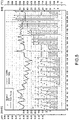
- Figures 3 and 4 include graphics relating, respectively, to the noise tests carried out on pad 1 and on pad 11.
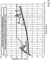
- the Figure 5 graphic contains the friction values recorded on the pad of the invention (INV.) in Figure 1 and on the comparison pad (CONF.) in Figure 2 under different operating conditions (application force of the pad on the disk and speed).
- the pad of the invention ensures the same performance in terms of friction as the comparison pad, despite some friction elements having a lower compressibility modulus. This result makes it possible to lower noise without affecting the efficacy of braking.
- this invention relates to a pad for disc brakes, in which the presence of friction elements made with materials with different compressibility moduli is, surprisingly, able to reduce the noise produced during braking (comparison between Figures 3 and 4 ), without, as a result, encountering the drawbacks relating to low braking efficiency ( Figure 5 ) and a high production of fine powders.
Abstract
Description
- This Patent Application claims priority from
Italian Patent Application No. 102020000028781 filed on November 27, 2020 - This invention relates to a disc brake for railway vehicles. In particular, this invention finds advantageous, but not exclusive, application with low- and medium-speed railway vehicles.
- As is known, disc brakes are subject to great stress and, in order to obtain optimal braking action, it is necessary to have a good transmission of braking force from pad to disk.
- For some time now, the sector has been oriented towards the use of pads comprising multiple friction elements of a smaller size, instead of a single friction element of a larger size. One of the solutions adopted in this regard, requires that each pad mainly consist of a main base plate and multiple friction elements fixed to the base plate. Generally, each of the friction elements is composed of one sheet metal and a friction insert permanently fixed to the sheet metal.
- The solution relating to the use of multiple friction elements of a smaller size is advantageous both in terms of efficacy of pressure on the disk and, thus, of braking, and in terms of low noise. In this regard, it should be highlighted how low noise became an increasingly important discriminating factor in choosing which disc brake to use.
- As can be easily imagined, the need to contain noise during braking is felt most for those trains that make a large number of stops, such as metros, regional trains, or intercity trains.
- Many solutions that lead to a reduction in braking noise suffer from the disadvantage of entailing a lower transmission of braking force from the pad to the disk and, therefore, a reduction in the efficiency of the braking itself. In fact, as is obvious, trains that make many stops (low- and medium-speed trains), even if they do not reach very high speeds, must, in any case, be able to have a high degree of braking efficiency.
- Here and below, the term "low- and medium-speed trains" means those trains whose maximum speed is 220 km/h.
- Another particularly crucial requirement relating to brakes adopted on trains that make many stops, concerns a reduction in pollution in terms of fine dust produced during braking. In fact, the trains considered above repeatedly transit through and stop in areas with high population density, such as residential areas.
- Generally, the solutions that lead to a reduction in braking noise suffer from the disadvantage of entailing a high release of fine powders.
- Thus, the need was felt to provide a type of disc brake for low- and medium-speed trains, the technical features of which were such as to ensure low noise during braking, without, as a result, entailing disadvantages in terms of efficiency of braking and in terms of fine powders produced.
- The inventor of this invention has provided a solution relating to a pad for disc brakes for low- and medium-speed trains, in which the simultaneous presence, according to particular conditions, of friction elements produced with materials with different compressibility moduli ensures that the requirement above is met in a surprising way.
- The subject of this invention is a disc brake for railway vehicles comprising a pad and a disk on which the pad acts; said pad comprising a base plate and multiple friction elements fixed to the base plate; said friction elements comprising first friction elements made of a first material and second friction elements made of a second material; said disc brake being characterized in that said second material has a compressibility modulus (pressure needed to compress the material by 1 mm) smaller than the one of said first material by a value equal or greater to 5 Mpa, preferably 10 MPa; there being a higher number of said first friction elements than of said second friction elements.
- It has been verified that a reduction in noise is already noticeable with a difference of 5 MPa in compressibility modulus. Beyond the difference of 10 MPa of compressibility modulus, the reduction in noise is even clearer.
- Preferably, said friction elements are arranged in arched rows and, in use, basically overlapping with respective concentric lines of the disk on which the pad acts; each arched row comprising both said first friction elements and said second friction elements.
- Preferably, in each of the arched rows, said first friction elements are either equal or greater in number to said second friction elements.
- Preferably, said first material has a compressibility modulus of between 20 and 40 MPa, and said second material has a compressibility modulus of between 2 and 15 MPa.
- Preferably, said first material is a sintered material and said second material is an organic material.
- Preferably, the sintered material has a composition composed of: from 10 to 70% by weight of copper, from 5 to 40% by weight of iron, from 5 to 20% by weight of graphite, from 1 to 10% by weight of friction modifiers.
- Preferably, the organic material has a composition composed of: from 5 to 30% by weight of rubber and resin, from 10 to 50% by weight of filler, from 5 to 20% by weight of graphite, from 5 to 20% by weight of friction modifiers.
- For a better understanding of the invention, one embodiment is included below, merely by way of non-limiting example, with the aid of the attached drawings, wherein:
-
Figure 1 is a view from above, with transparent parts for clarity, of a pad that is the subject of this invention; -
Figure 2 is a view from above, with transparent parts for clarity, of a comparison pad; -
Figure 3 is a graphic that records the noise results as a function of the speed relating to the pad inFigure 1 ; -
Figure 4 is a graphic that records the noise results as a function of the speed relating to the pad inFigure 2 ; -
Figure 5 is a graphic that records the results in terms of friction of the pads respectively inFigure 1 and inFigure 2 . - In
Figure 3 , the reference number 1 indicates, as a whole, a pad for disc brakes according to this invention. - The pad 1 comprises a
base plate 2, adovetail attachment 3 attached to a rear surface of thebase plate 2 and charged with attaching the pad 1 itself to a structure of the disc brake andmultiple friction elements 4 attached to thebase plate 2 and arranged so as to exert pressure on the brake disc to perform the braking action. - For the purposes of this invention, it is irrelevant whether the
friction elements 4 may be attached to theplate 2 temporarily or permanently. - The
friction elements 4 are arranged along the arched rows illustrated in dashed lines and indicated withreference number 5, which, in use, basically overlap with the concentric lines of a disk D on which the pad 1 acts. For simplicity's sake, the disk D is illustrated in dashed lines and only partially. - The
friction elements 4 are divided into: five friction elements made of sinteredmaterial 4b and three friction elements made oforganic material 4a. For clarity's sake, the friction elements made oforganic material 4a are represented by a dashed surface. - The organic material of the
friction elements 4a has a composition that meets the following conditions: from 5 to 30% by weight of rubber and resin, from 10 to 50% by weight of filler, from 5 to 20% by weight of graphite, and from 5 to 20% by weight of friction modifiers. - The organic material has a compressibility modulus of 7 MPa.
- The sintered material of the
friction elements 4b has a composition that meets the following conditions: from 10 to 70% by weight of copper, from 5 to 40% by weight of iron, from 5 to 20% by weight of graphite, from 1 to 10% by weight of friction modifiers. - The sintered material has a compressibility modulus of 27 MPa.
- To measure the compressibility moduli, cylindrical samples were taken perpendicularly to the friction surface that had a diameter of 11.3 mm and a height equal to 10 mm. In this way, the cylinder obtained has a surface of 100 mm2. The samples referred to above, were positioned below the test head of a (Galdabini QUASAR 100-type) traction/compression machine and an increasing force, with a speed of 7.45 daN/s, was applied. The compressibility modulus was calculated in MPa by normalising the compression curve detected on the basis of multiple significant points of the curve itself. The value obtained thus relating to 1 mm of compression was then divided by the area of the cylindrical sample (100 mm2). In contrast to what is described above, the first and the second material may both be sintered materials or both organic materials, as long as they comply with the compressibility modulus conditions contained in the claims.
- The materials with different compressibility moduli may be obtained, not only from materials with different chemical natures, but also via a different preparation process for the same chemical type of material.
- For example, by changing the porousness of the resulting material, it is possible to change its compressibility.
- In
Figure 2 , thereference number 11 indicates, as a whole, a pad for disc brakes according to a comparison example. - The parts of the
second pad 11 that are the same as those of the first pad 1 will be indicated with the same numbering and will not be described again. - The
second pad 11 is differentiated from the first pad 1 due to the fact that all thefriction elements 4 are friction elements made withsintered material 4b. - The first pad 1 and the
second pad 11 were subjected to noise measurements during braking carried out according to the procedure indicated in the UIC 541-3 No. 5B (7th edition) standard and friction tests according to the procedure indicated in the standard UIC 541-3 No. 5B (7th edition). -
Figures 3 and4 include graphics relating, respectively, to the noise tests carried out on pad 1 and onpad 11. - In each of the graphics, there are different curves made with different operating conditions relating to the application forces (pressure) of the pad on disk.
- Of course, in the graphics in
Figures 3 and4 , the curves represented in the same manner were produced with the same application force conditions. - In each of the graphics, there is an admissibility line, which indicates how up to a speed of 80 km/h a braking noise of up to 100 decibel is permitted, while below 60 km/h (the train is likely within the station) a braking noise of up to 90 decibel is permitted.
- It is clear from
Figures 3 and4 how the pad that is the subject of this invention (graphic inFigure 3 ) produces noise consistently below the admissibility line. In contrast, the comparison pad (Figure 4 graphic), in the majority of operating conditions, produces noise above that indicated by the admissibility line for speeds below 60 km/h. - The
Figure 5 graphic contains the friction values recorded on the pad of the invention (INV.) inFigure 1 and on the comparison pad (CONF.) inFigure 2 under different operating conditions (application force of the pad on the disk and speed). - From the
Figure 5 graphic, it is immediately clear how, surprisingly, the pad of the invention ensures the same performance in terms of friction as the comparison pad, despite some friction elements having a lower compressibility modulus. This result makes it possible to lower noise without affecting the efficacy of braking. - In addition, the majority presence of friction elements made with material with a higher compressibility modulus ensures less production of fine powders owing to the friction exerted during the braking action.
- In summary, this invention relates to a pad for disc brakes, in which the presence of friction elements made with materials with different compressibility moduli is, surprisingly, able to reduce the noise produced during braking (comparison between
Figures 3 and4 ), without, as a result, encountering the drawbacks relating to low braking efficiency (Figure 5 ) and a high production of fine powders.
Claims (8)
- A disc brake for railway vehicles comprising a pad (1) and a disk (D) on which the pad (1) acts; said pad (1) comprising a base plate (2) and a plurality of friction elements (4) fixed to the base plate (2); said friction elements (4) comprising first friction elements (4b) made of a first material and second friction elements (4a) made of a second material; said disc brake being characterized in that said second material has a compressibility modulus (pressure needed to compress the material by 1 mm) smaller than the one of said first material by a value equal or greater to 5 MPa; said first friction elements (4b) being in a higher number than said second friction elements (4a).
- The disc brake for railway vehicles according to claim 1, characterized in that said second material has a compressibility modulus smaller than the one of said first material by a value equal or greater to 10 MPa.
- The disc brake for railway vehicles according to claim 1 or 2, characterized in that the friction elements (4) are arranged in rows (5) of arched shape and in use overlapping with respective concentric lines of the disk (D) on which the pad (1) acts; each row (5) of arched shape comprising both said first friction elements (4b) and said second friction elements (4a).
- The disc brake for railway vehicles according to claim 3, characterized in that in each row (5) of arched shape said first friction elements (4b) are in number equal to or greater than said second friction elements (4a).
- The disc brake for railway vehicles according to one of the preceding claims, characterized in that said first material has a compressibility modulus of between 20 and 40 MPa, and said second material has a compressibility modulus of between 2 and 15 MPa.
- The disc brake for railway vehicles according to one of the preceding claims, characterized in that said first material is a sintered material and said second material is an organic material.
- The disc brake for railway vehicles according to claim 6, characterized in that said sintered material has a composition composed of: from 10 to 70% by weight of copper, from 5 to 40% by weight of iron, from 5 to 20% by weight of graphite, from 1 to 10% by weight of friction modifiers.
- The disc brake for railway vehicles according to claim 6 or 7, characterized in that said organic material has a composition composed of: from 5 to 30% by weight of rubber and resin, from 10 to 50% by weight of filler, from 5 to 20% in graphite weight, 5 to 20% by weight of friction modifiers.
Applications Claiming Priority (1)
| Application Number | Priority Date | Filing Date | Title |
|---|---|---|---|
| IT102020000028781A IT202000028781A1 (en) | 2020-11-27 | 2020-11-27 | DISC BRAKE FOR RAILWAY VEHICLES |
Publications (2)
| Publication Number | Publication Date |
|---|---|
| EP4006373A1 true EP4006373A1 (en) | 2022-06-01 |
| EP4006373B1 EP4006373B1 (en) | 2023-01-11 |
Family
ID=74592538
Family Applications (1)
| Application Number | Title | Priority Date | Filing Date |
|---|---|---|---|
| EP21210756.9A Active EP4006373B1 (en) | 2020-11-27 | 2021-11-26 | Disc brake for railway vehicles |
Country Status (8)
| Country | Link |
|---|---|
| US (1) | US20220170523A1 (en) |
| EP (1) | EP4006373B1 (en) |
| KR (1) | KR20220074800A (en) |
| CN (1) | CN114562529A (en) |
| ES (1) | ES2940090T3 (en) |
| FI (1) | FI4006373T3 (en) |
| IT (1) | IT202000028781A1 (en) |
| PT (1) | PT4006373T (en) |
Cited By (1)
| Publication number | Priority date | Publication date | Assignee | Title |
|---|---|---|---|---|
| EP4350164A1 (en) * | 2022-10-06 | 2024-04-10 | Cofren S.r.L. | Disc brake for railway vehicles |
Citations (7)
| Publication number | Priority date | Publication date | Assignee | Title |
|---|---|---|---|---|
| GB2260173A (en) * | 1991-10-01 | 1993-04-07 | Flertex Sa | Disc brake pad for railway use |
| US20070267257A1 (en) * | 2006-05-18 | 2007-11-22 | Okamura Hiromasa | Hybrid pads for disc brakes |
| CN102174946A (en) * | 2011-03-17 | 2011-09-07 | 北京浦然铁路制动科技有限责任公司 | Brake pad of railway vehicle brake device |
| DE102012012876A1 (en) * | 2012-06-06 | 2013-12-12 | Becorit Gmbh | Modular brake pad system and brake pad |
| EP2730798A1 (en) * | 2012-11-07 | 2014-05-14 | Cofren S.r.l. | Railway vehicle disk brake pad |
| CN105909704A (en) * | 2016-01-31 | 2016-08-31 | 张泽伟 | Composite brake pad in excellent thermal diffusivity |
| US20200332848A1 (en) * | 2019-04-18 | 2020-10-22 | Cofren S.R.L. | Pad for disc brakes for railway vehicles |
Family Cites Families (8)
| Publication number | Priority date | Publication date | Assignee | Title |
|---|---|---|---|---|
| US2713923A (en) * | 1952-12-08 | 1955-07-26 | Budd Co | Brake shoe lining for de-icing brake surfaces |
| US3297117A (en) * | 1965-04-30 | 1967-01-10 | Budd Co | Conformable rotary disk brake shoe assembly |
| US4278153A (en) * | 1978-11-24 | 1981-07-14 | Goodyear Aerospace Corporation | Brake friction material with reinforcement material |
| ITRM20050005A1 (en) * | 2005-01-10 | 2006-07-11 | Rutgers Rail S P A | IMPROVED DISC BRAKE SHOE, WITH FRICTION ELEMENTS, IN PARTICULAR FOR RAILWAY USE. |
| IT1396994B1 (en) * | 2009-11-05 | 2012-12-20 | Cofren Srl | IMPROVED SHOE FOR DISC BRAKES FOR RAILWAY AND INDUSTRIAL VEHICLES. |
| JP5333205B2 (en) * | 2009-12-28 | 2013-11-06 | 新日鐵住金株式会社 | Brake lining for railway vehicles |
| DE102014119491A1 (en) * | 2014-12-23 | 2016-06-23 | Knorr-Bremse Systeme für Schienenfahrzeuge GmbH | Brake lining for a partially lined disc brake, arrangement of a brake pad on a pad holder and method for actuating a brake pad supported on a pad holder |
| DE102018216268A1 (en) * | 2017-09-29 | 2019-04-04 | Robert Bosch Gmbh | ADDITIVELY MANUFACTURED BRAKE LINE ARRANGEMENT WITH CONTROLLED COMPRESSIBILITY FACTOR |
-
2020
- 2020-11-27 IT IT102020000028781A patent/IT202000028781A1/en unknown
-
2021
- 2021-11-23 US US17/534,110 patent/US20220170523A1/en active Pending
- 2021-11-25 CN CN202111413264.6A patent/CN114562529A/en active Pending
- 2021-11-26 ES ES21210756T patent/ES2940090T3/en active Active
- 2021-11-26 FI FIEP21210756.9T patent/FI4006373T3/en active
- 2021-11-26 PT PT212107569T patent/PT4006373T/en unknown
- 2021-11-26 EP EP21210756.9A patent/EP4006373B1/en active Active
- 2021-11-29 KR KR1020210166947A patent/KR20220074800A/en unknown
Patent Citations (7)
| Publication number | Priority date | Publication date | Assignee | Title |
|---|---|---|---|---|
| GB2260173A (en) * | 1991-10-01 | 1993-04-07 | Flertex Sa | Disc brake pad for railway use |
| US20070267257A1 (en) * | 2006-05-18 | 2007-11-22 | Okamura Hiromasa | Hybrid pads for disc brakes |
| CN102174946A (en) * | 2011-03-17 | 2011-09-07 | 北京浦然铁路制动科技有限责任公司 | Brake pad of railway vehicle brake device |
| DE102012012876A1 (en) * | 2012-06-06 | 2013-12-12 | Becorit Gmbh | Modular brake pad system and brake pad |
| EP2730798A1 (en) * | 2012-11-07 | 2014-05-14 | Cofren S.r.l. | Railway vehicle disk brake pad |
| CN105909704A (en) * | 2016-01-31 | 2016-08-31 | 张泽伟 | Composite brake pad in excellent thermal diffusivity |
| US20200332848A1 (en) * | 2019-04-18 | 2020-10-22 | Cofren S.R.L. | Pad for disc brakes for railway vehicles |
Cited By (1)
| Publication number | Priority date | Publication date | Assignee | Title |
|---|---|---|---|---|
| EP4350164A1 (en) * | 2022-10-06 | 2024-04-10 | Cofren S.r.L. | Disc brake for railway vehicles |
Also Published As
| Publication number | Publication date |
|---|---|
| KR20220074800A (en) | 2022-06-03 |
| US20220170523A1 (en) | 2022-06-02 |
| PT4006373T (en) | 2023-04-04 |
| FI4006373T3 (en) | 2023-04-06 |
| ES2940090T3 (en) | 2023-05-03 |
| IT202000028781A1 (en) | 2022-05-27 |
| CN114562529A (en) | 2022-05-31 |
| EP4006373B1 (en) | 2023-01-11 |
Similar Documents
| Publication | Publication Date | Title |
|---|---|---|
| EP4006373A1 (en) | Disc brake for railway vehicles | |
| KR101754299B1 (en) | Railroad and industrial vehicle disk brake pad | |
| KR20140013094A (en) | Brake lining for railway vehicles and disc brakes equipped with same | |
| DE102013201389A1 (en) | Friction brake with resistance sensor | |
| US4672082A (en) | Friction material using steel fibers | |
| JPS5839557A (en) | Main suspension system for railway rolling stock | |
| US4156479A (en) | Disc for a vehicle disc-brake | |
| RU180717U1 (en) | FRICTION ELEMENT FOR BRAKE RINKER BRAKE TIRE | |
| ATE185406T1 (en) | DISC BRAKE PADS FOR RAIL VEHICLES | |
| CA2545038C (en) | Friction wedge with mechanical bonding matrix augmented composition liner material | |
| US11668361B2 (en) | Vehicle disc/brake system | |
| CN209294293U (en) | A kind of high bond strength brake block | |
| US20220325763A1 (en) | Vehicle disc brake | |
| CN216382321U (en) | Brake block and vehicle | |
| US20240117849A1 (en) | Disc brake for railway vehicles | |
| CN212744785U (en) | Shock-absorbing structure for automobile brake pad | |
| CN212225835U (en) | High-speed train braking system integrating interface, loading optimization and fault monitoring | |
| IT201900015309A1 (en) | PAD FOR DISC BRAKES FOR MEDIUM / LOW SPEED RAILWAY VEHICLES | |
| AT513194A1 (en) | Brake system for a rail vehicle and rail vehicle with such braking system | |
| DE102022204579A1 (en) | Brake block for a disc brake system and disc brake system | |
| CN111322334A (en) | High-speed train braking system integrating interface, loading optimization and fault monitoring | |
| CN112356810A (en) | Brake mechanism for automobile | |
| EP0763669A1 (en) | Brake shoe for disc brake with audible warning device | |
| JPH0517739A (en) | Frictional material | |
| DE2535201A1 (en) | Disc brakes for motor vehicles - has brake lining wear warning indicator with projection fitting below brake shoe |
Legal Events
| Date | Code | Title | Description |
|---|---|---|---|
| PUAI | Public reference made under article 153(3) epc to a published international application that has entered the european phase |
Free format text: ORIGINAL CODE: 0009012 |
|
| STAA | Information on the status of an ep patent application or granted ep patent |
Free format text: STATUS: THE APPLICATION HAS BEEN PUBLISHED |
|
| AK | Designated contracting states |
Kind code of ref document: A1 Designated state(s): AL AT BE BG CH CY CZ DE DK EE ES FI FR GB GR HR HU IE IS IT LI LT LU LV MC MK MT NL NO PL PT RO RS SE SI SK SM TR |
|
| STAA | Information on the status of an ep patent application or granted ep patent |
Free format text: STATUS: REQUEST FOR EXAMINATION WAS MADE |
|
| 17P | Request for examination filed |
Effective date: 20220608 |
|
| RBV | Designated contracting states (corrected) |
Designated state(s): AL AT BE BG CH CY CZ DE DK EE ES FI FR GB GR HR HU IE IS IT LI LT LU LV MC MK MT NL NO PL PT RO RS SE SI SK SM TR |
|
| RIC1 | Information provided on ipc code assigned before grant |
Ipc: F16D 65/12 20060101ALI20220623BHEP Ipc: F16D 65/00 20060101AFI20220623BHEP |
|
| GRAP | Despatch of communication of intention to grant a patent |
Free format text: ORIGINAL CODE: EPIDOSNIGR1 |
|
| STAA | Information on the status of an ep patent application or granted ep patent |
Free format text: STATUS: GRANT OF PATENT IS INTENDED |
|
| INTG | Intention to grant announced |
Effective date: 20220803 |
|
| GRAS | Grant fee paid |
Free format text: ORIGINAL CODE: EPIDOSNIGR3 |
|
| GRAA | (expected) grant |
Free format text: ORIGINAL CODE: 0009210 |
|
| STAA | Information on the status of an ep patent application or granted ep patent |
Free format text: STATUS: THE PATENT HAS BEEN GRANTED |
|
| AK | Designated contracting states |
Kind code of ref document: B1 Designated state(s): AL AT BE BG CH CY CZ DE DK EE ES FI FR GB GR HR HU IE IS IT LI LT LU LV MC MK MT NL NO PL PT RO RS SE SI SK SM TR |
|
| REG | Reference to a national code |
Ref country code: GB Ref legal event code: FG4D |
|
| REG | Reference to a national code |
Ref country code: CH Ref legal event code: EP |
|
| REG | Reference to a national code |
Ref country code: DE Ref legal event code: R096 Ref document number: 602021001217 Country of ref document: DE |
|
| REG | Reference to a national code |
Ref country code: IE Ref legal event code: FG4D |
|
| REG | Reference to a national code |
Ref country code: AT Ref legal event code: REF Ref document number: 1543604 Country of ref document: AT Kind code of ref document: T Effective date: 20230215 |
|
| REG | Reference to a national code |
Ref country code: PT Ref legal event code: SC4A Ref document number: 4006373 Country of ref document: PT Date of ref document: 20230404 Kind code of ref document: T Free format text: AVAILABILITY OF NATIONAL TRANSLATION Effective date: 20230330 |
|
| REG | Reference to a national code |
Ref country code: ES Ref legal event code: FG2A Ref document number: 2940090 Country of ref document: ES Kind code of ref document: T3 Effective date: 20230503 |
|
| REG | Reference to a national code |
Ref country code: LT Ref legal event code: MG9D |
|
| REG | Reference to a national code |
Ref country code: NL Ref legal event code: MP Effective date: 20230111 |
|
| PG25 | Lapsed in a contracting state [announced via postgrant information from national office to epo] |
Ref country code: NL Free format text: LAPSE BECAUSE OF FAILURE TO SUBMIT A TRANSLATION OF THE DESCRIPTION OR TO PAY THE FEE WITHIN THE PRESCRIBED TIME-LIMIT Effective date: 20230111 |
|
| P01 | Opt-out of the competence of the unified patent court (upc) registered |
Effective date: 20230616 |
|
| PG25 | Lapsed in a contracting state [announced via postgrant information from national office to epo] |
Ref country code: RS Free format text: LAPSE BECAUSE OF FAILURE TO SUBMIT A TRANSLATION OF THE DESCRIPTION OR TO PAY THE FEE WITHIN THE PRESCRIBED TIME-LIMIT Effective date: 20230111 Ref country code: NO Free format text: LAPSE BECAUSE OF FAILURE TO SUBMIT A TRANSLATION OF THE DESCRIPTION OR TO PAY THE FEE WITHIN THE PRESCRIBED TIME-LIMIT Effective date: 20230411 Ref country code: LV Free format text: LAPSE BECAUSE OF FAILURE TO SUBMIT A TRANSLATION OF THE DESCRIPTION OR TO PAY THE FEE WITHIN THE PRESCRIBED TIME-LIMIT Effective date: 20230111 Ref country code: LT Free format text: LAPSE BECAUSE OF FAILURE TO SUBMIT A TRANSLATION OF THE DESCRIPTION OR TO PAY THE FEE WITHIN THE PRESCRIBED TIME-LIMIT Effective date: 20230111 Ref country code: HR Free format text: LAPSE BECAUSE OF FAILURE TO SUBMIT A TRANSLATION OF THE DESCRIPTION OR TO PAY THE FEE WITHIN THE PRESCRIBED TIME-LIMIT Effective date: 20230111 |
|
| PG25 | Lapsed in a contracting state [announced via postgrant information from national office to epo] |
Ref country code: SE Free format text: LAPSE BECAUSE OF FAILURE TO SUBMIT A TRANSLATION OF THE DESCRIPTION OR TO PAY THE FEE WITHIN THE PRESCRIBED TIME-LIMIT Effective date: 20230111 Ref country code: PL Free format text: LAPSE BECAUSE OF FAILURE TO SUBMIT A TRANSLATION OF THE DESCRIPTION OR TO PAY THE FEE WITHIN THE PRESCRIBED TIME-LIMIT Effective date: 20230111 Ref country code: IS Free format text: LAPSE BECAUSE OF FAILURE TO SUBMIT A TRANSLATION OF THE DESCRIPTION OR TO PAY THE FEE WITHIN THE PRESCRIBED TIME-LIMIT Effective date: 20230511 Ref country code: GR Free format text: LAPSE BECAUSE OF FAILURE TO SUBMIT A TRANSLATION OF THE DESCRIPTION OR TO PAY THE FEE WITHIN THE PRESCRIBED TIME-LIMIT Effective date: 20230412 |
|
| REG | Reference to a national code |
Ref country code: DE Ref legal event code: R097 Ref document number: 602021001217 Country of ref document: DE |
|
| PG25 | Lapsed in a contracting state [announced via postgrant information from national office to epo] |
Ref country code: SM Free format text: LAPSE BECAUSE OF FAILURE TO SUBMIT A TRANSLATION OF THE DESCRIPTION OR TO PAY THE FEE WITHIN THE PRESCRIBED TIME-LIMIT Effective date: 20230111 Ref country code: RO Free format text: LAPSE BECAUSE OF FAILURE TO SUBMIT A TRANSLATION OF THE DESCRIPTION OR TO PAY THE FEE WITHIN THE PRESCRIBED TIME-LIMIT Effective date: 20230111 Ref country code: EE Free format text: LAPSE BECAUSE OF FAILURE TO SUBMIT A TRANSLATION OF THE DESCRIPTION OR TO PAY THE FEE WITHIN THE PRESCRIBED TIME-LIMIT Effective date: 20230111 Ref country code: DK Free format text: LAPSE BECAUSE OF FAILURE TO SUBMIT A TRANSLATION OF THE DESCRIPTION OR TO PAY THE FEE WITHIN THE PRESCRIBED TIME-LIMIT Effective date: 20230111 Ref country code: CZ Free format text: LAPSE BECAUSE OF FAILURE TO SUBMIT A TRANSLATION OF THE DESCRIPTION OR TO PAY THE FEE WITHIN THE PRESCRIBED TIME-LIMIT Effective date: 20230111 |
|
| PLBE | No opposition filed within time limit |
Free format text: ORIGINAL CODE: 0009261 |
|
| STAA | Information on the status of an ep patent application or granted ep patent |
Free format text: STATUS: NO OPPOSITION FILED WITHIN TIME LIMIT |
|
| PG25 | Lapsed in a contracting state [announced via postgrant information from national office to epo] |
Ref country code: SK Free format text: LAPSE BECAUSE OF FAILURE TO SUBMIT A TRANSLATION OF THE DESCRIPTION OR TO PAY THE FEE WITHIN THE PRESCRIBED TIME-LIMIT Effective date: 20230111 |
|
| REG | Reference to a national code |
Ref country code: AT Ref legal event code: UEP Ref document number: 1543604 Country of ref document: AT Kind code of ref document: T Effective date: 20230111 |
|
| 26N | No opposition filed |
Effective date: 20231012 |
|
| PGFP | Annual fee paid to national office [announced via postgrant information from national office to epo] |
Ref country code: ES Payment date: 20231213 Year of fee payment: 3 |
|
| PG25 | Lapsed in a contracting state [announced via postgrant information from national office to epo] |
Ref country code: SI Free format text: LAPSE BECAUSE OF FAILURE TO SUBMIT A TRANSLATION OF THE DESCRIPTION OR TO PAY THE FEE WITHIN THE PRESCRIBED TIME-LIMIT Effective date: 20230111 |
|
| PGFP | Annual fee paid to national office [announced via postgrant information from national office to epo] |
Ref country code: TR Payment date: 20231120 Year of fee payment: 3 Ref country code: PT Payment date: 20231120 Year of fee payment: 3 Ref country code: IT Payment date: 20231130 Year of fee payment: 3 Ref country code: FR Payment date: 20231129 Year of fee payment: 3 Ref country code: FI Payment date: 20231122 Year of fee payment: 3 Ref country code: DE Payment date: 20231128 Year of fee payment: 3 |