EP4006360A1 - Redundante hydraulikaggregatarchitektur für das hauptfahrwerk eines flugzeugs - Google Patents
Redundante hydraulikaggregatarchitektur für das hauptfahrwerk eines flugzeugs Download PDFInfo
- Publication number
- EP4006360A1 EP4006360A1 EP21210862.5A EP21210862A EP4006360A1 EP 4006360 A1 EP4006360 A1 EP 4006360A1 EP 21210862 A EP21210862 A EP 21210862A EP 4006360 A1 EP4006360 A1 EP 4006360A1
- Authority
- EP
- European Patent Office
- Prior art keywords
- main landing
- power pack
- landing gear
- interface
- load
- Prior art date
- Legal status (The legal status is an assumption and is not a legal conclusion. Google has not performed a legal analysis and makes no representation as to the accuracy of the status listed.)
- Granted
Links
- 239000012530 fluid Substances 0.000 claims description 105
- 238000000034 method Methods 0.000 claims description 7
- 230000007704 transition Effects 0.000 claims description 6
- 230000008878 coupling Effects 0.000 claims description 3
- 238000010168 coupling process Methods 0.000 claims description 3
- 238000005859 coupling reaction Methods 0.000 claims description 3
- 238000006073 displacement reaction Methods 0.000 claims description 3
- 238000011144 upstream manufacturing Methods 0.000 claims description 2
- 206010049933 Hypophosphatasia Diseases 0.000 abstract 1
- 238000010586 diagram Methods 0.000 description 5
- 238000012986 modification Methods 0.000 description 2
- 230000004048 modification Effects 0.000 description 2
- 238000012544 monitoring process Methods 0.000 description 1
- 230000008569 process Effects 0.000 description 1
- 238000000926 separation method Methods 0.000 description 1
- 238000012546 transfer Methods 0.000 description 1
- 238000010792 warming Methods 0.000 description 1
Images


Classifications
-
- F—MECHANICAL ENGINEERING; LIGHTING; HEATING; WEAPONS; BLASTING
- F15—FLUID-PRESSURE ACTUATORS; HYDRAULICS OR PNEUMATICS IN GENERAL
- F15B—SYSTEMS ACTING BY MEANS OF FLUIDS IN GENERAL; FLUID-PRESSURE ACTUATORS, e.g. SERVOMOTORS; DETAILS OF FLUID-PRESSURE SYSTEMS, NOT OTHERWISE PROVIDED FOR
- F15B11/00—Servomotor systems without provision for follow-up action; Circuits therefor
- F15B11/16—Servomotor systems without provision for follow-up action; Circuits therefor with two or more servomotors
- F15B11/17—Servomotor systems without provision for follow-up action; Circuits therefor with two or more servomotors using two or more pumps
-
- B—PERFORMING OPERATIONS; TRANSPORTING
- B64—AIRCRAFT; AVIATION; COSMONAUTICS
- B64C—AEROPLANES; HELICOPTERS
- B64C25/00—Alighting gear
- B64C25/02—Undercarriages
- B64C25/08—Undercarriages non-fixed, e.g. jettisonable
- B64C25/10—Undercarriages non-fixed, e.g. jettisonable retractable, foldable, or the like
- B64C25/18—Operating mechanisms
- B64C25/22—Operating mechanisms fluid
-
- F—MECHANICAL ENGINEERING; LIGHTING; HEATING; WEAPONS; BLASTING
- F15—FLUID-PRESSURE ACTUATORS; HYDRAULICS OR PNEUMATICS IN GENERAL
- F15B—SYSTEMS ACTING BY MEANS OF FLUIDS IN GENERAL; FLUID-PRESSURE ACTUATORS, e.g. SERVOMOTORS; DETAILS OF FLUID-PRESSURE SYSTEMS, NOT OTHERWISE PROVIDED FOR
- F15B1/00—Installations or systems with accumulators; Supply reservoir or sump assemblies
- F15B1/26—Supply reservoir or sump assemblies
-
- F—MECHANICAL ENGINEERING; LIGHTING; HEATING; WEAPONS; BLASTING
- F15—FLUID-PRESSURE ACTUATORS; HYDRAULICS OR PNEUMATICS IN GENERAL
- F15B—SYSTEMS ACTING BY MEANS OF FLUIDS IN GENERAL; FLUID-PRESSURE ACTUATORS, e.g. SERVOMOTORS; DETAILS OF FLUID-PRESSURE SYSTEMS, NOT OTHERWISE PROVIDED FOR
- F15B13/00—Details of servomotor systems ; Valves for servomotor systems
- F15B13/02—Fluid distribution or supply devices characterised by their adaptation to the control of servomotors
- F15B13/028—Shuttle valves
-
- F—MECHANICAL ENGINEERING; LIGHTING; HEATING; WEAPONS; BLASTING
- F15—FLUID-PRESSURE ACTUATORS; HYDRAULICS OR PNEUMATICS IN GENERAL
- F15B—SYSTEMS ACTING BY MEANS OF FLUIDS IN GENERAL; FLUID-PRESSURE ACTUATORS, e.g. SERVOMOTORS; DETAILS OF FLUID-PRESSURE SYSTEMS, NOT OTHERWISE PROVIDED FOR
- F15B19/00—Testing; Calibrating; Fault detection or monitoring; Simulation or modelling of fluid-pressure systems or apparatus not otherwise provided for
-
- F—MECHANICAL ENGINEERING; LIGHTING; HEATING; WEAPONS; BLASTING
- F15—FLUID-PRESSURE ACTUATORS; HYDRAULICS OR PNEUMATICS IN GENERAL
- F15B—SYSTEMS ACTING BY MEANS OF FLUIDS IN GENERAL; FLUID-PRESSURE ACTUATORS, e.g. SERVOMOTORS; DETAILS OF FLUID-PRESSURE SYSTEMS, NOT OTHERWISE PROVIDED FOR
- F15B20/00—Safety arrangements for fluid actuator systems; Applications of safety devices in fluid actuator systems; Emergency measures for fluid actuator systems
- F15B20/004—Fluid pressure supply failure
-
- F—MECHANICAL ENGINEERING; LIGHTING; HEATING; WEAPONS; BLASTING
- F15—FLUID-PRESSURE ACTUATORS; HYDRAULICS OR PNEUMATICS IN GENERAL
- F15B—SYSTEMS ACTING BY MEANS OF FLUIDS IN GENERAL; FLUID-PRESSURE ACTUATORS, e.g. SERVOMOTORS; DETAILS OF FLUID-PRESSURE SYSTEMS, NOT OTHERWISE PROVIDED FOR
- F15B2211/00—Circuits for servomotor systems
- F15B2211/20—Fluid pressure source, e.g. accumulator or variable axial piston pump
- F15B2211/205—Systems with pumps
- F15B2211/20576—Systems with pumps with multiple pumps
-
- F—MECHANICAL ENGINEERING; LIGHTING; HEATING; WEAPONS; BLASTING
- F15—FLUID-PRESSURE ACTUATORS; HYDRAULICS OR PNEUMATICS IN GENERAL
- F15B—SYSTEMS ACTING BY MEANS OF FLUIDS IN GENERAL; FLUID-PRESSURE ACTUATORS, e.g. SERVOMOTORS; DETAILS OF FLUID-PRESSURE SYSTEMS, NOT OTHERWISE PROVIDED FOR
- F15B2211/00—Circuits for servomotor systems
- F15B2211/30—Directional control
- F15B2211/305—Directional control characterised by the type of valves
- F15B2211/3056—Assemblies of multiple valves
- F15B2211/3059—Assemblies of multiple valves having multiple valves for multiple output members
- F15B2211/30595—Assemblies of multiple valves having multiple valves for multiple output members with additional valves between the groups of valves for multiple output members
-
- F—MECHANICAL ENGINEERING; LIGHTING; HEATING; WEAPONS; BLASTING
- F15—FLUID-PRESSURE ACTUATORS; HYDRAULICS OR PNEUMATICS IN GENERAL
- F15B—SYSTEMS ACTING BY MEANS OF FLUIDS IN GENERAL; FLUID-PRESSURE ACTUATORS, e.g. SERVOMOTORS; DETAILS OF FLUID-PRESSURE SYSTEMS, NOT OTHERWISE PROVIDED FOR
- F15B2211/00—Circuits for servomotor systems
- F15B2211/40—Flow control
- F15B2211/42—Flow control characterised by the type of actuation
- F15B2211/426—Flow control characterised by the type of actuation electrically or electronically
-
- F—MECHANICAL ENGINEERING; LIGHTING; HEATING; WEAPONS; BLASTING
- F15—FLUID-PRESSURE ACTUATORS; HYDRAULICS OR PNEUMATICS IN GENERAL
- F15B—SYSTEMS ACTING BY MEANS OF FLUIDS IN GENERAL; FLUID-PRESSURE ACTUATORS, e.g. SERVOMOTORS; DETAILS OF FLUID-PRESSURE SYSTEMS, NOT OTHERWISE PROVIDED FOR
- F15B2211/00—Circuits for servomotor systems
- F15B2211/60—Circuit components or control therefor
- F15B2211/63—Electronic controllers
- F15B2211/6303—Electronic controllers using input signals
- F15B2211/6306—Electronic controllers using input signals representing a pressure
- F15B2211/6309—Electronic controllers using input signals representing a pressure the pressure being a pressure source supply pressure
-
- F—MECHANICAL ENGINEERING; LIGHTING; HEATING; WEAPONS; BLASTING
- F15—FLUID-PRESSURE ACTUATORS; HYDRAULICS OR PNEUMATICS IN GENERAL
- F15B—SYSTEMS ACTING BY MEANS OF FLUIDS IN GENERAL; FLUID-PRESSURE ACTUATORS, e.g. SERVOMOTORS; DETAILS OF FLUID-PRESSURE SYSTEMS, NOT OTHERWISE PROVIDED FOR
- F15B2211/00—Circuits for servomotor systems
- F15B2211/70—Output members, e.g. hydraulic motors or cylinders or control therefor
- F15B2211/71—Multiple output members, e.g. multiple hydraulic motors or cylinders
- F15B2211/7142—Multiple output members, e.g. multiple hydraulic motors or cylinders the output members being arranged in multiple groups
-
- F—MECHANICAL ENGINEERING; LIGHTING; HEATING; WEAPONS; BLASTING
- F15—FLUID-PRESSURE ACTUATORS; HYDRAULICS OR PNEUMATICS IN GENERAL
- F15B—SYSTEMS ACTING BY MEANS OF FLUIDS IN GENERAL; FLUID-PRESSURE ACTUATORS, e.g. SERVOMOTORS; DETAILS OF FLUID-PRESSURE SYSTEMS, NOT OTHERWISE PROVIDED FOR
- F15B2211/00—Circuits for servomotor systems
- F15B2211/80—Other types of control related to particular problems or conditions
- F15B2211/86—Control during or prevention of abnormal conditions
- F15B2211/863—Control during or prevention of abnormal conditions the abnormal condition being a hydraulic or pneumatic failure
- F15B2211/8633—Pressure source supply failure
-
- F—MECHANICAL ENGINEERING; LIGHTING; HEATING; WEAPONS; BLASTING
- F15—FLUID-PRESSURE ACTUATORS; HYDRAULICS OR PNEUMATICS IN GENERAL
- F15B—SYSTEMS ACTING BY MEANS OF FLUIDS IN GENERAL; FLUID-PRESSURE ACTUATORS, e.g. SERVOMOTORS; DETAILS OF FLUID-PRESSURE SYSTEMS, NOT OTHERWISE PROVIDED FOR
- F15B2211/00—Circuits for servomotor systems
- F15B2211/80—Other types of control related to particular problems or conditions
- F15B2211/875—Control measures for coping with failures
- F15B2211/8757—Control measures for coping with failures using redundant components or assemblies
Definitions
- Many aircraft actuation systems are powered by a hydraulic system including high pressure and low pressure lines connecting a reservoir (i.e., a tank), a pump, filters, sensors, and at least one load (consisting of valves, actuators, etc.).
- a reservoir i.e., a tank
- a pump filters, sensors, and at least one load (consisting of valves, actuators, etc.).
- deployment and retraction of the main landing gear system of an aircraft may be powered by the hydraulic system.
- the main landing gear system includes a left main landing gear and a right main landing gear.
- a traditional hydraulic system includes a reservoir, pump, and other components sized to power both the left and right main landing gears.
- a second hydraulic system of the same size and configuration is provided to take over in case of failure of the first hydraulic system.
- the hydraulic system includes a first hydraulic power pack sized to service one of the main landing gears (e.g., the left main landing gear), a second hydraulic power pack sized to service another of the main landing gears (e.g., the right main landing gear), and a backup valve arrangement configured to connect together the high pressure lines and the low pressure lines of the first and second hydraulic power packs to allow one of the first and second hydraulic power packs to service both the left and right main landing gears.
- the hydraulic system includes a hydraulic power pack including a pump, a high pressure line extending from the pump, and a return line disposed within a body.
- the return line extends towards a tank.
- the body defines a first pressure port receiving the high pressure line from the pump, a first return port fluidly coupled to the return line, and a second return port also fluidly coupled to the return line.
- inventive aspects can relate to individual features and to combinations of features. It is to be understood that both the forgoing general description and the following detailed description are exemplary and explanatory only and are not restrictive of the broad inventive concepts upon which the embodiments disclosed herein are based.
- the present disclosure is directed to a distributed hydraulic power system 100 for use on an aircraft.
- the distributed hydraulic power system 100 can be used to deploy the main landing gear of the aircraft, which includes a left main landing gear and a right main landing gear.
- the distributed hydraulic power system 100 provides redundancy in case of failure in the hydraulic power system, but without the weight of a traditional system.
- Each of the left and right main landing gears is controlled by a respective actuation system 102, 104.
- Each actuation system 102, 104 includes one or more control valves and actuators to lower and raise the main wheels, actuate locks, open doors providing selective access to the wheels, or otherwise contribute the deploying and/or retracting the main landing gear.
- the actuation systems 102, 104 each include a switch valve arrangement that controls how the high pressure fluid is applied to the actuator(s) in the actuation systems 102, 104 to switch between deployment and retraction.
- the distributed hydraulic power system 100 includes a first power pack 110A, a second power pack 110B, and a backup valve arrangement 140.
- the first power pack 110A is configured to provide high pressure fluid (i.e., power) to an actuation system 102 of the left main landing gear via a high pressure line 132A and to receive low pressure fluid back from the left main landing gear actuation system 102 via a low pressure line 134A.
- the second power pack 110B is configured to provide high pressure fluid to an actuation system 104 of the right main landing gear via a high pressure line 132B and to receive low pressure fluid back from the right main landing gear actuation system 104 via a low pressure line 134B.
- the first power pack 110A is identical to the second power pack 110B.
- Each power pack 110A, 110B is sized (e.g., a respective reservoir and pump of the power pack is sized) to provide sufficient power to operate one of the main landing gear actuation systems 102, 104 within a first deployment time frame (e.g., 8 seconds, 12 seconds, 16 seconds, etc.) and a first retraction time frame (e.g., 8 seconds, 12 seconds, sixteen seconds, etc.).
- each power pack 110A, 110B is sized to operate only one of the actuation systems 102, 104 within the first deployment and retraction time frames.
- each power pack 110A, 110B is sized to provide sufficient power to both of the main landing gear actuation systems 102, 104 within a second deployment time frame and a second retraction time frame.
- the second deployment time frame is longer than the first deployment time frame, but still short enough to safely deploy the main landing gear during landing of the aircraft.
- the second retraction time frame is longer than the first retraction time frame, but still short enough to safely retract the main landing gear during take-off of the aircraft.
- the second time frame is at least 1.2 times as long as the first time frame. In certain implementations, the second time frame is at least 1.5 times as long as the first time frame. In certain implementations, the second time frame is at least 1.8 times as long as the first time frame. In certain implementations, the second time frame is twice as long as the first time frame. In certain implementations, the second time frame is three times as long as the first time frame. In certain implementations, the second time frame is between 1.2 times and three times as long as the first time frame. In certain implementations, the second time frame is between 1.5 times and twice as long as the first time frame. In certain implementations, the second time frame is between 1.2 times and twice as long as the first time frame.
- each power pack 110A, 110B can be configured to operate both main landing gear actuation systems 102, 104 at full performance rate (i.e., can operate both systems 102, 104 within the first deployment time frame and the first retraction time frame).
- each power pack 110A, 110B can be configured to be
- the first power pack 110A provides power to the left main landing gear actuation system 102 while the second power pack 110B concurrently provides power to the right main landing gear actuator 104.
- a backup valve arrangement 140 remains closed during normal use, thereby maintaining separation of the first and second power packs 110A, 110B.
- the backup valve arrangement 140 is opened to connect the still functioning power pack to both of the left and right main landing gear actuation systems 102, 104, concurrently.
- FIG. 2 shows an example implementation of a hydraulic power pack 110 suitable for use as both the first power pack 110A and the second power pack 110B of FIG. 1 .
- the hydraulic power pack 110 includes a body 111 having a load interface 112 and a first tank return interface 114 through which the power pack 110 can be fluidly coupled to the respective main landing gear actuation system 102, 104.
- the power pack 110 includes a reservoir 118 disposed within the power pack body 111.
- the reservoir 118 is sized to hold a sufficient amount of fluid to power the respective main landing gear actuator 102, 104.
- the internal lines within the power pack body 111 can be fluidly coupled to an external reservoir via a tank interface defined through the power pack body 111.
- a low pressure line 123 fluidly couples the first return interface 114 to the internal reservoir 118 or tank interface.
- the power pack body 111 also defines a second tank return interface 116 that is fluidly coupled to the internal reservoir 118 or tank interface.
- the second return interface 116 is fluidly coupled to the low pressure line 123.
- no filter modules are disposed between the second return interface 116 and the reservoir 118 or tank interface.
- each interface 112, 114, 116 allows an external fluid conduit (e.g., a tube, pipe, hose, etc.) to connect to an internal fluid line within the power pack 110.
- each interface 112, 114, 116 may provide attachment structure (e.g., threads, clamping surfaces, etc.) at which the fluid conduits can be attached to the power pack body 111.
- each interface 112, 114, 116 can provide a sealed port through which a fluid conduit can extend through a wall of the power pack body 111 to define at least a portion of both the respective internal fluid line and the respective external fluid line.
- the power pack 110 includes a pump 120 configured to draw fluid from the reservoir 118 (or external reservoir), to pressurize the fluid, and to direct the high pressure fluid over a high pressure line 121 to the first load interface 112.
- the pump 120 is driven by a motor 122, which is controlled by an aircraft operating system via a respective motor controller 106, 108.
- the pump 120 includes a fixed displacement pump 120 driven by a variable speed motor pump 122.
- Low pressure fluid is returned to the power pack 110 from the respective main landing gear actuator 102, 104 via the first return interface 114. The low pressure fluid travels over a low pressure line 123 from the first return interface 114 to the reservoir 118.
- a high pressure filter module 124 is fluidly disposed between an output of the pump 120 and the load interface 112. Accordingly, all of the high pressure fluid is filtered before reaching the respective main landing gear 102, 104.
- a low pressure filter module 126 is fluidly disposed between the first return interface 114 and the reservoir 118. Accordingly, the low pressure fluid may be filtered again upon returning from the respective main landing gear actuator 102, 104.
- the low pressure filter module 126 includes a bypass around the low pressure filter module 126.
- the power pack 110 also includes a bypass or warming restrictor 130 that connects the high pressure line 121 to the reservoir 118 within the power pack body 111.
- the bypass restrictor 130 has a restricted passage that limits the amount of fluid that can travel therebetween. Accordingly, a small amount of high pressure fluid can return to the reservoir 118.
- the power pack 110 includes a high pressure relief valve 125 between the high pressure line 121 and the reservoir 118. The valve 125 relieves the pressure in the high pressure line 121 if the pressure climbs above a predetermined maximum operating pressure.
- various sensors are disposed within the power pack 110 to monitor the pressure, temperature, and/or other characteristics of the fluid flowing through the power pack 110.
- a pressure transducer 128 may be fluidly coupled to the high pressure line 121 to sense a pressure of the fluid within the high pressure line 121.
- the pressure transducer 128 is disposed downstream from the output of the pump 120.
- the pressure transducer 128 is disposed downstream from the high pressure filter module 124. Accordingly, the pressure transducer 128 may sense when pressure is lost either at the pump 120 or at the high pressure filter module 124.
- the various sensors also include a pressure transducer 119 at the reservoir 118.
- the pressure transducer 119 is a pressure and temperature transducer that measures both the pressure and the temperature of the low pressure fluid within the reservoir 118.
- each power pack 110A, 110B is fluidly coupled to the backup valve arrangement 140 via an external high pressure line 136A, 136B and an external low pressure line 138A, 138B.
- the low pressure line 138A, 138B is fluidly coupled to the internal low pressure line 123 at the second return interface 116 of the respective power pack 110A, 110B.
- the external low pressure lines 138A, 138B and the internal low pressure line 123 are formed by a common fluid conduit that extends through the second return interface 116.
- the external high pressure lines 136A, 136B fluidly couple to the high pressure lines 132A, 132B, respectively, outside the respective power pack body 111.
- the external high pressure line 136A, 136B may pass through the respective body 111 at a separate port (not shown) to fluidly couple to the internal high pressure line 121 within the power pack body 111.
- each motor controller 106, 108 is operated independent of the other.
- each motor controller 106, 108 is configured to receive data from the sensors 128, 119 of the respective power pack 110A, 110B.
- each motor controller 106, 108 is powered by a respective power source E1, E2.
- FIG. 3 shows an example implementation of a backup valve arrangement 140 suitable for use in selectively coupling one of the power packs 110A, 110B to both main landing gear actuators 102, 104 in the event of a failure of the other one of the power packs 110A, 110B.
- the backup valve arrangement 140 includes a valve spool 150 having an open position and a closed position.
- the valve spool 150 selectively couples together the external high pressure lines 136A, 136B from the first and second power packs 110A, 110B when in the open position.
- the valve spool 150 also selectively couples together the external low pressure lines 138A, 138B from the first and second power packs 110A, 110B when in the open position.
- the valve spool 150 decouples the high pressure lines 136A, 13B and decouples the low pressure lines 138A, 138B.
- the valve spool 150 is biased to the closed position.
- movement of the valve spool 150 between the open and closed positions is managed by a piloting solenoid valve 152.
- the piloting solenoid valve 152 is controlled by the aircraft operating system as will be described in more detail herein.
- the piloting solenoid valve 152 selectively couples the valve spool 150 to the high pressure line of the functioning power pack 110A, 110B to transition the valve spool 150 from the closed position to the open position as will be described herein.
- the piloting solenoid valve 152 selectively couples the valve spool 150 to the functioning high pressure line via a shuttle valve 154.
- the backup valve arrangement 140 has a first high pressure line 142A and a first return line 144A that fluidly couple to the external high pressure line 136A and the external low pressure line 138A, respectively, from the first power pack 110A.
- the backup valve arrangement 140 also has a second high pressure line 142B and a second return line 144B that fluidly couple to the external high pressure line 136B and the external low pressure line 138B, respectively, from the second power pack 110B.
- a portion of the fluid from each high pressure line 142A, 142B of the backup valve arrangement 140 is directed to the valve spool 150 via a respective sub-line 146A, 146B.
- Another portion of the fluid from each high pressure line 142A, 142B of the backup valve arrangement 140 is directed to the shuttle valve 154 via another respective sub-line 148A, 148B.
- the shuttle valve 154 is fluidly coupled to the high pressure lines 136A, 136B of both power packs 110A, 110B.
- the shuttle valve 154 outputs fluid from whichever of the lines 136A, 136B has the higher pressure. Accordingly, if one of the power packs fails, the shuttle valve 154 would output fluid from the high pressure line 136A, 136B of the functioning power pack 110A, 110B.
- the shuttle valve 154 outputs the fluid to the piloting solenoid.
- the piloting solenoid transitions between a non-actuated position and an actuated position.
- the piloting solenoid 152 blocks fluid output from the shuttle valve 154 from reaching the valve spool 150.
- the piloting solenoid 152 allows fluid output from the shuttle valve 154 to push the valve spool 150 from the closed position to the open position.
- the piloting solenoid 152 is biased to the non-actuated position.
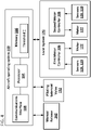
- FIG. 4 is a schematic diagram showing how the aircraft operating system 160 manages deployment and retraction of the main landing gears.
- the aircraft operating system 160 includes a processor 164 (e.g., a central processor, a distributed processor, etc.) electrically coupled to memory 166 and to one or more communications interfaces 168. Instructions for operating the aircraft systems (e.g., for managing the first and second motor controllers 106, 108) are stored in memory 166. In certain examples, a threshold pressure value or range T expected in high pressure lines within the power packs 110A, 110B also is stored in memory 166.
- the communications interfaces 168 electronically each electronically couple to one or more aircraft control systems.
- a communications interface 168 of the aircraft operating system 160 is electronically coupled to a local hydraulic control system 170.
- the local system 170 manages the first and second motor controllers 106, 108.
- separate communications interfaces 168 separately couple to the first and second motor controllers 106, 108.
- the first motor controller 106 operates the pump 120 (e.g., via the motor 122) of the first power pack 110A and the second motor controller 108 operates the pump 120 (e.g., via the motor 122) of the second power pack 110B.
- the aircraft operating system 160 also is electronically coupled (e.g., via the same or another communications interface 168) to the piloting solenoid valve 152.
- the operation system 160 is electronically coupled to the piloting solenoid valve 152 separate from the local hydraulic control system 170.
- the operation system 160 is electronically coupled to the piloting solenoid valve 152 through the local hydraulic control system 170.
- operation of the piloting solenoid valve 152 may be controlled directly by the local hydraulic control system 170.
- the aircraft operation system 160 also is separately electronically coupled to a manual release 162 for the main landing gear system.
- Each of the first and second motor controllers 106, 108 are electronically coupled to the motors 122 of the respective power packs 110A, 110B. Each of the first and second motor controllers 106, 108 are electronically coupled to the various sensors 128, 119 within the respective power pack 110A, 110B. Accordingly, the first and second motor controllers 106, 108 receive data (e.g., sensor data OSC) from the sensors 128, 119. Each motor controller 106, 108 also passes data to the aircraft operation system 160. In some examples, the motor controllers 106, 108 pass on the sensor data to the aircraft operation system 160. In other examples, the motor controllers 106, 108 process the sensor data to determine whether a fault has occurred in one of the power packs.
- data e.g., sensor data OSC
- Each motor controller 106, 108 also passes data to the aircraft operation system 160. In some examples, the motor controllers 106, 108 pass on the sensor data to the aircraft operation system 160. In other examples, the motor controllers 106, 108 process the
- the motor controller 106, 108 passes a fault alert to the aircraft operation system 160. In some implementations, the motor controller 106, 108 reporting the fault ceases operation. In other implementations, the motor controller 106, 108 reporting the fault continues trying to operate.
- the motor controller 106, 108 not reporting the fault continues normal operation (i.e., does not increase pump speed or otherwise vary the operation of the pump of the still functional power pack).
- the motor controller 106, 108 not reporting the fault may increase the pump speed to fill the demand.
- the corresponding pump 120 may be a variable speed pump configured to maintain a relatively constant hydraulic flow within a maximum speed limit.
- the aircraft operating system 160 Upon receiving the fault alert (or upon determining a fault condition based on the sensor readings), the aircraft operating system 160 is configured to trigger the piloting solenoid valve 152 to transition from the non-actuated position to the actuated position. Accordingly, the aircraft operating system 160 retains control over when to assign management of both main landing gears to a single power pack 110.
- the piloting solenoid valve 152 can be controlled by an independent electronic controller that monitors the sensor readings.
- the aircraft operating system 160 determines that the main landing gear should be deployed or retracted, the aircraft operating system 160 sends commands CS to the first motor controller 106 and the second motor controller 108 to run the motors 122 of both power packs 110A, 110B.
- Each of the first and second motor controllers 106, 108 runs the motor 122 of the respective power pack 110A, 110B to actuate the respective pump 120.
- each of the motor controller 106, 108 obtains sensor readings OSC (e.g., pressure readings from the pressure transducer 128) from the respective power pack 110A, 110B.
- OSC sensor readings
- the obtained sensor readings are analyzed (e.g., by the first and second motor controllers 106, 108) to determine whether or not the sensed pressure is below a predetermined threshold T.
- the threshold T is set based on the expected value of the pressure within the high pressure lines 121A, 121B when the power packs 110A, 110B are operating normally. If the pressure readings are below the threshold T, then the motor controller 106, 108 sensing the lack of pressure sends a fault alert back to the aircraft operating system 160.
- the aircraft operating system 160 activates the backup valve arrangement 140 to connect both main landing gear actuators 102, 104 to the power pack 110A, 110B that did not produce a fault. For example, the aircraft operating system 160 may send a command to the pilot solenoid 152 to transition to the actuated position.
- FIG. 5 illustrates the result of a failure in the first hydraulic power pack 110A of FIG. 1 .
- the failure occurs at the pump 120 or motor 122 of the first power pack 110A.
- the failure could occur at the high pressure filter module 124 or elsewhere along the high pressure line.
- the fluid in high pressure line 148B overwhelms the fluid in the high pressure line 148A so that the shuttle valve 154 outputs the fluid from the high pressure line 148B, which is fluidly coupled to the high pressure line 136B of the second power pack 110B. Accordingly, the fluid from the high pressure line 136B passes through the shuttle valve 154 to the piloting solenoid 152.
- the piloting solenoid 152 has been transitioned to the actuated position (e.g., electronically by the aircraft operating system 160) to allow the fluid from the shuttle valve 154 to press against the valve spool 150 to open the valve spool.
- the valve spool 150 couples the high pressure lines 146A, 146B to thereby couple the high pressure lines 136A, 136B from the first and second power packs 110A, 110B.
- the valve spool 150 also couples the low pressure lines 144A, 144B, which fluidly couple the low pressure lines 138A, 138B from the first and second power packs 110A, 110B.
- the pump 120 of the second power pack 110B pulls fluid from the combined low pressure line. Accordingly, the pump 120 of the second power pack 110B pulls fluid both from the reservoir 118 of the second power pack 110B and from the reservoir 118 of the first power pack 110A via the second return interface 116.
- the pump 120 drives the fluid through the high pressure filter module 124 and to the load interface 112 of the second power pack 110B. A portion of the fluid output through the load interface 112 of the second power pack 110B is routed to the right main landing gear 104. Another portion of the fluid output through the load interface 112 is routed through the valve spool 150 to the left main landing gear actuator 102. In particular, after passing through the valve spool 150, the fluid travels along the high pressure line 136A to the high pressure line 132A leading to the left main landing gear actuator 102.
- the fluid may pass through the low pressure filter module 126 and towards the reservoir 118 and/or pump 120.
- the fluid may pass through the low pressure filter module 126 and towards the second return interface 116 of the first power pack 110A.
- the fluid then exits the first power pack 110A through the respective second return interface 116, flows through the valve spool 150, and flows into the second power pack 110B through the respective second return interface 116 and towards the pump 120 or reservoir 118.
- no filter modules are disposed in either power pack 110A, 110B between the respective reservoir 118 and the respective second return interface 116.
- a hydraulic system to operate a main landing gear system on an aircraft including a left main landing gear actuator and a right main landing gear actuator, the hydraulic system comprising:
- Aspect 2 The hydraulic system of aspect 1, wherein the first and second load bypass interfaces are fluidly coupled to the respective load interfaces at locations external to the first and second hydraulic power packs.
- each of the first and second hydraulic power packs includes a respective low pressure filter element fluidly disposed between the respective first return interface and the respective reservoir; and wherein each of the first and second hydraulic power packs is devoid of filter elements between the respective second return interface and the respective reservoir.
- each hydraulic power pack includes a high pressure filter element disposed downstream of the respective pump and upstream of the respective load interface.
- Aspect 5 The hydraulic system of any of aspects 1-4, wherein the backup valve arrangement includes a valve spool movable between an open position and a closed position, the valve spool fluidly coupling the first load bypass interface and the second load bypass interface together when in the open position and decoupling the first and second load bypass interfaces when in the closed position, wherein the valve spool is biased to the closed position.
- Aspect 6 The hydraulic system of aspect 5, wherein the valve spool also fluidly couples the first and second tank bypass interfaces together when in the open position and decouples the first and second tank bypass interfaces when in the closed position.
- Aspect 7 The hydraulic system of aspect 5, wherein the backup valve arrangement also includes a shuttle valve to supply pressure to the valve spool to move the valve spool from the closed position to the open position, the shuttle valve having an output directed towards the valve spool, a first input fluidly coupled to the first load bypass interface, and a second input fluidly coupled to the second load bypass interface.
- Aspect 8 The hydraulic system of aspect 7, wherein the backup valve arrangement also includes a piloting solenoid disposed between the output of the shuttle valve and the valve spool, the piloting solenoid configured to selectively couple and decouple the output of the shuttle valve and the valve spool.
- Aspect 9 The hydraulic system of aspect 8, wherein the piloting solenoid valve is electronically controlled by a system processor for the aircraft.
- Aspect 10 The hydraulic system of any of aspects 1-9, wherein the first and second pumps are fixed displacement pumps driven by first and second variable speed motors, respectively.
- Aspect 11 The hydraulic fluid system of aspect 10, and preferably any of aspects 7-9 and 10, further comprising a first electronic controller configured to operate the first variable speed motor and a second electronic controller configured to operate the second variable speed motor, wherein neither the first electronic controller nor the second electronic controller is configured to operate the piloting solenoid valve.
- Aspect 12 The hydraulic fluid system of any of aspects 1-11, wherein the pump and reservoir of each hydraulic power pack are sized to supply sufficient power to operate the main landing gear actuator of one of the left and right main landing gears within a first time period and to supply sufficient power to operate the main landing gear actuators of both of the left and right main landing gears within a second time period that is longer than the first time period.
- a hydraulic system to operate a main landing gear system on an aircraft including a first main landing gear actuator and a second main landing gear actuator, each of the first and second main landing gear actuators operating a respective one of the left and right main landing gears, the hydraulic system comprising:
- Aspect 14 The hydraulic system of aspect 13, wherein the backup valve is biased to the closed position.
- Aspect 15 The hydraulic system of aspect 13, wherein the first and second low pressure fluid paths each include a low pressure filter element, and wherein the backup return path is devoid of any filter elements.
- Aspect 16 The hydraulic system of aspect 13, wherein the first and second high pressure fluid paths each include a high pressure filter element, and wherein the backup load path is devoid of any filter elements.
- Aspect 17 The hydraulic system of any of aspects 13-16, wherein the first and second pumps are electronically controlled by a local hydraulic controller arrangement electrically coupled to the electronic control system, and wherein a decision to actuate the piloting solenoid valve based on the received pressure data is made by a higher level system than the local hydraulic controller arrangement.
- Aspect 18 The hydraulic system of aspect 13, further comprising a shuttle valve supplying fluid to the piloting solenoid valve, the shuttle valve receiving the fluid from the backup load path.
Applications Claiming Priority (1)
| Application Number | Priority Date | Filing Date | Title |
|---|---|---|---|
| US202063119253P | 2020-11-30 | 2020-11-30 |
Publications (2)
| Publication Number | Publication Date |
|---|---|
| EP4006360A1 true EP4006360A1 (de) | 2022-06-01 |
| EP4006360B1 EP4006360B1 (de) | 2023-12-27 |
Family
ID=78806404
Family Applications (1)
| Application Number | Title | Priority Date | Filing Date |
|---|---|---|---|
| EP21210862.5A Active EP4006360B1 (de) | 2020-11-30 | 2021-11-26 | Redundante hydraulikaggregatarchitektur für das hauptfahrwerk eines flugzeugs |
Country Status (2)
| Country | Link |
|---|---|
| US (1) | US20220169367A1 (de) |
| EP (1) | EP4006360B1 (de) |
Citations (3)
| Publication number | Priority date | Publication date | Assignee | Title |
|---|---|---|---|---|
| GB973364A (en) * | 1961-10-11 | 1964-10-28 | Dowty Rotol Ltd | Fluid-pressure-operated-systems |
| US9422052B2 (en) * | 2012-12-04 | 2016-08-23 | Sumitomo Precision Products Co., Ltd. | Electro hydrostatic actuator system for retracting/extending landing gear |
| WO2017204698A1 (en) * | 2016-05-23 | 2017-11-30 | Volvo Construction Equipment Ab | Hydraulic system |
Family Cites Families (3)
| Publication number | Priority date | Publication date | Assignee | Title |
|---|---|---|---|---|
| US6513885B1 (en) * | 1999-05-14 | 2003-02-04 | Hydro-Aire, Inc. | Dual redundant active/active brake-by-wire architecture |
| DE10330805B4 (de) * | 2003-07-08 | 2015-07-30 | Liebherr-Aerospace Lindenberg Gmbh | Luftfahrzeug-Fahrwerksbetätigung |
| FR2966428B1 (fr) * | 2010-10-20 | 2013-08-02 | Messier Bugatti | Circuit hydraulique d'actionnement d'un atterrisseur et procedes de deploiement et de relevage d'un atterrisseur utilisant un tel circuit. |
-
2021
- 2021-11-26 EP EP21210862.5A patent/EP4006360B1/de active Active
- 2021-11-30 US US17/538,721 patent/US20220169367A1/en active Pending
Patent Citations (3)
| Publication number | Priority date | Publication date | Assignee | Title |
|---|---|---|---|---|
| GB973364A (en) * | 1961-10-11 | 1964-10-28 | Dowty Rotol Ltd | Fluid-pressure-operated-systems |
| US9422052B2 (en) * | 2012-12-04 | 2016-08-23 | Sumitomo Precision Products Co., Ltd. | Electro hydrostatic actuator system for retracting/extending landing gear |
| WO2017204698A1 (en) * | 2016-05-23 | 2017-11-30 | Volvo Construction Equipment Ab | Hydraulic system |
Also Published As
| Publication number | Publication date |
|---|---|
| EP4006360B1 (de) | 2023-12-27 |
| US20220169367A1 (en) | 2022-06-02 |
Similar Documents
| Publication | Publication Date | Title |
|---|---|---|
| EP2681366B1 (de) | Fehlererkennungs-, isolierungs- und rekonfigurationssystem für einen hydraulikkreis | |
| US9592905B2 (en) | Fuel intelligent crossfeed valve for detecting leakage in aircraft fuel tanks | |
| US11125254B2 (en) | Electro-hydraulic control system with fail-safe pilot valves | |
| JP3917587B2 (ja) | 油圧回路構造 | |
| US10882603B2 (en) | Distributed trailing edge wing flap systems | |
| CN100588592C (zh) | 用于操作飞机起落架的液压系统的系统 | |
| US20060226285A1 (en) | Local backup hydraulic actuator for aircraft control systems | |
| CA3025039C (en) | Distributed trailing edge wing flap systems | |
| JP3759732B2 (ja) | 操舵制御のための油圧システム装置 | |
| EP4006360A1 (de) | Redundante hydraulikaggregatarchitektur für das hauptfahrwerk eines flugzeugs | |
| US6769251B2 (en) | Hydraulic system architecture for controlling steering | |
| GB2586790A (en) | Aircraft hydraulic actuation system | |
| JPS6073102A (ja) | サ−ボシステムの制御方法及び装置 | |
| JP7228747B2 (ja) | 脚揚降用ehaシステム | |
| CA3098033A1 (en) | Electromechanical actuator pump | |
| CN112962710B (zh) | 挖掘机的液压系统、挖掘机及动力共享机群 | |
| CN116927280A (zh) | 一种液压控制系统及装载机 | |
| CN117345710A (zh) | 插销机构的液压控制系统和工程机械 | |
| CN117184393A (zh) | 一种具备失电应急功能的电液操舵装置及方法 |
Legal Events
| Date | Code | Title | Description |
|---|---|---|---|
| PUAI | Public reference made under article 153(3) epc to a published international application that has entered the european phase |
Free format text: ORIGINAL CODE: 0009012 |
|
| STAA | Information on the status of an ep patent application or granted ep patent |
Free format text: STATUS: THE APPLICATION HAS BEEN PUBLISHED |
|
| AK | Designated contracting states |
Kind code of ref document: A1 Designated state(s): AL AT BE BG CH CY CZ DE DK EE ES FI FR GB GR HR HU IE IS IT LI LT LU LV MC MK MT NL NO PL PT RO RS SE SI SK SM TR |
|
| STAA | Information on the status of an ep patent application or granted ep patent |
Free format text: STATUS: REQUEST FOR EXAMINATION WAS MADE |
|
| 17P | Request for examination filed |
Effective date: 20221124 |
|
| RBV | Designated contracting states (corrected) |
Designated state(s): AL AT BE BG CH CY CZ DE DK EE ES FI FR GB GR HR HU IE IS IT LI LT LU LV MC MK MT NL NO PL PT RO RS SE SI SK SM TR |
|
| P01 | Opt-out of the competence of the unified patent court (upc) registered |
Effective date: 20230521 |
|
| GRAP | Despatch of communication of intention to grant a patent |
Free format text: ORIGINAL CODE: EPIDOSNIGR1 |
|
| STAA | Information on the status of an ep patent application or granted ep patent |
Free format text: STATUS: GRANT OF PATENT IS INTENDED |
|
| INTG | Intention to grant announced |
Effective date: 20231013 |
|
| GRAS | Grant fee paid |
Free format text: ORIGINAL CODE: EPIDOSNIGR3 |
|
| GRAA | (expected) grant |
Free format text: ORIGINAL CODE: 0009210 |
|
| STAA | Information on the status of an ep patent application or granted ep patent |
Free format text: STATUS: THE PATENT HAS BEEN GRANTED |
|
| AK | Designated contracting states |
Kind code of ref document: B1 Designated state(s): AL AT BE BG CH CY CZ DE DK EE ES FI FR GB GR HR HU IE IS IT LI LT LU LV MC MK MT NL NO PL PT RO RS SE SI SK SM TR |
|
| REG | Reference to a national code |
Ref country code: GB Ref legal event code: FG4D |
|
| REG | Reference to a national code |
Ref country code: CH Ref legal event code: EP |
|
| REG | Reference to a national code |
Ref country code: DE Ref legal event code: R096 Ref document number: 602021008085 Country of ref document: DE |
|
| REG | Reference to a national code |
Ref country code: IE Ref legal event code: FG4D |
|
| PG25 | Lapsed in a contracting state [announced via postgrant information from national office to epo] |
Ref country code: GR Free format text: LAPSE BECAUSE OF FAILURE TO SUBMIT A TRANSLATION OF THE DESCRIPTION OR TO PAY THE FEE WITHIN THE PRESCRIBED TIME-LIMIT Effective date: 20240328 |
|
| REG | Reference to a national code |
Ref country code: LT Ref legal event code: MG9D |
|
| PG25 | Lapsed in a contracting state [announced via postgrant information from national office to epo] |
Ref country code: LT Free format text: LAPSE BECAUSE OF FAILURE TO SUBMIT A TRANSLATION OF THE DESCRIPTION OR TO PAY THE FEE WITHIN THE PRESCRIBED TIME-LIMIT Effective date: 20231227 |
|
| PG25 | Lapsed in a contracting state [announced via postgrant information from national office to epo] |
Ref country code: ES Free format text: LAPSE BECAUSE OF FAILURE TO SUBMIT A TRANSLATION OF THE DESCRIPTION OR TO PAY THE FEE WITHIN THE PRESCRIBED TIME-LIMIT Effective date: 20231227 |
|
| PG25 | Lapsed in a contracting state [announced via postgrant information from national office to epo] |
Ref country code: LT Free format text: LAPSE BECAUSE OF FAILURE TO SUBMIT A TRANSLATION OF THE DESCRIPTION OR TO PAY THE FEE WITHIN THE PRESCRIBED TIME-LIMIT Effective date: 20231227 Ref country code: GR Free format text: LAPSE BECAUSE OF FAILURE TO SUBMIT A TRANSLATION OF THE DESCRIPTION OR TO PAY THE FEE WITHIN THE PRESCRIBED TIME-LIMIT Effective date: 20240328 Ref country code: FI Free format text: LAPSE BECAUSE OF FAILURE TO SUBMIT A TRANSLATION OF THE DESCRIPTION OR TO PAY THE FEE WITHIN THE PRESCRIBED TIME-LIMIT Effective date: 20231227 Ref country code: ES Free format text: LAPSE BECAUSE OF FAILURE TO SUBMIT A TRANSLATION OF THE DESCRIPTION OR TO PAY THE FEE WITHIN THE PRESCRIBED TIME-LIMIT Effective date: 20231227 Ref country code: BG Free format text: LAPSE BECAUSE OF FAILURE TO SUBMIT A TRANSLATION OF THE DESCRIPTION OR TO PAY THE FEE WITHIN THE PRESCRIBED TIME-LIMIT Effective date: 20240327 |
|
| REG | Reference to a national code |
Ref country code: NL Ref legal event code: MP Effective date: 20231227 |