EP4006355A1 - Impeller for propeller fan, blower, and outdoor unit for air conditioner - Google Patents
Impeller for propeller fan, blower, and outdoor unit for air conditioner Download PDFInfo
- Publication number
- EP4006355A1 EP4006355A1 EP19939652.4A EP19939652A EP4006355A1 EP 4006355 A1 EP4006355 A1 EP 4006355A1 EP 19939652 A EP19939652 A EP 19939652A EP 4006355 A1 EP4006355 A1 EP 4006355A1
- Authority
- EP
- European Patent Office
- Prior art keywords
- upstream
- propeller fan
- impeller
- cylinder
- downstream
- Prior art date
- Legal status (The legal status is an assumption and is not a legal conclusion. Google has not performed a legal analysis and makes no representation as to the accuracy of the status listed.)
- Pending
Links
Images




Classifications
-
- F—MECHANICAL ENGINEERING; LIGHTING; HEATING; WEAPONS; BLASTING
- F04—POSITIVE - DISPLACEMENT MACHINES FOR LIQUIDS; PUMPS FOR LIQUIDS OR ELASTIC FLUIDS
- F04D—NON-POSITIVE-DISPLACEMENT PUMPS
- F04D29/00—Details, component parts, or accessories
- F04D29/26—Rotors specially for elastic fluids
- F04D29/32—Rotors specially for elastic fluids for axial flow pumps
- F04D29/325—Rotors specially for elastic fluids for axial flow pumps for axial flow fans
- F04D29/329—Details of the hub
-
- F—MECHANICAL ENGINEERING; LIGHTING; HEATING; WEAPONS; BLASTING
- F04—POSITIVE - DISPLACEMENT MACHINES FOR LIQUIDS; PUMPS FOR LIQUIDS OR ELASTIC FLUIDS
- F04D—NON-POSITIVE-DISPLACEMENT PUMPS
- F04D25/00—Pumping installations or systems
- F04D25/02—Units comprising pumps and their driving means
- F04D25/06—Units comprising pumps and their driving means the pump being electrically driven
-
- F—MECHANICAL ENGINEERING; LIGHTING; HEATING; WEAPONS; BLASTING
- F24—HEATING; RANGES; VENTILATING
- F24F—AIR-CONDITIONING; AIR-HUMIDIFICATION; VENTILATION; USE OF AIR CURRENTS FOR SCREENING
- F24F1/00—Room units for air-conditioning, e.g. separate or self-contained units or units receiving primary air from a central station
- F24F1/06—Separate outdoor units, e.g. outdoor unit to be linked to a separate room comprising a compressor and a heat exchanger
- F24F1/38—Fan details of outdoor units, e.g. bell-mouth shaped inlets or fan mountings
-
- F—MECHANICAL ENGINEERING; LIGHTING; HEATING; WEAPONS; BLASTING
- F05—INDEXING SCHEMES RELATING TO ENGINES OR PUMPS IN VARIOUS SUBCLASSES OF CLASSES F01-F04
- F05D—INDEXING SCHEME FOR ASPECTS RELATING TO NON-POSITIVE-DISPLACEMENT MACHINES OR ENGINES, GAS-TURBINES OR JET-PROPULSION PLANTS
- F05D2240/00—Components
- F05D2240/20—Rotors
- F05D2240/30—Characteristics of rotor blades, i.e. of any element transforming dynamic fluid energy to or from rotational energy and being attached to a rotor
- F05D2240/303—Characteristics of rotor blades, i.e. of any element transforming dynamic fluid energy to or from rotational energy and being attached to a rotor related to the leading edge of a rotor blade
-
- F—MECHANICAL ENGINEERING; LIGHTING; HEATING; WEAPONS; BLASTING
- F05—INDEXING SCHEMES RELATING TO ENGINES OR PUMPS IN VARIOUS SUBCLASSES OF CLASSES F01-F04
- F05D—INDEXING SCHEME FOR ASPECTS RELATING TO NON-POSITIVE-DISPLACEMENT MACHINES OR ENGINES, GAS-TURBINES OR JET-PROPULSION PLANTS
- F05D2250/00—Geometry
- F05D2250/70—Shape
- F05D2250/71—Shape curved
- F05D2250/712—Shape curved concave
-
- F—MECHANICAL ENGINEERING; LIGHTING; HEATING; WEAPONS; BLASTING
- F05—INDEXING SCHEMES RELATING TO ENGINES OR PUMPS IN VARIOUS SUBCLASSES OF CLASSES F01-F04
- F05D—INDEXING SCHEME FOR ASPECTS RELATING TO NON-POSITIVE-DISPLACEMENT MACHINES OR ENGINES, GAS-TURBINES OR JET-PROPULSION PLANTS
- F05D2270/00—Control
- F05D2270/01—Purpose of the control system
- F05D2270/11—Purpose of the control system to prolong engine life
- F05D2270/114—Purpose of the control system to prolong engine life by limiting mechanical stresses
Definitions
- Embodiments of the present invention relate to an impeller for a propeller fan, a blower, and an outdoor unit for an air conditioner.
- a propeller fan is used as a blower for an outdoor unit of an air conditioner.
- the propeller fan includes an impeller, and an electric motor that generates the rotational driving force of the impeller.
- the impeller includes a tubular boss, and a plurality of blades that radially protrude from the outer peripheral surface of the boss.
- the boss includes: a shaft mounting portion provided with a rotating shaft that connects the electric motor and the propeller fan; a plurality of ribs that radially extend from the outer peripheral surface of the shaft mounting portion to the inner wall of the boss; a downstream-side bridging wall that connects between the plurality of ribs; and an upstream-side bridging wall that connects between the plurality of ribs on the upstream side of the downstream-side bridging wall.
- the downstream-side bridging wall and the upstream-side bridging wall do not overlap in the direction along the rotation centerline of the propeller fan.
- the upstream-side bridging wall is provided on the rotation centerline side of the base end portion of the leading edge of each blade.
- the largest load is generated in the connection portion between the boss and the root portion of the leading edge of each blade.
- the conventional propeller fan still has room for improving stress concentration in the connection portion between the boss and the root portion of the leading edge of each blade.
- An object of the present invention is to provide an impeller, which is for a propeller fan, that can more effectively relieve stress concentration in the connection portion between the root portion of the leading edge of each blade and the boss.
- an aspect of the present invention provides an impeller for a propeller fan including: a boss; and a plurality of blades that radially protrude from an outer peripheral surface of the boss.
- the boss includes: a cylinder that has the outer peripheral surface and extends from an upstream-side end to a downstream-side end; a plurality of upstream-side bridging walls, each of which has a surface facing a direction along a centerline of the cylinder and a connection portion continuous with the upstream-side end, and extends to inside of the cylinder; and a plurality of downstream-side bridging walls, each of which has a surface facing a direction along the centerline of the cylinder, that is closer to the downstream-side end than the upstream-side bridging walls, and extends to inside of the cylinder.
- a root portion of a leading edge of each of the plurality of blades is continuous with the upstream-side end.
- an aspect of the present invention provides a blower including: the propeller fan; and an electric motor that drives the propeller fan.
- an aspect of the present invention provides an outdoor unit for an air conditioner including: the blower; and a heat exchanger configured to exchange heat with air flowed by the blower.
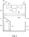
- Fig. 1 is a cross-sectional view of an outdoor unit for an air conditioner according to one embodiment of the present invention.
- the air conditioner includes an outdoor unit 100, and an indoor unit (not shown).
- the outdoor unit 100 includes: a housing 101; a blower 103 having an electric motor 102; a heat exchanger 105; a compressor 106; a four-way valve (not shown); and a controller (not shown) .
- the blower 103, the heat exchanger 105, the compressor 106, the four-way valve, and the controller are arranged inside the housing 101.
- the housing 101 includes: a side plate 111 that covers the side face, a top plate 112 that covers the ceiling; and a bottom plate 113 that covers the bottom face.
- a partition plate 115 is provided inside the housing 101. The partition plate 115 partitions the inside of the housing 101 into a machine chamber 117 and a heat exchange chamber 118.
- the side plate 111 has a plurality of inlet holes 111a that suck outside air into the outdoor unit 100.
- an outlet hole 112a and a bell mouth are provided at the central portion of the top plate 112.
- the outlet hole 112a exhausts the outside air, which has been sucked into the outdoor unit 100 from the inlet holes 111a of the side plate 111, to the outside of the outdoor unit 100.
- the compressor 106 is installed on the bottom plate 113 of the machine room 117 and is located below the heat exchanger 105.
- the heat exchanger 105 is installed in the central portion of the heat exchange chamber 118.
- the blower 103 is located above the heat exchanger 105 and is installed near the outlet hole 112a of the top plate 112.
- the outdoor unit 100 is connected to the indoor unit via a refrigerant pipe (not shown).
- a refrigerant pipe (not shown).
- the compressor 106 When the refrigeration cycle operation is started, the compressor 106 is driven.
- the compressor 106 circulates the refrigerant through the refrigerant pipe and leads it to the heat exchanger 105.
- the operation of the blower 103 is started.
- the electric motor 102 drives a propeller fan 1 to rotate.
- the outside air is led to the heat exchange chamber 118 from the inlet holes 111a on the side face of the housing 101, passes through the heat exchanger 105, and exchanges heat with the refrigerant in the heat exchanger 105.
- the air having been heat-exchanged with the heat exchanger 105 is led to the bell mouth via the blower 103 and is discharged to the outside of the outdoor unit 100 from the outlet hole 112a at the upper portion of the housing 101.
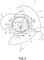
- Fig. 2 is a perspective view of an impeller for a propeller fan according to the embodiment of the present invention as viewed from the upstream side of the airflow.
- Fig. 3 is a perspective view of the impeller for the propeller fan according to the embodiment of the present invention as viewed from the downstream side of the airflow.
- the propeller fan 1 As shown in Fig. 2 and Fig. 3 , the propeller fan 1 according to the present embodiment rotates in the rotation direction R indicated by the solid arrow in Fig. 2 and Fig. 3 so as to cause the fluid, exclusively air, to flow in the flow direction F indicated by the solid arrow in Fig. 2 and Fig. 3 .
- the propeller fan 1 When the propeller fan 1 is rotated in the direction opposite to the rotation direction R, the fluid flows in the direction opposite to the flow direction F.
- the propeller fan 1 is applied to, for example, an outdoor unit for an air conditioner, and is used for blowing air to an outdoor heat exchanger.
- the propeller fan 1 is a so-called axial-flow fan.
- the propeller fan 1 includes an impeller 2, and an electric motor (not shown) for rotating and driving the impeller 2.
- the electric motor includes an output shaft (not shown) that transmits rotational driving force to the impeller 2.
- the output shaft is the rotation center of the impeller 2.
- Fig. 4 is a longitudinal cross-sectional view of the impeller for the propeller fan according to the embodiment of the present invention.
- the impeller 2 for the propeller fan 1 is a so-called axial-flow impeller.
- the impeller 2 is also simply called a propeller.
- the impeller 2 includes a boss 5 and a plurality of blades 6 that radially protrude from an outer peripheral surface 5a of the boss 5.
- the impeller 2 is integrally molded with, for example, resin.
- the plurality of blades 6 are arranged at equal intervals along the outer peripheral surface 5a of the boss 5 in the circumferential direction of the impeller 2, i.e., in the rotation direction R of the propeller fan 1.
- the impeller 2 has, for example, three blades 6. In this case, the three blades 6 are arranged at every 120° as the central angle.
- the respective blades 6 are tilted toward the upstream side in the rotation direction of the propeller fan 1, and are arranged on the outer peripheral surface 5a of the boss 5.
- the root portion 31a of the leading edge 31 of each blade 6 coincides with the upstream-side end 11s of the boss 5.
- the boss 5 includes: a cylinder 11 that has the outer peripheral surface 5a of the boss 5 and extends from the upstream-side end 11s to the downstream-side end 11b; a plurality of upstream-side bridging walls 12, each of which has a upstream-side end face 12a facing the direction along the centerline of the cylinder 11 and a connection portion 12b continuous with the upstream-side end 11s of the boss 5, and extend to the center of the cylinder 11; a plurality of downstream-side bridging walls 13, each of which has a downstream-side end face 13a facing the direction along the centerline of the cylinder 11 and is closer to the downstream-side end 11b than the upstream-side bridging walls, and extend to the center of the cylinder 11; and a rotating-shaft mounting portion 15 that is disposed in the center of the cylinder 11 via the plurality of upstream-side bridging walls 12 and the plurality of downstream-side bridging walls 13.
- the rotating-shaft mounting portion 15 is disposed on the rotation centerline of the boss 5 and on the rotation centerline of the impeller 2.
- the rotating shaft is fixed to the rotating-shaft mounting portion 15.
- the impeller 2 is connected to the electric motor via the rotating-shaft mounting portion 15 that is fixed to the rotating shaft.
- the rotating-shaft mounting portion 15 may be one that fixes the inserted rotating shaft or may be one that is integrated with the rotating shaft by insert molding.
- the plurality of upstream-side bridging walls 12 are a flat plate portion that has substantially uniform-thickness, and extends from the upstream-side end 11s of the cylinder 11 toward the center of the cylinder 11.
- Each upstream-side bridging wall 12 has: a front end 16 located forward in the rotation direction R of the propeller fan 1; and a rear end 17 located behind the front end 16. The outer edge of each upstream-side bridging wall 12 is continuously connected to the upstream-side end 11s of the cylinder 11.
- the plurality of downstream-side bridging walls 13 are a flat plate portion that has substantially uniform-thickness, and extends from the downstream-side end 11b of the cylinder 11 toward the center of the cylinder 11.
- Each downstream-side bridging wall 13 has: a front end 18 located forward in the rotation direction R of the propeller fan 1; and a rear end 19 located behind the front end 18.
- the outer edge of each downstream-side bridging wall 13 is continuous with the downstream-side end 11b of the cylinder 11.
- the outer edge of each downstream-side bridging wall 13 may be located inside the cylinder 11 and may not be continuous with the downstream-side end 11b.
- the plurality of upstream-side bridging walls 12 and the plurality of downstream-side bridging walls 13 are alternately arranged in the rotation direction R of the propeller fan 1.
- the plurality of upstream-side bridging walls 12 and the plurality of downstream-side bridging walls 13 do not overlap in the direction along the rotation centerline of the propeller fan 1.
- the number of upstream-side bridging walls 12, the number of downstream-side bridging walls 13, and the number of blades 6 are the same.
- the upstream-side bridging walls 12, downstream-side bridging walls 13, and blades 6 are regularly arranged around the rotation center of the propeller fan 1.
- a longitudinal wall 21 extending in the direction of the rotation centerline of the propeller fan 1 is provided.
- the longitudinal wall 21 has a substantially uniform thickness.
- a plurality of longitudinal walls 21 are provided. Each of half of the longitudinal walls 21 includes the rear end 17 of each upstream-side bridging wall 12 and the front end 18 of each downstream-side bridging wall 13, while each of the other half of the longitudinal walls 21 includes the front end 16 of each upstream-side bridging wall 12 and the rear end 19 of each downstream-side bridging wall 13.
- Each longitudinal wall 21 is bridged between the inner peripheral surface 11a of the cylinder 11 and the rotating-shaft mounting portion 15.
- the plurality of longitudinal walls 21 radially extends from the rotating-shaft mounting portion 15 to the cylinder 11.
- the upstream-side bridging walls 12 extend in a fan shape from the rotating-shaft mounting portion 15 toward the upstream-side end 11s of the cylinder 11 over the upstream-side ends 21s of the adjacent longitudinal walls 21, the upstream-side end 11s of the cylinder 11, and the upstream-side end 15s of the rotating-shaft mounting portion 15.
- the rotating-shaft mounting portion 15 corresponds to the pivot of the fan-shaped upstream-side bridging walls 12.
- the downstream-side bridging walls 13 extend in a fan shape from the downstream-side end 15b of the rotating-shaft mounting portion 15 toward the downstream-side bridging wall of the cylinder 11 over the downstream-side ends 21b of the adjacent longitudinal walls 21, the downstream-side end 11b of the cylinder 11, and the downstream-side end 15b of the rotating-shaft mounting portion 15.
- the rotating-shaft mounting portion 15 corresponds to the pivot of the fan-shaped downstream-side bridging walls 13. That is, the plurality of upstream-side bridging walls 12 and the plurality of downstream-side bridging walls 13 are alternately and radially arranged around the rotating-shaft mounting portion 15.
- each upstream-side bridging wall 12 is located behind the root portion 31a of the leading edge 31 of the nearest blade 6 in the rotation direction of the propeller fan 1.
- the rear end 17 of each upstream-side bridging wall 12 is located behind the root portion 31a of the leading edge 31 of the nearest blade 6.
- the front end 16 of the connection portion 12b of each upstream-side bridging wall 12 may coincide with the root portion 31a of the leading edge 31 of the nearest blade 6 in the rotation direction of the propeller fan 1, may be located behind the root portion 31a of the leading edge 31 of the nearest blade 6, or may be located in front of the root portion 31a of the leading edge 31 of the nearest blade 6.
- the front end 16 of each upstream-side bridging wall 12 is located in front of the root portion 31a of the leading edge 31 of the nearest blade 6.
- the root portion 31a of the leading edge 31 of each blade 6 is preferably sandwiched between the front end 16 and the rear end 17 of the connection portion 12b of the upstream-side bridging wall 12.
- the front end 16 and the rear end 17 of each upstream-side bridging wall 12 preferably sandwich the root portion 31a of the leading edge 31 of the blade 6.
- the root portion 31a of the leading edge 31 of each blade 6 is continuous with the upstream-side end 11s of the cylinder 11.
- the root portion 31a of the leading edge 31 of each blade 6 and the outermost edge of each upstream-side bridging wall 12 face each other with the upstream-side end 11s of the cylinder 11 interposed therebetween, without offsetting in the rotation direction of the propeller fan 1.
- the impeller 2 includes: the root portion 31a of the leading edge 31 of each blade 6 that is continuous with the upstream-side end 11s of the cylinder 11; and the upstream-side bridging walls 12 that are continuous with the upstream-side end 11s of the cylinder 11. Consequently, the impeller 2 distributes the load to be generated in the root portion 31a of the leading edge 31 of each blade 6 to the upstream-side bridging walls 12, the longitudinal walls 21, and the cylinder 11 of the boss 5 so as to relieve stress concentration in the root portion 31a of the leading edge 31 of each blade 6.
- the upstream-side end 11s of cylinder 11 is not located between the root portion 31a of the leading edge 31 of each blade 6 and the outermost edge of each upstream-side bridging wall 12, and the upstream-side end 11s of cylinder 11 protrudes toward the upstream-side of the propeller fan 1 to be away from the portion sandwiched between the root portion 31a of the leading edge 31 of each blade 6 and the outermost edge of each upstream-side bridging wall 12, the proportion of the load to be distributed with the upstream-side bridging walls 12 is reduced. That is, the improvement of the stress concentration in the root portion 31a of the leading edge 31 of each blade 6 remains insufficient.
- the proportion of the load to be distributed with the upstream-side bridging walls 12 is reduced.
- the proportion of the load to be distributed with the upstream-side bridging walls 12 is reduced. That is, the improvement of the stress concentration in the root portion 31a of the leading edge 31 of each blade 6 remains insufficient.
- the upstream-side bridging walls 12 bears the load to be generated in the root portion 31a of the leading edge 31 of each blade 6 as intended so as to relieve the stress concentration in the root portion 31a of the leading edge 31 of each blade 6.
- the reason for such improvement is considered to be that the upstream-side bridging wall 12 in the rear side bears the load to be generated in the root portion 31a located forward via the cylinder 11 in the rotation direction R of the propeller fan 1.
- each upstream-side bridging wall 12 is located behind the root portion 31a of the leading edge 31 of the nearest blade 6 in the rotation direction R of the propeller fan 1. Consequently, the impeller 2 distributes the load to be generated in the root portion 31a of the leading edge 31 of each blade 6 to the upstream-side bridging walls 12 and the cylinder 11 of the boss 5 so as to relieve the stress concentration in the root portion 31a of the leading edge 31 of each blade 6.
- the impeller 2 includes the root portion 31a of the leading edge 31 of each blade 6, and this root portion 31a is sandwiched between the front end 16 and the rear end 17 of the upstream-side bridging wall 12. Consequently, the impeller 2 distributes the load to be generated in the root portion 31a of the leading edge 31 of each blade 6 to the upstream-side bridging walls 12 and the cylinder 11 of the boss 5, and thus the impeller 2 more effectively relieves the stress concentration in the root portion 31a of the leading edge 31 of each blade 6.
- the impeller 2 includes: the upstream-side bridging walls 12; and the downstream-side bridging walls 13, both of which do not overlap in the direction along the rotation centerline of the propeller fan 1. Consequently, the impeller 2 can be readily integrally molded by the mold that can be divided in the direction of the rotation centerline.
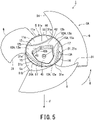
- Fig. 5 is a perspective view of the second aspect of the impeller for the propeller fan according to the embodiment of the present invention as viewed from the upstream side.
- Fig. 6 is a perspective view of the second aspect of the impeller for the propeller fan according to the embodiment of the present invention as viewed from the downstream side
- Fig. 7 is a longitudinal cross-sectional view of the second aspect of the impeller for the propeller fan according to the embodiment of the present invention.
- the impeller 2A of the second aspect for the propeller fan 1 includes a plurality of upstream-side bridging walls 12A that have annularly continuous connection portions 12b located away from the inner peripheral surface 11a of cylinder 11, and are integrated with an annular portion 41.
- the impeller 2A of the second aspect for the propeller fan 1 is simply referred to as "the impeller 2A".
- Each upstream-side bridging wall 12A is a plate portion that has a substantially uniform thickness, and is curved in a concave shape from the upstream-side end 11s of the cylinder 11 toward the downstream side.
- the concave bottom, i.e., the portion of each upstream-side bridging wall 12A farthest from the upstream-side end 11s of the cylinder 11 is closest to the center of the propeller fan 1.
- the annular portion 41 integrates the plurality of upstream-side bridging walls 12A.
- the annular portion 41 is a part of the upstream-side bridging walls 12A, and is curved in a concave shape from the upstream-side end 11s of the cylinder 11 toward the downstream side.
- the portions of the plurality of upstream-side bridging walls 12A near the cylinder 11 are connected to the cylinder 11 for each blade 6, whereas the portions of the plurality of upstream-side bridging walls 12A far from the cylinder 11, that is, the portions of the plurality of upstream-side bridging walls 12A near the rotating-shaft mounting portion 15A are connected in succession by the annular portion 41. That is, the plurality of upstream-side bridging walls 12A are radially arranged from the annular portion 41 disposed inside the cylinder 11 toward the inner peripheral surface 11a of the cylinder 11.
- the front end 16 of the connection portion 12b of one upstream-side bridging wall 12A is continuous with the rear end 17 of the connection portion 12b of the upstream-side bridging wall 12A located forward in the rotation direction of the propeller fan 1.
- the front end 16 and the rear end 17 of the adjacent upstream-side bridging walls 12A are connected in succession.
- These continuous front end 16 and rear end 17 of the upstream-side bridging walls 12A have a rectilinear shape when viewed in the direction of the rotation centerline of the propeller fan 1, and have an arc shape concavely recessed from the upstream-side end 11s of the cylinder 11 toward the downstream side.
- the longitudinal wall 21A extends in a flat plate shape in the direction of the rotation centerline of the propeller fan 1 connecting these continuous front end 16 and rear end 17.
- the portion of the cylinder 11 facing the longitudinal wall 21A may be notched as long as it does not interfere with the support of the blades 6. The notch contributes to the weight reduction of the propeller fan 1.
- the downstream-side bridging walls 13A are provided in the portions surrounded by the upstream-side bridging walls 12A and the cylinder 11 when viewed in the direction of the rotation centerline of the propeller fan 1.
- An annular longitudinal wall 42 is provided on the inner edge of the annular portion 41.
- the annular longitudinal wall 42 extends from the inner edge of the annular portion 41 toward the downstream-side end 11b of the cylinder 11.
- the annular longitudinal wall 42 may or may not reach the downstream-side end 11b of the cylinder 11.
- the downstream-side end 42b of the annular longitudinal wall 42 is connected to the rotating-shaft mounting portion 15A.
- the inner edge shape of the annular portion 41 may be a simple circular shape or a polygonal shape as shown in Fig. 5 when viewed in the direction of the rotation centerline of the propeller fan 1.
- the inner edge shape of the polygon includes: a vertex on a line segment bisecting the connection portion, which is between the upstream-side bridging walls 12A and the cylinder 11, in the rotation direction of the propeller fan 1; and another vertex on a line segment bisecting the arc-shaped portion, which separates the upstream-side bridging walls 12A from the cylinder 11, in the rotation direction of the propeller fan 1.
- the inner edge shape of the annular portion 41 forms a hexagon.
- the rotating-shaft mounting portion 15A has a flange 45 that is closer to the downstream-side end 11b of the cylinder 11 than the annular portion 41 shared by the plurality of upstream-side bridging walls 12A.
- the flange 45 is a wall that extends in the direction perpendicular to the rotation center of the propeller fan 1 and is connected to the downstream-side end 42b of the annular longitudinal wall 42.
- the flange 45 is a wall that closes the inner boundary of the annular portion 41.
- the impeller 2A includes: the root portion 31a of the leading edge 31 of each blade 6 that is continuous with the upstream-side end 11s of the cylinder 11; and the upstream-side bridging walls 12A continuous with the upstream-side end 11s of the cylinder 11. Consequently, the impeller 2A distributes the load to be generated in the root portion 31a of the leading edge 31 of each blade 6 to the upstream-side bridging walls 12A and the cylinder 11 of the boss 5 so as to relieves the stress concentration in the root portion 31a of the leading edge 31 of each blade 6.
- each upstream-side bridging wall 12A is located behind the root portion 31a of the leading edge 31 of the nearest blade 6 in the rotation direction R of the propeller fan 1. Consequently, the impeller 2A distributes the load to be generated in the root portion 31a of the leading edge 31 of each blade 6 to the upstream-side bridging walls 12A and the cylinder 11 of the boss 5 so as to relieve the stress concentration in the root portion 31a of the leading edge 31 of each blade 6.
- the impeller 2A includes the root portion 31a of the leading edge 31 of each blade 6, and the root portion 31a is sandwiched between the front end 16 and the rear end 17 of the upstream-side bridging wall 12A. Consequently, the impeller 2A distributes the load to be generated in the root portion 31a of the leading edge 31 of each blade 6 to the upstream-side bridging walls 12A and the cylinder 11 of the boss 5, and thus the impeller 2A more effectively relieves the stress concentration in the root portion 31a of the leading edge 31 of each blade 6.
- the impeller 2A includes: the upstream-side bridging walls 12; and the downstream-side bridging walls 13, both of which do not overlap in the direction along the rotation centerline of the propeller fan 1. Consequently, the impeller 2A can be readily integrally molded by the mold that can be divided in the direction of the rotation centerline.
- the impeller 2A includes the plurality of upstream-side bridging walls 12A integrated with the annularly continuous annular portion 41 that is located away from the inner peripheral surface 11a of the cylinder 11. Consequently, the impeller 2A distributes the stress to be generated in the root portion 31a of the leading edge 31 of each blade 6 to the upstream-side bridging walls 12A and the cylinder 11 of the boss 5 and also causes the annular portion 41 to bear the stress dispersed by the upstream-side bridging walls 12A, and thus the impeller 2A further relieves the stress concentration in the root portion 31a of the leading edge 31 of each blade 6.
- Fig. 8 is a view of the boss of the second aspect of the impeller for the propeller fan according to the embodiment of the present invention as viewed from the upstream-side.
- the impeller 2A for the propeller fan 1 may be provided with drain holes 47, opening width of each of which decreases from the center side to the outer peripheral side of the boss 5, in the upstream-side bridging walls 12A.
- the drain holes 47 are provided on the outer peripheral portions of the respective upstream-side bridging walls 12A.
- Each drain hole 47 has an oval shape extending toward the center side of the boss 5 or toward the inner peripheral side of the upstream-side bridging wall 12A.
- Each drain hole 47 has: a first semi-arc-shaped portion 47a that is provided on the inner peripheral side, and is convex toward the center side of boss 5 or toward the inner peripheral side of the upstream-side bridging wall 12A; and a wedge-shaped portion 47b that is continuous with the chord portion of the first semi-circular arc-shaped portion 47a, and has opening width decreasing at a substantially constant rate from the center side to the outer peripheral side of the boss 5.
- Each drain hole 47 has a shape that is line-symmetric with respect to an imaginary line extending in the radial direction of the propeller fan 1.
- the minimum opening width portion of the wedge-shaped portion 47b i.e., the portion closest to the outer edge of the boss 5, is closed in a trapezoidal shape along the outer edge of the boss 5.
- each drain hole 47 is configured as described above, the impeller 2A can increase the area of the drain holes 47 and appropriately drain moisture such as rainwater to be accumulated in the boss 5 while relieving the stress concentration in the root portion 31a of the leading edge 31 of each blade 6. Since the drain holes 47 are provided in the upstream-side bridging walls 12A that widely spread in the vicinity of the root portions 31a, each drain hole 47 has a degree of freedom to secure a large opening area and can readily drain even water in a solid state, such as a factor of ice or hail. In addition, each drain hole 47 has an egg shape that extends toward the center of the boss 5.
- the water to be accumulated on the downstream side of the propeller fan 1 is readily drained from the propeller fan 1 along the inclination of the upstream-side bridging walls 12A.
- the moisture is also readily drained as it travels outwards of the rotating propeller fan 1.
- Fig. 9 is a perspective view of the third aspect of the impeller for the propeller fan according to the embodiment of the present invention as viewed from the upstream-side.
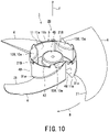
- Fig. 10 is a perspective view of the third aspect of the impeller for the propeller fan according to the embodiment of the present invention as viewed from the downstream side.
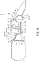
- Fig. 11 is a longitudinal cross-sectional view of the third aspect of the impeller for the propeller fan according to the embodiment of the present invention.
- the impeller 2B of the third aspect for the propeller fan 1 includes a plurality of upstream-side bridging walls 12B that have annularly continuous connection portions 12b located away from the inner peripheral surface 11a of the cylinder 11, and are integrated with an annular portion 41B.
- the impeller 2B of the third aspect for the propeller fan 1 is simply referred to as "the impeller 2B".
- Each upstream-side bridging wall 12B is a plate portion that has a substantially uniform thickness and is curved in a concave shape from the upstream-side end 11s of the cylinder 11 toward the downstream side.
- the concave bottom i.e., the portion of each upstream-side bridging wall 12B farthest from the upstream-side end 11s of the cylinder 11, is closest to the center of the propeller fan 1.
- the annular portion 41B integrates the plurality of upstream-side bridging walls 12B.
- the annular portion 41B is a part of the upstream-side bridging walls 12B, and extends from the upstream-side end 11s of the cylinder 11 toward the center of the cylinder 11.
- the portions of the respective portions of the plurality of upstream-side bridging walls 12B near the cylinder 11 are connected to the cylinder 11 for each blade 6, whereas the portions of the plurality of upstream-side bridging walls 12B far from the cylinder 11, that is, the portions of the plurality of upstream-side bridging walls 12B near the rotating-shaft mounting portion 15B, are connected in succession by the annular portion 41B. That is, the plurality of upstream-side bridging walls 12B are radially arranged from the annular portion 41B disposed inside the cylinder 11 toward the inner peripheral surface 11a of the cylinder 11.
- the front end 16 of the connection portion 12b of one upstream-side bridging wall 12B is continuous with the rear end 17 of the connection portion 12b of the upstream-side bridging wall 12B located forward in the rotation direction of the propeller fan 1.
- the front end 16 and the rear end 17 of the adjacent upstream-side bridging walls 12B are connected in succession.
- These continuous front end 16 and rear end 17 of the upstream-side bridging walls 12B have a curved shape, for example, an arc shape having a center of curvature on the outside of the cylinder 11, i.e., on the side of the blades 6, when viewed in the direction of the rotation centerline of the propeller fan 1.
- these continuous front end 16 and rear end 17 of the upstream-side bridging walls 12B have an arc shape that is concavely recessed toward the inside of the boss 5. Further, the continuous front end 16 and rear end 17 of the upstream-side bridging walls 12B have an arc shape that is concavely recessed from the upstream-side end 11s of the cylinder 11 toward the downstream side. These continuous front end 16 and rear end 17 are connected to the downstream-side bridging walls 13B via the longitudinal wall 21B. Each longitudinal wall 21B is curved in a concavely recessed arc shape toward the inside of the boss 5 following these continuous front end 16 and rear end 17, and extends with a substantially uniform thickness. As shown in Fig. 10 , of the cylinder 11, the portion facing the longitudinal wall 21B has a notch as long as it does not interfere with the support of the blades 6.
- the downstream-side bridging walls 13B are provided in the portions surrounded by the upstream-side bridging walls 12B and the cylinder 11 when viewed in the direction of the rotation centerline of the propeller fan 1.
- the annular longitudinal wall 42 is provided on the inner edge of the annular portion 41B.
- the annular longitudinal wall 42 extends from the inner edge of the annular portion 41 toward the downstream-side end 11b of the cylinder 11.
- the annular longitudinal wall 42 may or may not reach the downstream-side end 11b of the cylinder 11.
- the downstream-side end 42b of the annular longitudinal wall 42 is connected to the rotating-shaft mounting portion 15B.
- the inner edge shape of the annular portion 41B may be a simple circular shape as shown in Fig. 9 or a polygonal shape when viewed in the direction of the rotation centerline of the propeller fan 1.
- the inner edge shape of the polygonal shape includes: a vertex on a line segment bisecting the connection portion, which is between the upstream-side bridging walls 12B and the cylinder 11, in the rotation direction of the propeller fan 1; and another vertex on a line segment bisecting the arc-shaped portion, which separates the upstream-side bridging walls 12B from the cylinder 11, in the rotation direction of the propeller fan 1.
- the rotating-shaft mounting portion 15B has a flange 45 that is closer to the downstream-side end 11b of the cylinder 11 than the annular portion 41B shared by the plurality of upstream-side bridging walls 12B.
- the flange 45 is a wall that extends in the direction perpendicular to the rotation center of the propeller fan 1 and is connected to the downstream-side end 42b of the annular longitudinal wall 42.
- the flange 45 is a wall that closes the inner boundary of the annular portion 41.
- the impeller 2B includes: the root portion 31a of the leading edge 31 of each blade 6 that is continuous with the upstream-side end 11s of the cylinder 11; and the upstream-side bridging walls 12B that are continuous with the upstream-side end 11s of the cylinder 11. Consequently, the impeller 2B distributes the load to be generated in the root portion 31a of the leading edge 31 of each blade 6 to the upstream-side bridging walls 12B and the cylinder 11 of the boss 5 so as to relieve the stress concentration in the root portion 31a of the leading edge 31 of each blade 6.
- each upstream-side bridging wall 12B is located behind the root portion 31a of the leading edge 31 of the nearest blade 6 in the rotation direction R of the propeller fan 1. Consequently, the impeller 2B distributes the load to be generated in the root portion 31a of the leading edge 31 of each blade 6 to the upstream-side bridging walls 12B and the cylinder 11 of the boss 5 so as to relieve the stress concentration in the root portion 31a of the leading edge 31 of each blade 6.
- the impeller 2B includes the root portion 31a of the leading edge 31 of each blade 6, and this the root portion 31a is sandwiched between the front end 16 and the rear end 17 of the upstream-side bridging wall 12B. Consequently, the impeller 2B distributes the load to be generated in the root portion 31a of the leading edge 31 of each blade 6 to the upstream-side bridging walls 12B and the cylinder 11 of the boss 5, and thus the impeller 2B more effectively relieves the stress concentration in the root portion 31a of the leading edge 31 of each blade 6.
- the impeller 2B includes: the upstream-side bridging walls 12B; and the downstream-side bridging walls 13B, both of which do not overlap in the direction along the rotation centerline of the propeller fan 1. Consequently, the impeller 2B can be readily integrally molded by the mold that can be divided in the direction of the rotation centerline.
- the impeller 2B includes the plurality of upstream-side bridging walls 12B integrated with the annularly continuous annular portion 41B that is located away from the inner peripheral surface 11a of cylinder 11. Consequently, the impeller 2B distributes the stress to be generated in the root portion 31a of the leading edge 31 of each blade 6 to the upstream-side bridging walls 12B and the cylinder 11 of the boss 5 and also causes the annular portion 41 to bear the stress to be dispersed by the upstream-side bridging walls 12B, and thus the impeller 2B further relieves the stress concentration in the root portion 31a of the leading edge 31 of each blade 6.
- the impeller 2B includes the front end 16 and the rear end 17 of the adjacent upstream-side bridging walls 12B that have an arc shape concavely recessed toward the inside of the boss 5. Consequently, the impeller 2B increases the stress to be borne by the upstream-side bridging walls 12B and the annular portion 41B, and thus the impeller 2B more significantly relieves the stress concentration in the root portion 31a of the leading edge 31 of each blade 6.
- the impellers 2, 2A, and 2B for the propeller fan 1 according to the present embodiment can more effectively relieve the stress concentration in the connection portion between the boss 5 and the root portion 31a of the leading edge 31 of each blade 6.
Landscapes
- Engineering & Computer Science (AREA)
- Mechanical Engineering (AREA)
- General Engineering & Computer Science (AREA)
- Chemical & Material Sciences (AREA)
- Combustion & Propulsion (AREA)
- Structures Of Non-Positive Displacement Pumps (AREA)
- Other Air-Conditioning Systems (AREA)
Abstract
Description
- Embodiments of the present invention relate to an impeller for a propeller fan, a blower, and an outdoor unit for an air conditioner.
- A propeller fan is used as a blower for an outdoor unit of an air conditioner. The propeller fan includes an impeller, and an electric motor that generates the rotational driving force of the impeller. The impeller includes a tubular boss, and a plurality of blades that radially protrude from the outer peripheral surface of the boss.
- The boss includes: a shaft mounting portion provided with a rotating shaft that connects the electric motor and the propeller fan; a plurality of ribs that radially extend from the outer peripheral surface of the shaft mounting portion to the inner wall of the boss; a downstream-side bridging wall that connects between the plurality of ribs; and an upstream-side bridging wall that connects between the plurality of ribs on the upstream side of the downstream-side bridging wall. The downstream-side bridging wall and the upstream-side bridging wall do not overlap in the direction along the rotation centerline of the propeller fan. The upstream-side bridging wall is provided on the rotation centerline side of the base end portion of the leading edge of each blade.
- [Patent Document 1]
JP 2017-053301 A - During the rotation of the propeller fan, the largest load is generated in the connection portion between the boss and the root portion of the leading edge of each blade. The conventional propeller fan still has room for improving stress concentration in the connection portion between the boss and the root portion of the leading edge of each blade.
- An object of the present invention is to provide an impeller, which is for a propeller fan, that can more effectively relieve stress concentration in the connection portion between the root portion of the leading edge of each blade and the boss.
- To achieve the above object, an aspect of the present invention provides an impeller for a propeller fan including: a boss; and a plurality of blades that radially protrude from an outer peripheral surface of the boss. The boss includes: a cylinder that has the outer peripheral surface and extends from an upstream-side end to a downstream-side end; a plurality of upstream-side bridging walls, each of which has a surface facing a direction along a centerline of the cylinder and a connection portion continuous with the upstream-side end, and extends to inside of the cylinder; and a plurality of downstream-side bridging walls, each of which has a surface facing a direction along the centerline of the cylinder, that is closer to the downstream-side end than the upstream-side bridging walls, and extends to inside of the cylinder. A root portion of a leading edge of each of the plurality of blades is continuous with the upstream-side end.
- To achieve the above object, an aspect of the present invention provides a blower including: the propeller fan; and an electric motor that drives the propeller fan.
- To achieve the above object, an aspect of the present invention provides an outdoor unit for an air conditioner including: the blower; and a heat exchanger configured to exchange heat with air flowed by the blower.
-
-
Fig. 1 is a cross-sectional view of an air conditioner according to one embodiment of the present invention. -
Fig. 2 is a perspective view of an impeller for a propeller fan according to one embodiment of the present invention as viewed from the upstream side. -
Fig. 3 is a perspective view of the impeller for the propeller fan according to the embodiment of the present invention as viewed from the downstream side. -
Fig. 4 is a longitudinal cross-sectional view of the impeller for the propeller fan according to the embodiment of the present invention. -
Fig. 5 is a perspective view of the second aspect of the impeller for the propeller fan according to the embodiment of the present invention as viewed from the upstream side. -
Fig. 6 is a perspective view of the second aspect of the impeller for the propeller fan according to the embodiment of the present invention as viewed from the downstream side -
Fig. 7 is a longitudinal cross-sectional view of the second aspect of the impeller for the propeller fan according to the embodiment of the present invention. -
Fig. 8 is a view of the boss of the second aspect of the impeller for the propeller fan according to the embodiment of the present invention as viewed from the upstream side. -
Fig. 9 is a perspective view of the third aspect of the impeller for the propeller fan according to the embodiment of the present invention as viewed from the upstream side. -
Fig. 10 is a perspective view of the third aspect of the impeller for the propeller fan according to the embodiment of the present invention as viewed from the downstream side. -
Fig. 11 is a longitudinal cross-sectional view of the third aspect of the impeller for the propeller fan according to the embodiment of the present invention. - Embodiments of an impeller for a propeller fan, a blower, and an outdoor unit for an air conditioner according to the present invention will be described by referring to
Fig. 1 to Fig. 11 . The same reference signs are given to identical or equivalent components in each figure. -
Fig. 1 is a cross-sectional view of an outdoor unit for an air conditioner according to one embodiment of the present invention. - As shown in
Fig. 1 , the air conditioner according to the present embodiment includes anoutdoor unit 100, and an indoor unit (not shown). Theoutdoor unit 100 includes: ahousing 101; ablower 103 having anelectric motor 102; aheat exchanger 105; acompressor 106; a four-way valve (not shown); and a controller (not shown) . Theblower 103, theheat exchanger 105, thecompressor 106, the four-way valve, and the controller are arranged inside thehousing 101. - The
housing 101 includes: aside plate 111 that covers the side face, atop plate 112 that covers the ceiling; and abottom plate 113 that covers the bottom face. Apartition plate 115 is provided inside thehousing 101. Thepartition plate 115 partitions the inside of thehousing 101 into amachine chamber 117 and aheat exchange chamber 118. - The
side plate 111 has a plurality ofinlet holes 111a that suck outside air into theoutdoor unit 100. - At the central portion of the
top plate 112, anoutlet hole 112a and a bell mouth (not shown) are provided. Theoutlet hole 112a exhausts the outside air, which has been sucked into theoutdoor unit 100 from theinlet holes 111a of theside plate 111, to the outside of theoutdoor unit 100. - The
compressor 106 is installed on thebottom plate 113 of themachine room 117 and is located below theheat exchanger 105. - The
heat exchanger 105 is installed in the central portion of theheat exchange chamber 118. - The
blower 103 is located above theheat exchanger 105 and is installed near theoutlet hole 112a of thetop plate 112. - The
outdoor unit 100 is connected to the indoor unit via a refrigerant pipe (not shown). When the refrigeration cycle operation is started, thecompressor 106 is driven. Thecompressor 106 circulates the refrigerant through the refrigerant pipe and leads it to theheat exchanger 105. At the same time, the operation of theblower 103 is started. Theelectric motor 102 drives apropeller fan 1 to rotate. - The outside air is led to the
heat exchange chamber 118 from theinlet holes 111a on the side face of thehousing 101, passes through theheat exchanger 105, and exchanges heat with the refrigerant in theheat exchanger 105. The air having been heat-exchanged with theheat exchanger 105 is led to the bell mouth via theblower 103 and is discharged to the outside of theoutdoor unit 100 from theoutlet hole 112a at the upper portion of thehousing 101. -
Fig. 2 is a perspective view of an impeller for a propeller fan according to the embodiment of the present invention as viewed from the upstream side of the airflow. -
Fig. 3 is a perspective view of the impeller for the propeller fan according to the embodiment of the present invention as viewed from the downstream side of the airflow. - As shown in
Fig. 2 andFig. 3 , thepropeller fan 1 according to the present embodiment rotates in the rotation direction R indicated by the solid arrow inFig. 2 andFig. 3 so as to cause the fluid, exclusively air, to flow in the flow direction F indicated by the solid arrow inFig. 2 andFig. 3 . When thepropeller fan 1 is rotated in the direction opposite to the rotation direction R, the fluid flows in the direction opposite to the flow direction F. Thepropeller fan 1 is applied to, for example, an outdoor unit for an air conditioner, and is used for blowing air to an outdoor heat exchanger. - The
propeller fan 1 is a so-called axial-flow fan. Thepropeller fan 1 includes animpeller 2, and an electric motor (not shown) for rotating and driving theimpeller 2. - The electric motor includes an output shaft (not shown) that transmits rotational driving force to the
impeller 2. The output shaft is the rotation center of theimpeller 2. -
Fig. 4 is a longitudinal cross-sectional view of the impeller for the propeller fan according to the embodiment of the present invention. - As shown in
Fig. 4 in addition toFig. 2 andFig. 3 , theimpeller 2 for thepropeller fan 1 according to the present embodiment is a so-called axial-flow impeller. Theimpeller 2 is also simply called a propeller. Theimpeller 2 includes aboss 5 and a plurality ofblades 6 that radially protrude from an outerperipheral surface 5a of theboss 5. Theimpeller 2 is integrally molded with, for example, resin. - The plurality of
blades 6 are arranged at equal intervals along the outerperipheral surface 5a of theboss 5 in the circumferential direction of theimpeller 2, i.e., in the rotation direction R of thepropeller fan 1. Theimpeller 2 has, for example, threeblades 6. In this case, the threeblades 6 are arranged at every 120° as the central angle. Therespective blades 6 are tilted toward the upstream side in the rotation direction of thepropeller fan 1, and are arranged on the outerperipheral surface 5a of theboss 5. Theroot portion 31a of the leadingedge 31 of eachblade 6 coincides with the upstream-side end 11s of theboss 5. - The
boss 5 includes: acylinder 11 that has the outerperipheral surface 5a of theboss 5 and extends from the upstream-side end 11s to the downstream-side end 11b; a plurality of upstream-side bridging walls 12, each of which has a upstream-side end face 12a facing the direction along the centerline of thecylinder 11 and aconnection portion 12b continuous with the upstream-side end 11s of theboss 5, and extend to the center of thecylinder 11; a plurality of downstream-side bridging walls 13, each of which has a downstream-side end face 13a facing the direction along the centerline of thecylinder 11 and is closer to the downstream-side end 11b than the upstream-side bridging walls, and extend to the center of thecylinder 11; and a rotating-shaft mounting portion 15 that is disposed in the center of thecylinder 11 via the plurality of upstream-side bridging walls 12 and the plurality of downstream-side bridging walls 13. - The rotating-
shaft mounting portion 15 is disposed on the rotation centerline of theboss 5 and on the rotation centerline of theimpeller 2. The rotating shaft is fixed to the rotating-shaft mounting portion 15. Theimpeller 2 is connected to the electric motor via the rotating-shaft mounting portion 15 that is fixed to the rotating shaft. The rotating-shaft mounting portion 15 may be one that fixes the inserted rotating shaft or may be one that is integrated with the rotating shaft by insert molding. - The plurality of upstream-
side bridging walls 12 are a flat plate portion that has substantially uniform-thickness, and extends from the upstream-side end 11s of thecylinder 11 toward the center of thecylinder 11. Each upstream-side bridging wall 12 has: afront end 16 located forward in the rotation direction R of thepropeller fan 1; and arear end 17 located behind thefront end 16. The outer edge of each upstream-side bridging wall 12 is continuously connected to the upstream-side end 11s of thecylinder 11. - The plurality of downstream-
side bridging walls 13 are a flat plate portion that has substantially uniform-thickness, and extends from the downstream-side end 11b of thecylinder 11 toward the center of thecylinder 11. Each downstream-side bridging wall 13 has: afront end 18 located forward in the rotation direction R of thepropeller fan 1; and a rear end 19 located behind thefront end 18. The outer edge of each downstream-side bridging wall 13 is continuous with the downstream-side end 11b of thecylinder 11. The outer edge of each downstream-side bridging wall 13 may be located inside thecylinder 11 and may not be continuous with the downstream-side end 11b. - The plurality of upstream-
side bridging walls 12 and the plurality of downstream-side bridging walls 13 are alternately arranged in the rotation direction R of thepropeller fan 1. The plurality of upstream-side bridging walls 12 and the plurality of downstream-side bridging walls 13 do not overlap in the direction along the rotation centerline of thepropeller fan 1. The number of upstream-side bridging walls 12, the number of downstream-side bridging walls 13, and the number ofblades 6 are the same. The upstream-side bridging walls 12, downstream-side bridging walls 13, andblades 6 are regularly arranged around the rotation center of thepropeller fan 1. For example, when three upstream-side bridging walls 12, three downstream-side bridging walls 13, and threeblades 6 are provided as in the present embodiment, positional and dimensional relationships between the upstream-side bridging walls 12, the downstream-side bridging walls 13, and theblades 6 are the same every 120° around the rotation center of thepropeller fan 1. - Between one upstream-
side bridging wall 12 and the downstream-side bridging wall 13 that are adjacent to each other as viewed from the direction of the rotation centerline of thepropeller fan 1, alongitudinal wall 21 extending in the direction of the rotation centerline of thepropeller fan 1 is provided. Thelongitudinal wall 21 has a substantially uniform thickness. A plurality oflongitudinal walls 21 are provided. Each of half of thelongitudinal walls 21 includes therear end 17 of each upstream-side bridging wall 12 and thefront end 18 of each downstream-side bridging wall 13, while each of the other half of thelongitudinal walls 21 includes thefront end 16 of each upstream-side bridging wall 12 and the rear end 19 of each downstream-side bridging wall 13. - Each
longitudinal wall 21 is bridged between the innerperipheral surface 11a of thecylinder 11 and the rotating-shaft mounting portion 15. The plurality oflongitudinal walls 21 radially extends from the rotating-shaft mounting portion 15 to thecylinder 11. - In other words, the upstream-
side bridging walls 12 extend in a fan shape from the rotating-shaft mounting portion 15 toward the upstream-side end 11s of thecylinder 11 over the upstream-side ends 21s of the adjacentlongitudinal walls 21, the upstream-side end 11s of thecylinder 11, and the upstream-side end 15s of the rotating-shaft mounting portion 15. The rotating-shaft mounting portion 15 corresponds to the pivot of the fan-shaped upstream-side bridging walls 12. The downstream-side bridging walls 13 extend in a fan shape from the downstream-side end 15b of the rotating-shaft mounting portion 15 toward the downstream-side bridging wall of thecylinder 11 over the downstream-side ends 21b of the adjacentlongitudinal walls 21, the downstream-side end 11b of thecylinder 11, and the downstream-side end 15b of the rotating-shaft mounting portion 15. The rotating-shaft mounting portion 15 corresponds to the pivot of the fan-shaped downstream-side bridging walls 13. That is, the plurality of upstream-side bridging walls 12 and the plurality of downstream-side bridging walls 13 are alternately and radially arranged around the rotating-shaft mounting portion 15. - The
rear end 17 of theconnection portion 12b of each upstream-side bridging wall 12 is located behind theroot portion 31a of the leadingedge 31 of thenearest blade 6 in the rotation direction of thepropeller fan 1. InFig. 2 , therear end 17 of each upstream-side bridging wall 12 is located behind theroot portion 31a of the leadingedge 31 of thenearest blade 6. - In the rotation direction of the
propeller fan 1, thefront end 16 of theconnection portion 12b of each upstream-side bridging wall 12 may coincide with theroot portion 31a of the leadingedge 31 of thenearest blade 6 in the rotation direction of thepropeller fan 1, may be located behind theroot portion 31a of the leadingedge 31 of thenearest blade 6, or may be located in front of theroot portion 31a of the leadingedge 31 of thenearest blade 6. InFig. 2 , thefront end 16 of each upstream-side bridging wall 12 is located in front of theroot portion 31a of the leadingedge 31 of thenearest blade 6. - The
root portion 31a of the leadingedge 31 of eachblade 6 is preferably sandwiched between thefront end 16 and therear end 17 of theconnection portion 12b of the upstream-side bridging wall 12. In other words, in the rotation direction of thepropeller fan 1, thefront end 16 and therear end 17 of each upstream-side bridging wall 12 preferably sandwich theroot portion 31a of the leadingedge 31 of theblade 6. - The
root portion 31a of the leadingedge 31 of eachblade 6 is continuous with the upstream-side end 11s of thecylinder 11. In other words, theroot portion 31a of the leadingedge 31 of eachblade 6 and the outermost edge of each upstream-side bridging wall 12 face each other with the upstream-side end 11s of thecylinder 11 interposed therebetween, without offsetting in the rotation direction of thepropeller fan 1. - As described above, the
impeller 2 according to the present embodiment includes: theroot portion 31a of the leadingedge 31 of eachblade 6 that is continuous with the upstream-side end 11s of thecylinder 11; and the upstream-side bridging walls 12 that are continuous with the upstream-side end 11s of thecylinder 11. Consequently, theimpeller 2 distributes the load to be generated in theroot portion 31a of the leadingedge 31 of eachblade 6 to the upstream-side bridging walls 12, thelongitudinal walls 21, and thecylinder 11 of theboss 5 so as to relieve stress concentration in theroot portion 31a of the leadingedge 31 of eachblade 6. - If the upstream-
side end 11s ofcylinder 11 is not located between theroot portion 31a of the leadingedge 31 of eachblade 6 and the outermost edge of each upstream-side bridging wall 12, and the upstream-side end 11s ofcylinder 11 protrudes toward the upstream-side of thepropeller fan 1 to be away from the portion sandwiched between theroot portion 31a of the leadingedge 31 of eachblade 6 and the outermost edge of each upstream-side bridging wall 12, the proportion of the load to be distributed with the upstream-side bridging walls 12 is reduced. That is, the improvement of the stress concentration in theroot portion 31a of the leadingedge 31 of eachblade 6 remains insufficient. - Also, if the upstream-
side bridging walls 12 is offset from theroot portion 31a of the leadingedge 31 of eachblade 6 in the rotation direction R of thepropeller fan 1, the proportion of the load to be distributed with the upstream-side bridging walls 12 is reduced. In other words, in the rotation direction of thepropeller fan 1, when therear end 17 of each upstream-side bridging wall 12 is located in front of theroot portion 31a of the leadingedge 31 of thenearest blade 6 and thereby theroot portion 31a of the leadingedge 31 of eachblade 6 is not sandwiched between thefront end 16 andrear end 17 of the upstream-side bridging wall 12, the proportion of the load to be distributed with the upstream-side bridging walls 12 is reduced. That is, the improvement of the stress concentration in theroot portion 31a of the leadingedge 31 of eachblade 6 remains insufficient. - On the other hand, in the rotation direction of the
propeller fan 1, when theroot portion 31a of the leadingedge 31 of eachblade 6 is not sandwiched between thefront end 16 andrear end 17 of the upstream-side bridging wall 12 but thefront end 16 of each upstream-side bridging wall 12 is located behind theroot portion 31a of the leadingedge 31 of thenearest blade 6, the upstream-side bridging walls 12 bears the load to be generated in theroot portion 31a of the leadingedge 31 of eachblade 6 as intended so as to relieve the stress concentration in theroot portion 31a of the leadingedge 31 of eachblade 6. The reason for such improvement is considered to be that the upstream-side bridging wall 12 in the rear side bears the load to be generated in theroot portion 31a located forward via thecylinder 11 in the rotation direction R of thepropeller fan 1. - Additionally, in the
impeller 2 according to the present embodiment, therear end 17 of each upstream-side bridging wall 12 is located behind theroot portion 31a of the leadingedge 31 of thenearest blade 6 in the rotation direction R of thepropeller fan 1. Consequently, theimpeller 2 distributes the load to be generated in theroot portion 31a of the leadingedge 31 of eachblade 6 to the upstream-side bridging walls 12 and thecylinder 11 of theboss 5 so as to relieve the stress concentration in theroot portion 31a of the leadingedge 31 of eachblade 6. - Further, the
impeller 2 according to the present embodiment includes theroot portion 31a of the leadingedge 31 of eachblade 6, and thisroot portion 31a is sandwiched between thefront end 16 and therear end 17 of the upstream-side bridging wall 12. Consequently, theimpeller 2 distributes the load to be generated in theroot portion 31a of the leadingedge 31 of eachblade 6 to the upstream-side bridging walls 12 and thecylinder 11 of theboss 5, and thus theimpeller 2 more effectively relieves the stress concentration in theroot portion 31a of the leadingedge 31 of eachblade 6. - Moreover, the
impeller 2 according to the present embodiment includes: the upstream-side bridging walls 12; and the downstream-side bridging walls 13, both of which do not overlap in the direction along the rotation centerline of thepropeller fan 1. Consequently, theimpeller 2 can be readily integrally molded by the mold that can be divided in the direction of the rotation centerline. - Next, other aspects of the
impeller 2 according to the present embodiment will be described. In theimpellers -
Fig. 5 is a perspective view of the second aspect of the impeller for the propeller fan according to the embodiment of the present invention as viewed from the upstream side. -
Fig. 6 is a perspective view of the second aspect of the impeller for the propeller fan according to the embodiment of the present invention as viewed from the downstream side -
Fig. 7 is a longitudinal cross-sectional view of the second aspect of the impeller for the propeller fan according to the embodiment of the present invention. - As shown in
Fig. 5 to Fig. 7 , theimpeller 2A of the second aspect for thepropeller fan 1 according to the present embodiment includes a plurality of upstream-side bridging walls 12A that have annularlycontinuous connection portions 12b located away from the innerperipheral surface 11a ofcylinder 11, and are integrated with anannular portion 41. Hereinafter, theimpeller 2A of the second aspect for thepropeller fan 1 is simply referred to as "theimpeller 2A". - Each upstream-
side bridging wall 12A is a plate portion that has a substantially uniform thickness, and is curved in a concave shape from the upstream-side end 11s of thecylinder 11 toward the downstream side. The concave bottom, i.e., the portion of each upstream-side bridging wall 12A farthest from the upstream-side end 11s of thecylinder 11 is closest to the center of thepropeller fan 1. - The
annular portion 41 integrates the plurality of upstream-side bridging walls 12A. Theannular portion 41 is a part of the upstream-side bridging walls 12A, and is curved in a concave shape from the upstream-side end 11s of thecylinder 11 toward the downstream side. The portions of the plurality of upstream-side bridging walls 12A near thecylinder 11 are connected to thecylinder 11 for eachblade 6, whereas the portions of the plurality of upstream-side bridging walls 12A far from thecylinder 11, that is, the portions of the plurality of upstream-side bridging walls 12A near the rotating-shaft mounting portion 15A are connected in succession by theannular portion 41. That is, the plurality of upstream-side bridging walls 12A are radially arranged from theannular portion 41 disposed inside thecylinder 11 toward the innerperipheral surface 11a of thecylinder 11. - The
front end 16 of theconnection portion 12b of one upstream-side bridging wall 12A is continuous with therear end 17 of theconnection portion 12b of the upstream-side bridging wall 12A located forward in the rotation direction of thepropeller fan 1. In other words, thefront end 16 and therear end 17 of the adjacent upstream-side bridging walls 12A are connected in succession. These continuousfront end 16 andrear end 17 of the upstream-side bridging walls 12A have a rectilinear shape when viewed in the direction of the rotation centerline of thepropeller fan 1, and have an arc shape concavely recessed from the upstream-side end 11s of thecylinder 11 toward the downstream side. These continuousfront end 16 andrear end 17 are connected to the downstream-side bridging wall 13A via alongitudinal wall 21A. Thelongitudinal wall 21A extends in a flat plate shape in the direction of the rotation centerline of thepropeller fan 1 connecting these continuousfront end 16 andrear end 17. The portion of thecylinder 11 facing thelongitudinal wall 21A may be notched as long as it does not interfere with the support of theblades 6. The notch contributes to the weight reduction of thepropeller fan 1. - The downstream-
side bridging walls 13A are provided in the portions surrounded by the upstream-side bridging walls 12A and thecylinder 11 when viewed in the direction of the rotation centerline of thepropeller fan 1. - An annular
longitudinal wall 42 is provided on the inner edge of theannular portion 41. The annularlongitudinal wall 42 extends from the inner edge of theannular portion 41 toward the downstream-side end 11b of thecylinder 11. The annularlongitudinal wall 42 may or may not reach the downstream-side end 11b of thecylinder 11. The downstream-side end 42b of the annularlongitudinal wall 42 is connected to the rotating-shaft mounting portion 15A. - The inner edge shape of the
annular portion 41 may be a simple circular shape or a polygonal shape as shown inFig. 5 when viewed in the direction of the rotation centerline of thepropeller fan 1. For example, the inner edge shape of the polygon includes: a vertex on a line segment bisecting the connection portion, which is between the upstream-side bridging walls 12A and thecylinder 11, in the rotation direction of thepropeller fan 1; and another vertex on a line segment bisecting the arc-shaped portion, which separates the upstream-side bridging walls 12A from thecylinder 11, in the rotation direction of thepropeller fan 1. When three upstream-side bridging walls 12 are provided as in the present embodiment, the inner edge shape of theannular portion 41 forms a hexagon. - The rotating-
shaft mounting portion 15A has aflange 45 that is closer to the downstream-side end 11b of thecylinder 11 than theannular portion 41 shared by the plurality of upstream-side bridging walls 12A. Theflange 45 is a wall that extends in the direction perpendicular to the rotation center of thepropeller fan 1 and is connected to the downstream-side end 42b of the annularlongitudinal wall 42. Theflange 45 is a wall that closes the inner boundary of theannular portion 41. - As described above, the
impeller 2A according to the present embodiment includes: theroot portion 31a of the leadingedge 31 of eachblade 6 that is continuous with the upstream-side end 11s of thecylinder 11; and the upstream-side bridging walls 12A continuous with the upstream-side end 11s of thecylinder 11. Consequently, theimpeller 2A distributes the load to be generated in theroot portion 31a of the leadingedge 31 of eachblade 6 to the upstream-side bridging walls 12A and thecylinder 11 of theboss 5 so as to relieves the stress concentration in theroot portion 31a of the leadingedge 31 of eachblade 6. - Additionally, in the
impeller 2A according to the present embodiment, therear end 17 of each upstream-side bridging wall 12A is located behind theroot portion 31a of the leadingedge 31 of thenearest blade 6 in the rotation direction R of thepropeller fan 1. Consequently, theimpeller 2A distributes the load to be generated in theroot portion 31a of the leadingedge 31 of eachblade 6 to the upstream-side bridging walls 12A and thecylinder 11 of theboss 5 so as to relieve the stress concentration in theroot portion 31a of the leadingedge 31 of eachblade 6. - Further, the
impeller 2A according to the present embodiment includes theroot portion 31a of the leadingedge 31 of eachblade 6, and theroot portion 31a is sandwiched between thefront end 16 and therear end 17 of the upstream-side bridging wall 12A. Consequently, theimpeller 2A distributes the load to be generated in theroot portion 31a of the leadingedge 31 of eachblade 6 to the upstream-side bridging walls 12A and thecylinder 11 of theboss 5, and thus theimpeller 2A more effectively relieves the stress concentration in theroot portion 31a of the leadingedge 31 of eachblade 6. - Moreover, the
impeller 2A according to the present embodiment includes: the upstream-side bridging walls 12; and the downstream-side bridging walls 13, both of which do not overlap in the direction along the rotation centerline of thepropeller fan 1. Consequently, theimpeller 2A can be readily integrally molded by the mold that can be divided in the direction of the rotation centerline. - Furthermore, the
impeller 2A according to the present embodiment includes the plurality of upstream-side bridging walls 12A integrated with the annularly continuousannular portion 41 that is located away from the innerperipheral surface 11a of thecylinder 11. Consequently, theimpeller 2A distributes the stress to be generated in theroot portion 31a of the leadingedge 31 of eachblade 6 to the upstream-side bridging walls 12A and thecylinder 11 of theboss 5 and also causes theannular portion 41 to bear the stress dispersed by the upstream-side bridging walls 12A, and thus theimpeller 2A further relieves the stress concentration in theroot portion 31a of the leadingedge 31 of eachblade 6. -
Fig. 8 is a view of the boss of the second aspect of the impeller for the propeller fan according to the embodiment of the present invention as viewed from the upstream-side. - As shown in
Fig. 8 , theimpeller 2A for thepropeller fan 1 according to the present embodiment may be provided withdrain holes 47, opening width of each of which decreases from the center side to the outer peripheral side of theboss 5, in the upstream-side bridging walls 12A. - The drain holes 47 are provided on the outer peripheral portions of the respective upstream-
side bridging walls 12A. Eachdrain hole 47 has an oval shape extending toward the center side of theboss 5 or toward the inner peripheral side of the upstream-side bridging wall 12A. Eachdrain hole 47 has: a first semi-arc-shapedportion 47a that is provided on the inner peripheral side, and is convex toward the center side ofboss 5 or toward the inner peripheral side of the upstream-side bridging wall 12A; and a wedge-shapedportion 47b that is continuous with the chord portion of the first semi-circular arc-shapedportion 47a, and has opening width decreasing at a substantially constant rate from the center side to the outer peripheral side of theboss 5. Eachdrain hole 47 has a shape that is line-symmetric with respect to an imaginary line extending in the radial direction of thepropeller fan 1. - The minimum opening width portion of the wedge-shaped
portion 47b, i.e., the portion closest to the outer edge of theboss 5, is closed in a trapezoidal shape along the outer edge of theboss 5. - Since the drain holes 47 are configured as described above, the
impeller 2A can increase the area of the drain holes 47 and appropriately drain moisture such as rainwater to be accumulated in theboss 5 while relieving the stress concentration in theroot portion 31a of the leadingedge 31 of eachblade 6. Since the drain holes 47 are provided in the upstream-side bridging walls 12A that widely spread in the vicinity of theroot portions 31a, eachdrain hole 47 has a degree of freedom to secure a large opening area and can readily drain even water in a solid state, such as a factor of ice or hail. In addition, eachdrain hole 47 has an egg shape that extends toward the center of theboss 5. Thus, the water to be accumulated on the downstream side of thepropeller fan 1 is readily drained from thepropeller fan 1 along the inclination of the upstream-side bridging walls 12A. The moisture is also readily drained as it travels outwards of therotating propeller fan 1. -
Fig. 9 is a perspective view of the third aspect of the impeller for the propeller fan according to the embodiment of the present invention as viewed from the upstream-side. -
Fig. 10 is a perspective view of the third aspect of the impeller for the propeller fan according to the embodiment of the present invention as viewed from the downstream side. -
Fig. 11 is a longitudinal cross-sectional view of the third aspect of the impeller for the propeller fan according to the embodiment of the present invention. - As shown in
Fig. 9 , theimpeller 2B of the third aspect for thepropeller fan 1 according to the present embodiment includes a plurality of upstream-side bridging walls 12B that have annularlycontinuous connection portions 12b located away from the innerperipheral surface 11a of thecylinder 11, and are integrated with anannular portion 41B. Hereinafter, theimpeller 2B of the third aspect for thepropeller fan 1 is simply referred to as "theimpeller 2B". - Since the longitudinal cross-sectional shape of the
impeller 2B conforms to the cross-sectional shape of theimpeller 2A shown inFig. 7 , the illustration is omitted. - Each upstream-
side bridging wall 12B is a plate portion that has a substantially uniform thickness and is curved in a concave shape from the upstream-side end 11s of thecylinder 11 toward the downstream side. The concave bottom, i.e., the portion of each upstream-side bridging wall 12B farthest from the upstream-side end 11s of thecylinder 11, is closest to the center of thepropeller fan 1. - The
annular portion 41B integrates the plurality of upstream-side bridging walls 12B. Theannular portion 41B is a part of the upstream-side bridging walls 12B, and extends from the upstream-side end 11s of thecylinder 11 toward the center of thecylinder 11. The portions of the respective portions of the plurality of upstream-side bridging walls 12B near thecylinder 11 are connected to thecylinder 11 for eachblade 6, whereas the portions of the plurality of upstream-side bridging walls 12B far from thecylinder 11, that is, the portions of the plurality of upstream-side bridging walls 12B near the rotating-shaft mounting portion 15B, are connected in succession by theannular portion 41B. That is, the plurality of upstream-side bridging walls 12B are radially arranged from theannular portion 41B disposed inside thecylinder 11 toward the innerperipheral surface 11a of thecylinder 11. - The
front end 16 of theconnection portion 12b of one upstream-side bridging wall 12B is continuous with therear end 17 of theconnection portion 12b of the upstream-side bridging wall 12B located forward in the rotation direction of thepropeller fan 1. In other words, thefront end 16 and therear end 17 of the adjacent upstream-side bridging walls 12B are connected in succession. These continuousfront end 16 andrear end 17 of the upstream-side bridging walls 12B have a curved shape, for example, an arc shape having a center of curvature on the outside of thecylinder 11, i.e., on the side of theblades 6, when viewed in the direction of the rotation centerline of thepropeller fan 1. In other words, these continuousfront end 16 andrear end 17 of the upstream-side bridging walls 12B have an arc shape that is concavely recessed toward the inside of theboss 5. Further, the continuousfront end 16 andrear end 17 of the upstream-side bridging walls 12B have an arc shape that is concavely recessed from the upstream-side end 11s of thecylinder 11 toward the downstream side. These continuousfront end 16 andrear end 17 are connected to the downstream-side bridging walls 13B via thelongitudinal wall 21B. Eachlongitudinal wall 21B is curved in a concavely recessed arc shape toward the inside of theboss 5 following these continuousfront end 16 andrear end 17, and extends with a substantially uniform thickness. As shown inFig. 10 , of thecylinder 11, the portion facing thelongitudinal wall 21B has a notch as long as it does not interfere with the support of theblades 6. - The downstream-
side bridging walls 13B are provided in the portions surrounded by the upstream-side bridging walls 12B and thecylinder 11 when viewed in the direction of the rotation centerline of thepropeller fan 1. - The annular
longitudinal wall 42 is provided on the inner edge of theannular portion 41B. The annularlongitudinal wall 42 extends from the inner edge of theannular portion 41 toward the downstream-side end 11b of thecylinder 11. The annularlongitudinal wall 42 may or may not reach the downstream-side end 11b of thecylinder 11. The downstream-side end 42b of the annularlongitudinal wall 42 is connected to the rotating-shaft mounting portion 15B. - The inner edge shape of the
annular portion 41B may be a simple circular shape as shown inFig. 9 or a polygonal shape when viewed in the direction of the rotation centerline of thepropeller fan 1. For example, the inner edge shape of the polygonal shape includes: a vertex on a line segment bisecting the connection portion, which is between the upstream-side bridging walls 12B and thecylinder 11, in the rotation direction of thepropeller fan 1; and another vertex on a line segment bisecting the arc-shaped portion, which separates the upstream-side bridging walls 12B from thecylinder 11, in the rotation direction of thepropeller fan 1. - The rotating-
shaft mounting portion 15B has aflange 45 that is closer to the downstream-side end 11b of thecylinder 11 than theannular portion 41B shared by the plurality of upstream-side bridging walls 12B. Theflange 45 is a wall that extends in the direction perpendicular to the rotation center of thepropeller fan 1 and is connected to the downstream-side end 42b of the annularlongitudinal wall 42. Theflange 45 is a wall that closes the inner boundary of theannular portion 41. - As described above, the
impeller 2B according to the present embodiment includes: theroot portion 31a of the leadingedge 31 of eachblade 6 that is continuous with the upstream-side end 11s of thecylinder 11; and the upstream-side bridging walls 12B that are continuous with the upstream-side end 11s of thecylinder 11. Consequently, theimpeller 2B distributes the load to be generated in theroot portion 31a of the leadingedge 31 of eachblade 6 to the upstream-side bridging walls 12B and thecylinder 11 of theboss 5 so as to relieve the stress concentration in theroot portion 31a of the leadingedge 31 of eachblade 6. - Additionally, in the
impeller 2B according to the present embodiment, therear end 17 of each upstream-side bridging wall 12B is located behind theroot portion 31a of the leadingedge 31 of thenearest blade 6 in the rotation direction R of thepropeller fan 1. Consequently, theimpeller 2B distributes the load to be generated in theroot portion 31a of the leadingedge 31 of eachblade 6 to the upstream-side bridging walls 12B and thecylinder 11 of theboss 5 so as to relieve the stress concentration in theroot portion 31a of the leadingedge 31 of eachblade 6. - Further, the
impeller 2B according to the present embodiment includes theroot portion 31a of the leadingedge 31 of eachblade 6, and this theroot portion 31a is sandwiched between thefront end 16 and therear end 17 of the upstream-side bridging wall 12B. Consequently, theimpeller 2B distributes the load to be generated in theroot portion 31a of the leadingedge 31 of eachblade 6 to the upstream-side bridging walls 12B and thecylinder 11 of theboss 5, and thus theimpeller 2B more effectively relieves the stress concentration in theroot portion 31a of the leadingedge 31 of eachblade 6. - Furthermore, the
impeller 2B according to the present embodiment includes: the upstream-side bridging walls 12B; and the downstream-side bridging walls 13B, both of which do not overlap in the direction along the rotation centerline of thepropeller fan 1. Consequently, theimpeller 2B can be readily integrally molded by the mold that can be divided in the direction of the rotation centerline. - In addition, the
impeller 2B according to the present embodiment includes the plurality of upstream-side bridging walls 12B integrated with the annularly continuousannular portion 41B that is located away from the innerperipheral surface 11a ofcylinder 11. Consequently, theimpeller 2B distributes the stress to be generated in theroot portion 31a of the leadingedge 31 of eachblade 6 to the upstream-side bridging walls 12B and thecylinder 11 of theboss 5 and also causes theannular portion 41 to bear the stress to be dispersed by the upstream-side bridging walls 12B, and thus theimpeller 2B further relieves the stress concentration in theroot portion 31a of the leadingedge 31 of eachblade 6. - Moreover, in the
impeller 2B according to the present embodiment includes thefront end 16 and therear end 17 of the adjacent upstream-side bridging walls 12B that have an arc shape concavely recessed toward the inside of theboss 5. Consequently, theimpeller 2B increases the stress to be borne by the upstream-side bridging walls 12B and theannular portion 41B, and thus theimpeller 2B more significantly relieves the stress concentration in theroot portion 31a of the leadingedge 31 of eachblade 6. - Thus, the
impellers propeller fan 1 according to the present embodiment can more effectively relieve the stress concentration in the connection portion between theboss 5 and theroot portion 31a of the leadingedge 31 of eachblade 6. - While certain embodiments have been described, these embodiments have been presented by way of example only, and are not intended to limit the scope of the inventions. Indeed, the novel embodiments described herein may be embodied in a variety of other forms; furthermore, various omissions, substitutions and changes in the form of the embodiments described herein may be made without departing from the spirit of the inventions. The accompanying claims and their equivalents are intended to cover such forms or modifications as would fall within the scope and spirit of the inventions.
-
- 1
- propeller fan
- 2, 2A
- impeller
- 5
- boss
- 5a
- outer peripheral surface of boss
- 6
- blade
- 11
- cylinder
- 11a
- inner peripheral surface of cylinder
- 11s
- upstream-side end of cylinder
- 11b
- downstream-side end of cylinder
- 12, 12A, 12B
- upstream-side bridging wall
- 12a
- upstream-side end face
- 12b
- connection portion of upstream-side bridging wall
- 13, 13A, 13B
- downstream-side bridging wall
- 13a
- downstream-side end face
- 15, 15A
- rotating-shaft mounting portion
- 15s
- upstream-side end of rotating-shaft mounting portion
- 15b
- downstream-side end of rotating-shaft mounting portion
- 16
- front end of upstream-side bridging wall
- 17
- rear end of upstream-side bridging wall
- 18
- front end of downstream-side bridging wall
- 19
- rear end of downstream-side bridging wall
- 21, 21A, 21B
- longitudinal wall
- 21s
- upstream-side end of longitudinal wall
- 21b
- downstream-side end of longitudinal wall
- 31
- leading edge of blade
- 31a
- root portion of leading edge of blade
- 41
- annular portion
- 42
- annular longitudinal wall
- 42b
- downstream-side end of annular longitudinal wall
- 45
- flange
- 47
- drain hole
- 48
- notch
Claims (9)
- An impeller for a propeller fan comprising:a boss; anda plurality of blades that radially protrude from an outer peripheral surface of the boss,wherein the boss includes:a cylinder that has the outer peripheral surface and extends from an upstream-side end to a downstream-side end;a plurality of upstream-side bridging walls, each of which has a surface facing a direction along a centerline of the cylinder and a connection portion continuous with the upstream-side end, and extends to inside of the cylinder; anda plurality of downstream-side bridging walls, each of which has a surface facing a direction along the centerline of the cylinder, that is closer to the downstream-side end than the upstream-side bridging walls, and extends to inside of the cylinder,wherein a root portion of a leading edge of each of the plurality of blades is continuous with the upstream-side end.
- The impeller for a propeller fan according to claim 1, wherein each of the plurality of the upstream-side bridging walls includes a front end that is located forward, and a rear end that is located behind the front end in a rotation direction of the propeller fan; and
wherein the rear end of each of the plurality of the upstream-side bridging walls is located behind the root portion of the leading edge of a nearest blade in the rotation direction of the propeller fan. - The impeller for a propeller fan according to claim 2, wherein the root portion of the leading edge of each of the plurality of blades is sandwiched between the front end and the rear end of the upstream-side bridging wall.
- The impeller for a propeller fan according to any one of claim 1 to claim 3, wherein the upstream-side bridging walls and the downstream-side bridging walls do not overlap in a direction along a rotation centerline of the propeller fan.
- The impeller for a propeller fan according to any one of claim 1 to claim 4, wherein the plurality of upstream-side bridging walls are integrated with an annular portion that is disposed at a position away from an inner peripheral surface of the cylinder and is continuous in an annular shape.
- The impeller for a propeller fan according to claim 5, wherein the front ends and the rear ends of adjacent upstream-side bridging walls have a curved shape concavely recessed toward inside of the boss.
- The impeller for a propeller fan according to claim 5 or claim 6, wherein each of the upstream-side bridging walls curves in a concave shape from the upstream-side end toward the downstream-side, and has a drain hole that has opening width decreasing from a center side to an outer peripheral side of the boss.
- A blower comprising:the propeller fan according to any one of claim 1 to claim 7; andan electric motor that drives the propeller fan.
- An outdoor unit for an air conditioner comprising:the blower according to claim 8; anda heat exchanger configured to exchange heat with air flowed by the blower.
Applications Claiming Priority (1)
| Application Number | Priority Date | Filing Date | Title |
|---|---|---|---|
| PCT/JP2019/029948 WO2021019710A1 (en) | 2019-07-31 | 2019-07-31 | Impeller for propeller fan, blower, and outdoor unit for air conditioner |
Publications (2)
| Publication Number | Publication Date |
|---|---|
| EP4006355A1 true EP4006355A1 (en) | 2022-06-01 |
| EP4006355A4 EP4006355A4 (en) | 2023-04-12 |
Family
ID=74229457
Family Applications (1)
| Application Number | Title | Priority Date | Filing Date |
|---|---|---|---|
| EP19939652.4A Pending EP4006355A4 (en) | 2019-07-31 | 2019-07-31 | BLADE FOR PROPELLER FAN, BLOWER AND OUTDOOR UNIT FOR AIR CONDITIONER |
Country Status (4)
| Country | Link |
|---|---|
| EP (1) | EP4006355A4 (en) |
| JP (1) | JP7245339B2 (en) |
| CN (1) | CN114207290B (en) |
| WO (1) | WO2021019710A1 (en) |
Families Citing this family (2)
| Publication number | Priority date | Publication date | Assignee | Title |
|---|---|---|---|---|
| JPWO2025009070A1 (en) * | 2023-07-04 | 2025-01-09 | ||
| JP2025171984A (en) * | 2024-05-10 | 2025-11-20 | 日本キヤリア株式会社 | impeller |
Family Cites Families (10)
| Publication number | Priority date | Publication date | Assignee | Title |
|---|---|---|---|---|
| JPS5870497U (en) * | 1981-11-06 | 1983-05-13 | アイシン精機株式会社 | Cooling fan for internal combustion engine |
| JPS611897A (en) * | 1984-01-30 | 1986-01-07 | Hitachi Ltd | Propeller fan for air conditioner |
| JPH05256299A (en) * | 1992-03-13 | 1993-10-05 | Toshiba Corp | Blower |
| JP3421061B2 (en) * | 1992-08-26 | 2003-06-30 | 株式会社日立製作所 | Propeller fan and air conditioner equipped with the same |
| JP2005188325A (en) | 2003-12-24 | 2005-07-14 | Calsonic Kansei Corp | Unbalance correction structure of motor fan |
| JP4388992B1 (en) * | 2008-10-22 | 2009-12-24 | シャープ株式会社 | Propeller fan, fluid feeder and mold |
| JP5611277B2 (en) * | 2012-06-20 | 2014-10-22 | 三菱電機株式会社 | Blower, outdoor unit and refrigeration cycle apparatus |
| KR102112888B1 (en) * | 2012-08-31 | 2020-05-19 | 샤프 가부시키가이샤 | Blower device |
| JP2017053301A (en) * | 2015-09-11 | 2017-03-16 | ジョンソンコントロールズ ヒタチ エア コンディショニング テクノロジー(ホンコン)リミテッド | Propeller fan and outdoor unit of air conditioner |
| JP2019060322A (en) * | 2017-09-28 | 2019-04-18 | 日本電産株式会社 | Axial fan |
-
2019
- 2019-07-31 EP EP19939652.4A patent/EP4006355A4/en active Pending
- 2019-07-31 JP JP2021536533A patent/JP7245339B2/en active Active
- 2019-07-31 WO PCT/JP2019/029948 patent/WO2021019710A1/en not_active Ceased
- 2019-07-31 CN CN201980098803.6A patent/CN114207290B/en active Active
Also Published As
| Publication number | Publication date |
|---|---|
| EP4006355A4 (en) | 2023-04-12 |
| WO2021019710A1 (en) | 2021-02-04 |
| JPWO2021019710A1 (en) | 2021-02-04 |
| CN114207290A (en) | 2022-03-18 |
| JP7245339B2 (en) | 2023-03-23 |
| CN114207290B (en) | 2023-11-10 |
Similar Documents
| Publication | Publication Date | Title |
|---|---|---|
| US10634168B2 (en) | Blower and air-conditioning apparatus including the same | |
| JP5618951B2 (en) | Multi-blade blower and air conditioner | |
| AU2020289818B2 (en) | Propeller fan, air-sending device, and refrigeration cycle device | |
| KR101788008B1 (en) | Centrifugal fan and air conditioner having the same | |
| US12196218B2 (en) | Impeller, multi-blade fan, and air-conditioning apparatus | |
| JP7245339B2 (en) | Propeller fan impellers, air blowers, and air conditioner outdoor units | |
| JP2001280288A (en) | Impeller structure of multi-blade blower | |
| JPH0539930A (en) | Air conditioner | |
| US12000602B2 (en) | Air-conditioning apparatus | |
| KR20060059190A (en) | Indoor unit of air conditioner with cross flow fan and cross flow fan | |
| JP7378611B2 (en) | Axial fans, blowers, and refrigeration cycle equipment | |
| WO2020152748A1 (en) | Fan blower, indoor unit, and air conditioner | |
| JP2003254659A (en) | Refrigeration unit for container | |
| CN114645871A (en) | Axial-flow impeller, axial-flow fan with same and air conditioner | |
| JP6673385B2 (en) | Turbo fan and air conditioner indoor unit | |
| JP2017053301A (en) | Propeller fan and outdoor unit of air conditioner | |
| WO2019012578A1 (en) | Indoor unit of air conditioner | |
| JP7357827B2 (en) | Indoor unit and air conditioner | |
| US11920609B2 (en) | Axial fan and refrigeration cycle apparatus | |
| KR20230121324A (en) | Turbo fan | |
| WO2023223383A1 (en) | Cross flow fan, blowing device, and refrigeration cycle device | |
| WO2025150119A1 (en) | Centrifugal fan and air conditioner | |
| WO2025228190A1 (en) | Air conditioner indoor unit and heating, ventilation and air conditioning system | |
| JP2025078232A (en) | Centrifugal Blower | |
| JPWO2018002987A1 (en) | Multi-blade fan and air conditioner |
Legal Events
| Date | Code | Title | Description |
|---|---|---|---|
| STAA | Information on the status of an ep patent application or granted ep patent |
Free format text: STATUS: THE INTERNATIONAL PUBLICATION HAS BEEN MADE |
|
| PUAI | Public reference made under article 153(3) epc to a published international application that has entered the european phase |
Free format text: ORIGINAL CODE: 0009012 |
|
| STAA | Information on the status of an ep patent application or granted ep patent |
Free format text: STATUS: REQUEST FOR EXAMINATION WAS MADE |
|
| 17P | Request for examination filed |
Effective date: 20220124 |
|
| AK | Designated contracting states |
Kind code of ref document: A1 Designated state(s): AL AT BE BG CH CY CZ DE DK EE ES FI FR GB GR HR HU IE IS IT LI LT LU LV MC MK MT NL NO PL PT RO RS SE SI SK SM TR |
|
| DAV | Request for validation of the european patent (deleted) | ||
| DAX | Request for extension of the european patent (deleted) | ||
| A4 | Supplementary search report drawn up and despatched |
Effective date: 20230314 |
|
| RIC1 | Information provided on ipc code assigned before grant |
Ipc: F04D 25/06 20060101ALI20230307BHEP Ipc: F04D 25/08 20060101ALI20230307BHEP Ipc: F24F 1/38 20110101ALI20230307BHEP Ipc: F04D 29/32 20060101AFI20230307BHEP |
|
| STAA | Information on the status of an ep patent application or granted ep patent |
Free format text: STATUS: EXAMINATION IS IN PROGRESS |
|
| 17Q | First examination report despatched |
Effective date: 20250616 |
|
| GRAP | Despatch of communication of intention to grant a patent |
Free format text: ORIGINAL CODE: EPIDOSNIGR1 |
|
| STAA | Information on the status of an ep patent application or granted ep patent |
Free format text: STATUS: GRANT OF PATENT IS INTENDED |
|
| INTG | Intention to grant announced |
Effective date: 20260413 |