EP4005930A1 - Stufenloses toroidgetriebe und flugzeugantriebsmechanismusintegrierte stromerzeugungsvorrichtung - Google Patents
Stufenloses toroidgetriebe und flugzeugantriebsmechanismusintegrierte stromerzeugungsvorrichtung Download PDFInfo
- Publication number
- EP4005930A1 EP4005930A1 EP20845042.9A EP20845042A EP4005930A1 EP 4005930 A1 EP4005930 A1 EP 4005930A1 EP 20845042 A EP20845042 A EP 20845042A EP 4005930 A1 EP4005930 A1 EP 4005930A1
- Authority
- EP
- European Patent Office
- Prior art keywords
- oil
- outlet
- power roller
- oil passage
- discharge structure
- Prior art date
- Legal status (The legal status is an assumption and is not a legal conclusion. Google has not performed a legal analysis and makes no representation as to the accuracy of the status listed.)
- Granted
Links
- 230000005540 biological transmission Effects 0.000 title claims abstract description 83
- 238000010248 power generation Methods 0.000 title 1
- 230000005611 electricity Effects 0.000 claims abstract description 48
- 230000007246 mechanism Effects 0.000 claims description 24
- 238000011144 upstream manufacturing Methods 0.000 claims description 9
- 238000001816 cooling Methods 0.000 abstract description 15
- 239000003921 oil Substances 0.000 description 455
- 230000008859 change Effects 0.000 description 28
- 239000000446 fuel Substances 0.000 description 4
- 238000003780 insertion Methods 0.000 description 4
- 230000037431 insertion Effects 0.000 description 4
- 230000007423 decrease Effects 0.000 description 3
- 230000020169 heat generation Effects 0.000 description 2
- 239000010687 lubricating oil Substances 0.000 description 2
- 230000009467 reduction Effects 0.000 description 2
- 239000003570 air Substances 0.000 description 1
- 239000012080 ambient air Substances 0.000 description 1
- 230000000694 effects Effects 0.000 description 1
- 239000012530 fluid Substances 0.000 description 1
- 238000000034 method Methods 0.000 description 1
- 230000008569 process Effects 0.000 description 1
- 230000000717 retained effect Effects 0.000 description 1
- 230000000630 rising effect Effects 0.000 description 1
- 238000004804 winding Methods 0.000 description 1
Images


Classifications
-
- F—MECHANICAL ENGINEERING; LIGHTING; HEATING; WEAPONS; BLASTING
- F16—ENGINEERING ELEMENTS AND UNITS; GENERAL MEASURES FOR PRODUCING AND MAINTAINING EFFECTIVE FUNCTIONING OF MACHINES OR INSTALLATIONS; THERMAL INSULATION IN GENERAL
- F16H—GEARING
- F16H15/00—Gearings for conveying rotary motion with variable gear ratio, or for reversing rotary motion, by friction between rotary members
- F16H15/02—Gearings for conveying rotary motion with variable gear ratio, or for reversing rotary motion, by friction between rotary members without members having orbital motion
- F16H15/04—Gearings providing a continuous range of gear ratios
- F16H15/06—Gearings providing a continuous range of gear ratios in which a member A of uniform effective diameter mounted on a shaft may co-operate with different parts of a member B
- F16H15/32—Gearings providing a continuous range of gear ratios in which a member A of uniform effective diameter mounted on a shaft may co-operate with different parts of a member B in which the member B has a curved friction surface formed as a surface of a body of revolution generated by a curve which is neither a circular arc centered on its axis of revolution nor a straight line
- F16H15/36—Gearings providing a continuous range of gear ratios in which a member A of uniform effective diameter mounted on a shaft may co-operate with different parts of a member B in which the member B has a curved friction surface formed as a surface of a body of revolution generated by a curve which is neither a circular arc centered on its axis of revolution nor a straight line with concave friction surface, e.g. a hollow toroid surface
- F16H15/38—Gearings providing a continuous range of gear ratios in which a member A of uniform effective diameter mounted on a shaft may co-operate with different parts of a member B in which the member B has a curved friction surface formed as a surface of a body of revolution generated by a curve which is neither a circular arc centered on its axis of revolution nor a straight line with concave friction surface, e.g. a hollow toroid surface with two members B having hollow toroid surfaces opposite to each other, the member or members A being adjustably mounted between the surfaces
-
- B—PERFORMING OPERATIONS; TRANSPORTING
- B64—AIRCRAFT; AVIATION; COSMONAUTICS
- B64D—EQUIPMENT FOR FITTING IN OR TO AIRCRAFT; FLIGHT SUITS; PARACHUTES; ARRANGEMENT OR MOUNTING OF POWER PLANTS OR PROPULSION TRANSMISSIONS IN AIRCRAFT
- B64D41/00—Power installations for auxiliary purposes
-
- F—MECHANICAL ENGINEERING; LIGHTING; HEATING; WEAPONS; BLASTING
- F02—COMBUSTION ENGINES; HOT-GAS OR COMBUSTION-PRODUCT ENGINE PLANTS
- F02C—GAS-TURBINE PLANTS; AIR INTAKES FOR JET-PROPULSION PLANTS; CONTROLLING FUEL SUPPLY IN AIR-BREATHING JET-PROPULSION PLANTS
- F02C7/00—Features, components parts, details or accessories, not provided for in, or of interest apart form groups F02C1/00 - F02C6/00; Air intakes for jet-propulsion plants
- F02C7/32—Arrangement, mounting, or driving, of auxiliaries
-
- F—MECHANICAL ENGINEERING; LIGHTING; HEATING; WEAPONS; BLASTING
- F16—ENGINEERING ELEMENTS AND UNITS; GENERAL MEASURES FOR PRODUCING AND MAINTAINING EFFECTIVE FUNCTIONING OF MACHINES OR INSTALLATIONS; THERMAL INSULATION IN GENERAL
- F16H—GEARING
- F16H57/00—General details of gearing
- F16H57/04—Features relating to lubrication or cooling or heating
- F16H57/0409—Features relating to lubrication or cooling or heating characterised by the problem to increase efficiency, e.g. by reducing splash losses
-
- F—MECHANICAL ENGINEERING; LIGHTING; HEATING; WEAPONS; BLASTING
- F16—ENGINEERING ELEMENTS AND UNITS; GENERAL MEASURES FOR PRODUCING AND MAINTAINING EFFECTIVE FUNCTIONING OF MACHINES OR INSTALLATIONS; THERMAL INSULATION IN GENERAL
- F16H—GEARING
- F16H57/00—General details of gearing
- F16H57/04—Features relating to lubrication or cooling or heating
- F16H57/042—Guidance of lubricant
-
- F—MECHANICAL ENGINEERING; LIGHTING; HEATING; WEAPONS; BLASTING
- F16—ENGINEERING ELEMENTS AND UNITS; GENERAL MEASURES FOR PRODUCING AND MAINTAINING EFFECTIVE FUNCTIONING OF MACHINES OR INSTALLATIONS; THERMAL INSULATION IN GENERAL
- F16H—GEARING
- F16H57/00—General details of gearing
- F16H57/04—Features relating to lubrication or cooling or heating
- F16H57/0434—Features relating to lubrication or cooling or heating relating to lubrication supply, e.g. pumps ; Pressure control
- F16H57/0441—Arrangements of pumps
-
- F—MECHANICAL ENGINEERING; LIGHTING; HEATING; WEAPONS; BLASTING
- F16—ENGINEERING ELEMENTS AND UNITS; GENERAL MEASURES FOR PRODUCING AND MAINTAINING EFFECTIVE FUNCTIONING OF MACHINES OR INSTALLATIONS; THERMAL INSULATION IN GENERAL
- F16H—GEARING
- F16H57/00—General details of gearing
- F16H57/04—Features relating to lubrication or cooling or heating
- F16H57/0456—Lubrication by injection; Injection nozzles or tubes therefor
-
- F—MECHANICAL ENGINEERING; LIGHTING; HEATING; WEAPONS; BLASTING
- F16—ENGINEERING ELEMENTS AND UNITS; GENERAL MEASURES FOR PRODUCING AND MAINTAINING EFFECTIVE FUNCTIONING OF MACHINES OR INSTALLATIONS; THERMAL INSULATION IN GENERAL
- F16H—GEARING
- F16H57/00—General details of gearing
- F16H57/04—Features relating to lubrication or cooling or heating
- F16H57/0467—Elements of gearings to be lubricated, cooled or heated
- F16H57/0469—Bearings or seals
- F16H57/0471—Bearing
-
- F—MECHANICAL ENGINEERING; LIGHTING; HEATING; WEAPONS; BLASTING
- F16—ENGINEERING ELEMENTS AND UNITS; GENERAL MEASURES FOR PRODUCING AND MAINTAINING EFFECTIVE FUNCTIONING OF MACHINES OR INSTALLATIONS; THERMAL INSULATION IN GENERAL
- F16H—GEARING
- F16H57/00—General details of gearing
- F16H57/04—Features relating to lubrication or cooling or heating
- F16H57/048—Type of gearings to be lubricated, cooled or heated
- F16H57/0487—Friction gearings
- F16H57/049—Friction gearings of the toroid type
-
- F—MECHANICAL ENGINEERING; LIGHTING; HEATING; WEAPONS; BLASTING
- F16—ENGINEERING ELEMENTS AND UNITS; GENERAL MEASURES FOR PRODUCING AND MAINTAINING EFFECTIVE FUNCTIONING OF MACHINES OR INSTALLATIONS; THERMAL INSULATION IN GENERAL
- F16H—GEARING
- F16H57/00—General details of gearing
- F16H57/04—Features relating to lubrication or cooling or heating
- F16H57/048—Type of gearings to be lubricated, cooled or heated
- F16H57/0493—Gearings with spur or bevel gears
- F16H57/0495—Gearings with spur or bevel gears with fixed gear ratio
-
- H—ELECTRICITY
- H02—GENERATION; CONVERSION OR DISTRIBUTION OF ELECTRIC POWER
- H02K—DYNAMO-ELECTRIC MACHINES
- H02K7/00—Arrangements for handling mechanical energy structurally associated with dynamo-electric machines, e.g. structural association with mechanical driving motors or auxiliary dynamo-electric machines
- H02K7/10—Structural association with clutches, brakes, gears, pulleys or mechanical starters
- H02K7/116—Structural association with clutches, brakes, gears, pulleys or mechanical starters with gears
-
- H—ELECTRICITY
- H02—GENERATION; CONVERSION OR DISTRIBUTION OF ELECTRIC POWER
- H02K—DYNAMO-ELECTRIC MACHINES
- H02K7/00—Arrangements for handling mechanical energy structurally associated with dynamo-electric machines, e.g. structural association with mechanical driving motors or auxiliary dynamo-electric machines
- H02K7/18—Structural association of electric generators with mechanical driving motors, e.g. with turbines
- H02K7/1807—Rotary generators
-
- F—MECHANICAL ENGINEERING; LIGHTING; HEATING; WEAPONS; BLASTING
- F05—INDEXING SCHEMES RELATING TO ENGINES OR PUMPS IN VARIOUS SUBCLASSES OF CLASSES F01-F04
- F05D—INDEXING SCHEME FOR ASPECTS RELATING TO NON-POSITIVE-DISPLACEMENT MACHINES OR ENGINES, GAS-TURBINES OR JET-PROPULSION PLANTS
- F05D2220/00—Application
- F05D2220/70—Application in combination with
- F05D2220/76—Application in combination with an electrical generator
-
- F—MECHANICAL ENGINEERING; LIGHTING; HEATING; WEAPONS; BLASTING
- F05—INDEXING SCHEMES RELATING TO ENGINES OR PUMPS IN VARIOUS SUBCLASSES OF CLASSES F01-F04
- F05D—INDEXING SCHEME FOR ASPECTS RELATING TO NON-POSITIVE-DISPLACEMENT MACHINES OR ENGINES, GAS-TURBINES OR JET-PROPULSION PLANTS
- F05D2260/00—Function
- F05D2260/40—Transmission of power
- F05D2260/402—Transmission of power through friction drives
-
- F—MECHANICAL ENGINEERING; LIGHTING; HEATING; WEAPONS; BLASTING
- F16—ENGINEERING ELEMENTS AND UNITS; GENERAL MEASURES FOR PRODUCING AND MAINTAINING EFFECTIVE FUNCTIONING OF MACHINES OR INSTALLATIONS; THERMAL INSULATION IN GENERAL
- F16H—GEARING
- F16H15/00—Gearings for conveying rotary motion with variable gear ratio, or for reversing rotary motion, by friction between rotary members
- F16H15/02—Gearings for conveying rotary motion with variable gear ratio, or for reversing rotary motion, by friction between rotary members without members having orbital motion
- F16H15/04—Gearings providing a continuous range of gear ratios
- F16H15/06—Gearings providing a continuous range of gear ratios in which a member A of uniform effective diameter mounted on a shaft may co-operate with different parts of a member B
- F16H15/32—Gearings providing a continuous range of gear ratios in which a member A of uniform effective diameter mounted on a shaft may co-operate with different parts of a member B in which the member B has a curved friction surface formed as a surface of a body of revolution generated by a curve which is neither a circular arc centered on its axis of revolution nor a straight line
- F16H15/36—Gearings providing a continuous range of gear ratios in which a member A of uniform effective diameter mounted on a shaft may co-operate with different parts of a member B in which the member B has a curved friction surface formed as a surface of a body of revolution generated by a curve which is neither a circular arc centered on its axis of revolution nor a straight line with concave friction surface, e.g. a hollow toroid surface
- F16H15/38—Gearings providing a continuous range of gear ratios in which a member A of uniform effective diameter mounted on a shaft may co-operate with different parts of a member B in which the member B has a curved friction surface formed as a surface of a body of revolution generated by a curve which is neither a circular arc centered on its axis of revolution nor a straight line with concave friction surface, e.g. a hollow toroid surface with two members B having hollow toroid surfaces opposite to each other, the member or members A being adjustably mounted between the surfaces
- F16H2015/383—Gearings providing a continuous range of gear ratios in which a member A of uniform effective diameter mounted on a shaft may co-operate with different parts of a member B in which the member B has a curved friction surface formed as a surface of a body of revolution generated by a curve which is neither a circular arc centered on its axis of revolution nor a straight line with concave friction surface, e.g. a hollow toroid surface with two members B having hollow toroid surfaces opposite to each other, the member or members A being adjustably mounted between the surfaces with two or more sets of toroid gearings arranged in parallel
Definitions
- the present invention relates to a toroidal continuously variable transmission and a drive mechanism-integrated electricity generation apparatus for an aircraft.
- a toroidal continuously variable transmission is conventionally known in which a power roller is held between input and output discs and in which the tilt angle of the power roller is changed to vary the rotational speed ratio between the input and output discs (speed ratio).
- the input and output discs rotate while being pressed against the power roller.
- an oil is fed to the regions where the power roller is in contact with the input and output discs (see Patent Literature 1, for example).
- the toroidal continuously variable transmission disclosed in Patent Literature 1 includes a discharge structure including outlets, from which an oil is fed toward the regions where the discs and the power roller are in contact.
- a jet of oil is discharged from each outlet which is circular and located at a downstream end of a single flow path.
- the jet of oil spreads into a conical shape while moving ahead.
- the oil is likely to be blown off due to a cause such as a wind generated by rotation of the power roller. This could lead to shortage of the amount of the oil fed to the power roller, thus resulting in a failure to cool the power roller sufficiently.
- a possible approach to compensating for insufficient cooling of the power roller may be to increase the feed amount of the oil.
- increasing the output of the oil pump could involve an increase in the capacity of the oil pump, resulting in a size increase of the apparatus configuration and a weight increase of the apparatus.
- the temperature of the oil could be raised as a result of the oil being churned by the high-output oil pump, and accordingly the efficiency of cooling with the oil could be reduced.
- the present invention aims to provide: a toroidal continuously variable transmission that can create a jet of oil resistant to the influence of a wind generated by rotation of a power roller, thereby feeding a sufficient amount of oil to the power roller and achieving sufficient cooling of the power roller with the oil; and a drive mechanism-integrated electricity generation apparatus for an aircraft, the electricity generation apparatus including the toroidal continuously variable transmission.
- a toroidal continuously variable transmission includes: input and output discs opposed to each other; a power roller tiltably held between the input and output discs to transmit rotational drive power of the input disc to the output disc at a speed ratio determined by a tilt angle of the power roller; and a discharge structure including an outlet that discharges an oil, wherein the discharge structure includes first and second oil passages connected with each other inside the discharge structure, and the first and second oil passages are arranged such that the oil flowing through the first oil passage and the oil flowing through the second oil passage collide with each other in the vicinity of the outlet and that a jet of oil discharged from the outlet forms a flattened shape extending along a rotational direction of the power roller.
- the first and second oil passages are arranged such that the jet of oil forms a flattened shape extending along the rotational direction of the power roller.
- the jet of oil has a small area when viewed in the rotational direction of the power roller, and the jet of oil is extended in the rotational direction.
- the jet of oil can be shaped to resist being blown off by a wind generated by rotation of the power roller. This allows for reliable cooling of the power roller.
- Centerlines of the first and second oil passages may intersect at a point located in the same plane as an end surface of the discharge structure, the end surface being a surface at which the outlet is located.
- the wall surfaces defining the first and second oil passages guide the oil flowing through the first oil passage and the oil flowing through the second oil passage, respectively, to ensure that the oil flows collide with each other inside the discharge structure.
- the oil flowing through the first oil passage and the oil flowing through the second oil passage can invariably collide with each other, and the jet of oil can form a flattened shape.
- Centerlines of the first and second oil passages may intersect at an external point downstream of an end surface of the discharge structure in a direction in which the oil is discharged from the outlet, the end surface being a surface at which the outlet is located.
- the wall surfaces defining the first and second oil passages guide the oil flowing through the first oil passage and the oil flowing through the second oil passage, respectively, to ensure that the oil flows collide with each other.
- the oil flowing through the first oil passage and the oil flowing through the second oil passage can invariably collide with each other, and the jet of oil can form a flattened shape.
- Centerlines of the first and second oil passages may intersect at an internal point upstream of an end surface of the discharge structure in a direction in which the oil is discharged from the outlet, the end surface being a surface at which the outlet is located.
- the wall surfaces defining the first and second oil passages guide the oil flowing through the first oil passage and the oil flowing through the second oil passage, respectively, to ensure that the oil flows collide with each other.
- the oil flowing through the first oil passage and the oil flowing through the second oil passage can invariably collide with each other, and the jet of oil can form a flattened shape.
- An angle between the first and second oil passages may be 80° or less.
- the angle between the first and second oil passages is 80° or less, the flattened jet of oil is prevented from being excessively thin and thus resists being blown off by a wind. As such, the power roller can be cooled sufficiently.
- a toroidal continuously variable transmission includes: input and output discs opposed to each other; a power roller tiltably held between the input and output discs to transmit rotational drive power of the input disc to the output disc at a speed ratio determined by a tilt angle of the power roller; and a discharge structure including an outlet that discharges an oil, wherein the discharge structure includes first and second oil passages connected with each other inside the discharge structure, the first and second oil passages are located inside the discharge structure such that a connection region where the first and second oil passages are connected intersects with an end surface of the discharge structure, the end surface being a surface at which the outlet is located, and the discharge structure is disposed such that a jet of oil discharged from the outlet is extended along a rotational direction of the power roller.
- the first and second oil passages are located inside the discharge structure such that the connection region where the first and second oil passages are connected intersects with the end surface at which the outlet is located. This means that the first and second oil passages are connected with each other in the vicinity of the end surface.
- the wall surfaces defining the first and second oil passages guide the oil flowing through the first oil passage and the oil flowing through the second oil passage , respectively, to ensure that the oil flows collide with each other in the vicinity of the outlet.
- the oil flowing through the first oil passage and the oil flowing through the second oil passage can invariably collide with each other, and the jet of oil can form a flattened shape.
- the discharge structure is disposed such that the jet of oil is extended along the rotational direction of the power roller, the portion of the jet of oil that faces in the rotational direction of the power roller has a small area.
- the jet of oil can be shaped to resist being blown off by a wind generated by rotation of the power roller. This allows for reliable cooling of the power roller.
- a drive mechanism-integrated electricity generation apparatus for an aircraft may include: the toroidal continuously variable transmission as defined above; an input mechanism that inputs rotational drive power from a rotational shaft of an engine of the aircraft to the toroidal continuously variable transmission; and an electricity generator driven by output of the toroidal continuously variable transmission.
- the drive mechanism-integrated electricity generation apparatus configured as above is constructed using the toroidal continuously variable transmission capable of reliable cooling of the power roller.
- the temperature increase of the power roller can be minimized.
- the power roller can be cooled reliably.
- the temperature increase of the power roller held between the input and output discs can be minimized to prevent the power roller from being excessively hot.
- a toroidal continuously variable transmission and a drive mechanism-integrated electricity generation apparatus having high reliability can be provided.
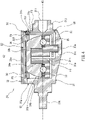
- FIG. 1 is a cross-sectional perspective view showing the configuration of an aircraft electricity generation apparatus (drive mechanism-integrated electricity generation apparatus for an aircraft) 1 according to an exemplary embodiment.
- This electricity generation apparatus may be hereinafter referred to as "electricity generation apparatus 1".
- the electricity generation apparatus 1 is a drive mechanism-integrated electricity generation apparatus.
- the electricity generation apparatus 1 includes: an input mechanism 2 that inputs rotational drive power from a rotational shaft of an engine of an aircraft to a transmission (toroidal continuously variable transmission) 3; the transmission 3 disposed in parallel to the input mechanism 2; an electricity generator 4 disposed in parallel to the input mechanism 2 and transmission 3 and driven by output of the transmission 3; a power transfer mechanism 5 located toward a first axial end 2a of the input mechanism 2 to transmit the output of the transmission 3 to the electricity generator 4; a casing 6 including a mounting portion 6a located toward the first axial end 2a of the input mechanism 2; and accessory devices including oil pumps 7 and 8 driven by the output of the transmission 3.
- the input mechanism 2 transmits the rotational drive power of the engine to the transmission 3.
- the input mechanism 2 includes a shaft main body 9 and a transfer gear 10 located toward a second axial end 2c that is in proximity to the transmission input gear 11, the transfer gear 10 being close to one end of the shaft main body 9.
- the transfer gear 10 is in mesh with the transmission input gear 11.
- the input mechanism 2 is rotatably supported by a bearing B1 located around the circumference of an opening 6b of the casing 6 and a bearing B2 located inside the casing 6.
- the electricity generator 4 includes an electricity generator input shaft 12 located toward the first axial end 2a of the input mechanism 2 which is in proximity to the opening 6b of the casing 6.
- the electricity generator input shaft 12 serves to input drive power to the electricity generator 4.
- the electricity generator 4 generates electricity therein, and the generated electricity is drawn through a terminal 13 projecting out of the casing 6.
- the speed ratio of the transmission 3 is adjusted so that the output of the transmission 3 is input to the electricity generator input shaft 12 through the power transfer mechanism 5 in the form of rotational drive power that produces rotation at a given speed.
- AC power with a given frequency is generated by the electricity generator 4 and supplied to an external device through the terminal 13.
- the power transfer mechanism 5 transmits the output of the transmission 3 to the electricity generator 4 and other devices such as the oil pumps 7 and 8.
- the oil pump 7 is an oil feed pump that feeds a lubricating oil to components such as the transmission 3 and power transfer mechanism 5.
- the oil pump 8 is an oil suction pump that sucks in the oil retained in the casing 6.
- the casing 6 is shaped as a thin, elongated, flattened box.
- the mounting portion 6a is an annular flange located at one side surface of the casing 6.
- the electricity generation apparatus 1 is mounted to the engine by winding a mounting tool such as a clamping band around the mounting portion 6a.
- a mounting tool such as a clamping band around the mounting portion 6a.
- the opening 6b communicating with the interior of the casing 6.
- the first axial end 2a of the input mechanism 2 projects out of the opening 6b.
- the transmission 3 is a continuously variable transmission of the traction drive type and may be, for example, a half-toroidal continuously variable transmission of the double cavity type.
- the transmission 3 includes: an input structure 22 located toward the second axial end 2c of the input mechanism 2 to receive output from the input mechanism 2; and an output structure 23 located toward the first axial end 2a of the input mechanism 2 to transmit output resulting from a speed change process to the power transfer mechanism 5.
- the transmission 3 includes: a hollow transmission input shaft 24 rotatably supported by a non-illustrated bearing inside the casing 6; and a transmission output shaft 25 inserted into the hollow interior of the transmission input shaft 24 and having an axially central portion enclosed by the transmission input shaft 24, the transmission output shaft 25 being rotatable independently of the transmission input shaft 24.
- the rotational centers of the transmission input and output shafts 24 and 25 coincide with the axial centerline of the transmission.
- the axial centerline of the transmission will hereinafter be referred to as "transmission axis A1".
- the transmission 3 includes: the transmission input gear 11 which functions as an element of the input structure 22; a pair of input discs 26 mounted respectively on opposite surfaces of the transmission input gear 11; and a pair of output discs 27 mounted on the transmission output shaft 25, each output disc 27 being opposed to a corresponding one of the input discs 26.
- the transmission input gear 11 and the pair of input discs 26 are rotatable about the transmission axis A1 together with the transmission input shaft 24.
- the pair of output discs 27 are rotatable about the transmission axis A1 together with the transmission output shaft 25.
- An annular cavity 28 is located between the input and output discs 26 and 27 opposed to each other. The two cavities 28 extend around the transmission axis A1 and are aligned in the direction of the transmission axis A1.
- one of the output discs 27 that is closer to the mounting portion 6a than the other output disc 27 functions as an element of the output structure 23.
- the transmission 3 includes speed change units 29 disposed in the cavities 28.
- FIG. 2 is a perspective view showing the configuration of the speed change unit 29.
- FIG. 3 is a partially exploded perspective view of the speed change unit 29.
- FIG. 4 is a cross-sectional view of the speed change unit 29 taken along the line IV-IV of FIG. 2 .
- the speed change unit 29 is an assembly constructed of a power roller unit 30, a trunnion 31, and a beam (discharge structure) 32.
- two of the speed change units 29 are arranged in parallel in each of the pair of cavities 28 aligned in the direction of the transmission axis A1.
- the power roller unit 30 is supported by the trunnion 31. As shown in FIG. 4 , the power roller unit 30 includes: a support 33 mounted on the trunnion 31; a substantially hemispherical power roller 34 rotatably supported by the support 33; and a bearing 35 located between the support 33 and power roller 34 to rotatably support the power roller 34.
- the support 33 is a substantially disc-shaped plate and includes an eccentric shaft 33a projecting toward the trunnion 31.
- the support 33 is supported at the eccentric shaft 33a by the trunnion 31.
- the support 33 further includes a roller rotational shaft 33b projecting along a rotational axis A2 in a direction opposite to that in which the eccentric shaft 33a projects.
- the power roller 34 includes a recessed, rotatably supported portion 34a that faces the roller rotational shaft 33b.
- the roller rotational shaft 33b is inserted into the rotatably supported portion 34a to rotatably support the power roller 34 so that the power roller 34 is rotatable about the axis of the roller rotational shaft 33b.
- the power roller 34 is rotatably supported about the rotational axis A2.
- the circumferential surface 34b of the power roller 34 is a gently curved surface. During operation, the lubricating oil forms an oil film on the circumferential surface 34b of the power roller 34.
- the transmission 3 includes a non-illustrated pressing mechanism located in the vicinity of either of the output discs 27 to hold the circumferential surface 34b of each power roller 34 between the input and output discs 26 and 27 with a given pressing force. While being pressed by the pressing mechanism, the power roller 34 is tiltably held between a roller-facing surface 26a of the input disc 26 and a roller-facing surface 27a of the output disc 27, with the oil film interposed between the power roller 34 and the roller-facing surfaces 26a and 27a.
- the transmission 3 uses the viscous resistance of the oil film (fluid friction) to transmit the rotational drive power of the input disc 26 to the output disc 27 through the power roller 34.
- the trunnion 31 supports the power roller unit 30 while covering a part of the circumferential surface 34b.
- the trunnion 31 is pivotable (tiltable) about a tilt axis A3.
- the trunnion 31 tilts together with the power roller 34.
- the tilt axis A3 is skew to the transmission axis A1 and perpendicular to the rotational axis A2 ( FIG. 1 ). As shown in FIGS.
- the trunnion 31 includes: a base 31a which extends in the direction of the tilt axis A3 and on which the power roller unit 30 is mounted; and a pair of side walls 31b and 31c rising from the base 31a, the side walls 31b and 31c being opposed across the power roller unit 30 in the direction of the tilt axis A3 (the axial direction of tilt shafts) and facing the circumferential surface 34b of the power roller 34.
- the base 31a includes a rotatably supporting portion 31d located in one surface of the base 31a to rotatably support the eccentric shaft 33a.
- the pair of side walls 31b and 31c project respectively from both longitudinal ends of the base 31a, and a space G1 accommodating the power roller 34 is defined between the pair of side walls 31b and 31c.
- the thickness direction of the pair of side walls 31b and 31c coincides with the direction of the tilt axis A3.
- the pair of side walls 31b and 31c include end surfaces 31e and 31f, respectively, the end surfaces 31e and 31f being located at distal ends of the side walls 31b and 31c in the direction in which the side walls 31b and 31c rise.
- the end surfaces 31e and 31f include grooves 31g and 31h, respectively, the grooves 31g and 31h being located at the centers of the end surfaces 31e and 31f.
- the grooves 31g and 31h are formed by recessing the central regions of the end surfaces 31e and 31f. As shown in FIG. 3 , the grooves 31g and 31h are open at both ends in the direction of the tilt axis A3.
- Each of the side walls 31b and 31c includes insertion holes 31i extending through the entire thickness of the side wall 31b or 31c in the direction of the tilt axis A3.
- Tilt shafts (short shaft 31j and long shaft 31k) extending in the direction of the tilt axis A3 are located outside the pair of side walls 31b and 31c when viewed from the power roller unit 30.
- a non-illustrated actuator is coupled to either the short shaft 31j or long shaft 31k.
- each of the speed change units 29 is supported at its short and long shafts 31j and 31k so as to be tiltable about the tilt axis A3.
- the power roller 34 is rotatable about the tilt axis A3.
- the tilt angle of the speed change unit 29 (the angle of rotation relative to a reference position about the tilt axis A3) can be adjusted by moving the power roller 34 relative to the input and output discs 26 and 27 in the direction of the tilt axis A3 with the use of the actuator.
- the power roller 34 transmits the rotational drive power of the input disc 26 to the output disc 27 at a speed ratio determined by the tilt angle.
- the beam 32 is located across the power roller 34 from the base 31a of the trunnion 31, and extends in the direction of the tilt axis A3 (the axial direction of the tilt shafts).
- the beam 32 is mounted on the pair of side walls 31b and 31c to reinforce the trunnion 31.
- the beam 32 is in an elongated shape extending in the direction of the tilt axis A3.
- the beam 32 includes: an elongated body portion 32g extending between the pair of side walls 31b and 31c; a pair of contact portions 32a located near to both longitudinal ends of the body portion 32g, respectively; and four extension portions 32c extending in the transverse direction (width direction) of the beam 32.
- the pair of contact portions 32a are fitted into the grooves 31g and 31h, respectively, and thus the beam 32 is mounted on the pair of side walls 31b and 31c.
- the beam 32 is blocked from moving toward the base 31a of the trunnion 31 and blocked from moving in the transverse direction (i.e., a direction perpendicular to both the direction of the tilt axis A3 and the direction in which the side walls 31b and 31c rise).
- the extension portions 32c include insertion holes 32d that are aligned with the insertion holes 31i when the beam 32 is combined with the trunnion 31.
- the beam 32 is threadedly secured to the trunnion 31 at several points by fasteners PI such as screws laterally inserted into the insertion holes 31i and 32d from outside the pair of side walls 31b and 31c.
- fasteners PI such as screws laterally inserted into the insertion holes 31i and 32d from outside the pair of side walls 31b and 31c.
- the beam 32 is coupled to the pair of side walls 31b and 31c.
- the structure for mounting the beam 32 on the trunnion 31 is not limited to that as described above, and any of various structures may be used to mount the beam 32 on the trunnion 31.
- Two of the extension portions 32c are located close to one longitudinal end of the beam 32 and at a given distance from the inner surface of the side wall 31b, and the other two of the extension portions 32c are located close to the other longitudinal end of the beam 32 and at a given distance from the inner surface of the side wall 31c.
- the extension portions 32c extend toward the upper surface of the base 31a and the circumferential surface 34b of the power roller 34.
- the speed change unit 29 includes oil passages F1 to F6 located inside the power roller unit 30, trunnion 31, and beam 32 to allow an oil for discharge toward the power roller 34 to flow inside the power roller unit 30, trunnion 31, and beam 32.
- the oil passages F1 to F3 are parts of a first oil passage E1 located inside the trunnion 31.
- the oil passages F4 to F6 are parts of a second oil passage E2 located inside the beam 32 and connected to the first oil passage E1.
- the trunnion 31 includes: the oil passage F1 originating from a first opening 311 located at the end surface of the short shaft 31j, passing inside the base 31a, and leading to the rotatably supporting portion 31d and a second opening 31m located at the upper surface of the base 31a; and the oil passage F2 branching from the oil passage F1, passing inside the side wall 31c, and leading to a third opening 31n located at the surface of the groove 31h in the end surface 31f of the side wall 31c.
- the power roller unit 30 includes the oil passage F3 extending through the entire thickness of the support 33.
- the oil is fed to components such as the bearing 35 of the power roller unit 30 through the oil passage F3.
- the beam 32 includes a fourth opening 32f located at the surface of the contact portion 32a which is in contact with the end surface 31f at which the third opening portion 31n is located.
- the beam 32 further includes: the oil passage F4 extending from the fourth opening 32f along the thickness of the beam 32 in a direction away from the trunnion 31 and bent at a given point to extend along the length of the beam 32; the oil passage F5 branching from the oil passage 4 toward one end of the width of the beam 32 at a point located toward one longitudinal end of the beam 32, the oil passage F5 extending inside one of the extension portions 32c in a direction in which the one extension portions 32c extends, the one extension portion 32c being that located toward the one longitudinal end; and the oil passage F6 branching from the oil passage 4 to the other end of the width of the beam 32 at a point located toward the other longitudinal end of the beam 32, the oil passage F6 extending inside another of the extension portions 32c in a direction in which the other extension portion 32c extends, the other extension portion
- FIG. 5 is a schematic plan view of the speed change unit 29 as viewed along the rotational axis A2 of the power roller 34.
- a first outlet (outlet) 51 is located in the vicinity of the downstream end of the oil passage F5.
- a second outlet (outlet) 52 is located in the vicinity of the downstream end of the oil passage F6. Both the first and second outlets 51 and 52 are directed toward the circumferential surface of the power roller 34.
- the beam 32 and power roller 34 are arranged such that the beam 32 and the circumferential surface of the power roller 34 face each other, and the beam 32 is disposed such that both the first and second outlets 51 and 52 are directed toward the circumferential surface of the power roller 34.
- the first and second outlets 51 and 52 are point-symmetric with respect to the rotational axis A2 of the power roller 34.
- the first and second outlets 51 and 52 discharge the oil toward the power roller 34.
- the first and second outlets 51 and 52 have a circular shape.
- the positional relationship of the input and output discs 26 and 27 with the beam 32, trunnion 31, and power roller 34 may be reversed.
- FIG. 6A is a schematic perspective view showing the oil passage F5, the first outlet 51, and a jet of oil HI discharged from the first outlet 51
- FIG. 6B is a schematic front view showing the oil passage F5, the first outlet 51, and the jet of oil H1.
- the direction in which an oil passage F5a extends is defined as a direction D1.
- the width direction of the oil passage F5a, which is perpendicular to the direction D1 in a plane perpendicular to the rotational axis A2 of the power roller 34 of FIG. 5 is defined as a direction D2.
- the direction in which the rotational axis A2 of the power roller 34 of FIG. 5 extends is defined as a direction D3.
- the oil passage F5 includes: the oil passage F5a branching from the oil passage F4 and extending downstream in the oil flow direction; a first oil passage F5b extending from a bend at the downstream end of the oil passage F5a toward the power roller 34; and a second oil passage F5c branching from the oil passage F5a at a point upstream of the first oil passage F5b and extending toward the power roller 34.
- the first and second oil passages F5b and F5c are inclined such that the first and second oil passages F5b and F5c become closer to each other as they extend downstream.
- the first and second oil passages F5b and F5c join together at the downstream end in the direction D3, and the first outlet 51 common to the first and second oil passages F5b and F5c is located at the common downstream end of the first and second oil passages F5b and F5c.
- FIG. 6A a flow path cross-section f1 of the first oil passage F5b and a flow path cross-section f2 of the second oil passage F5c are shown.
- a flow path centerline L1 of the first oil passage F5b and a flow path centerline L2 of the second oil passage F5c are also shown in FIG. 6A .
- the centerline L1 of the first oil passage F5b and the centerline L2 of the second oil passage F5c intersect inside the first outlet 51.
- the first outlet 51 opens at an end surface 32e of the beam 32.
- the first outlet 51 is located in a surface defining the end surface 32e of the beam 32.
- the centerlines L1 and L2 intersect inside the first outlet 51. That is, an intersection C1 between the centerlines L1 and L2 is located in a plane including the end surface 32e of the beam 32 at which the first outlet 51 is located.
- the first and second oil passages F5b and F5c are arranged such that an angle ⁇ between the centerlines L1 and L2 is from 30° to 50° (e.g., 40°).
- the second outlet 52 which is point-symmetric to the first outlet 51 with respect to the rotational axis A2 of the power roller 34, is arranged in the same manner as the first outlet 51.
- the oil pump 7 is operated to allow the oil to flow through the oil passages F1 to F6 of the speed change unit 29 and be discharged from each of the first and second outlets 51 and 52 for the purpose of cooling the power roller 34.
- the jet of oil HI discharged from the first outlet 51 does not spread in the direction D1 in which the first and second oil passages F5b and F5c face each other, but spreads only in the direction D2 perpendicular to the direction in which the first and second oil passages F5b and F5c face each other while moving downstream in the direction D3.
- the reason is as follows: the oil flowing through the first oil passage F5b and the oil flowing through the second oil passage F5c collide with each other, and the kinetic momenta of the two oil flows in the direction D1 cancel each other, so that the jet of oil HI does not spread in the direction D1 but in the direction D2 while moving downstream in the direction D3.
- the jet of oil HI discharged from the first outlet 51 forms a flattened shape extending not in the direction D1 but only in the direction D2.
- FIG. 7 is a cross-sectional view for describing the positional relationship among the oil passage F5a, first oil passage F5b, and second oil passage F5c in the beam 32
- FIG. 8 is a perspective view showing the oil passage F5a, first oil passage F5b, and second oil passage F5c.
- an extension of the first oil passage F5b from the first outlet 51 is assumed as an imaginary oil passage F7
- an extension of the second oil passage F5c from the first outlet 51 is assumed as an imaginary oil passage F8.
- An oil passage F9 formed by the first oil passage F5b and imaginary oil passage F7 and an oil passage F10 formed by the second oil passage F5c and imaginary oil passage F8 intersect with each other, and an overlap region VI between the oil passages F9 and F10 is situated across the first outlet 51.
- the portion of the overlap region VI that is closer to the oil passage F5a than the first outlet 51 is defined as a beam-side overlap region V2.
- the portion of the overlap region VI that is closer to the power roller 34 than the first outlet 51 is defined as a power roller-side overlap region V3.
- the first outlet 51 is located between the beam-side overlap region V2 and the power roller-side overlap region V3.
- the overlap region VI intersects with the end surface 32e.
- the first oil passage F5b in the shape of a cylindrical tube and the second oil passage F5c in the shape of a cylindrical tube intersect such that a surface S1 (connection region) is defined by the lines of intersection between the cylindrical tube-shaped first and second oil passages F5b and F5c in the region over which the first and second oil passages F5b and F5c intersect (are connected) with each other.
- the surface S1 is shaped as a part of a circle or an ellipse since each of the first and second oil passages F5b and F5c is in the shape of a cylindrical tube.
- the intersection C1 is located in the same plane as the end surface 32e.
- the oil flowing through the first oil passage F5b and the oil flowing through the second oil passage F5c invariably collide with each other inside the first and second oil passages F5b and F5c, and the resulting oil flow is discharged from the first outlet 51.
- the wall surfaces defining the first and second oil passages F5b and F5c can guide the oil flowing through the first oil passage F5b and the oil flowing through the second oil passage F5c until these oil flows collide with each other.
- the oil flowing through the first oil passage F5b and the oil flowing through the second oil passage F5c can invariably collide with each other.
- FIG. 9 is a schematic perspective view showing the oil passage F5, the first outlet 51, the jet of oil HI discharged from the first outlet 51, and the power roller 34 as viewed when the oil is discharged toward the power roller 43 from the first outlet 51 of the beam 32 constructed as described above.
- the rotational direction of the power roller 34 is denoted by R1
- the direction of an ambient air flow entrained by the rotation of the power roller 34 is denoted by W1. Since the jet of oil HI is discharged after collision between the oil flowing through the first oil passage F5b and the oil flowing through the second oil passage F5c, the jet of oil HI forms a flattened shape having a thickness T1 in the direction D1. As such, the jet of oil HI forms a flattened fan-like or triangular shape.
- the oil passage F5 is disposed such that the direction D1 in which the oil passage F5a extends coincides with a radial direction D4 of the power roller 34.
- the first and second oil passages F5b and F5c face each other in the radial direction D4 of the power roller 34.
- the jet of oil HI discharged from the first outlet 51 does not spread in the radial direction D4 of the power roller 34, but spreads in a tangential direction D5 of the circumferential surface 34b which is perpendicular to the radial direction D4 of the power roller 34.
- the jet of oil HI discharged from the first outlet 51 spreads in the tangential direction D5 of the circumferential surface 34b of the power roller 34 and does not spread in the radial direction D4 of the power roller 34.
- the jet of oil HI can be shaped to be resistant to the influence of a wind generated by rotation of the power roller 34.
- the jet of oil HI is thin in the radial direction D4 of the power roller 34, and as such the portion of the jet of oil HI that faces in the air flow direction W1 can have a small area.
- the jet of oil HI is created such that in the event that rotation of the power roller 34 in the direction R1 generates a wind flowing in the direction W1, the portion of the jet of oil HI that faces the wind flowing in the direction W1 has a small area.
- the jet of oil HI can be shaped to be resistant to the influence of a wind flowing in the direction W1. In the event of a wind flowing in the direction W1, the jet of oil HI can resist being blown off by the wind.
- the jet of oil HI can be shaped to resist being blown off by a wind generated by rotation of the power roller 34, the jet of oil HI can be efficiently used to cool the power roller 34. Thus, reduction in the performance in cooling of the power roller 34 can be prevented, and high cooling performance can be achieved.
- the first and second oil passages F5b and F5c are arranged to face each other in the radial direction D4 of the power roller 34 such that the jet of oil HI forms a flattened shape that is long in the tangential direction D5 of the circumferential surface 34b of the power roller 34 and short in the radial direction of the power roller 34.
- the present invention is not limited to this configuration of the above embodiment.
- the direction in which the first and second oil passages F5b and F5c face each other need not be exactly the same as the radial direction D4 of the power roller 34.
- the first and second oil passages F5b and F5c may face each other in any direction so long as the jet of oil HI discharged from the first outlet 51 is shaped to be resistant to the influence of a wind generated by rotation of the power roller 34 and flowing in the direction W1.
- the jet of oil HI only needs to be thin in the radial direction D4 of the power roller 34, and the direction in which the jet of oil HI is extended need not coincide with the tangential direction D5 of the circumferential surface 34b of the power roller 34.
- the direction in which the jet of oil HI is extended may be slightly inclined with respect to the tangential direction D5 of the circumferential surface 34b of the power roller 34.
- the direction in which the jet of oil HI is extended may have a component which is in the tangential direction D5 of the circumferential surface 34b of the power roller 34 such that the portion of the jet of oil HI that faces a wind flowing in the direction W1 has a small area.
- first and second oil passages F5b and F5c need not be arranged to face each other in a direction that is exactly the same as the radial direction D4 of the power roller 34.
- the direction in which the first and second oil passages F5b and F5c face each other may be inclined with respect to the radial direction D4 of the power roller 34 so long as the portion of the jet of oil HI that faces a wind flowing in the direction W1 has a small area.
- first outlet 51, first oil passage F5b, and second oil passage F5c are arranged such that the intersection C1 between the centerline L1 of the first oil passage F5b and the centerline L2 of the second oil passage F5c is located at the surface at which the first outlet 51 is located.
- present invention is not limited to this configuration of the above embodiment.
- the intersection C1 between the centerlines L1 and L2 need not be located at the surface at which the first outlet 51 is located.
- FIG. 10A is a cross-sectional view showing the oil passage F5a, first oil passage F5b, and second oil passage F5c of the beam 32 in an embodiment where the intersection C1 is located at a point closer to the power roller 34 than the surface at which the first outlet 51 is located (external point in the oil discharge direction), and FIG. 10B is a perspective view showing the oil passage F5a, first oil passage F5b, and second oil passage F5c.
- the “external point in the oil discharge direction” refers to a point downstream of the first outlet 51 in the direction in which the oil is discharged.
- the “internal point in the oil discharge direction” as described below refers to a point located across the first outlet 51 from the external point and inside the first outlet 51 in the direction from the power roller 34 toward the first outlet 51.
- the oil flowing through the first oil passage F5b and the oil flowing through the second oil passage F5c can be made to collide with each other inside the first or second oil passage F5b or F5c so long as the first and second oil passages F5b and F5c are arranged such that the oil flows collide with each other in the vicinity of the first outlet 51.
- the oil flowing through the first oil passage F5b and the oil flowing through the second oil passage F5c collide with each other at the internal point upstream of the first outlet 51 in the oil discharge direction
- the oil flows can be made to collide with each other inside the first or second oil passage F5b or F5c.
- the jet of oil HI discharged from the first outlet 51 can form a flattened shape as shown in FIG. 9 .
- the oil flowing through the first oil passage F5b and the oil flowing through the second oil passage F5c can be made to collide with each other in the vicinity of the first outlet 51 in the case where the intersection C1 is closer to the power roller 34 than the first outlet 51 but in the vicinity of the first outlet 51.
- the intersection C1 need not be located at the surface at which the first outlet 51 is located, and may be in the vicinity of the first outlet 51.
- intersection C1 need not be located at the surface at which the first outlet 51 is located so long as the centerline L1 of the first oil passage F5b and the centerline L2 of the second oil passage F5c intersect at a point in the vicinity of the first outlet 51 such that that the oil flowing through the first oil passage F5b and the oil flowing through the second oil passage F5c invariably collide with each other.
- the "point in the vicinity of the first outlet 51" refers to the location of the intersection C1 located such that the overlap region VI between the intersecting oil passages F9 and F10 intersects with the end surface 32e of the beam 32.
- the oil flowing through the first oil passage F5b and the oil flowing through the second oil passage F5c collide with each other around the first outlet 51, and the oil flow resulting from the collision is immediately discharged from the first outlet 51.
- the wall surfaces defining the first and second oil passages F5b and F5c guide the oil flowing through the first oil passage F5b and the oil flowing through the second oil passage F5c, respectively, to ensure that the oil flows collide with each other.
- the oil flow resulting from the collision inside the first or second oil passage F5b or F5c is immediately discharged from the first outlet 51 toward the power roller 34.
- the jet of oil discharged from the first outlet 51 forms a flattened shape as shown in FIG. 9 .
- the first and second oil passages F5b and F5c are arranged such that the surface S1 intersects with that end surface 32e of the beam 32 at which the first outlet 51 is located. Since the centerlines L1 and L2 of the first and second oil passages F5b and F5c intersect at a point in the vicinity of the first outlet 51, the surface S1 intersects with the end surface 32e. Although the centerlines L1 and L2 of the first and second oil passages F5b and F5c do not intersect at the end surface 32e in which the first outlet 51 is located, the surface S1 intersects with the end surface 32e since the centerlines L1 and L2 intersect at a point in the vicinity of the first outlet 51.
- the intersection C1 is located in the vicinity of the first outlet 51 such that the surface S1 intersects with the end surface 32e
- the oil flowing through the first oil passage F5b and the oil flowing through the second oil passage F5c can be made to collide with each other in the vicinity of the first outlet 51.
- the jet of oil HI discharged from the first outlet 51 can form a flattened shape as shown in FIG. 6 or 7 .
- FIG. 11A is a cross-sectional view showing the oil passage F5a, first oil passage F5b, and second oil passage F5c of the beam 32 in an embodiment where the intersection C1 is located at an internal point upstream of the end surface 32e in the oil discharge direction
- FIG. 11B is a perspective view showing the oil passage F5a, first oil passage F5b, and second oil passage F5c.
- the intersection C1 is closer to the oil passage F5a than that end surface 32e of the beam 32 at which the first outlet 51 is located, the oil flowing through the first oil passage F5b and the oil flowing through the second oil passage F5c can be made to collide with each other inside the first or second oil passage F5b or F5c so long as the first and second oil passages F5b and F5c are arranged such that the oil flows collide with each other in the vicinity of the first outlet 51.
- the jet of oil HI discharged from the first outlet 51 can form a flattened shape as shown in FIG. 9 .
- intersection C1 is located upstream and in the vicinity of the first outlet 51 in the oil discharge direction, the oil flowing through the first oil passage F5b and the oil flowing through the second oil passage F5c can be made to collide with each other in the vicinity of the first outlet 51.
- the intersection C 1 need not be located at the surface at which the first outlet 51 is located, and may be in the vicinity of the first outlet 51.
- the intersection C1 Since the intersection C1 is located in the vicinity of the first outlet 51, the overlap region VI between the intersecting oil passages F9 and F10 intersects with the end surface 32e as shown in FIGS. 11A and 11B .
- the oil flowing through the first oil passage F5b and the oil flowing through the second oil passage F5c collide with each other around the first outlet 51, and the oil flow resulting from the collision is discharged from the first outlet 51.
- the wall surfaces defining the first and second oil passages F5b and F5c guide the oil flowing through the first oil passage F5b and the oil flowing through the second oil passage F5c, respectively, to ensure that the oil flows invariably collide with each other.
- the oil flow resulting from the collision inside the first or second oil passage F5b or F5c is immediately discharged from the first outlet 51 toward the power roller 34.
- the jet of oil discharged from the first outlet 51 forms a flattened shape as shown in FIG. 9 .
- the first and second oil passages F5b and F5c are arranged such that the surface S1 intersects with the end surface 32e.
- the intersection C1 is located in the vicinity of the first outlet 51 such that the surface S1 intersects with the end surface 32e
- the oil flowing through the first oil passage F5b and the oil flowing through the second oil passage can be made to collide with each other in the vicinity of the first outlet 51.
- the jet of oil HI discharged from the first outlet 51 can form a flattened shape as shown in FIG. 9 .
- each of the first and second oil passages F5b and F5c is in the shape of a cylindrical tube, and the surface S1 defined as the connection region is circular or elliptical.
- the present invention is not limited to such a configuration of the above embodiments, and the first and second oil passages F5b and F5c may have a shape other than the shape of a cylindrical tube.
- the first and second oil passages F5b and F5c may be in the shape of a tube having a square or rectangular cross-section.
- the present invention is not limited to such a configuration of the above embodiments.
- the angle ⁇ between the centerlines L1 and L2 may be smaller or larger than 40°.
- the angle ⁇ between the centerlines L1 and L2 is preferably 80° or less. If the angle ⁇ between the centerlines L1 and L2 is excessively large, the thickness T1 ( FIG. 9 ) of the jet of oil HI discharged from the first outlet 51 is excessively small.
- FIG. 12 is a graph showing the change in cooling performance with respect to the angle between the first and second oil passages F5b and F5c.
- the performance in cooling of the power roller 34 decreases with increasing angle ⁇ .
- the thickness T1 of the jet of oil HI gradually decreases with increasing angle ⁇ . If the thickness T1 of the jet of oil HI is excessively small, most of the jet of oil HI discharged from the first outlet 51 is blown off by a wind flowing in the direction W1 before reaching the power roller 34. Thus, the oil discharged from the first outlet 51 cannot be used fully to cool the power roller 34, and the performance in cooling of the power roller 34 is reduced.
- the angle ⁇ between the centerlines L1 and L2 is larger than 80°, the thickness T1 of the jet of oil is excessively small, and for this reason the performance in cooling of the power roller 34 is lower than in the case where a jet of oil is discharged through a single oil passage rather than through both the first and second oil passages F5b and F5c branching from the oil passage F5a.
- the angle ⁇ between the centerlines L1 and L2 is preferably 80° or less.
- the first outlet 51 located toward one longitudinal end of the beam 32 and the second outlet 52 located toward the other longitudinal end of the beam 32 are identical, and the first and second oil passages F5b and F5c connected to the first outlet 51 and the first and second oil passages connected to the second outlet 52 are identical.
- the jet of oil discharged from the second outlet 52 forms the same shape as the jet of oil HI discharged from the first outlet 51.
- each speed change unit 29 includes two outlets, and both of the two outlets discharge the oil such that the jet of oil discharged from each outlet is shaped to be resistant to the influence of a wind generated by rotation of the power roller 34.
- the present invention is not limited to such a configuration of the above embodiments.
- each speed change unit includes two or more outlets, it is not essential that all of the outlets discharge the oil such that the jets of oil discharged from the outlets are shaped to be resistant to the influence of a wind generated by rotation of the power roller 34.
- each speed change unit includes two outlets as in the embodiments described above, only one of the two outlets may discharge the oil such that the jet of oil discharged from the one outlet is shaped to be resistant to the influence of a wind generated by rotation of the power roller 34.
- each speed change unit includes two or more outlets, it is only required that at least one of the outlets should discharge the oil such that the jet of oil discharged from the at least one outlet is shaped to be resistant to the influence of a wind generated by rotation of the power roller 34.
- the first and second outlets 51 and 52 are included in the beam 32, and the beam 32 functions as the discharge structure including outlets.
- the present invention is not limited to such a configuration of the above embodiments, and outlets may be included in an element other than the beam 32.
- the trunnion 31 may further include a portion located across the power roller 34 from the base 31a and extending in the direction of the tilt axis A3, and outlets may be included in this portion of the trunnion 31.
- the trunnion 31 functions as the discharge structure including outlets.
- Another element may function as the discharge structure. That is, the discharge structure may be any element other than the beam 32 and trunnion 31 so long as the discharge structure includes outlets that discharge the oil toward the power roller 34.
- the first and second oil passages F5b and F5c are arranged such that the oil flowing through the first oil passage F5b and the oil flowing through the second oil passage F5c collide with each other in the vicinity of the first outlet 51 and that the jet of oil discharged from the first outlet 51 forms a flattened shape extending along the rotational direction of the power roller 34.
- the portion of the jet of oil HI that faces in the rotational direction of the power roller 34 has a small area.
- the jet of oil HI can be shaped to resist being blown off by a wind generated by rotation of the power roller 34. Therefore, a sufficient amount of oil can be fed to the power roller 34 to efficiently cool the power roller 34.
- the first and second oil passages F5b and F5c are arranged such that the surface S1 intersects with the end surface 32e, and this ensures that the first and second oil passages F5b and F5c are connected with each other in the vicinity of the end surface 32e.
- the wall surfaces defining the first and second oil passages F5b and F5c guide the oil flowing through the first oil passage F5b and the oil flowing through the second oil passage F5c, respectively, to ensure that the oil flows collide with each other in the vicinity of the first outlet 51.
- the oil flowing through the first oil passage F5b and the oil flowing through the second oil passage F5c invariably collide with each other, and the oil flow resulting from the collision is discharged from the first outlet 51, so that the jet of oil HI invariably forms a flattened shape.
- the first and second oil passages F5b and F5c are arranged such that the jet of oil HI is extended along the rotational direction of the power roller 34, the portion of the jet of oil HI that faces in the rotational direction of the power roller 34 has a small area.
- the jet of oil HI can be shaped to resist being blown off by a wind generated by rotation of the power roller 34. As such, a sufficient amount of oil can be fed to the power roller 34 to efficiently cool the power roller 34.
- the power roller 34 can be efficiently cooled by the jet of oil HI.
- the oil amount in the jet of oil HI discharged to cool the power roller 34 can be reduced.
- the oil pump 7, oil cooler, oil tank, oil piping line, and other related devices used in the aircraft electricity generation apparatus 1 can be downsized. This allows for reduced weight and improved fuel economy of the aircraft. Additionally, churning of the oil by the oil pump 7 can be reduced to decrease the churning loss in the oil pump 7. Thus, the fuel economy of the aircraft can be further improved.
- An increase in the amount of the oil to be fed could lead to size increase of the devices such as the oil pump 7, oil cooler, oil tank, and oil piping line used in the aircraft electricity generation apparatus 1 and therefore weight increase of the aircraft electricity generation apparatus 1, resulting in reduced fuel economy of the aircraft.
- the size or rotational speed of the oil pump 7 should be increased due to an increase in the amount of the oil to be discharged. In this case, the churning loss in the oil pump 7 is increased, and accordingly the heat generation from the oil under churning is increased. The increased heat generation could lead to a corresponding reduction in the efficiency of the aircraft electricity generation apparatus 1. This could result in reduced fuel economy of the aircraft.
- the electricity generation apparatus 1 is constructed using the transmission 3 that can cool the power roller 34 efficiently.
- the electricity generation apparatus 1 can be provided as an electricity generation apparatus in which the temperature increase of the power roller 34 can be minimized.
Landscapes
- Engineering & Computer Science (AREA)
- General Engineering & Computer Science (AREA)
- Mechanical Engineering (AREA)
- Power Engineering (AREA)
- Chemical & Material Sciences (AREA)
- Combustion & Propulsion (AREA)
- Aviation & Aerospace Engineering (AREA)
- Friction Gearing (AREA)
- Connection Of Motors, Electrical Generators, Mechanical Devices, And The Like (AREA)
Applications Claiming Priority (2)
| Application Number | Priority Date | Filing Date | Title |
|---|---|---|---|
| JP2019134699A JP7269123B2 (ja) | 2019-07-22 | 2019-07-22 | トロイダル無段変速機及び航空機用駆動機構一体型発電装置 |
| PCT/JP2020/025017 WO2021014880A1 (ja) | 2019-07-22 | 2020-06-25 | トロイダル無段変速機及び航空機用駆動機構一体型発電装置 |
Publications (3)
| Publication Number | Publication Date |
|---|---|
| EP4005930A1 true EP4005930A1 (de) | 2022-06-01 |
| EP4005930A4 EP4005930A4 (de) | 2023-08-02 |
| EP4005930B1 EP4005930B1 (de) | 2024-12-04 |
Family
ID=74193428
Family Applications (1)
| Application Number | Title | Priority Date | Filing Date |
|---|---|---|---|
| EP20845042.9A Active EP4005930B1 (de) | 2019-07-22 | 2020-06-25 | Stufenloses toroidgetriebe und antriebsmechanismus integrierte stromerzeugungsvorrichtung für flugzeuge |
Country Status (4)
| Country | Link |
|---|---|
| US (1) | US11913524B2 (de) |
| EP (1) | EP4005930B1 (de) |
| JP (1) | JP7269123B2 (de) |
| WO (1) | WO2021014880A1 (de) |
Family Cites Families (7)
| Publication number | Priority date | Publication date | Assignee | Title |
|---|---|---|---|---|
| US2019815A (en) * | 1933-08-05 | 1935-11-05 | Gerald J Holtham | Oil burner tip |
| JP2002106667A (ja) * | 2000-10-04 | 2002-04-10 | Honda Motor Co Ltd | トロイダル型無段変速機 |
| DE102004009409A1 (de) * | 2004-02-24 | 2006-01-26 | Daimlerchrysler Ag | Stufenlos verstellbarer Variator für ein Toroidgetriebe eines Kraftfahrzeuges |
| JP5131539B2 (ja) | 2008-05-13 | 2013-01-30 | 日本精工株式会社 | トロイダル型無段変速機 |
| JP5842403B2 (ja) | 2011-06-21 | 2016-01-13 | 日本精工株式会社 | トロイダル型無段変速機 |
| JP6709021B2 (ja) | 2015-03-09 | 2020-06-10 | 川崎重工業株式会社 | トロイダル無段変速機および駆動機構一体型発電装置 |
| JP7002283B2 (ja) * | 2017-10-27 | 2022-01-20 | 川崎重工業株式会社 | トロイダル無段変速機 |
-
2019
- 2019-07-22 JP JP2019134699A patent/JP7269123B2/ja active Active
-
2020
- 2020-06-25 US US17/628,752 patent/US11913524B2/en active Active
- 2020-06-25 WO PCT/JP2020/025017 patent/WO2021014880A1/ja unknown
- 2020-06-25 EP EP20845042.9A patent/EP4005930B1/de active Active
Also Published As
| Publication number | Publication date |
|---|---|
| US20220356930A1 (en) | 2022-11-10 |
| EP4005930B1 (de) | 2024-12-04 |
| EP4005930A4 (de) | 2023-08-02 |
| JP7269123B2 (ja) | 2023-05-08 |
| US11913524B2 (en) | 2024-02-27 |
| JP2021017953A (ja) | 2021-02-15 |
| WO2021014880A1 (ja) | 2021-01-28 |
Similar Documents
| Publication | Publication Date | Title |
|---|---|---|
| US9995310B2 (en) | Rotary pump comprising a rotor and delivery elements | |
| US9897092B2 (en) | Compressor and turbo chiller | |
| KR20140036314A (ko) | 원심 블로워 시스템 및 이를 구비하는 연료 전지 | |
| KR102427392B1 (ko) | 압축기용 디퓨저 | |
| US11280372B2 (en) | Bearing structure | |
| US20190170143A1 (en) | Fluid Machine | |
| EP3318762B1 (de) | Zweistufiger verdichter mit asymmetrischem einlasskanal in die zweiten stufe | |
| EP4005930B1 (de) | Stufenloses toroidgetriebe und antriebsmechanismus integrierte stromerzeugungsvorrichtung für flugzeuge | |
| US6910349B2 (en) | Suction connection for dual centrifugal compressor refrigeration systems | |
| JP6709021B2 (ja) | トロイダル無段変速機および駆動機構一体型発電装置 | |
| US12123413B2 (en) | Screw compressor having a plurality of branch paths with intersects and central axes | |
| US12000474B2 (en) | Toroidal continuously variable transmission and drive mechanism-integrated electricity generation apparatus for aircraft | |
| BRPI0617523A2 (pt) | rotor para uma mÁquina giratària e uma mÁquina giratària | |
| CN100420845C (zh) | 燃油泵和具有燃油泵的用于机动车内燃机的燃油供给设备 | |
| CN115698480B (zh) | 涡轮壳体和增压器 | |
| CN106402046B (zh) | 一种无扇叶式发动机冷却风扇 | |
| US11952998B2 (en) | Crankshaft, inverter compressor, and refrigeration device | |
| CN113339287B (zh) | 涡轮压缩机 | |
| CN115095555B (zh) | 调压组件及压力匹配器 | |
| US20240280162A1 (en) | Bolt-type angular gear mechanism | |
| US12173760B2 (en) | Coupling guard for a rotating member | |
| US11852162B2 (en) | Centrifugal pump assembly | |
| KR20190109960A (ko) | 원심형 압축 장치 | |
| JP2017101648A (ja) | 流路可変機構とそれを備えたエゼクタ | |
| JP2008031892A (ja) | 過給機 |
Legal Events
| Date | Code | Title | Description |
|---|---|---|---|
| STAA | Information on the status of an ep patent application or granted ep patent |
Free format text: STATUS: THE INTERNATIONAL PUBLICATION HAS BEEN MADE |
|
| PUAI | Public reference made under article 153(3) epc to a published international application that has entered the european phase |
Free format text: ORIGINAL CODE: 0009012 |
|
| STAA | Information on the status of an ep patent application or granted ep patent |
Free format text: STATUS: REQUEST FOR EXAMINATION WAS MADE |
|
| 17P | Request for examination filed |
Effective date: 20220203 |
|
| AK | Designated contracting states |
Kind code of ref document: A1 Designated state(s): AL AT BE BG CH CY CZ DE DK EE ES FI FR GB GR HR HU IE IS IT LI LT LU LV MC MK MT NL NO PL PT RO RS SE SI SK SM TR |
|
| DAV | Request for validation of the european patent (deleted) | ||
| DAX | Request for extension of the european patent (deleted) | ||
| A4 | Supplementary search report drawn up and despatched |
Effective date: 20230703 |
|
| RIC1 | Information provided on ipc code assigned before grant |
Ipc: F16H 57/04 20100101ALI20230627BHEP Ipc: H02K 7/10 20060101ALI20230627BHEP Ipc: F16H 15/38 20060101ALI20230627BHEP Ipc: B64D 41/00 20060101AFI20230627BHEP |
|
| STAA | Information on the status of an ep patent application or granted ep patent |
Free format text: STATUS: EXAMINATION IS IN PROGRESS |
|
| 17Q | First examination report despatched |
Effective date: 20240405 |
|
| GRAP | Despatch of communication of intention to grant a patent |
Free format text: ORIGINAL CODE: EPIDOSNIGR1 |
|
| STAA | Information on the status of an ep patent application or granted ep patent |
Free format text: STATUS: GRANT OF PATENT IS INTENDED |
|
| INTG | Intention to grant announced |
Effective date: 20240819 |
|
| GRAS | Grant fee paid |
Free format text: ORIGINAL CODE: EPIDOSNIGR3 |
|
| GRAA | (expected) grant |
Free format text: ORIGINAL CODE: 0009210 |
|
| STAA | Information on the status of an ep patent application or granted ep patent |
Free format text: STATUS: THE PATENT HAS BEEN GRANTED |
|
| AK | Designated contracting states |
Kind code of ref document: B1 Designated state(s): AL AT BE BG CH CY CZ DE DK EE ES FI FR GB GR HR HU IE IS IT LI LT LU LV MC MK MT NL NO PL PT RO RS SE SI SK SM TR |
|
| REG | Reference to a national code |
Ref country code: CH Ref legal event code: EP |
|
| REG | Reference to a national code |
Ref country code: DE Ref legal event code: R096 Ref document number: 602020042691 Country of ref document: DE |
|
| REG | Reference to a national code |
Ref country code: IE Ref legal event code: FG4D |