EP4005884A1 - Bremslösungsmechanismus für einen federspeicherbremszylinder und zugehöriger federspeicherbremszylinder - Google Patents
Bremslösungsmechanismus für einen federspeicherbremszylinder und zugehöriger federspeicherbremszylinder Download PDFInfo
- Publication number
- EP4005884A1 EP4005884A1 EP20209724.2A EP20209724A EP4005884A1 EP 4005884 A1 EP4005884 A1 EP 4005884A1 EP 20209724 A EP20209724 A EP 20209724A EP 4005884 A1 EP4005884 A1 EP 4005884A1
- Authority
- EP
- European Patent Office
- Prior art keywords
- actuator
- release mechanism
- pin
- limiting element
- spring
- Prior art date
- Legal status (The legal status is an assumption and is not a legal conclusion. Google has not performed a legal analysis and makes no representation as to the accuracy of the status listed.)
- Granted
Links
Images


Classifications
-
- B—PERFORMING OPERATIONS; TRANSPORTING
- B60—VEHICLES IN GENERAL
- B60T—VEHICLE BRAKE CONTROL SYSTEMS OR PARTS THEREOF; BRAKE CONTROL SYSTEMS OR PARTS THEREOF, IN GENERAL; ARRANGEMENT OF BRAKING ELEMENTS ON VEHICLES IN GENERAL; PORTABLE DEVICES FOR PREVENTING UNWANTED MOVEMENT OF VEHICLES; VEHICLE MODIFICATIONS TO FACILITATE COOLING OF BRAKES
- B60T17/00—Component parts, details, or accessories of power brake systems not covered by groups B60T8/00, B60T13/00 or B60T15/00, or presenting other characteristic features
- B60T17/08—Brake cylinders other than ultimate actuators
- B60T17/085—Spring loaded brake actuators
- B60T17/086—Spring loaded brake actuators with emergency release device
Definitions
- the invention relates to a brake release mechanism for a spring brake actuator, in particular a parking or emergency spring brake actuator for use in a commercial vehicle, said release mechanism comprising a brake release bolt having a threaded portion and an operating section for operating the release bolt when inserted into a spring brake actuator, a running nut engaging the threaded portion, said running nut being adapted to axially travel along the threaded portion in order to move a spring brake actuator piston against a force of an actuator power spring, and an indicator device comprising an indicator pin having a longitudinal axis and being at least partially accommodated in a receiving space of the release bolt, wherein the indicator device further comprises a pin actuator for moving the pin relative to the receiving space along its longitudinal axis.
- Brake release mechanisms for spring brake actuators are generally known in the prior art. It is the aim of such release mechanisms to release a spring brake actuator for example in case of pneumatic system major functions.
- the actuator is released by rotating a brake release bolt.
- Such release bolts comprise a threaded portion on which a running nut is engaged.
- the running nut is allowed to only move axially within a release bolt housing.
- rotating the release bolt leads to an axial movement of the running nut.
- the axial movement of the running nut is then utilized to move a spring brake actuator piston against a force of the actuator power spring to finally release the spring brake actuator and the wheel brake as such.
- brake release mechanisms comprise an indicator device having an indicator pin which is at least partially accommodated in a receiving space of the release bolt.
- the indicator pin is movable axially with respect to the release bolt receiving space. Based on the position of the indicator pin, an operator is able to determine whether the brake release mechanism is in a release state at which the spring brake actuator is released or in a driving state at which the release mechanism does not act upon the actuator piston and the power spring.
- the pin actuator comprises a limiting element that is connected to the indicator pin, wherein the limiting element extends substantially perpendicularly to the longitudinal axis of the indicator pin, and in that a transverse guide opening is arranged in the release bolt, the transverse guide opening being configured to movably accommodate the limiting element and to define a motion distance of the indicator pin along the longitudinal axis, along which the limiting element moves inside the transverse guide opening.
- the invention is based on the finding that such a pin actuator design offers a number of advantages.
- the proposed pin actuator design is compact regarding the required installation space. Moreover, it is easy to assemble and it has been found that the proposed solution is durable and requires less maintenance compared to state of the art solutions at which the indicator pin and the actuator are connected to one another by a snap-fit connection. By dimensioning the transverse guide opening as required, the motion distance of the indicator pin may be configured favourably.
- a further advantage of the proposed solution is that the brake release mechanism may be easily assembled. After having inserted the indicator pin into the release bolt receiving space, the limiting element may be guided through an opening in the indicator pin through the transverse guide opening. This improves the assembling of the brake release mechanism compared to known solutions.
- the term "substantially perpendicular to the longitudinal axis” relates to an extension angle of in particular 60 degrees to 120 degrees from the longitudinal axis of the indicator pin.
- the transverse guide opening is arranged perpendicular to the longitudinal axis of the indicator pin. In this way, the transverse guide opening is easy to manufacture and allows for a reliable guidance of the limiting element within the opening.
- the transverse guide opening extends entirely or partly, in particular halfway, through the release bolt.
- the design and geometry of the transverse guide opening may be selected according to the design of the limiting element. For example in case the limiting element extends through the indicator pin, it is beneficial to extend the transverse guide opening entirely through the release bolt. In case, however, the limiting element extends from only one side of the indicator pin, it might be sufficient to provide a transverse guide opening extending only halfway through the release bolt.
- the transverse guide opening is arranged at least partially at the threaded portion of the release bolt. This positioning has been found to be beneficial regarding the intended interaction with the running nut.
- the motion distance extends from 2 mm to 10 mm, preferably 4 mm to 6 mm. These ranges have been found to be a good trade-off between providing a compact pin indicator design on the one hand and to enable an operator to assess without any doubt if the spring brake actuator is mechanically released.
- the limiting element comprises or is configured as at least one of the following: pin, bolt, screw.
- pins as limiting elements allows for an easy assembly and high durability.
- bolts or screws it has also been found to be beneficial to utilize bolts or screws as limiting elements.
- the limiting element comprises at least one of the following shapes: coiled, knurled, solid.
- the shape of the limiting element may be selected depending on the intended type of application.
- the limiting element comprises or is made of at least one of the following materials: metal, in particular steel, plastic, composite, in particular glass fiber reinforced plastic and/or carbon fiber reinforced plastic.
- Metal has been found to be beneficial for providing a durable limiting element. Also, limiting elements made of metal are widely available.
- the opening comprises at least one of the following shapes: cylindrical, elliptical, rectangular.
- the indicator pin may be limited regarding its axial movement as required while at the same time a certain degree of freedom regarding a rotation of the indicator pin can be allowed.
- a cylindrical opening is less costly to manufacture.
- the indicator pin comprises or is made of at least one of the following materials: metal, in particular steel, plastic, composite, in particular glass fiber reinforced plastic and/or carbon fiber reinforced plastic.
- a pin made of plastic might be easier to manufacture and might be preferable for applications at which a light weight is intended.
- An indicator pin made of metal might provide a more solid and durable solution.
- the spring brake release bolt comprises a spring element forcing the indicator pin in a first direction along the longitudinal axis towards the operating section. This design leads to a solution at which the indicator pin is forced out of the brake release bolt by the spring element, in case no other force acts upon the indicator pin.
- the limiting element is configured to directly or indirectly abut against the running nut for moving the indicator pin against a force of the spring element in a second direction, the second direction being opposite to the first direction.
- the running nut moves the indicator pin towards a position at which the indicator pin is not visible when the spring brake actuator is in the driving state.
- a spacing means is arranged between the running nut and the limiting element for decoupling the limiting element from a torque applied by the running nut.
- This setup has been found to be beneficial to prevent the application of torque forces from the running nut to the limiting element avoiding a distortion of the limiting element.
- the spacing means comprises at least one of the following: plain washer, spring washer, bushing.
- plain washer spring washer
- bushing The mentioned means have been found to be beneficial to durably decouple the running nut from the limiting element to avoid a transfer of torque from the running nut to the limiting element.
- the invention relates to a spring brake actuator, in particular a parking or emergency spring brake actuator for use in a commercial vehicle, said actuator comprising an actuator housing having an actuator housing base, a spring brake actuator piston located in said actuator housing for applying a braking force, and an actuator power spring located between the actuator housing base and the spring brake actuator piston, said actuator power spring being effective to push the spring brake actuator piston away from the base.
- the brake release mechanism is a brake release mechanism according to the previously mentioned embodiments.
- the spring brake actuator takes advantage of the same benefits and preferred embodiments as the spring release mechanism according to the invention. In this regard, reference is made to the above explanations and their content is included herein.
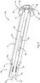
- Fig. 1 shows a spring brake actuator 2 having an actuator housing 4. Inside the actuator housing 4, an actuator power spring 6 and a pressure chamber 10 are located. The power spring 6, which rests on the left side in Fig. 1 against an actuator housing base 5 and on the opposite side on a spring brake actuator piston 8, is in Fig. 1 held in a released position by positive pressure inside the pressure chamber 10.
- the spring brake actuator piston 8 is adapted to transmit the inflicted force to a rod 11 which in turn transmits the applied power to the wheel brakes (not shown). Furthermore, the spring brake actuator 2 comprises a brake release mechanism 24. The brake release mechanism 24 is utilized to release the spring brake actuator 2.
- the brake release mechanism 24 comprises a brake release bolt 30 which is rotatably arranged within a release bolt housing 32.
- the brake release bolt 30 comprises a threaded portion 34 on which a running nut 12 is engaged.
- the release bolt housing 32 inhibits a rotatability of the running nut 12.
- the running nut 12 moves along the threaded portion 34 and thus axially along the release bolt 30.
- the running nut 12 is adapted to move the spring brake actuator piston 8 against a force of the actuator power spring 6. In other words, when the running nut 12 moves towards the actuator housing base 5, it forces the spring brake actuator piston 8 towards the actuator housing base 5, thereby compressing the actuator power spring 6. This, in consequence, releases the spring brake actuator 2.
- the brake release mechanism 24 furthermore comprises an indicator device 22.
- the indicator device 22 comprises an indicator pin 26 which is accommodated in a receiving space 36 of the release bolt 30.
- the indicator pin 26 is movable within the receiving space 36 relative to the brake release bolt 30.
- the indicator device 22 comprises a pin actuator 16 for moving the indicator pin 26 relative to the receiving space 36 along its longitudinal axis 28.
- the pin actuator 16 comprises a limiting element 40 which is connected to the indicator pin 26.
- the limiting element 40 extends substantially perpendicular to the longitudinal axis 28 of the indicator pin 26.
- the spring brake actuator 2 moreover comprises an internal breathing valve 14.
- Fig. 2 shows a first embodiment of the brake release mechanism 24 comprising a brake release bolt 30.
- the brake release bolt 30 comprises the threaded portion 34 on which the running nut 12 is able to move axially along the brake release bolt 30.
- the pin actuator 38 comprises the limiting element 40 being connectable to the indicator pin 26.
- the release bolt 30 comprises a transverse guide opening 42 for loosely accommodating the limiting element 40 and limiting a motion distance d of the indicator pin 26 along the longitudinal axis 28.
- the transverse guide opening 42 is arranged perpendicular to the longitudinal axis 28 of the indicator pin 26.
- the transverse guide opening 42 extends entirely through the release bolt 30.
- the transverse guide opening 42 is arranged partially at the threaded portion 34 of the release bolt 30.
- the limiting element 40 comprises a pin 38.
- the brake release bolt 30 furthermore comprises a spring element 20 forcing the indicator pin 26 in a first direction 46 along the longitudinal axis 28 towards the operating section 18.
- the limiting element 40 is configured to indirectly abut against the running nut 12 for moving the indicator pin 26 against a force of the spring element 20 in a second direction 48.
- the second direction 48 is opposite to the first direction 46.
- a spacing means 50 is arranged between the running nut 12 and the limiting element 40.
- the spacing means 50 decouples the limiting element 40 from the torque applied by the running nut 12.
- the spacing means 50 is configured as a plain washer 52.
- the brake release bolt 30 furthermore comprises a sealing 54 and a fitting piece 56 for fitting the brake release bolt 30 into the release bolt receiving space 36.
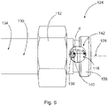
- Fig. 3 and Fig. 4 show an alternative embodiment of the brake release mechanism 124.
- the brake release mechanism 124 comprises a brake release bolt 130 having a threaded portion 134 and an operating section 118 for operating the release bolt 130 when inserted into a spring brake actuator 2 (see Fig. 1 ).
- a running nut 112 engages the threaded portion 134.
- the running nut 112 is adapted to axially travel along the threaded portion 134.
- the brake release mechanism 124 moreover comprises an indicator device 122 comprising an indicator pin 126.
- the indicator pin 126 has a longitudinal axis 128 and is at least partially accommodated in a receiving space 136 of the release bolt 130.
- the indicator device 122 further comprises a pin actuator 116 for moving the indicator pin 126 relative to the receiving space 136 along its longitudinal axis 128.
- the pin actuator 138 comprises a limiting element 140 which is connected to the indicator pin 126.
- the limiting element 140 extends perpendicular to the longitudinal axis 128 of the indicator pin 126.
- the brake release bolt 130 comprises a transverse guide opening 142 for loosely accommodating the limiting element 140 and limiting a motion distance d of the indicator pin 126 along the longitudinal axis 128.
- the transverse guide opening 142 is arranged perpendicular to the longitudinal axis 128 of the indicator pin 126, wherein the transverse guide opening 142 extends entirely through the release bolt 130.
- the transverse guide opening 142 is partially arranged at the threaded portion 134 of the release bolt 130.
- the limiting element 140 is configured as a pin 138, wherein the pin 138 is made of steel.
- the opening 142 is of a cylindrical shape 160.
- the brake release bolt 130 comprises an end portion 158 which is arranged on the opposite side of the operating section 118 at the brake release bolt 130.
- the brake release bolt 130 comprises a sealing 154 and a fitting piece 156 for fitting the brake release bolt 130 relative to a release bolt housing 32 (see Fig. 1 ).
- the embodiment of Figs. 3 to 5 does not comprise a spacing means 50. Rather, the running nut 112 directly abuts against the limiting element 140. As can be seen from Fig. 5 , the geometry of the transverse guide opening 142 limits the motion distance d of the pin 138. In the state shown in Fig. 5 , the pin 138 is forced towards a left boundary (in the orientation of Fig. 5 ) of the transverse guide opening 142 by a spring element (not shown, see Figs. 1 and 2 ). When the running nut 112 travels towards the right side of Fig.
Landscapes
- Engineering & Computer Science (AREA)
- Transportation (AREA)
- Mechanical Engineering (AREA)
- Braking Arrangements (AREA)
Priority Applications (1)
| Application Number | Priority Date | Filing Date | Title |
|---|---|---|---|
| EP20209724.2A EP4005884B1 (de) | 2020-11-25 | 2020-11-25 | Bremslösungsmechanismus für einen federspeicherbremszylinder und zugehöriger federspeicherbremszylinder |
Applications Claiming Priority (1)
| Application Number | Priority Date | Filing Date | Title |
|---|---|---|---|
| EP20209724.2A EP4005884B1 (de) | 2020-11-25 | 2020-11-25 | Bremslösungsmechanismus für einen federspeicherbremszylinder und zugehöriger federspeicherbremszylinder |
Publications (2)
| Publication Number | Publication Date |
|---|---|
| EP4005884A1 true EP4005884A1 (de) | 2022-06-01 |
| EP4005884B1 EP4005884B1 (de) | 2023-08-16 |
Family
ID=73597889
Family Applications (1)
| Application Number | Title | Priority Date | Filing Date |
|---|---|---|---|
| EP20209724.2A Active EP4005884B1 (de) | 2020-11-25 | 2020-11-25 | Bremslösungsmechanismus für einen federspeicherbremszylinder und zugehöriger federspeicherbremszylinder |
Country Status (1)
| Country | Link |
|---|---|
| EP (1) | EP4005884B1 (de) |
Citations (5)
| Publication number | Priority date | Publication date | Assignee | Title |
|---|---|---|---|---|
| EP0530461A1 (de) * | 1991-09-02 | 1993-03-10 | WABCO STANDARD GmbH | Einrichtung zur Axialverschiebung eines Bauteils |
| US5632192A (en) * | 1995-12-19 | 1997-05-27 | Indian Head Industries, Inc. | Spring brake actuator with indicator for fully released condition |
| US5636562A (en) * | 1995-08-15 | 1997-06-10 | Indian Head Industries, Inc. | Spring brake actuator with release tool requiring limited axial space |
| US5943940A (en) * | 1995-11-30 | 1999-08-31 | Ab Volvo | Indication means in a brake cylinder for a vehicle brake |
| EP3498550A1 (de) * | 2017-12-13 | 2019-06-19 | WABCO Europe BVBA | Federabschnitt eines federspeicherbremsaktuators, federspeicherbremsaktuator und fahrzeug damit |
-
2020
- 2020-11-25 EP EP20209724.2A patent/EP4005884B1/de active Active
Patent Citations (5)
| Publication number | Priority date | Publication date | Assignee | Title |
|---|---|---|---|---|
| EP0530461A1 (de) * | 1991-09-02 | 1993-03-10 | WABCO STANDARD GmbH | Einrichtung zur Axialverschiebung eines Bauteils |
| US5636562A (en) * | 1995-08-15 | 1997-06-10 | Indian Head Industries, Inc. | Spring brake actuator with release tool requiring limited axial space |
| US5943940A (en) * | 1995-11-30 | 1999-08-31 | Ab Volvo | Indication means in a brake cylinder for a vehicle brake |
| US5632192A (en) * | 1995-12-19 | 1997-05-27 | Indian Head Industries, Inc. | Spring brake actuator with indicator for fully released condition |
| EP3498550A1 (de) * | 2017-12-13 | 2019-06-19 | WABCO Europe BVBA | Federabschnitt eines federspeicherbremsaktuators, federspeicherbremsaktuator und fahrzeug damit |
Also Published As
| Publication number | Publication date |
|---|---|
| EP4005884B1 (de) | 2023-08-16 |
Similar Documents
| Publication | Publication Date | Title |
|---|---|---|
| CN107084242B (zh) | 锁止装置 | |
| KR102516419B1 (ko) | 전기 기계식 브레이크 부스터 및 브레이크 시스템 | |
| CA2575305C (en) | Adjusting device for a pneumatic disc brake | |
| EP2932131B1 (de) | Scheibenbremse mit einer feststellbremse, mechanische schubvorrichtung und verfahren zur montage | |
| CN101918257A (zh) | 带有能够通过制动踏板接通的耦联件且用于将驱动装置从活塞-缸-单元脱离的制动装置 | |
| CN110741187A (zh) | 用于机动车中的自动变速器的驻车锁止器 | |
| US20060283683A1 (en) | Clutch actuator | |
| US11041551B2 (en) | Pivotable spindle nut | |
| DE102015008709A1 (de) | Parksperrenmodul | |
| US20170009832A1 (en) | Drum brake module which can be operated by electric motor | |
| EP4005884B1 (de) | Bremslösungsmechanismus für einen federspeicherbremszylinder und zugehöriger federspeicherbremszylinder | |
| US20060065778A1 (en) | Actuator with helical cam guides | |
| US11565679B2 (en) | Spring brake actuator and brake release mechanism therefor | |
| CN113677574B (zh) | 用于制动装备的操纵装置 | |
| EP3483480B1 (de) | Hydraulische steuerungsvorrichtung für ein fahrzeug | |
| EP3953226B1 (de) | Federspeicherbremse, bremssystem, fahrzeug | |
| EP3964411B1 (de) | Bremslösemechanismus für einen federspeicherbremszylinder und federspeicherbremszylinder mit solch einem bremslösemechanismus | |
| EP4350165A1 (de) | Feststellbremsaktuator | |
| EP4385841B1 (de) | Elektromechanische aktuatoranordnung zur betätigung eines bremsaktuators, bremsanordnung und fahrzeug | |
| JP2609455B2 (ja) | 乗物用油圧式ディスクブレーキの機械的手動制御装置 | |
| US20250001991A1 (en) | Actuation device for a brake system | |
| EP4069562B1 (de) | Bremsaktuator, insbesondere elektromechanischer bremsaktuator für ein nutzfahrzeug | |
| EP4386232A1 (de) | Elektromechanische aktuatoranordnung zur betätigung eines bremsaktuators, bremsanordnung und fahrzeug | |
| US10940846B2 (en) | Electromechanical brake assist system | |
| CN120963636A (zh) | 具有紧凑的旋转-平移转换器的电子机械式制动设备 |
Legal Events
| Date | Code | Title | Description |
|---|---|---|---|
| PUAI | Public reference made under article 153(3) epc to a published international application that has entered the european phase |
Free format text: ORIGINAL CODE: 0009012 |
|
| STAA | Information on the status of an ep patent application or granted ep patent |
Free format text: STATUS: THE APPLICATION HAS BEEN PUBLISHED |
|
| AK | Designated contracting states |
Kind code of ref document: A1 Designated state(s): AL AT BE BG CH CY CZ DE DK EE ES FI FR GB GR HR HU IE IS IT LI LT LU LV MC MK MT NL NO PL PT RO RS SE SI SK SM TR |
|
| STAA | Information on the status of an ep patent application or granted ep patent |
Free format text: STATUS: REQUEST FOR EXAMINATION WAS MADE |
|
| 17P | Request for examination filed |
Effective date: 20221201 |
|
| RBV | Designated contracting states (corrected) |
Designated state(s): AL AT BE BG CH CY CZ DE DK EE ES FI FR GB GR HR HU IE IS IT LI LT LU LV MC MK MT NL NO PL PT RO RS SE SI SK SM TR |
|
| GRAP | Despatch of communication of intention to grant a patent |
Free format text: ORIGINAL CODE: EPIDOSNIGR1 |
|
| STAA | Information on the status of an ep patent application or granted ep patent |
Free format text: STATUS: GRANT OF PATENT IS INTENDED |
|
| RIC1 | Information provided on ipc code assigned before grant |
Ipc: B60T 17/08 20060101AFI20230428BHEP |
|
| INTG | Intention to grant announced |
Effective date: 20230522 |
|
| GRAS | Grant fee paid |
Free format text: ORIGINAL CODE: EPIDOSNIGR3 |
|
| GRAA | (expected) grant |
Free format text: ORIGINAL CODE: 0009210 |
|
| STAA | Information on the status of an ep patent application or granted ep patent |
Free format text: STATUS: THE PATENT HAS BEEN GRANTED |
|
| AK | Designated contracting states |
Kind code of ref document: B1 Designated state(s): AL AT BE BG CH CY CZ DE DK EE ES FI FR GB GR HR HU IE IS IT LI LT LU LV MC MK MT NL NO PL PT RO RS SE SI SK SM TR |
|
| REG | Reference to a national code |
Ref country code: CH Ref legal event code: EP Ref country code: DE Ref legal event code: R096 Ref document number: 602020015773 Country of ref document: DE |
|
| REG | Reference to a national code |
Ref country code: IE Ref legal event code: FG4D |
|
| REG | Reference to a national code |
Ref country code: LT Ref legal event code: MG9D |
|
| REG | Reference to a national code |
Ref country code: NL Ref legal event code: MP Effective date: 20230816 |
|
| REG | Reference to a national code |
Ref country code: AT Ref legal event code: MK05 Ref document number: 1599769 Country of ref document: AT Kind code of ref document: T Effective date: 20230816 |
|
| PG25 | Lapsed in a contracting state [announced via postgrant information from national office to epo] |
Ref country code: GR Free format text: LAPSE BECAUSE OF FAILURE TO SUBMIT A TRANSLATION OF THE DESCRIPTION OR TO PAY THE FEE WITHIN THE PRESCRIBED TIME-LIMIT Effective date: 20231117 |
|
| PG25 | Lapsed in a contracting state [announced via postgrant information from national office to epo] |
Ref country code: IS Free format text: LAPSE BECAUSE OF FAILURE TO SUBMIT A TRANSLATION OF THE DESCRIPTION OR TO PAY THE FEE WITHIN THE PRESCRIBED TIME-LIMIT Effective date: 20231216 |
|
| PG25 | Lapsed in a contracting state [announced via postgrant information from national office to epo] |
Ref country code: SE Free format text: LAPSE BECAUSE OF FAILURE TO SUBMIT A TRANSLATION OF THE DESCRIPTION OR TO PAY THE FEE WITHIN THE PRESCRIBED TIME-LIMIT Effective date: 20230816 Ref country code: RS Free format text: LAPSE BECAUSE OF FAILURE TO SUBMIT A TRANSLATION OF THE DESCRIPTION OR TO PAY THE FEE WITHIN THE PRESCRIBED TIME-LIMIT Effective date: 20230816 Ref country code: PT Free format text: LAPSE BECAUSE OF FAILURE TO SUBMIT A TRANSLATION OF THE DESCRIPTION OR TO PAY THE FEE WITHIN THE PRESCRIBED TIME-LIMIT Effective date: 20231218 Ref country code: NO Free format text: LAPSE BECAUSE OF FAILURE TO SUBMIT A TRANSLATION OF THE DESCRIPTION OR TO PAY THE FEE WITHIN THE PRESCRIBED TIME-LIMIT Effective date: 20231116 Ref country code: NL Free format text: LAPSE BECAUSE OF FAILURE TO SUBMIT A TRANSLATION OF THE DESCRIPTION OR TO PAY THE FEE WITHIN THE PRESCRIBED TIME-LIMIT Effective date: 20230816 Ref country code: LV Free format text: LAPSE BECAUSE OF FAILURE TO SUBMIT A TRANSLATION OF THE DESCRIPTION OR TO PAY THE FEE WITHIN THE PRESCRIBED TIME-LIMIT Effective date: 20230816 Ref country code: LT Free format text: LAPSE BECAUSE OF FAILURE TO SUBMIT A TRANSLATION OF THE DESCRIPTION OR TO PAY THE FEE WITHIN THE PRESCRIBED TIME-LIMIT Effective date: 20230816 Ref country code: IS Free format text: LAPSE BECAUSE OF FAILURE TO SUBMIT A TRANSLATION OF THE DESCRIPTION OR TO PAY THE FEE WITHIN THE PRESCRIBED TIME-LIMIT Effective date: 20231216 Ref country code: HR Free format text: LAPSE BECAUSE OF FAILURE TO SUBMIT A TRANSLATION OF THE DESCRIPTION OR TO PAY THE FEE WITHIN THE PRESCRIBED TIME-LIMIT Effective date: 20230816 Ref country code: GR Free format text: LAPSE BECAUSE OF FAILURE TO SUBMIT A TRANSLATION OF THE DESCRIPTION OR TO PAY THE FEE WITHIN THE PRESCRIBED TIME-LIMIT Effective date: 20231117 Ref country code: FI Free format text: LAPSE BECAUSE OF FAILURE TO SUBMIT A TRANSLATION OF THE DESCRIPTION OR TO PAY THE FEE WITHIN THE PRESCRIBED TIME-LIMIT Effective date: 20230816 Ref country code: AT Free format text: LAPSE BECAUSE OF FAILURE TO SUBMIT A TRANSLATION OF THE DESCRIPTION OR TO PAY THE FEE WITHIN THE PRESCRIBED TIME-LIMIT Effective date: 20230816 |
|
| PG25 | Lapsed in a contracting state [announced via postgrant information from national office to epo] |
Ref country code: PL Free format text: LAPSE BECAUSE OF FAILURE TO SUBMIT A TRANSLATION OF THE DESCRIPTION OR TO PAY THE FEE WITHIN THE PRESCRIBED TIME-LIMIT Effective date: 20230816 |
|
| PG25 | Lapsed in a contracting state [announced via postgrant information from national office to epo] |
Ref country code: ES Free format text: LAPSE BECAUSE OF FAILURE TO SUBMIT A TRANSLATION OF THE DESCRIPTION OR TO PAY THE FEE WITHIN THE PRESCRIBED TIME-LIMIT Effective date: 20230816 |
|
| PG25 | Lapsed in a contracting state [announced via postgrant information from national office to epo] |
Ref country code: SM Free format text: LAPSE BECAUSE OF FAILURE TO SUBMIT A TRANSLATION OF THE DESCRIPTION OR TO PAY THE FEE WITHIN THE PRESCRIBED TIME-LIMIT Effective date: 20230816 Ref country code: RO Free format text: LAPSE BECAUSE OF FAILURE TO SUBMIT A TRANSLATION OF THE DESCRIPTION OR TO PAY THE FEE WITHIN THE PRESCRIBED TIME-LIMIT Effective date: 20230816 Ref country code: ES Free format text: LAPSE BECAUSE OF FAILURE TO SUBMIT A TRANSLATION OF THE DESCRIPTION OR TO PAY THE FEE WITHIN THE PRESCRIBED TIME-LIMIT Effective date: 20230816 Ref country code: EE Free format text: LAPSE BECAUSE OF FAILURE TO SUBMIT A TRANSLATION OF THE DESCRIPTION OR TO PAY THE FEE WITHIN THE PRESCRIBED TIME-LIMIT Effective date: 20230816 Ref country code: DK Free format text: LAPSE BECAUSE OF FAILURE TO SUBMIT A TRANSLATION OF THE DESCRIPTION OR TO PAY THE FEE WITHIN THE PRESCRIBED TIME-LIMIT Effective date: 20230816 Ref country code: CZ Free format text: LAPSE BECAUSE OF FAILURE TO SUBMIT A TRANSLATION OF THE DESCRIPTION OR TO PAY THE FEE WITHIN THE PRESCRIBED TIME-LIMIT Effective date: 20230816 Ref country code: SK Free format text: LAPSE BECAUSE OF FAILURE TO SUBMIT A TRANSLATION OF THE DESCRIPTION OR TO PAY THE FEE WITHIN THE PRESCRIBED TIME-LIMIT Effective date: 20230816 |
|
| REG | Reference to a national code |
Ref country code: DE Ref legal event code: R097 Ref document number: 602020015773 Country of ref document: DE |
|
| PLBE | No opposition filed within time limit |
Free format text: ORIGINAL CODE: 0009261 |
|
| STAA | Information on the status of an ep patent application or granted ep patent |
Free format text: STATUS: NO OPPOSITION FILED WITHIN TIME LIMIT |
|
| REG | Reference to a national code |
Ref country code: CH Ref legal event code: PL |
|
| PG25 | Lapsed in a contracting state [announced via postgrant information from national office to epo] |
Ref country code: MC Free format text: LAPSE BECAUSE OF FAILURE TO SUBMIT A TRANSLATION OF THE DESCRIPTION OR TO PAY THE FEE WITHIN THE PRESCRIBED TIME-LIMIT Effective date: 20230816 |
|
| PG25 | Lapsed in a contracting state [announced via postgrant information from national office to epo] |
Ref country code: LU Free format text: LAPSE BECAUSE OF NON-PAYMENT OF DUE FEES Effective date: 20231125 |
|
| PG25 | Lapsed in a contracting state [announced via postgrant information from national office to epo] |
Ref country code: CH Free format text: LAPSE BECAUSE OF NON-PAYMENT OF DUE FEES Effective date: 20231130 |
|
| 26N | No opposition filed |
Effective date: 20240517 |
|
| PG25 | Lapsed in a contracting state [announced via postgrant information from national office to epo] |
Ref country code: MC Free format text: LAPSE BECAUSE OF FAILURE TO SUBMIT A TRANSLATION OF THE DESCRIPTION OR TO PAY THE FEE WITHIN THE PRESCRIBED TIME-LIMIT Effective date: 20230816 Ref country code: LU Free format text: LAPSE BECAUSE OF NON-PAYMENT OF DUE FEES Effective date: 20231125 Ref country code: IT Free format text: LAPSE BECAUSE OF FAILURE TO SUBMIT A TRANSLATION OF THE DESCRIPTION OR TO PAY THE FEE WITHIN THE PRESCRIBED TIME-LIMIT Effective date: 20230816 Ref country code: CH Free format text: LAPSE BECAUSE OF NON-PAYMENT OF DUE FEES Effective date: 20231130 Ref country code: SI Free format text: LAPSE BECAUSE OF FAILURE TO SUBMIT A TRANSLATION OF THE DESCRIPTION OR TO PAY THE FEE WITHIN THE PRESCRIBED TIME-LIMIT Effective date: 20230816 |
|
| REG | Reference to a national code |
Ref country code: BE Ref legal event code: MM Effective date: 20231130 |
|
| REG | Reference to a national code |
Ref country code: IE Ref legal event code: MM4A |
|
| PG25 | Lapsed in a contracting state [announced via postgrant information from national office to epo] |
Ref country code: IE Free format text: LAPSE BECAUSE OF NON-PAYMENT OF DUE FEES Effective date: 20231125 |
|
| PG25 | Lapsed in a contracting state [announced via postgrant information from national office to epo] |
Ref country code: BE Free format text: LAPSE BECAUSE OF NON-PAYMENT OF DUE FEES Effective date: 20231130 |
|
| PG25 | Lapsed in a contracting state [announced via postgrant information from national office to epo] |
Ref country code: IE Free format text: LAPSE BECAUSE OF NON-PAYMENT OF DUE FEES Effective date: 20231125 Ref country code: BE Free format text: LAPSE BECAUSE OF NON-PAYMENT OF DUE FEES Effective date: 20231130 |
|
| PG25 | Lapsed in a contracting state [announced via postgrant information from national office to epo] |
Ref country code: BG Free format text: LAPSE BECAUSE OF FAILURE TO SUBMIT A TRANSLATION OF THE DESCRIPTION OR TO PAY THE FEE WITHIN THE PRESCRIBED TIME-LIMIT Effective date: 20230816 |
|
| PG25 | Lapsed in a contracting state [announced via postgrant information from national office to epo] |
Ref country code: BG Free format text: LAPSE BECAUSE OF FAILURE TO SUBMIT A TRANSLATION OF THE DESCRIPTION OR TO PAY THE FEE WITHIN THE PRESCRIBED TIME-LIMIT Effective date: 20230816 |
|
| PGFP | Annual fee paid to national office [announced via postgrant information from national office to epo] |
Ref country code: DE Payment date: 20241001 Year of fee payment: 5 |
|
| PGFP | Annual fee paid to national office [announced via postgrant information from national office to epo] |
Ref country code: GB Payment date: 20241001 Year of fee payment: 5 |
|
| PG25 | Lapsed in a contracting state [announced via postgrant information from national office to epo] |
Ref country code: CY Free format text: LAPSE BECAUSE OF FAILURE TO SUBMIT A TRANSLATION OF THE DESCRIPTION OR TO PAY THE FEE WITHIN THE PRESCRIBED TIME-LIMIT; INVALID AB INITIO Effective date: 20201125 |
|
| PG25 | Lapsed in a contracting state [announced via postgrant information from national office to epo] |
Ref country code: HU Free format text: LAPSE BECAUSE OF FAILURE TO SUBMIT A TRANSLATION OF THE DESCRIPTION OR TO PAY THE FEE WITHIN THE PRESCRIBED TIME-LIMIT; INVALID AB INITIO Effective date: 20201125 |
|
| PGFP | Annual fee paid to national office [announced via postgrant information from national office to epo] |
Ref country code: FR Payment date: 20250930 Year of fee payment: 6 |