EP4005687A1 - Coating device and coating method - Google Patents
Coating device and coating method Download PDFInfo
- Publication number
- EP4005687A1 EP4005687A1 EP20847795.0A EP20847795A EP4005687A1 EP 4005687 A1 EP4005687 A1 EP 4005687A1 EP 20847795 A EP20847795 A EP 20847795A EP 4005687 A1 EP4005687 A1 EP 4005687A1
- Authority
- EP
- European Patent Office
- Prior art keywords
- head
- coating
- nozzle surface
- coating device
- discharge
- Prior art date
- Legal status (The legal status is an assumption and is not a legal conclusion. Google has not performed a legal analysis and makes no representation as to the accuracy of the status listed.)
- Granted
Links
Images









Classifications
-
- B—PERFORMING OPERATIONS; TRANSPORTING
- B05—SPRAYING OR ATOMISING IN GENERAL; APPLYING FLUENT MATERIALS TO SURFACES, IN GENERAL
- B05C—APPARATUS FOR APPLYING FLUENT MATERIALS TO SURFACES, IN GENERAL
- B05C5/00—Apparatus in which liquid or other fluent material is projected, poured or allowed to flow on to the surface of the work
- B05C5/02—Apparatus in which liquid or other fluent material is projected, poured or allowed to flow on to the surface of the work the liquid or other fluent material being discharged through an outlet orifice by pressure, e.g. from an outlet device in contact or almost in contact, with the work
-
- B—PERFORMING OPERATIONS; TRANSPORTING
- B05—SPRAYING OR ATOMISING IN GENERAL; APPLYING FLUENT MATERIALS TO SURFACES, IN GENERAL
- B05B—SPRAYING APPARATUS; ATOMISING APPARATUS; NOZZLES
- B05B1/00—Nozzles, spray heads or other outlets, with or without auxiliary devices such as valves, heating means
- B05B1/14—Nozzles, spray heads or other outlets, with or without auxiliary devices such as valves, heating means with multiple outlet openings; with strainers in or outside the outlet opening
-
- B—PERFORMING OPERATIONS; TRANSPORTING
- B05—SPRAYING OR ATOMISING IN GENERAL; APPLYING FLUENT MATERIALS TO SURFACES, IN GENERAL
- B05B—SPRAYING APPARATUS; ATOMISING APPARATUS; NOZZLES
- B05B13/00—Machines or plants for applying liquids or other fluent materials to surfaces of objects or other work by spraying, not covered by groups B05B1/00 - B05B11/00
- B05B13/002—Machines or plants for applying coating liquids or other fluent materials by inkjet
-
- B—PERFORMING OPERATIONS; TRANSPORTING
- B05—SPRAYING OR ATOMISING IN GENERAL; APPLYING FLUENT MATERIALS TO SURFACES, IN GENERAL
- B05B—SPRAYING APPARATUS; ATOMISING APPARATUS; NOZZLES
- B05B13/00—Machines or plants for applying liquids or other fluent materials to surfaces of objects or other work by spraying, not covered by groups B05B1/00 - B05B11/00
- B05B13/02—Means for supporting work; Arrangement or mounting of spray heads; Adaptation or arrangement of means for feeding work
- B05B13/04—Means for supporting work; Arrangement or mounting of spray heads; Adaptation or arrangement of means for feeding work the spray heads being moved during spraying operation
- B05B13/0405—Means for supporting work; Arrangement or mounting of spray heads; Adaptation or arrangement of means for feeding work the spray heads being moved during spraying operation with reciprocating or oscillating spray heads
-
- B—PERFORMING OPERATIONS; TRANSPORTING
- B05—SPRAYING OR ATOMISING IN GENERAL; APPLYING FLUENT MATERIALS TO SURFACES, IN GENERAL
- B05B—SPRAYING APPARATUS; ATOMISING APPARATUS; NOZZLES
- B05B13/00—Machines or plants for applying liquids or other fluent materials to surfaces of objects or other work by spraying, not covered by groups B05B1/00 - B05B11/00
- B05B13/02—Means for supporting work; Arrangement or mounting of spray heads; Adaptation or arrangement of means for feeding work
- B05B13/04—Means for supporting work; Arrangement or mounting of spray heads; Adaptation or arrangement of means for feeding work the spray heads being moved during spraying operation
- B05B13/0405—Means for supporting work; Arrangement or mounting of spray heads; Adaptation or arrangement of means for feeding work the spray heads being moved during spraying operation with reciprocating or oscillating spray heads
- B05B13/041—Means for supporting work; Arrangement or mounting of spray heads; Adaptation or arrangement of means for feeding work the spray heads being moved during spraying operation with reciprocating or oscillating spray heads with spray heads reciprocating along a straight line
- B05B13/0415—Means for supporting work; Arrangement or mounting of spray heads; Adaptation or arrangement of means for feeding work the spray heads being moved during spraying operation with reciprocating or oscillating spray heads with spray heads reciprocating along a straight line the angular position of the spray heads relative to the straight line being modified during the reciprocating movement
-
- B—PERFORMING OPERATIONS; TRANSPORTING
- B05—SPRAYING OR ATOMISING IN GENERAL; APPLYING FLUENT MATERIALS TO SURFACES, IN GENERAL
- B05B—SPRAYING APPARATUS; ATOMISING APPARATUS; NOZZLES
- B05B13/00—Machines or plants for applying liquids or other fluent materials to surfaces of objects or other work by spraying, not covered by groups B05B1/00 - B05B11/00
- B05B13/02—Means for supporting work; Arrangement or mounting of spray heads; Adaptation or arrangement of means for feeding work
- B05B13/04—Means for supporting work; Arrangement or mounting of spray heads; Adaptation or arrangement of means for feeding work the spray heads being moved during spraying operation
- B05B13/0431—Means for supporting work; Arrangement or mounting of spray heads; Adaptation or arrangement of means for feeding work the spray heads being moved during spraying operation with spray heads moved by robots or articulated arms, e.g. for applying liquid or other fluent material to three-dimensional [3D] surfaces
- B05B13/0433—Means for supporting work; Arrangement or mounting of spray heads; Adaptation or arrangement of means for feeding work the spray heads being moved during spraying operation with spray heads moved by robots or articulated arms, e.g. for applying liquid or other fluent material to three-dimensional [3D] surfaces the work being vehicle components, e.g. vehicle bodies
-
- B—PERFORMING OPERATIONS; TRANSPORTING
- B05—SPRAYING OR ATOMISING IN GENERAL; APPLYING FLUENT MATERIALS TO SURFACES, IN GENERAL
- B05B—SPRAYING APPARATUS; ATOMISING APPARATUS; NOZZLES
- B05B15/00—Details of spraying plant or spraying apparatus not otherwise provided for; Accessories
- B05B15/50—Arrangements for cleaning; Arrangements for preventing deposits, drying-out or blockage; Arrangements for detecting improper discharge caused by the presence of foreign matter
-
- B—PERFORMING OPERATIONS; TRANSPORTING
- B05—SPRAYING OR ATOMISING IN GENERAL; APPLYING FLUENT MATERIALS TO SURFACES, IN GENERAL
- B05B—SPRAYING APPARATUS; ATOMISING APPARATUS; NOZZLES
- B05B15/00—Details of spraying plant or spraying apparatus not otherwise provided for; Accessories
- B05B15/60—Arrangements for mounting, supporting or holding spraying apparatus
- B05B15/68—Arrangements for adjusting the position of spray heads
-
- B—PERFORMING OPERATIONS; TRANSPORTING
- B05—SPRAYING OR ATOMISING IN GENERAL; APPLYING FLUENT MATERIALS TO SURFACES, IN GENERAL
- B05B—SPRAYING APPARATUS; ATOMISING APPARATUS; NOZZLES
- B05B3/00—Spraying or sprinkling apparatus with moving outlet elements or moving deflecting elements
- B05B3/02—Spraying or sprinkling apparatus with moving outlet elements or moving deflecting elements with rotating elements
-
- B—PERFORMING OPERATIONS; TRANSPORTING
- B05—SPRAYING OR ATOMISING IN GENERAL; APPLYING FLUENT MATERIALS TO SURFACES, IN GENERAL
- B05B—SPRAYING APPARATUS; ATOMISING APPARATUS; NOZZLES
- B05B3/00—Spraying or sprinkling apparatus with moving outlet elements or moving deflecting elements
- B05B3/14—Spraying or sprinkling apparatus with moving outlet elements or moving deflecting elements with oscillating elements; with intermittent operation
-
- B—PERFORMING OPERATIONS; TRANSPORTING
- B05—SPRAYING OR ATOMISING IN GENERAL; APPLYING FLUENT MATERIALS TO SURFACES, IN GENERAL
- B05D—PROCESSES FOR APPLYING FLUENT MATERIALS TO SURFACES, IN GENERAL
- B05D1/00—Processes for applying liquids or other fluent materials
- B05D1/26—Processes for applying liquids or other fluent materials performed by applying the liquid or other fluent material from an outlet device in contact with, or almost in contact with, the surface
-
- B—PERFORMING OPERATIONS; TRANSPORTING
- B25—HAND TOOLS; PORTABLE POWER-DRIVEN TOOLS; MANIPULATORS
- B25J—MANIPULATORS; CHAMBERS PROVIDED WITH MANIPULATION DEVICES
- B25J9/00—Program-controlled manipulators
- B25J9/16—Program controls
- B25J9/1679—Program controls characterised by the tasks executed
-
- B—PERFORMING OPERATIONS; TRANSPORTING
- B41—PRINTING; LINING MACHINES; TYPEWRITERS; STAMPS
- B41J—TYPEWRITERS; SELECTIVE PRINTING MECHANISMS, i.e. MECHANISMS PRINTING OTHERWISE THAN FROM A FORME; CORRECTION OF TYPOGRAPHICAL ERRORS
- B41J25/00—Actions or mechanisms not otherwise provided for
- B41J25/001—Mechanisms for bodily moving print heads or carriages parallel to the paper surface
-
- B—PERFORMING OPERATIONS; TRANSPORTING
- B41—PRINTING; LINING MACHINES; TYPEWRITERS; STAMPS
- B41J—TYPEWRITERS; SELECTIVE PRINTING MECHANISMS, i.e. MECHANISMS PRINTING OTHERWISE THAN FROM A FORME; CORRECTION OF TYPOGRAPHICAL ERRORS
- B41J25/00—Actions or mechanisms not otherwise provided for
- B41J25/001—Mechanisms for bodily moving print heads or carriages parallel to the paper surface
- B41J25/006—Mechanisms for bodily moving print heads or carriages parallel to the paper surface for oscillating, e.g. page-width print heads provided with counter-balancing means or shock absorbers
-
- B—PERFORMING OPERATIONS; TRANSPORTING
- B05—SPRAYING OR ATOMISING IN GENERAL; APPLYING FLUENT MATERIALS TO SURFACES, IN GENERAL
- B05D—PROCESSES FOR APPLYING FLUENT MATERIALS TO SURFACES, IN GENERAL
- B05D7/00—Processes, other than flocking, specially adapted for applying liquids or other fluent materials to particular surfaces or for applying particular liquids or other fluent materials
- B05D7/14—Processes, other than flocking, specially adapted for applying liquids or other fluent materials to particular surfaces or for applying particular liquids or other fluent materials to metal, e.g. car bodies
-
- B—PERFORMING OPERATIONS; TRANSPORTING
- B05—SPRAYING OR ATOMISING IN GENERAL; APPLYING FLUENT MATERIALS TO SURFACES, IN GENERAL
- B05D—PROCESSES FOR APPLYING FLUENT MATERIALS TO SURFACES, IN GENERAL
- B05D7/00—Processes, other than flocking, specially adapted for applying liquids or other fluent materials to particular surfaces or for applying particular liquids or other fluent materials
- B05D7/50—Multilayers
- B05D7/56—Three layers or more
-
- G—PHYSICS
- G05—CONTROLLING; REGULATING
- G05B—CONTROL OR REGULATING SYSTEMS IN GENERAL; FUNCTIONAL ELEMENTS OF SUCH SYSTEMS; MONITORING OR TESTING ARRANGEMENTS FOR SUCH SYSTEMS OR ELEMENTS
- G05B2219/00—Program-control systems
- G05B2219/30—Nc systems
- G05B2219/45—Nc applications
- G05B2219/45013—Spraying, coating, painting
Definitions
- Disclosed embodiments relate to a coating device and a coating method.
- a coating device using an inkjet method is known.
- a head for discharging a coating material is mounted on such a coating device of an inkjet method.
- a coating device includes a head, an arm, and a controller.
- the head includes a nozzle surface.
- the arm holds the head.
- the controller controls movement of the head via the arm.
- the controller vibrates the head in a second direction intersecting a first direction, and/or rotationally oscillates the head along the nozzle surface while moving the head in the first direction along the nozzle surface in a state where the nozzle surface and a to-be-coated object face each other.
- FIG. 1 is an explanatory view of the coating device according to the embodiment.
- a coating device 1 includes a head 10, a robot 20, and a control device 40.
- the head 10 is fixed to the robot 20.
- the head 10 moves in response to movement of the robot 20 controlled by the control device 40.
- the head 10 can use, for example, an inkjet head of a valve type, a piezo type, or a thermal type.
- an inkjet head of a valve type, a piezo type, or a thermal type When a piezo type or thermal type inkjet head is used as the head 10, high resolution is easily realized.
- the head 10 coats a to-be-coated object 30 by depositing a coating material discharged from a plurality of discharge holes 11 located on a nozzle surface 12 onto a surface of the to-be-coated object 30 facing the nozzle surface 12.
- the coating material is supplied to the head 10 from a tank (not illustrated).
- the head 10 discharges the coating material supplied from the tank.
- the coating material is a mixture containing a volatile component and a nonvolatile component, and has fluidity.
- the tank may be a reservoir (not illustrated) housed in the head 10.
- the volatile component is, for example, water, organic solvent, or alcohol, and adjusts the physical properties such as viscosity and surface tension of the coating material.
- the nonvolatile component contains, for example, a pigment, a resin material, and an additive.
- the pigment includes one or more colored pigments used depending on a desired coating color.
- the resin material is deposited on the to-be-coated object 30 and forms a film.
- the additive is a functional material that is added, for example for purposes of weather resistance and the like.
- the coating material supplied to the discharge holes 11 is prepared such that a desired coating color is expressed by mixing a plurality of colored pigments or coating materials at predetermined proportions.
- the robot 20 holds the head 10.
- the robot 20 is, for example, a six-axis articulated robot.
- the robot 20 may be, for example, a vertical articulated robot or a horizontal articulated robot.
- the robot 20 includes a plurality of arms 21 with the head 10 fixed to a tip of the plurality of arms 21.
- the robot 20 is fixed to a floor, a wall, a ceiling, or the like. Note that as long as the held head 10 can be moved properly, there is no limit to the degree of freedom of the arms 21 included in the robot 20.
- the control device 40 controls the coating device 1.
- the control device 40 includes a controller 41 configured to control the coating device 1, and a storage unit 45.
- the controller 41 includes a discharge controller 42 and an operation controller 43.
- the controller 41 includes a computer or various circuits including, for example, a central processing unit (CPU), a read only memory (ROM), a random access memory (RAM), a hard desk drive (HDD), and an input/output port.
- the CPU of such a computer functions as the controller 41 by, for example, reading and executing the program stored in the ROM.
- the controller 41 may also be configured by hardware such as an application specific integrated circuit (ASIC) or a field programmable gate array (FPGA).
- the discharge controller 42 controls the head 10 based on configuration information stored in the storage unit 45, and discharges the coating material from the plurality of discharge holes 11 toward the to-be-coated object 30.
- the operation controller 43 controls operations of the plurality of arms 21 based on the configuration information stored in the storage unit 45, and controls movement of the head 10 via the arms 21.
- the distance between the head 10 and the to-be-coated object 30 is maintained at, for example, approximately from 0.5 to 14 mm. The detailed movement of the head 10 will be described later.
- the storage unit 45 corresponds to, for example, the ROM and the HDD.
- the ROM and the HDD can store configuration information for various controls in the control device 40.
- the storage unit 45 stores information related to discharge control of the coating material by the head 10. Further, the storage unit 45 stores information related to the operation control of the plurality of arms 21.
- the storage unit 45 may store data input by the user's instruction operation using a terminal apparatus (not illustrated) as instruction data for operating the robot 20. Further, the controller 41 may also acquire the configuration information via another computer or portable storage medium connected by a wired or wireless network.
- the to-be-coated object 30 is, for example, a vehicle body.
- the to-be-coated object 30 is placed on a conveying device (not illustrated), and is carried in and out.
- the coating device 1 according to an embodiment coats the to-be-coated object 30 in a state where the conveying device is stopped. Note that the coating device 1 may coat the to-be-coated object 30 while the to-be-coated object 30 is being repeatedly conveyed and stopped, or may coat the to-be-coated object 30 while the to-be-coated object 30 is being conveyed.
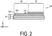
- FIG. 2 is a cross-sectional view illustrating an example of a to-be-coated object that was coated.
- the to-be-coated object 30 illustrated in FIG. 2 includes a base member 31, a primer layer 32, and a first coating layer 33.
- the base member 31 is, for example, a steel plate processed into a predetermined shape, and is subjected to an electrodeposition process as necessary to impart rust resistance thereto.
- the primer layer 32 is provided for imparting weather resistance, color development, and peeling resistance, for example.
- the first coating layer 33 is, for example, a base layer that has smoothness and weather resistance and imparts a desired coating color.
- a surface of the first coating layer 33 serves as a to-be-coated surface 30a to be coated by the coating device 1 according to the embodiment.
- a second coating layer 34 is located on the first coating layer 33 serving as the to-be-coated surface 30a.
- the second coating layer 34 is located so as to cover a portion of the first coating layer 33 with a coating material having a coating color different from that of the first coating layer 33.
- the to-be-coated object 30 becomes a coated body 38 that is coated in a so-called two tone color in which a region 36 where the second coating layer 34 is located and a region 35 where the first coating layer 33 is exposed without the second coating layer 34 being located are aligned with an end portion 37 of the second coating layer 34 as a boundary.
- the coating device 1 has been described such that the second coating layer 34 is located on the to-be-coated surface 30a on the first coating layer 33, but the present invention is not limited thereto, and the coating device 1 may be applied, for example, when the first coating layer 33 is located on a coated surface 32a on the primer layer 32.
- the coated body 38 is not limited to the example illustrated in FIG. 2 .
- a coating layer (not illustrated) may be located on the surfaces of the regions 35 and 36.
- the second coating layer 34 need not be included, and only the first coating layer 33 may be included, and the second coating layer 34 may be located on the entire surface of the first coating layer 33.
- the to-be-coated object 30 or the coated body 38 may further include one or a plurality of layers (not illustrated).
- FIG. 3 is a view illustrating an example of a head included in a coating device according to a first embodiment.
- FIG. 3 corresponds to a plan view of the head 10 and the to-be-coated object 30 facing the nozzle surface 12 (see FIG. 1 ) of the head 10 as viewed from a Z-axis positive direction side.
- the to-be-coated object 30 has a planar shape along an XY plane, such as a roof of a vehicle body, for example.
- the coating device 1 according to each embodiment has a common configuration, except for the movement of the head 10.
- other configurations such as the robot 20 and the control device 40, except for the head 10, are omitted from the drawings.
- the head 10 moves in an X-axis positive direction serving as a first direction in a state of facing the to-be-coated object 30.
- the head 10 may achieve a surface area coating speed of, for example, 1 m 2 /min or more and 5 m 2 /min or less.
- the head 10 may move in the X-axis direction at a predetermined speed of, for example, 1.67 ⁇ 10 2 mm/s or more and 41.67 ⁇ 10 2 mm/s or less.
- the coating device 1 may use two or more heads 10.
- the resolution of the head 10 can be, for example, 150 dots per inch (dpi) or more. More preferably, the resolution of the head 10 is 300 dpi or more. When the resolution of the head 10 is 150 dpi or more, the leveling property is improved and the quality of the coating film is improved. Note that the resolution of the head 10 need not necessarily be 150 dpi or more.
- the head 10 vibrates in a Y-axis direction serving as a second direction along the XY plane in parallel with the movement in the X-axis positive direction. As a result, the head 10 moves such that a locus 15 of a center 13 in plan view draws a sinusoidal waveform.
- the coating device 1 By the head 10 moving in the first direction while vibrating in the second direction in this way, even in a case where a gap between the discharge drops increases due to, for example, clogging of a portion of the discharge holes 11 (see FIG. 1 ), the discharge drops discharged from the discharge holes 11 located near the clogged discharge holes 11 can fill the gap.
- the coating quality can be improved.
- a spatial displacement d1 in the Y-axis direction due to the vibration of the head 10 can be 2 mm or less, for example, 0.07 mm or more and 2 mm or less. Accordingly, the gap between the discharge drops is easily filled.
- a vibration period T1 of the head 10 can be 2 mm or less, for example, 0.07 mm or more and 2 mm or less. By defining the vibration period T1 in this manner, the gap between the discharge drops is easily filled.
- a lower limit of the spatial displacement d1 of the head 10 may be set based on an interval of the discharge holes 11 (see FIG. 1 ) arranged in the second direction intersecting the movement direction of the head 10. This point will be described with reference to FIG. 4 .
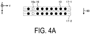
- FIGS. 4A to 4C are enlarged views comparing arrays of discharge drops discharged onto the to-be-coated object.
- each head 10 is illustrated as a head 10 including only one column (also referred to as a "row") of discharge holes 11 aligned in the Y-axis direction intersecting a movement direction 60 of each head 10.
- each portion where the coating material is discharged from the discharge hole 11 is illustrated as a discharge portion 16 (one example of a discharge drop), and each portion where the discharge portion 16 is intended to be located, but the coating material is not discharged, is illustrated as a non-discharge portion 16a.
- the non-discharge portions 16a are continuous along the movement direction 60 of the head 10. As a result, the non-discharge portions 16a are easily visually recognized as a coating streak.
- the spatial displacement d1 of the head 10 is two times or more of the interval P1 between adjacent ones of the discharge portions 16 in the Y-axis direction, in other words, the interval between the discharge holes 11, even when the non-discharge portions 16a are located side by side in the Y-axis direction as illustrated, the non-discharge portions 16a are less likely to be visually recognized, and the coating quality is improved.
- the vibration of the head 10 in the present embodiment the case where the vibration is performed by the predetermined spatial displacement d1 in the second direction (Y-axis direction) serving as a direction orthogonal to the first direction (X-axis direction) is exemplified, but the present invention is not limited thereto.
- the head 10 may vibrate in a direction intersecting the first direction.
- the head 10 may vibrate in the second direction and alternately vibrate in the direction intersecting the first direction, or may vibrate in a random direction.
- the non-discharge portions 16a are less likely to be visually recognized, and the coating quality is improved.
- the head 10 may vibrate in the Z-axis direction. In this case, for example, the size of the discharge drop can be changed, and the coating quality is improved.
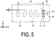
- FIG. 5 is a view illustrating an example of a head included in a coating device according to a second embodiment.
- the head 10 illustrated in FIG. 5 rotationally oscillates along the XY plane around an oscillation axis c1 along the Z-axis through the center 13, in parallel with the movement in the X-axis positive direction.
- the head 10 moving in the first direction while rotationally oscillating in this way, even in a case where the gap between the discharge drops increases due to, for example, the clogging of a portion of the discharge holes 11 (see FIG. 1 ), the discharge drops discharged from the discharge holes 11 located near the clogged discharge holes 11 can fill the gap.
- a spatial displacement d2 in the Y-axis direction due to the rotational oscillation of the head 10 can be 2 mm or less, for example, 0.07 mm or more and 2 mm or less. Accordingly, the gap between the discharge drops is easily filled.
- an oscillation angle ⁇ 1 can be set according to, for example, the array of the discharge holes 11 in the head 10 as illustrated in FIG. 6 .
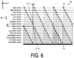
- FIG. 6 is a view illustrating an array of the discharge holes in the head included in the coating device according to the embodiment.
- the head 10 illustrated in FIG. 6 corresponds to a perspective of the array of the discharge holes 11 from the Z-axis positive direction side.
- the discharge holes 11 are aligned along the Y-axis direction, while the discharge holes 11 are located offset in the X-axis direction.
- the head 10 does not simultaneously discharge the coating material from all the discharge holes 11, but discharges the coating material for each "row" aligned in the Y-axis direction at a timing when the head 10 reaches a predetermined position while moving the head 10 in the movement direction 60.
- the discharge portions 16 can be located at an interval narrower than the interval between the discharge holes 11 aligned on the XY plane.
- the oscillation angle ⁇ 1 (see FIG. 5 ) can be set based on the combination in which the distance in the movement direction 60 is closest among the discharge holes 11 forming adjacent discharge drops.
- the oscillation angle ⁇ 1 (°) is defined so as to be Tan ⁇ 1 ⁇ y/x.
- the oscillation angle ⁇ 1 can be, for example, from 0.2° to 5°.
- an oscillation period T2 (see FIG. 5 ) of the head 10 can be 2 mm or less, for example, 0.07 mm or more and 2 mm or less. By defining the oscillation period T2 in this manner, the gap between the discharge drops is easily filled.
- the present invention is not limited thereto.
- the head 10 may include a plurality of different oscillation axes c1 and may rotationally oscillate randomly.
- the oscillation axis c1 may be located at a position offset from the center 13 along the X-axis. Further, the oscillation axis c1 may be located at a position offset in the X-axis direction from the center 13. This point will be described with reference to FIG. 7 .
- FIG. 7 is a view illustrating an example of a head included in a coating device according to a variation of a second embodiment.
- the head 10 illustrated in FIG. 7 rotationally oscillates around an oscillation axis c2 offset from the center 13 to the Y-axis negative direction side.
- a centrifugal force is applied to the coating material discharged from the head 10 in accordance with a distance from the oscillation axis c2.
- the discharge drops discharged from the discharge holes 11 located remote from the oscillation axis c2 may have a distorted shape.
- discharge drops having the desired shape are easily discharged.
- the head 10 is moved along the X-axis direction while being rotationally oscillated around the oscillation axis c2 near an end portion 37 with the region 35, a boundary of the regions 35 and 36 becomes sharp, and the appearance is improved.
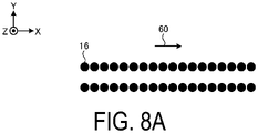
- FIGS. 8A to 8C are enlarged views comparing the arrays of discharge drops discharged onto the to-be-coated object.
- arrays of the coating drops discharged from two discharge holes 11 aligned in the Y-axis direction intersecting the movement direction 60 of the head 10 are illustrated as the discharge portions 16.
- FIG. 8A a case where the head 10 does not vibrate or rotationally oscillate is illustrated in FIG. 8A
- FIG. 8B a case where the head 10 vibrates
- FIG. 8C a case where the head 10 rotationally oscillates is illustrated in FIG. 8C .
- the intervals between adjacent ones of the discharge portions 16 are continuous so as to be along the movement direction 60 of the head 10, and the intervals are easily visually recognized as a coating streak.
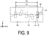
- FIG. 9 is a view illustrating an example of a head included in a coating device according to a third embodiment.
- the head 10 illustrated in FIG. 9 simultaneously performs the vibration described in the first embodiment and the rotational oscillation described in the second embodiment in parallel with the movement in the X-axis positive direction.
- the head 10 moving in the first direction while vibrating and rotationally oscillating in this manner, the discharge drops discharged from the discharge holes 11 located near the clogged discharge holes 11 can cover the gap, and the regularity of the discharge drops is degraded, and a coating streak is less likely to be visually recognized.
- the coating quality can be improved.
- the head 10 illustrated in FIG. 9 vibrates and rotationally oscillates so as to maximize an inclination with respect to the Y-axis direction, in other words the oscillation angle, when the amount of movement in the Y-axis direction is maximized, the clogging of the discharge holes 11 is easily covered, and the coating quality is improved.
- the vibration period T1 (see FIG. 3 ) and the oscillation period T2 (see FIG. 5 ) are the same, but the present invention is not limited thereto and may be different.
- the vibration period T1 serving as the period of vibration
- the oscillation period T2 serving as the period of the rotational oscillation different from each other in this manner, a coating streak is less likely to be visually recognized, and the coating quality is improved.
- the head 10 illustrated in FIG. 9 is illustrated as including an oscillation axis c3 overlapping with the center 13 of the head 10, but the present invention is not limited thereto.
- the oscillation axis c3 may be located at a position offset from the center 13 along the X-axis. Further, the oscillation axis c1 may be located at a position offset in the X-axis direction from the center 13.
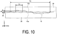
- FIG. 10 is a view illustrating an example of a head included in a coating device according to a fourth embodiment.
- the head 10 illustrated in FIG. 10 simultaneously performs vibrations having different periods in parallel with the movement in the X-axis positive direction. Note that in FIG. 10 , illustration of the head 10 is omitted.
- the locus 15 is a composite of a locus 15a of a first vibration having a spatial displacement d3 and a vibration period T3, and a locus 15b of a second vibration having a spatial displacement d4 and a vibration period T4.
- the head 10 moving in the first direction while simultaneously performing the vibrations having different periods in this manner, the discharge drops discharged from the discharge holes 11 located near the clogged discharge holes 11 can cover the gap, and a coating streak is less likely to be visually recognized.
- the coating quality can be improved.
- the spatial displacement d3 in the Y-axis direction due to the first vibration of the head 10 can be 2 mm or less, for example, 0.07 mm or more and 2 mm or less. Accordingly, the gap between the discharge drops is easily filled.
- the spatial displacement d4 in the Y-axis direction due to the second vibration of the head 10 can be 2 mm or less, for example, 0.07 mm or more and 2 mm or less. Accordingly, the gap between the discharge drops is easily filled.
- the spatial displacements d3 and d4 may be the same as or different from each other.
- the vibration period T3 due to the first vibration of the head 10 can be 2 mm or less, for example, 0.07 mm or more and 2 mm or less. By defining the vibration period T3 in this manner, the gap between the discharge drops is easily filled.
- the vibration period T4 due to the second vibration of the head 10 can be 100 mm or more, for example, 100 mm or more and 500 mm or less. By defining the vibration period T4 of the head 10 in this manner, the coating streak is less likely to be visually recognized.
- FIGS. 11 and 12 are views illustrating an example of a head included in a coating device according to a fifth embodiment.
- the center 13 of the head 10 moves along the X-axis direction serving as the first direction along the to-be-coated surface 30a of the to-be-coated object 30, and specifically along the locus 15 extending on the X-axis positive direction side.
- FIG. 11 corresponds to a plan view as the head 10 viewed from the Z-axis positive direction.
- FIG. 12 corresponds to front views of the head 10 at each position (positions 10-4 to 10-1) of the head 10 illustrated in FIG. 11 as respectively viewed from the X-axis positive direction in which the head 10 moves.
- the head 10 rotationally oscillates along a YZ plane around an oscillation axis c4 along the X-axis direction through the center 13, in parallel with the X-axis direction serving as the first direction.
- the head 10 rotationally oscillating around the oscillation axis along the first direction while moving in the first direction in this way, for example, the coating material in the nozzle is vibrated, making the coating material difficult to dry in the nozzle.
- a vibration period T5 of the head 10 can be 2 mm or less, for example, 0.07 mm or more and 2 mm or less. By defining the vibration period T5 in this manner, the gap between the discharge drops is easily filled.
- an oscillation angle ⁇ 2 can be set according to, for example, the array of the discharge holes 11 (see FIG. 1 ) in the head 10.
- the oscillation angle ⁇ 2 (°) of the head 10 can be defined, for example, such that ⁇ 2 > y/x.
- the oscillation angle ⁇ 2 can be, for example, from 0.2° to 5°.
- FIG. 13 is a view illustrating an example of a head included in a coating device according to a sixth embodiment.
- the head 10 according to the present embodiment differs from the head 10 included in the coating device 1 according to the fifth embodiment in that the head 10 vibrates in the Z-axis direction serving as a third direction such that an interval between the nozzle surface 12 and the to-be-coated surface 30a of the to-be-coated object 30 changes instead of rotational oscillation around the oscillation axis c4.
- FIG. 14 is a view illustrating an example of a coating material remaining in an interior channel of the head.
- a nozzle 8 located inside the head 10 supplies a coating material 18 to the discharge hole 11 located on the nozzle surface 12.
- a liquid surface 19 of the coating material 18 also moves in the Z-axis direction.
- the coating material 18 in the nozzle 8 is vibrated, making the coating material 18 difficult to dry in the nozzle 8. As a result, clogging of the discharge hole 11 can be reduced.
- the vibration period of the head 10 can be 2 mm or less, for example, 0.07 mm or more and 2 mm or less. By defining the vibration period in this manner, the gap between the discharge drops is easily filled.
- each of a spatial displacements d5 and d6 in the Z-axis direction due to the vibration of the head 10 can be 1 mm or less, for example, 0.07 mm or more and 1 mm or less. As a result, the coating unevenness can be reduced. Note that the spatial displacements d5 and d6 may be the same as or different from each other.
- the vibration of the head 10 in the Z-axis direction according to the present embodiment can be performed in combination with the vibration and oscillation of the head 10 according to another embodiment within a range in which no contradiction occurs in the processing content.
- the coating device 1 including the head 10 configured to discharge a single color coating material was described.
- robots 20 respectively holding heads 10 for discharging basic coating materials such as magenta (M), yellow (Y), cyan (C), and black (K) may be included.
- the coating device includes the head, the arm, and the controller.
- the head includes the nozzle surface.
- the arm holds the head.
- the controller controls movement of the head via the arm.
- the controller vibrates the head in the second direction intersecting with the first direction, and/or rotationally oscillates along the nozzle surface while moving the head in the first direction along the nozzle surface in a state where the nozzle surface and the to-be-coated object face each other.
- the nozzle surface includes the plurality of discharge holes configured to discharge the coating material, and the head vibrates and/or rotationally oscillates with a width equal to or more than the interval between adjacent ones of the discharge holes in the second direction intersecting the first direction.
- the nozzle surface includes the plurality of discharge holes for discharging the coating material, and the head vibrates and/or rotationally oscillates with a width equal to or more than two times of the interval between adjacent ones of the discharge holes in the second direction intersecting the first direction.
- the head rotationally oscillates along the nozzle surface while vibrating in the second direction intersecting the first direction.
- the regularity of the discharge drops is degraded, a coating streak is less likely to be visually recognized, and the coating quality is improved.
- the head rotationally oscillates such that the inclination with respect to the second direction is maximum when the spatial displacement in the second direction is maximum. As a result, the clogging of the discharge holes 11 is easily covered and the coating quality is improved.
- the period of vibration and the period of rotational oscillation are different from each other. As a result, a coating streak is less likely to be visually recognized, and the coating quality is improved.
- the head rotationally oscillates around the axis closer to an end portion of the coating region than a center in a plan view. As a result, the appearance of the end portion of the coating region is improved, and the coating quality is improved.
- the head moves in the second direction at a period different from a period of vibration while vibrating in the second direction intersecting the first direction.
- the coating device includes the head, the arm, and the controller.
- the head includes the nozzle surface.
- the arm holds the head.
- the controller controls movement of the head via the arm.
- the controller rotationally oscillates the head around the oscillation axis along the first direction while moving the head in the first direction along the to-be-coated surface of the to-be-coated object in a state where the nozzle surface and the to-be-coated object face each other.
- the head vibrates in the third direction intersecting the first direction so as to change the interval between the nozzle surface and the to-be-coated object.
Landscapes
- Engineering & Computer Science (AREA)
- Robotics (AREA)
- Coating Apparatus (AREA)
- Mechanical Engineering (AREA)
- Application Of Or Painting With Fluid Materials (AREA)
- Manipulator (AREA)
- Spray Control Apparatus (AREA)
Abstract
Description
- Disclosed embodiments relate to a coating device and a coating method.
- A coating device using an inkjet method is known. A head for discharging a coating material is mounted on such a coating device of an inkjet method.
-
- Patent Document 1:
JP 2013-202781 A - Patent Document 2:
JP 2012-506305 T - A coating device according to one aspect of an embodiment includes a head, an arm, and a controller. The head includes a nozzle surface. The arm holds the head. The controller controls movement of the head via the arm. The controller vibrates the head in a second direction intersecting a first direction, and/or rotationally oscillates the head along the nozzle surface while moving the head in the first direction along the nozzle surface in a state where the nozzle surface and a to-be-coated object face each other.
-
-
FIG. 1 is an explanatory view of a coating device according to an embodiment. -
FIG. 2 is a cross-sectional view illustrating an example of a to-be-coated object that was coated. -
FIG. 3 is a view illustrating an example of a head included in a coating device according to a first embodiment. -
FIG. 4A is an enlarged view comparing an array of discharge drops discharged onto a to-be-coated object. -
FIG. 4B is an enlarged view comparing an array of discharge drops discharged onto a to-be-coated object. -
FIG. 4C is an enlarged view comparing an array of discharge drops discharged onto a to-be-coated object. -
FIG. 5 is a view illustrating an example of a head included in a coating device according to a second embodiment. -
FIG. 6 is a view illustrating an array of discharge holes in a head included in a coating device according to an embodiment. -
FIG. 7 is a view illustrating an example of a head included in a coating device according to a variation of the second embodiment. -
FIG. 8A is an enlarged view comparing discharge drops discharged onto a to-be-coated object. -
FIG. 8B is an enlarged view comparing discharge drops discharged onto a to-be-coated object. -
FIG. 8C is an enlarged view comparing discharge drops discharged onto a to-be-coated object. -
FIG. 9 is a view illustrating an example of a head included in a coating device according to a third embodiment. -
FIG. 10 is a view illustrating an example of a head included in a coating device according to a fourth embodiment. -
FIG. 11 is a view illustrating an example of a head included in a coating device according to a fifth embodiment. -
FIG. 12 is a view illustrating an example of a head included in a coating device according to the fifth embodiment. -
FIG. 13 is a view illustrating an example of a head included in a coating device according to a six embodiment. -
FIG. 14 is a view illustrating an example of a coating material remaining in an interior channel of a head. - Embodiments of a coating device and a coating method disclosed in the present application will be described in detail below with reference to the accompanying drawings. Note that the present invention is not limited to the embodiments that will be described below.
- First, with reference to
FIG. 1 , a description will be given of an overview of a coating device according to an embodiment.FIG. 1 is an explanatory view of the coating device according to the embodiment. - As illustrated in
FIG. 1 , acoating device 1 includes ahead 10, arobot 20, and acontrol device 40. - The
head 10 is fixed to therobot 20. Thehead 10 moves in response to movement of therobot 20 controlled by thecontrol device 40. Thehead 10 can use, for example, an inkjet head of a valve type, a piezo type, or a thermal type. When a piezo type or thermal type inkjet head is used as thehead 10, high resolution is easily realized. - The
head 10 coats a to-be-coatedobject 30 by depositing a coating material discharged from a plurality ofdischarge holes 11 located on anozzle surface 12 onto a surface of the to-be-coatedobject 30 facing thenozzle surface 12. - The coating material is supplied to the
head 10 from a tank (not illustrated). Thehead 10 discharges the coating material supplied from the tank. The coating material is a mixture containing a volatile component and a nonvolatile component, and has fluidity. Note that the tank may be a reservoir (not illustrated) housed in thehead 10. - The volatile component is, for example, water, organic solvent, or alcohol, and adjusts the physical properties such as viscosity and surface tension of the coating material. The nonvolatile component contains, for example, a pigment, a resin material, and an additive. The pigment includes one or more colored pigments used depending on a desired coating color. The resin material is deposited on the to-
be-coated object 30 and forms a film. The additive is a functional material that is added, for example for purposes of weather resistance and the like. - Note that the coating material supplied to the
discharge holes 11 is prepared such that a desired coating color is expressed by mixing a plurality of colored pigments or coating materials at predetermined proportions. - The
robot 20 holds thehead 10. Therobot 20 is, for example, a six-axis articulated robot. Therobot 20 may be, for example, a vertical articulated robot or a horizontal articulated robot. Therobot 20 includes a plurality ofarms 21 with thehead 10 fixed to a tip of the plurality ofarms 21. Therobot 20 is fixed to a floor, a wall, a ceiling, or the like. Note that as long as the heldhead 10 can be moved properly, there is no limit to the degree of freedom of thearms 21 included in therobot 20. - The
control device 40 controls thecoating device 1. Thecontrol device 40 includes a controller 41 configured to control thecoating device 1, and a storage unit 45. The controller 41 includes adischarge controller 42 and anoperation controller 43. - The controller 41 includes a computer or various circuits including, for example, a central processing unit (CPU), a read only memory (ROM), a random access memory (RAM), a hard desk drive (HDD), and an input/output port. The CPU of such a computer functions as the controller 41 by, for example, reading and executing the program stored in the ROM. The controller 41 may also be configured by hardware such as an application specific integrated circuit (ASIC) or a field programmable gate array (FPGA). The
discharge controller 42 controls thehead 10 based on configuration information stored in the storage unit 45, and discharges the coating material from the plurality of discharge holes 11 toward the to-be-coated object 30. Theoperation controller 43 controls operations of the plurality ofarms 21 based on the configuration information stored in the storage unit 45, and controls movement of thehead 10 via thearms 21. The distance between thehead 10 and the to-be-coated object 30 is maintained at, for example, approximately from 0.5 to 14 mm. The detailed movement of thehead 10 will be described later. - The storage unit 45 corresponds to, for example, the ROM and the HDD. The ROM and the HDD can store configuration information for various controls in the
control device 40. The storage unit 45 stores information related to discharge control of the coating material by thehead 10. Further, the storage unit 45 stores information related to the operation control of the plurality ofarms 21. Note that the storage unit 45 may store data input by the user's instruction operation using a terminal apparatus (not illustrated) as instruction data for operating therobot 20. Further, the controller 41 may also acquire the configuration information via another computer or portable storage medium connected by a wired or wireless network. - The to-
be-coated object 30 is, for example, a vehicle body. The to-be-coated object 30 is placed on a conveying device (not illustrated), and is carried in and out. Thecoating device 1 according to an embodiment coats the to-be-coated object 30 in a state where the conveying device is stopped. Note that thecoating device 1 may coat the to-be-coated object 30 while the to-be-coated object 30 is being repeatedly conveyed and stopped, or may coat the to-be-coated object 30 while the to-be-coated object 30 is being conveyed. -
FIG. 2 is a cross-sectional view illustrating an example of a to-be-coated object that was coated. The to-be-coated object 30 illustrated inFIG. 2 includes abase member 31, aprimer layer 32, and afirst coating layer 33. Thebase member 31 is, for example, a steel plate processed into a predetermined shape, and is subjected to an electrodeposition process as necessary to impart rust resistance thereto. Theprimer layer 32 is provided for imparting weather resistance, color development, and peeling resistance, for example. Thefirst coating layer 33 is, for example, a base layer that has smoothness and weather resistance and imparts a desired coating color. A surface of thefirst coating layer 33 serves as a to-be-coated surface 30a to be coated by thecoating device 1 according to the embodiment. - A
second coating layer 34 is located on thefirst coating layer 33 serving as the to-be-coated surface 30a. Thesecond coating layer 34 is located so as to cover a portion of thefirst coating layer 33 with a coating material having a coating color different from that of thefirst coating layer 33. As a result, the to-be-coated object 30 becomes acoated body 38 that is coated in a so-called two tone color in which aregion 36 where thesecond coating layer 34 is located and aregion 35 where thefirst coating layer 33 is exposed without thesecond coating layer 34 being located are aligned with anend portion 37 of thesecond coating layer 34 as a boundary. - In the example illustrated in
FIG. 2 , thecoating device 1 has been described such that thesecond coating layer 34 is located on the to-be-coated surface 30a on thefirst coating layer 33, but the present invention is not limited thereto, and thecoating device 1 may be applied, for example, when thefirst coating layer 33 is located on acoated surface 32a on theprimer layer 32. - Note that the
coated body 38 is not limited to the example illustrated inFIG. 2 . For example, a coating layer (not illustrated) may be located on the surfaces of theregions second coating layer 34 need not be included, and only thefirst coating layer 33 may be included, and thesecond coating layer 34 may be located on the entire surface of thefirst coating layer 33. Further, the to-be-coated object 30 or thecoated body 38 may further include one or a plurality of layers (not illustrated). -
FIG. 3 is a view illustrating an example of a head included in a coating device according to a first embodiment.FIG. 3 corresponds to a plan view of thehead 10 and the to-be-coated object 30 facing the nozzle surface 12 (seeFIG. 1 ) of thehead 10 as viewed from a Z-axis positive direction side. Note that, for ease of explanation, the to-be-coated object 30 has a planar shape along an XY plane, such as a roof of a vehicle body, for example. - Further, in each of the embodiments described below, an example will be given of a case in which the
head 10 discharges a coating material that positions thesecond coating layer 34 in theregion 36. Further, thecoating device 1 according to each embodiment has a common configuration, except for the movement of thehead 10. As a result, other configurations, such as therobot 20 and thecontrol device 40, except for thehead 10, are omitted from the drawings. - As illustrated in
FIG. 3 , thehead 10 moves in an X-axis positive direction serving as a first direction in a state of facing the to-be-coated object 30. Thehead 10 may achieve a surface area coating speed of, for example, 1 m2/min or more and 5 m2/min or less. In order to achieve such a surface area coating speed, assuming the length of the print region of thehead 10 is 100 mm, thehead 10 may move in the X-axis direction at a predetermined speed of, for example, 1.67 × 102 mm/s or more and 41.67 × 102 mm/s or less. Note that, in this example, onehead 10 is used; however, thecoating device 1 may use two or more heads 10. - The resolution of the
head 10 can be, for example, 150 dots per inch (dpi) or more. More preferably, the resolution of thehead 10 is 300 dpi or more. When the resolution of thehead 10 is 150 dpi or more, the leveling property is improved and the quality of the coating film is improved. Note that the resolution of thehead 10 need not necessarily be 150 dpi or more. - Further, the
head 10 vibrates in a Y-axis direction serving as a second direction along the XY plane in parallel with the movement in the X-axis positive direction. As a result, thehead 10 moves such that alocus 15 of acenter 13 in plan view draws a sinusoidal waveform. - By the
head 10 moving in the first direction while vibrating in the second direction in this way, even in a case where a gap between the discharge drops increases due to, for example, clogging of a portion of the discharge holes 11 (seeFIG. 1 ), the discharge drops discharged from the discharge holes 11 located near the clogged discharge holes 11 can fill the gap. Thus, with thecoating device 1 according to the present embodiment, the coating quality can be improved. - Here, a spatial displacement d1 in the Y-axis direction due to the vibration of the
head 10 can be 2 mm or less, for example, 0.07 mm or more and 2 mm or less. Accordingly, the gap between the discharge drops is easily filled. - Further, a vibration period T1 of the
head 10 can be 2 mm or less, for example, 0.07 mm or more and 2 mm or less. By defining the vibration period T1 in this manner, the gap between the discharge drops is easily filled. - Further, a lower limit of the spatial displacement d1 of the
head 10 may be set based on an interval of the discharge holes 11 (seeFIG. 1 ) arranged in the second direction intersecting the movement direction of thehead 10. This point will be described with reference toFIG. 4 . -
FIGS. 4A to 4C are enlarged views comparing arrays of discharge drops discharged onto the to-be-coated object. For ease of illustration, eachhead 10 is illustrated as ahead 10 including only one column (also referred to as a "row") of discharge holes 11 aligned in the Y-axis direction intersecting amovement direction 60 of eachhead 10. In thehead 10, at a point 17-1 and a point 17-2 adjacent to the point 17-1, each portion where the coating material is discharged from thedischarge hole 11 is illustrated as a discharge portion 16 (one example of a discharge drop), and each portion where thedischarge portion 16 is intended to be located, but the coating material is not discharged, is illustrated as anon-discharge portion 16a. - As illustrated in
FIG. 4A , in a case where thehead 10 does not vibrate in the Y-axis direction, thenon-discharge portions 16a are continuous along themovement direction 60 of thehead 10. As a result, thenon-discharge portions 16a are easily visually recognized as a coating streak. - On the other hand, as illustrated in
FIG. 4B , by making the spatial displacement d1 of thehead 10 equal to or more than an interval P1 between adjacent ones of thedischarge portions 16 in the Y-axis direction, in other words, an interval between the discharge holes 11, thenon-discharge portions 16a become discontinuous. As a result, thenon-discharge portions 16a are less likely to be visually recognized as a coating streak, and the coating quality is improved. In particular, as illustrated inFIG. 4C , in a case where the spatial displacement d1 of thehead 10 is two times or more of the interval P1 between adjacent ones of thedischarge portions 16 in the Y-axis direction, in other words, the interval between the discharge holes 11, even when thenon-discharge portions 16a are located side by side in the Y-axis direction as illustrated, thenon-discharge portions 16a are less likely to be visually recognized, and the coating quality is improved. - Note that as the vibration of the
head 10 in the present embodiment, the case where the vibration is performed by the predetermined spatial displacement d1 in the second direction (Y-axis direction) serving as a direction orthogonal to the first direction (X-axis direction) is exemplified, but the present invention is not limited thereto. For example, thehead 10 may vibrate in a direction intersecting the first direction. Furthermore, thehead 10 may vibrate in the second direction and alternately vibrate in the direction intersecting the first direction, or may vibrate in a random direction. In this case as well, thenon-discharge portions 16a are less likely to be visually recognized, and the coating quality is improved. Further, thehead 10 may vibrate in the Z-axis direction. In this case, for example, the size of the discharge drop can be changed, and the coating quality is improved. -
FIG. 5 is a view illustrating an example of a head included in a coating device according to a second embodiment. Thehead 10 illustrated inFIG. 5 rotationally oscillates along the XY plane around an oscillation axis c1 along the Z-axis through thecenter 13, in parallel with the movement in the X-axis positive direction. - By the
head 10 moving in the first direction while rotationally oscillating in this way, even in a case where the gap between the discharge drops increases due to, for example, the clogging of a portion of the discharge holes 11 (seeFIG. 1 ), the discharge drops discharged from the discharge holes 11 located near the clogged discharge holes 11 can fill the gap. - Here, a spatial displacement d2 in the Y-axis direction due to the rotational oscillation of the
head 10 can be 2 mm or less, for example, 0.07 mm or more and 2 mm or less. Accordingly, the gap between the discharge drops is easily filled. Note that an oscillation angle θ1 can be set according to, for example, the array of the discharge holes 11 in thehead 10 as illustrated inFIG. 6 . -
FIG. 6 is a view illustrating an array of the discharge holes in the head included in the coating device according to the embodiment. Thehead 10 illustrated inFIG. 6 corresponds to a perspective of the array of the discharge holes 11 from the Z-axis positive direction side. - In the
head 10 illustrated inFIG. 6 , the discharge holes 11 are aligned along the Y-axis direction, while the discharge holes 11 are located offset in the X-axis direction. Thehead 10 does not simultaneously discharge the coating material from all the discharge holes 11, but discharges the coating material for each "row" aligned in the Y-axis direction at a timing when thehead 10 reaches a predetermined position while moving thehead 10 in themovement direction 60. As a result, thedischarge portions 16 can be located at an interval narrower than the interval between the discharge holes 11 aligned on the XY plane. - Here, the oscillation angle θ1 (see
FIG. 5 ) can be set based on the combination in which the distance in themovement direction 60 is closest among the discharge holes 11 forming adjacent discharge drops. In thehead 10 illustrated inFIG. 6 , assuming distances in the X-axis direction and the Y-axis direction are x and y, respectively, in the discharge holes 11-1 and 11-2, the oscillation angle θ1 (°) is defined so as to be Tan θ1 ≥ y/x. As a result, even when a portion of the discharge holes 11 is clogged, the discharge drops discharged from the discharge holes 11 located near the clogged discharge holes 11 can cover the gap. The oscillation angle θ1 can be, for example, from 0.2° to 5°. - Further, an oscillation period T2 (see
FIG. 5 ) of thehead 10 can be 2 mm or less, for example, 0.07 mm or more and 2 mm or less. By defining the oscillation period T2 in this manner, the gap between the discharge drops is easily filled. - Note that as the rotational oscillation in the present embodiment, the case where the
head 10 performs the rotational oscillation on the XY plane at the oscillation angle θ1 around the oscillation axis c1 is exemplified, but the present invention is not limited thereto. Thehead 10 may include a plurality of different oscillation axes c1 and may rotationally oscillate randomly. - Note that the oscillation axis c1 may be located at a position offset from the
center 13 along the X-axis. Further, the oscillation axis c1 may be located at a position offset in the X-axis direction from thecenter 13. This point will be described with reference toFIG. 7 . -
FIG. 7 is a view illustrating an example of a head included in a coating device according to a variation of a second embodiment. Thehead 10 illustrated inFIG. 7 rotationally oscillates around an oscillation axis c2 offset from thecenter 13 to the Y-axis negative direction side. In the rotationally oscillatinghead 10, a centrifugal force is applied to the coating material discharged from thehead 10 in accordance with a distance from the oscillation axis c2. Thus, the discharge drops discharged from the discharge holes 11 (seeFIG. 1 ) located remote from the oscillation axis c2 may have a distorted shape. In contrast, from the discharge holes 11 located at a location close to the oscillation axis c2, discharge drops having the desired shape are easily discharged. Thus, when thehead 10 is moved along the X-axis direction while being rotationally oscillated around the oscillation axis c2 near anend portion 37 with theregion 35, a boundary of theregions - As described above, by moving the
head 10 in the first direction along thenozzle surface 12 while vibrating or rotationally oscillating thehead 10 along thenozzle surface 12, in a state in which thenozzle surface 12 and the to-be-coated object 30 face each other, the clogging of the discharge holes 11 is covered and the coating quality is improved. However, sufficient coating quality may not necessarily be obtained only by vibrating or rotationally oscillating thehead 10. This point will be described with reference toFIGS. 8A to 8C . -
FIGS. 8A to 8C are enlarged views comparing the arrays of discharge drops discharged onto the to-be-coated object. For ease of illustration, arrays of the coating drops discharged from twodischarge holes 11 aligned in the Y-axis direction intersecting themovement direction 60 of thehead 10 are illustrated as thedischarge portions 16. Further, a case where thehead 10 does not vibrate or rotationally oscillate is illustrated inFIG. 8A , a case where thehead 10 vibrates is illustrated inFIG. 8B , and a case where thehead 10 rotationally oscillates is illustrated inFIG. 8C . - As illustrated in
FIG. 8A , in the case where thehead 10 does not vibrate or rotationally oscillate in the Y-axis direction, the intervals between adjacent ones of thedischarge portions 16 are continuous so as to be along themovement direction 60 of thehead 10, and the intervals are easily visually recognized as a coating streak. - On the other hand, as illustrated in
FIGS. 8B and8C , in the case where thehead 10 vibrates or rotationally oscillates in the Y-axis direction, the intervals between thedischarge portions 16 along themovement direction 60 become irregular. as a result, the intervals are less likely to be visually recognized as a coating streak. On the other hand, when the intervals between thedischarge portions 16 located at an angle with respect to themovement direction 60 are regular due to the vibration of thehead 10, the intervals may be visually recognized as a coating streak. In such a case, as will be described below, a countermeasure can be taken by making the vibration or the rotational oscillation of thehead 10 into a complex motion. -
FIG. 9 is a view illustrating an example of a head included in a coating device according to a third embodiment. Thehead 10 illustrated inFIG. 9 simultaneously performs the vibration described in the first embodiment and the rotational oscillation described in the second embodiment in parallel with the movement in the X-axis positive direction. - By the
head 10 moving in the first direction while vibrating and rotationally oscillating in this manner, the discharge drops discharged from the discharge holes 11 located near the clogged discharge holes 11 can cover the gap, and the regularity of the discharge drops is degraded, and a coating streak is less likely to be visually recognized. Thus, with thehead 10 included in thecoating device 1 according to the third embodiment, the coating quality can be improved. - Further, when the
head 10 illustrated inFIG. 9 vibrates and rotationally oscillates so as to maximize an inclination with respect to the Y-axis direction, in other words the oscillation angle, when the amount of movement in the Y-axis direction is maximized, the clogging of the discharge holes 11 is easily covered, and the coating quality is improved. - Note that in
FIG. 9 , the vibration period T1 (seeFIG. 3 ) and the oscillation period T2 (seeFIG. 5 ) are the same, but the present invention is not limited thereto and may be different. By making the vibration period T1 serving as the period of vibration and the oscillation period T2 serving as the period of the rotational oscillation different from each other in this manner, a coating streak is less likely to be visually recognized, and the coating quality is improved. - The
head 10 illustrated inFIG. 9 is illustrated as including an oscillation axis c3 overlapping with thecenter 13 of thehead 10, but the present invention is not limited thereto. The oscillation axis c3 may be located at a position offset from thecenter 13 along the X-axis. Further, the oscillation axis c1 may be located at a position offset in the X-axis direction from thecenter 13. -
FIG. 10 is a view illustrating an example of a head included in a coating device according to a fourth embodiment. Thehead 10 illustrated inFIG. 10 simultaneously performs vibrations having different periods in parallel with the movement in the X-axis positive direction. Note that inFIG. 10 , illustration of thehead 10 is omitted. - As illustrated in
FIG. 10 , thecenter 13 of thehead 10 moves along thelocus 15. Thelocus 15 is a composite of alocus 15a of a first vibration having a spatial displacement d3 and a vibration period T3, and alocus 15b of a second vibration having a spatial displacement d4 and a vibration period T4. - By the
head 10 moving in the first direction while simultaneously performing the vibrations having different periods in this manner, the discharge drops discharged from the discharge holes 11 located near the clogged discharge holes 11 can cover the gap, and a coating streak is less likely to be visually recognized. Thus, with thehead 10 included in thecoating device 1 according to the fourth embodiment, the coating quality can be improved. - Here, the spatial displacement d3 in the Y-axis direction due to the first vibration of the
head 10 can be 2 mm or less, for example, 0.07 mm or more and 2 mm or less. Accordingly, the gap between the discharge drops is easily filled. Further, the spatial displacement d4 in the Y-axis direction due to the second vibration of thehead 10 can be 2 mm or less, for example, 0.07 mm or more and 2 mm or less. Accordingly, the gap between the discharge drops is easily filled. Note that the spatial displacements d3 and d4 may be the same as or different from each other. - Further, the vibration period T3 due to the first vibration of the
head 10 can be 2 mm or less, for example, 0.07 mm or more and 2 mm or less. By defining the vibration period T3 in this manner, the gap between the discharge drops is easily filled. Further, the vibration period T4 due to the second vibration of thehead 10 can be 100 mm or more, for example, 100 mm or more and 500 mm or less. By defining the vibration period T4 of thehead 10 in this manner, the coating streak is less likely to be visually recognized. -
FIGS. 11 and12 are views illustrating an example of a head included in a coating device according to a fifth embodiment. In thehead 10 according to the present embodiment, thecenter 13 of thehead 10 moves along the X-axis direction serving as the first direction along the to-be-coated surface 30a of the to-be-coated object 30, and specifically along thelocus 15 extending on the X-axis positive direction side. -
FIG. 11 corresponds to a plan view as thehead 10 viewed from the Z-axis positive direction.FIG. 12 corresponds to front views of thehead 10 at each position (positions 10-4 to 10-1) of thehead 10 illustrated inFIG. 11 as respectively viewed from the X-axis positive direction in which thehead 10 moves. - As illustrated in
FIG. 12 , thehead 10 rotationally oscillates along a YZ plane around an oscillation axis c4 along the X-axis direction through thecenter 13, in parallel with the X-axis direction serving as the first direction. - By the
head 10 rotationally oscillating around the oscillation axis along the first direction while moving in the first direction in this way, for example, the coating material in the nozzle is vibrated, making the coating material difficult to dry in the nozzle. - Here, a vibration period T5 of the
head 10 can be 2 mm or less, for example, 0.07 mm or more and 2 mm or less. By defining the vibration period T5 in this manner, the gap between the discharge drops is easily filled. - Further, an oscillation angle θ2 can be set according to, for example, the array of the discharge holes 11 (see
FIG. 1 ) in thehead 10. Specifically, in a case where the discharge holes 11 of thehead 10 are arranged as illustrated inFIG. 6 , the oscillation angle θ2 (°) of thehead 10 can be defined, for example, such that θ2 > y/x. As a result, even when a portion of the discharge holes 11 is clogged, the discharge drops discharged from the discharge holes 11 located near the clogged discharge holes 11 can cover the gap. The oscillation angle θ2 can be, for example, from 0.2° to 5°. -
FIG. 13 is a view illustrating an example of a head included in a coating device according to a sixth embodiment. Thehead 10 according to the present embodiment differs from thehead 10 included in thecoating device 1 according to the fifth embodiment in that thehead 10 vibrates in the Z-axis direction serving as a third direction such that an interval between thenozzle surface 12 and the to-be-coated surface 30a of the to-be-coated object 30 changes instead of rotational oscillation around the oscillation axis c4. -
FIG. 14 is a view illustrating an example of a coating material remaining in an interior channel of the head. As illustrated inFIG. 14 , anozzle 8 located inside thehead 10 supplies acoating material 18 to thedischarge hole 11 located on thenozzle surface 12. By thehead 10 vibrating in the Z-axis direction, aliquid surface 19 of thecoating material 18 also moves in the Z-axis direction. - By the
head 10 oscillating in the Z-axis direction serving as the third direction while moving in the X-axis direction serving as the first direction in this manner, for example, thecoating material 18 in thenozzle 8 is vibrated, making thecoating material 18 difficult to dry in thenozzle 8. As a result, clogging of thedischarge hole 11 can be reduced. - Hear, the vibration period of the
head 10 can be 2 mm or less, for example, 0.07 mm or more and 2 mm or less. By defining the vibration period in this manner, the gap between the discharge drops is easily filled. - Further, each of a spatial displacements d5 and d6 in the Z-axis direction due to the vibration of the
head 10 can be 1 mm or less, for example, 0.07 mm or more and 1 mm or less. As a result, the coating unevenness can be reduced. Note that the spatial displacements d5 and d6 may be the same as or different from each other. - Note that the vibration of the
head 10 in the Z-axis direction according to the present embodiment can be performed in combination with the vibration and oscillation of thehead 10 according to another embodiment within a range in which no contradiction occurs in the processing content. - Each embodiment according to the present invention was described above. However, the present invention is not limited to the embodiments described above, and various modifications can be made without departing from the essential spirit of the present invention. For example, in the embodiments described above, the
coating device 1 including thehead 10 configured to discharge a single color coating material was described. However, for example,robots 20 respectively holdingheads 10 for discharging basic coating materials such as magenta (M), yellow (Y), cyan (C), and black (K) may be included. - As described above, the coating device according to each of the embodiments includes the head, the arm, and the controller. The head includes the nozzle surface. The arm holds the head. The controller controls movement of the head via the arm. The controller vibrates the head in the second direction intersecting with the first direction, and/or rotationally oscillates along the nozzle surface while moving the head in the first direction along the nozzle surface in a state where the nozzle surface and the to-be-coated object face each other. As a result, the clogging of the discharge holes 11 can be covered and the coating quality is improved.
- Further, in the coating device according to the embodiments, the nozzle surface includes the plurality of discharge holes configured to discharge the coating material, and the head vibrates and/or rotationally oscillates with a width equal to or more than the interval between adjacent ones of the discharge holes in the second direction intersecting the first direction. As a result, the clogging of the discharge holes 11 is easily covered and the coating quality is improved.
- Further, in the coating device according to the embodiments, the nozzle surface includes the plurality of discharge holes for discharging the coating material, and the head vibrates and/or rotationally oscillates with a width equal to or more than two times of the interval between adjacent ones of the discharge holes in the second direction intersecting the first direction. As a result, the clogging of the discharge holes 11 is easily covered and the coating quality is improved.
- Further, in the coating device according to an embodiment, the head rotationally oscillates along the nozzle surface while vibrating in the second direction intersecting the first direction. As a result, the regularity of the discharge drops is degraded, a coating streak is less likely to be visually recognized, and the coating quality is improved.
- Further, in the coating device according to the embodiments, the head rotationally oscillates such that the inclination with respect to the second direction is maximum when the spatial displacement in the second direction is maximum. As a result, the clogging of the discharge holes 11 is easily covered and the coating quality is improved.
- Further, in the coating device according to the embodiments, in the head, the period of vibration and the period of rotational oscillation are different from each other. As a result, a coating streak is less likely to be visually recognized, and the coating quality is improved.
- Further, in the coating device according to the embodiments, the head rotationally oscillates around the axis closer to an end portion of the coating region than a center in a plan view. As a result, the appearance of the end portion of the coating region is improved, and the coating quality is improved.
- Further, in the coating device according to the embodiments, the head moves in the second direction at a period different from a period of vibration while vibrating in the second direction intersecting the first direction. As a result, a coating streak is less likely to be visually recognized, and the coating quality is improved.
- Further, the coating device according to the embodiments includes the head, the arm, and the controller. The head includes the nozzle surface. The arm holds the head. The controller controls movement of the head via the arm. The controller rotationally oscillates the head around the oscillation axis along the first direction while moving the head in the first direction along the to-be-coated surface of the to-be-coated object in a state where the nozzle surface and the to-be-coated object face each other. As a result, the clogging of the discharge holes 11 can be reduced and the coating quality is improved.
- Further, in the coating device according to the embodiments, the head vibrates in the third direction intersecting the first direction so as to change the interval between the nozzle surface and the to-be-coated object. As a result, the clogging of the discharge holes 11 can be reduced and the coating quality is improved.
- Additional effects and variations can be easily derived by a person skilled in the art. Thus, a wide variety of aspects of the present invention are not limited to the specific details and representative embodiments represented and described above. Accordingly, various changes are possible without departing from the spirit or scope of the general inventive concepts defined by the appended claims and their equivalents.
-
- 1 Coating device
- 10 Head
- 11 Discharge hole
- 12 Nozzle surface
- 16 Discharge portion
- 16a Non-discharge portion
- 20 Robot
- 21 Arm
- 30 To-be-coated object
- 30a To-be-coated surface
- 40 Control device
- 41 Controller
- 42 Discharge controller
- 43 Operation controller
- 45 Storage unit
Claims (15)
- A coating device comprising:a head comprising a nozzle surface;an arm configured to hold the head; anda controller configured to control movement of the head via the arm,wherein the controller is configured to vibratethe head in a second direction intersecting a first direction, and/or rotationally oscillate the head along the nozzle surface while moving the head in the first direction along the nozzle surface when the nozzle surface faces a to-be-coated object.
- The coating device according to claim 1,wherein the nozzle surface comprises a plurality of discharge holes configured to discharge a coating material, andthe head vibrates and/or rotationally oscillates with a width equal to or more greater than an interval between adjacent discharge holes of the plurality of discharge holes in the second direction intersecting the first direction.
- The coating device according to claim 1,wherein the nozzle surface comprises a plurality of discharge holes configured to discharge a coating material, andthe head vibrates and/or rotationally oscillates with two times or more of an interval between adjacent discharge holes of the plurality of discharge holes in the second direction intersecting the first direction.
- The coating device according to any one of claims 1 to 3,
wherein the head vibrates and/or rotationally oscillates in the second direction intersecting the first direction with a width of 2 mm or less. - The coating device according to any one of claims 1 to 3,
wherein the head vibrates and/or rotationally oscillates with a period such that a spatial displacement in the first direction is 2 mm or less. - The coating device according to claim 1,
wherein the head rotationally oscillates along the nozzle surface while vibrating in the second direction intersecting the first direction. - The coating device according to claim 6,
wherein the head rotationally oscillates such that an inclination with respect to the second direction is maximum when a spatial displacement in the second direction is maximum. - The coating device according to claim 6 or 7,
wherein a period that the head vibrates is different than a period that the head rotationally oscillates. - The coating device according to claim 1,
wherein the head rotationally oscillates around an axis closer to an end portion of a coating region than a center axis of the coating region in a plan view. - The coating device according to claim 1,
wherein a period that the head moves in the second direction is different than a period that the head vibrates in the second direction intersecting the first direction. - The coating device according to claim 1,
wherein the arm vibrates the head in the second direction, and/or rotationally oscillates the head along the nozzle surface while moving the head in the first direction. - A coating device comprising:a head comprising a nozzle surface;an arm configured to hold the head; anda controller configured to control movement of the head via the arm,wherein the controller is configured to rotationally oscillate the head around an oscillation axis along a first direction while moving the head in the first direction along a to-be-coated surface of a to-be-coated object then the nozzle surface faces the to-be-coated object.
- The coating device according to any one of claims 1 to 12,
wherein the head vibrates in a third direction intersecting the first direction and changes an interval between the nozzle surface and the to-be-coated object. - The coating device according to any one of claims 1 to 13,
wherein a resolution of the head is 150 dpi or more. - A coating method comprising:positioning a nozzle surface of a head to face a to-be-coated object;oscillating the head in a second direction intersecting a first direction and/or rotationally oscillating the head along the nozzle surface while moving the head in the first direction along the nozzle surface; anddischarging a coating material from the nozzle surface while moving the head.
Applications Claiming Priority (2)
| Application Number | Priority Date | Filing Date | Title |
|---|---|---|---|
| JP2019141799 | 2019-07-31 | ||
| PCT/JP2020/029533 WO2021020577A1 (en) | 2019-07-31 | 2020-07-31 | Coating device and coating method |
Publications (3)
| Publication Number | Publication Date |
|---|---|
| EP4005687A1 true EP4005687A1 (en) | 2022-06-01 |
| EP4005687A4 EP4005687A4 (en) | 2023-08-16 |
| EP4005687B1 EP4005687B1 (en) | 2025-07-09 |
Family
ID=74228961
Family Applications (1)
| Application Number | Title | Priority Date | Filing Date |
|---|---|---|---|
| EP20847795.0A Active EP4005687B1 (en) | 2019-07-31 | 2020-07-31 | Coating device and coating method |
Country Status (5)
| Country | Link |
|---|---|
| US (1) | US20220274129A1 (en) |
| EP (1) | EP4005687B1 (en) |
| JP (2) | JP7204925B2 (en) |
| CN (1) | CN114173936A (en) |
| WO (1) | WO2021020577A1 (en) |
Cited By (1)
| Publication number | Priority date | Publication date | Assignee | Title |
|---|---|---|---|---|
| EP4659868A1 (en) * | 2024-06-06 | 2025-12-10 | Abb Schweiz Ag | Painting robot |
Families Citing this family (4)
| Publication number | Priority date | Publication date | Assignee | Title |
|---|---|---|---|---|
| EP4023344B1 (en) * | 2019-08-30 | 2025-11-12 | Kyocera Corporation | Painting device, painted film, and painting method |
| WO2023190533A1 (en) * | 2022-03-31 | 2023-10-05 | 京セラ株式会社 | Coating method and coating device |
| JP7628210B1 (en) * | 2024-05-30 | 2025-02-07 | アーベーベー・シュバイツ・アーゲー | Painting robot and painting method |
| DE102024128870A1 (en) * | 2024-10-07 | 2026-04-09 | HighLine Technology GmbH | Device and its use for coating a substrate over a large area |
Family Cites Families (26)
| Publication number | Priority date | Publication date | Assignee | Title |
|---|---|---|---|---|
| US4349828A (en) * | 1980-02-04 | 1982-09-14 | Xerox Corporation | Method and apparatus for oscillating an array of marking elements |
| US4894262A (en) * | 1988-10-24 | 1990-01-16 | Api, Inc. | Lumber end sealing machine |
| SE513145C2 (en) * | 1997-10-24 | 2000-07-17 | Abb Flexible Automation As | Device for pivoting a spray nozzle arranged on a robot arm |
| US6966950B2 (en) * | 1998-03-25 | 2005-11-22 | Winiewicz Anthony E | Method and apparatus for treating underground pipeline |
| JP2002099096A (en) * | 2000-09-25 | 2002-04-05 | Miki Kikaku:Kk | Flexo plate making method |
| JP4790107B2 (en) * | 2000-10-13 | 2011-10-12 | オリンパス株式会社 | Printer |
| JP3953776B2 (en) * | 2001-01-15 | 2007-08-08 | セイコーエプソン株式会社 | Material discharging apparatus and method, color filter manufacturing apparatus and manufacturing method, liquid crystal device manufacturing apparatus and manufacturing method, EL apparatus manufacturing apparatus and manufacturing method |
| JP2005305869A (en) * | 2004-04-22 | 2005-11-04 | Seiko Epson Corp | Droplet discharge device, head discharge performance maintaining device, head discharge performance maintaining method, electro-optical device manufacturing method, electro-optical device, and electronic apparatus |
| KR100677579B1 (en) * | 2005-04-26 | 2007-02-02 | 삼성전자주식회사 | Inkjet image forming apparatus |
| KR100750161B1 (en) * | 2006-02-02 | 2007-08-17 | 삼성전자주식회사 | Defective nozzle compensation method and apparatus for inkjet image forming apparatus |
| JP2008036947A (en) * | 2006-08-04 | 2008-02-21 | Ricoh Co Ltd | Liquid ejection device and liquid ejection method |
| JP4455578B2 (en) * | 2006-12-27 | 2010-04-21 | シャープ株式会社 | Droplet discharge drawing apparatus, droplet discharge drawing method, and droplet discharge drawing program |
| FI119922B (en) * | 2007-07-04 | 2009-05-15 | Theta Optics Ltd Oy | Method and apparatus for coating products |
| EP2229282A1 (en) * | 2007-12-31 | 2010-09-22 | Exatec, LLC. | Apparatus and method for printing three-dimensional articles |
| DE102008053178A1 (en) * | 2008-10-24 | 2010-05-12 | Dürr Systems GmbH | Coating device and associated coating method |
| JP5391763B2 (en) * | 2009-03-19 | 2014-01-15 | セイコーエプソン株式会社 | Fluid ejection device |
| GB0907362D0 (en) * | 2009-04-29 | 2009-06-10 | Ten Cate Itex B V | Print carriage |
| JP2011148228A (en) * | 2010-01-22 | 2011-08-04 | Mimaki Engineering Co Ltd | Inkjet recorder |
| US9493019B2 (en) * | 2011-06-10 | 2016-11-15 | Hewlett-Packard Development Company, L.P. | Printing system with oscillating pagewide printhead |
| DE102012006371A1 (en) * | 2012-03-29 | 2012-07-05 | Heidelberger Druckmaschinen Aktiengesellschaft | Method for printing image on body i.e. tank of e.g. passenger car, involves generating three or higher-dimension raster matrix data to control inkjet printhead, and printing image with inkjet printhead using raster data |
| DE102012006370A1 (en) * | 2012-03-29 | 2013-10-02 | Heidelberger Druckmaschinen Aktiengesellschaft | System for printing on an object |
| ITUB20159465A1 (en) * | 2015-12-16 | 2017-06-16 | Turbocoating S P A | METHOD OF DEPOSITION THERMAL SPRAY OF A COVER ON A SURFACE AND APPARATUS |
| US9844932B2 (en) * | 2016-01-28 | 2017-12-19 | Riso Kagaku Corporation | Inkjet printing machine |
| DE102016117211A1 (en) * | 2016-09-13 | 2018-03-15 | Schmid Rhyner Ag | Method and device for ink-jet application on flat substrates |
| DE102016014944A1 (en) * | 2016-12-14 | 2018-06-14 | Dürr Systems Ag | Coating method and corresponding coating device |
| JP6996965B2 (en) * | 2017-12-25 | 2022-01-17 | 東レエンジニアリング株式会社 | Coating device and coating method |
-
2020
- 2020-07-31 CN CN202080053994.7A patent/CN114173936A/en active Pending
- 2020-07-31 EP EP20847795.0A patent/EP4005687B1/en active Active
- 2020-07-31 WO PCT/JP2020/029533 patent/WO2021020577A1/en not_active Ceased
- 2020-07-31 JP JP2021535470A patent/JP7204925B2/en active Active
- 2020-07-31 US US17/631,419 patent/US20220274129A1/en active Pending
-
2022
- 2022-12-28 JP JP2022212225A patent/JP7617891B2/en active Active
Cited By (1)
| Publication number | Priority date | Publication date | Assignee | Title |
|---|---|---|---|---|
| EP4659868A1 (en) * | 2024-06-06 | 2025-12-10 | Abb Schweiz Ag | Painting robot |
Also Published As
| Publication number | Publication date |
|---|---|
| JP7204925B2 (en) | 2023-01-16 |
| JPWO2021020577A1 (en) | 2021-02-04 |
| JP2023052170A (en) | 2023-04-11 |
| EP4005687B1 (en) | 2025-07-09 |
| EP4005687A4 (en) | 2023-08-16 |
| CN114173936A (en) | 2022-03-11 |
| WO2021020577A1 (en) | 2021-02-04 |
| US20220274129A1 (en) | 2022-09-01 |
| JP7617891B2 (en) | 2025-01-20 |
Similar Documents
| Publication | Publication Date | Title |
|---|---|---|
| EP4005687B1 (en) | Coating device and coating method | |
| EP4023343B1 (en) | Coating device, coating film, and coating method | |
| EP3789123B1 (en) | Coating machine and coating method | |
| CN112912253B (en) | Drop-on-demand surface coating | |
| JP7231789B2 (en) | Coating robot and coating method using coating robot | |
| JP6948482B1 (en) | Painting robot system and painting method | |
| EP4201683A1 (en) | Liquid discharge apparatus, liquid discharge method, and carrier medium | |
| JP2016123942A (en) | Ink jet printing method and ink jet coater | |
| CN115052686B (en) | Coating equipment, coating methods and procedures | |
| JP6839227B2 (en) | Droplet attachment device | |
| EP4023344B1 (en) | Painting device, painted film, and painting method | |
| EP4501468A1 (en) | Coating method and coating device | |
| EP4234101B1 (en) | Liquid discharge apparatus, liquid discharge method, and carrier medium | |
| EP4417434A1 (en) | Three-dimensional object printing apparatus and printing method | |
| CN114641352B (en) | Coating film, motor vehicle and coating method | |
| US20220395859A1 (en) | Coating film, automobile, and coating method | |
| JP2024092140A (en) | Painting system and painting method | |
| CN104228339A (en) | Apparatus for printing on a curved surface of an object through an ink jet print head |
Legal Events
| Date | Code | Title | Description |
|---|---|---|---|
| STAA | Information on the status of an ep patent application or granted ep patent |
Free format text: STATUS: THE INTERNATIONAL PUBLICATION HAS BEEN MADE |
|
| PUAI | Public reference made under article 153(3) epc to a published international application that has entered the european phase |
Free format text: ORIGINAL CODE: 0009012 |
|
| STAA | Information on the status of an ep patent application or granted ep patent |
Free format text: STATUS: REQUEST FOR EXAMINATION WAS MADE |
|
| 17P | Request for examination filed |
Effective date: 20220128 |
|
| AK | Designated contracting states |
Kind code of ref document: A1 Designated state(s): AL AT BE BG CH CY CZ DE DK EE ES FI FR GB GR HR HU IE IS IT LI LT LU LV MC MK MT NL NO PL PT RO RS SE SI SK SM TR |
|
| DAV | Request for validation of the european patent (deleted) | ||
| DAX | Request for extension of the european patent (deleted) | ||
| P01 | Opt-out of the competence of the unified patent court (upc) registered |
Effective date: 20230505 |
|
| REG | Reference to a national code |
Ref country code: DE Ref legal event code: R079 Free format text: PREVIOUS MAIN CLASS: B05C0011100000 Ipc: B05B0013040000 Ref country code: DE Ref legal event code: R079 Ref document number: 602020054333 Country of ref document: DE Free format text: PREVIOUS MAIN CLASS: B05C0011100000 Ipc: B05B0013040000 |
|
| A4 | Supplementary search report drawn up and despatched |
Effective date: 20230713 |
|
| RIC1 | Information provided on ipc code assigned before grant |
Ipc: B05D 7/00 20060101ALN20230707BHEP Ipc: B05D 7/14 20060101ALN20230707BHEP Ipc: B25J 9/16 20060101ALI20230707BHEP Ipc: B41J 2/01 20060101ALI20230707BHEP Ipc: B05D 1/26 20060101ALI20230707BHEP Ipc: B05B 15/50 20180101ALI20230707BHEP Ipc: B05B 13/04 20060101AFI20230707BHEP |
|
| GRAP | Despatch of communication of intention to grant a patent |
Free format text: ORIGINAL CODE: EPIDOSNIGR1 |
|
| STAA | Information on the status of an ep patent application or granted ep patent |
Free format text: STATUS: GRANT OF PATENT IS INTENDED |
|
| RIC1 | Information provided on ipc code assigned before grant |
Ipc: B05D 7/00 20060101ALN20250108BHEP Ipc: B05D 7/14 20060101ALN20250108BHEP Ipc: B25J 9/16 20060101ALI20250108BHEP Ipc: B41J 2/01 20060101ALI20250108BHEP Ipc: B05D 1/26 20060101ALI20250108BHEP Ipc: B05B 15/50 20180101ALI20250108BHEP Ipc: B05B 13/04 20060101AFI20250108BHEP |
|
| INTG | Intention to grant announced |
Effective date: 20250130 |
|
| GRAS | Grant fee paid |
Free format text: ORIGINAL CODE: EPIDOSNIGR3 |
|
| GRAA | (expected) grant |
Free format text: ORIGINAL CODE: 0009210 |
|
| STAA | Information on the status of an ep patent application or granted ep patent |
Free format text: STATUS: THE PATENT HAS BEEN GRANTED |
|
| AK | Designated contracting states |
Kind code of ref document: B1 Designated state(s): AL AT BE BG CH CY CZ DE DK EE ES FI FR GB GR HR HU IE IS IT LI LT LU LV MC MK MT NL NO PL PT RO RS SE SI SK SM TR |
|
| REG | Reference to a national code |
Ref country code: GB Ref legal event code: FG4D |
|
| REG | Reference to a national code |
Ref country code: CH Ref legal event code: EP |
|
| REG | Reference to a national code |
Ref country code: IE Ref legal event code: FG4D |
|
| REG | Reference to a national code |
Ref country code: DE Ref legal event code: R096 Ref document number: 602020054333 Country of ref document: DE |
|
| PGFP | Annual fee paid to national office [announced via postgrant information from national office to epo] |
Ref country code: DE Payment date: 20250813 Year of fee payment: 6 |
|
| REG | Reference to a national code |
Ref country code: NL Ref legal event code: MP Effective date: 20250709 |
|
| PG25 | Lapsed in a contracting state [announced via postgrant information from national office to epo] |
Ref country code: PT Free format text: LAPSE BECAUSE OF FAILURE TO SUBMIT A TRANSLATION OF THE DESCRIPTION OR TO PAY THE FEE WITHIN THE PRESCRIBED TIME-LIMIT Effective date: 20251110 |
|
| PG25 | Lapsed in a contracting state [announced via postgrant information from national office to epo] |
Ref country code: NL Free format text: LAPSE BECAUSE OF FAILURE TO SUBMIT A TRANSLATION OF THE DESCRIPTION OR TO PAY THE FEE WITHIN THE PRESCRIBED TIME-LIMIT Effective date: 20250709 |
|
| REG | Reference to a national code |
Ref country code: AT Ref legal event code: MK05 Ref document number: 1811376 Country of ref document: AT Kind code of ref document: T Effective date: 20250709 |
|
| PG25 | Lapsed in a contracting state [announced via postgrant information from national office to epo] |
Ref country code: IS Free format text: LAPSE BECAUSE OF FAILURE TO SUBMIT A TRANSLATION OF THE DESCRIPTION OR TO PAY THE FEE WITHIN THE PRESCRIBED TIME-LIMIT Effective date: 20251109 |
|
| PG25 | Lapsed in a contracting state [announced via postgrant information from national office to epo] |
Ref country code: NO Free format text: LAPSE BECAUSE OF FAILURE TO SUBMIT A TRANSLATION OF THE DESCRIPTION OR TO PAY THE FEE WITHIN THE PRESCRIBED TIME-LIMIT Effective date: 20251009 |
|
| REG | Reference to a national code |
Ref country code: LT Ref legal event code: MG9D |
|
| PG25 | Lapsed in a contracting state [announced via postgrant information from national office to epo] |
Ref country code: AT Free format text: LAPSE BECAUSE OF FAILURE TO SUBMIT A TRANSLATION OF THE DESCRIPTION OR TO PAY THE FEE WITHIN THE PRESCRIBED TIME-LIMIT Effective date: 20250709 |
|
| PG25 | Lapsed in a contracting state [announced via postgrant information from national office to epo] |
Ref country code: FI Free format text: LAPSE BECAUSE OF FAILURE TO SUBMIT A TRANSLATION OF THE DESCRIPTION OR TO PAY THE FEE WITHIN THE PRESCRIBED TIME-LIMIT Effective date: 20250709 |
|
| PG25 | Lapsed in a contracting state [announced via postgrant information from national office to epo] |
Ref country code: HR Free format text: LAPSE BECAUSE OF FAILURE TO SUBMIT A TRANSLATION OF THE DESCRIPTION OR TO PAY THE FEE WITHIN THE PRESCRIBED TIME-LIMIT Effective date: 20250709 |
|
| PG25 | Lapsed in a contracting state [announced via postgrant information from national office to epo] |
Ref country code: GR Free format text: LAPSE BECAUSE OF FAILURE TO SUBMIT A TRANSLATION OF THE DESCRIPTION OR TO PAY THE FEE WITHIN THE PRESCRIBED TIME-LIMIT Effective date: 20251010 |
|
| PG25 | Lapsed in a contracting state [announced via postgrant information from national office to epo] |
Ref country code: SE Free format text: LAPSE BECAUSE OF FAILURE TO SUBMIT A TRANSLATION OF THE DESCRIPTION OR TO PAY THE FEE WITHIN THE PRESCRIBED TIME-LIMIT Effective date: 20250709 |
|
| PG25 | Lapsed in a contracting state [announced via postgrant information from national office to epo] |
Ref country code: LV Free format text: LAPSE BECAUSE OF FAILURE TO SUBMIT A TRANSLATION OF THE DESCRIPTION OR TO PAY THE FEE WITHIN THE PRESCRIBED TIME-LIMIT Effective date: 20250709 |
|
| PG25 | Lapsed in a contracting state [announced via postgrant information from national office to epo] |
Ref country code: BG Free format text: LAPSE BECAUSE OF FAILURE TO SUBMIT A TRANSLATION OF THE DESCRIPTION OR TO PAY THE FEE WITHIN THE PRESCRIBED TIME-LIMIT Effective date: 20250709 Ref country code: PL Free format text: LAPSE BECAUSE OF FAILURE TO SUBMIT A TRANSLATION OF THE DESCRIPTION OR TO PAY THE FEE WITHIN THE PRESCRIBED TIME-LIMIT Effective date: 20250709 |
|
| PG25 | Lapsed in a contracting state [announced via postgrant information from national office to epo] |
Ref country code: RS Free format text: LAPSE BECAUSE OF FAILURE TO SUBMIT A TRANSLATION OF THE DESCRIPTION OR TO PAY THE FEE WITHIN THE PRESCRIBED TIME-LIMIT Effective date: 20251009 |
|
| PG25 | Lapsed in a contracting state [announced via postgrant information from national office to epo] |
Ref country code: ES Free format text: LAPSE BECAUSE OF FAILURE TO SUBMIT A TRANSLATION OF THE DESCRIPTION OR TO PAY THE FEE WITHIN THE PRESCRIBED TIME-LIMIT Effective date: 20250709 |
|
| REG | Reference to a national code |
Ref country code: CH Ref legal event code: H13 Free format text: ST27 STATUS EVENT CODE: U-0-0-H10-H13 (AS PROVIDED BY THE NATIONAL OFFICE) Effective date: 20260224 |
|
| PG25 | Lapsed in a contracting state [announced via postgrant information from national office to epo] |
Ref country code: RO Free format text: LAPSE BECAUSE OF FAILURE TO SUBMIT A TRANSLATION OF THE DESCRIPTION OR TO PAY THE FEE WITHIN THE PRESCRIBED TIME-LIMIT Effective date: 20250709 Ref country code: LU Free format text: LAPSE BECAUSE OF NON-PAYMENT OF DUE FEES Effective date: 20250731 |
|
| REG | Reference to a national code |
Ref country code: BE Ref legal event code: MM Effective date: 20250731 |
|
| PG25 | Lapsed in a contracting state [announced via postgrant information from national office to epo] |
Ref country code: SM Free format text: LAPSE BECAUSE OF FAILURE TO SUBMIT A TRANSLATION OF THE DESCRIPTION OR TO PAY THE FEE WITHIN THE PRESCRIBED TIME-LIMIT Effective date: 20250709 |
|
| PG25 | Lapsed in a contracting state [announced via postgrant information from national office to epo] |
Ref country code: DK Free format text: LAPSE BECAUSE OF FAILURE TO SUBMIT A TRANSLATION OF THE DESCRIPTION OR TO PAY THE FEE WITHIN THE PRESCRIBED TIME-LIMIT Effective date: 20250709 |
|
| PG25 | Lapsed in a contracting state [announced via postgrant information from national office to epo] |
Ref country code: BE Free format text: LAPSE BECAUSE OF NON-PAYMENT OF DUE FEES Effective date: 20250731 Ref country code: IT Free format text: LAPSE BECAUSE OF FAILURE TO SUBMIT A TRANSLATION OF THE DESCRIPTION OR TO PAY THE FEE WITHIN THE PRESCRIBED TIME-LIMIT Effective date: 20250709 |
|
| PG25 | Lapsed in a contracting state [announced via postgrant information from national office to epo] |
Ref country code: CH Free format text: LAPSE BECAUSE OF NON-PAYMENT OF DUE FEES Effective date: 20250731 Ref country code: CZ Free format text: LAPSE BECAUSE OF FAILURE TO SUBMIT A TRANSLATION OF THE DESCRIPTION OR TO PAY THE FEE WITHIN THE PRESCRIBED TIME-LIMIT Effective date: 20250709 |
|
| PG25 | Lapsed in a contracting state [announced via postgrant information from national office to epo] |
Ref country code: SK Free format text: LAPSE BECAUSE OF FAILURE TO SUBMIT A TRANSLATION OF THE DESCRIPTION OR TO PAY THE FEE WITHIN THE PRESCRIBED TIME-LIMIT Effective date: 20250709 Ref country code: EE Free format text: LAPSE BECAUSE OF FAILURE TO SUBMIT A TRANSLATION OF THE DESCRIPTION OR TO PAY THE FEE WITHIN THE PRESCRIBED TIME-LIMIT Effective date: 20250709 |