EP4005686A1 - Appareil et système de nettoyage rétractable - Google Patents
Appareil et système de nettoyage rétractable Download PDFInfo
- Publication number
- EP4005686A1 EP4005686A1 EP20210720.7A EP20210720A EP4005686A1 EP 4005686 A1 EP4005686 A1 EP 4005686A1 EP 20210720 A EP20210720 A EP 20210720A EP 4005686 A1 EP4005686 A1 EP 4005686A1
- Authority
- EP
- European Patent Office
- Prior art keywords
- spray head
- piston
- rotatable
- cleaning apparatus
- rotatable spray
- Prior art date
- Legal status (The legal status is an assumption and is not a legal conclusion. Google has not performed a legal analysis and makes no representation as to the accuracy of the status listed.)
- Pending
Links
- 238000004140 cleaning Methods 0.000 title claims abstract description 195
- 239000007921 spray Substances 0.000 claims abstract description 226
- 239000007788 liquid Substances 0.000 claims abstract description 59
- 239000012530 fluid Substances 0.000 claims description 64
- 230000004044 response Effects 0.000 claims description 10
- 239000013256 coordination polymer Substances 0.000 description 9
- 239000007789 gas Substances 0.000 description 5
- 239000010720 hydraulic oil Substances 0.000 description 5
- 238000013461 design Methods 0.000 description 4
- XLYOFNOQVPJJNP-UHFFFAOYSA-N water Substances O XLYOFNOQVPJJNP-UHFFFAOYSA-N 0.000 description 4
- 238000004519 manufacturing process Methods 0.000 description 3
- 239000003570 air Substances 0.000 description 2
- 238000007664 blowing Methods 0.000 description 2
- 239000013590 bulk material Substances 0.000 description 2
- 239000000356 contaminant Substances 0.000 description 2
- 230000000694 effects Effects 0.000 description 2
- 238000009434 installation Methods 0.000 description 2
- 238000005461 lubrication Methods 0.000 description 2
- 238000000034 method Methods 0.000 description 2
- 239000003921 oil Substances 0.000 description 2
- 238000007789 sealing Methods 0.000 description 2
- 238000005507 spraying Methods 0.000 description 2
- 230000004075 alteration Effects 0.000 description 1
- 238000012993 chemical processing Methods 0.000 description 1
- 230000008878 coupling Effects 0.000 description 1
- 238000010168 coupling process Methods 0.000 description 1
- 238000005859 coupling reaction Methods 0.000 description 1
- 230000001419 dependent effect Effects 0.000 description 1
- 239000003599 detergent Substances 0.000 description 1
- 238000001035 drying Methods 0.000 description 1
- 238000000605 extraction Methods 0.000 description 1
- 238000000855 fermentation Methods 0.000 description 1
- 230000004151 fermentation Effects 0.000 description 1
- 238000012423 maintenance Methods 0.000 description 1
- 230000007257 malfunction Effects 0.000 description 1
- 239000000463 material Substances 0.000 description 1
- 230000007246 mechanism Effects 0.000 description 1
- 238000012986 modification Methods 0.000 description 1
- 230000004048 modification Effects 0.000 description 1
- 230000008569 process Effects 0.000 description 1
- 238000009987 spinning Methods 0.000 description 1
- 238000001694 spray drying Methods 0.000 description 1
- 230000003068 static effect Effects 0.000 description 1
Images


Classifications
-
- B—PERFORMING OPERATIONS; TRANSPORTING
- B05—SPRAYING OR ATOMISING IN GENERAL; APPLYING FLUENT MATERIALS TO SURFACES, IN GENERAL
- B05B—SPRAYING APPARATUS; ATOMISING APPARATUS; NOZZLES
- B05B13/00—Machines or plants for applying liquids or other fluent materials to surfaces of objects or other work by spraying, not covered by groups B05B1/00 - B05B11/00
- B05B13/02—Means for supporting work; Arrangement or mounting of spray heads; Adaptation or arrangement of means for feeding work
- B05B13/04—Means for supporting work; Arrangement or mounting of spray heads; Adaptation or arrangement of means for feeding work the spray heads being moved during spraying operation
- B05B13/0405—Means for supporting work; Arrangement or mounting of spray heads; Adaptation or arrangement of means for feeding work the spray heads being moved during spraying operation with reciprocating or oscillating spray heads
-
- B—PERFORMING OPERATIONS; TRANSPORTING
- B05—SPRAYING OR ATOMISING IN GENERAL; APPLYING FLUENT MATERIALS TO SURFACES, IN GENERAL
- B05B—SPRAYING APPARATUS; ATOMISING APPARATUS; NOZZLES
- B05B1/00—Nozzles, spray heads or other outlets, with or without auxiliary devices such as valves, heating means
- B05B1/14—Nozzles, spray heads or other outlets, with or without auxiliary devices such as valves, heating means with multiple outlet openings; with strainers in or outside the outlet opening
- B05B1/20—Arrangements of several outlets along elongated bodies, e.g. perforated pipes or troughs, e.g. spray booms; Outlet elements therefor
-
- B—PERFORMING OPERATIONS; TRANSPORTING
- B05—SPRAYING OR ATOMISING IN GENERAL; APPLYING FLUENT MATERIALS TO SURFACES, IN GENERAL
- B05B—SPRAYING APPARATUS; ATOMISING APPARATUS; NOZZLES
- B05B13/00—Machines or plants for applying liquids or other fluent materials to surfaces of objects or other work by spraying, not covered by groups B05B1/00 - B05B11/00
- B05B13/06—Machines or plants for applying liquids or other fluent materials to surfaces of objects or other work by spraying, not covered by groups B05B1/00 - B05B11/00 specially designed for treating the inside of hollow bodies
- B05B13/0627—Arrangements of nozzles or spray heads specially adapted for treating the inside of hollow bodies
- B05B13/0636—Arrangements of nozzles or spray heads specially adapted for treating the inside of hollow bodies by means of rotatable spray heads or nozzles
-
- B—PERFORMING OPERATIONS; TRANSPORTING
- B05—SPRAYING OR ATOMISING IN GENERAL; APPLYING FLUENT MATERIALS TO SURFACES, IN GENERAL
- B05B—SPRAYING APPARATUS; ATOMISING APPARATUS; NOZZLES
- B05B15/00—Details of spraying plant or spraying apparatus not otherwise provided for; Accessories
- B05B15/70—Arrangements for moving spray heads automatically to or from the working position
- B05B15/72—Arrangements for moving spray heads automatically to or from the working position using hydraulic or pneumatic means
-
- B—PERFORMING OPERATIONS; TRANSPORTING
- B05—SPRAYING OR ATOMISING IN GENERAL; APPLYING FLUENT MATERIALS TO SURFACES, IN GENERAL
- B05B—SPRAYING APPARATUS; ATOMISING APPARATUS; NOZZLES
- B05B3/00—Spraying or sprinkling apparatus with moving outlet elements or moving deflecting elements
- B05B3/14—Spraying or sprinkling apparatus with moving outlet elements or moving deflecting elements with oscillating elements; with intermittent operation
Definitions
- the present invention relates to a retractable cleaning apparatus for spray cleaning of pipes or vessels, and in particular to a retractable cleaning apparatus having a rotatable spray head configured to spray the interior of the pipes or vessels with a cleaning liquid.
- a system including a retractable cleaning apparatus is also disclosed.
- Ducts and tanks for various liquids or gases are used in a number of industrial processes such as spray drying plants, food manufacturing, pharmaceutical manufacturing, chemical processing, material fermentation and so on. It is often critical to ensure that the interior of the ducts and tanks are free of unwanted debris and contaminants.
- Spray cleaning systems are available that clean debris and residue from the interior of ducts, tanks and other vessels through the use of what is commonly known as spray cleaning or impingement cleaning.
- Such spray cleaning systems employs a retractable cleaning apparatus that is attached to and insertable into the duct or tank to be cleaned.
- Such cleaning apparatuses typically exhibits a rotatable spray part or body which is insertable into the duct or tank upon cleaning. When not used, the spray part or body is typically retracted form the duct or tank, leaving the duct or tank substantially unaffected.
- the rotatable spray part of such apparatuses typically rotates during cleaning of the duct or tank such that an ejected liquid is sprayed and impinges on surfaces of the duct or tank to be cleaned.
- such apparatuses are typically placed at regular intervals in ducts in order to accomplish a satisfactory coverage of the interior of the ducts.
- the liquid being sprayed from the rotatable spray part is typically driving the rotation of the spray part due to reactional forces exhibited on the rotatable spray part by the liquid leaving the same under pressure.
- This type of rotatable spray parts commonly referred to as free spinning, typically rotates about 100 rpm, but the actual rotation speed is influenced by e.g. the liquid pressure, the amount of liquid being sprayed and design of the rotatable spray part to give a few examples.
- each cleaning apparatus has a certain spray length for which spray length efficient cleaning is accomplished, i.e. for which length a sufficient spray pattern and pressure is achieved. This means that for longer pipes and large tanks a plurality of cleaning apparatuses must be installed at regular intervals.
- DE 20 2004 012 949 U1 discloses an apparatus for internal cleaning of tanks.
- the apparatus includes a spray body or part which is insertable into the tank to be cleaned.
- the spray body is rotated by means of liquid being ejected through a plurality of spray nozzles provided at the spray body.
- an object of the present invention is to provide an improved retractable cleaning apparatus for spray cleaning of pipes or vessels.
- Another object is to provide such a retractable cleaning apparatus which is capable of an improved spray length.
- Another object is to provide such a retractable cleaning apparatus which requires fewer cleaning apparatuses to be installed in a system.
- Another object is to provide such a retractable cleaning apparatus which is capable of reducing the amount of liquid or cleaning liquid used for cleaning.
- Another object is to provide such a retractable cleaning apparatus in which a spray pattern of a cleaning liquid may be controlled.
- a retractable cleaning apparatus having the features defined in claim 1 is provided according to the present inventive concept.
- a corresponding system having the features defined in claim 15 is provided according to the present inventive concept. Preferred variations to the inventive concept will be evident from the dependent claims.
- a retractable cleaning apparatus for spray cleaning of pipes or vessels
- the retractable cleaning apparatus comprising: a rotatable spray head configured to spray the interior of the pipes or vessels with a cleaning liquid, wherein the rotatable spray head being linearly movable between a retracted position and a cleaning position along a longitudinal axis of the rotatable spray head, wherein the rotatable spray head being rotatable about the longitudinal axis of the rotatable spray head independent of a flow of the cleaning liquid, and wherein the rotatable spray head being rotatable with an angular velocity within a range of 0.1 - 1.3 radians per second.
- the retractable cleaning apparatus is advantageous in that it includes a rotatable spray head which provides efficient cleaning of the interior of the pipes or vessels to be cleaned by spraying the interior of the pipes or vessels with a cleaning liquid while the spray head is rotated about the longitudinal axis thereof independent of a flow of the cleaning liquid.
- the spray head may be rotated with an angular velocity within a range of 0.1 - 1.3 radians per second independent of the flow of the cleaning liquid.
- the spray head may be rotated at an instantaneous rotation speed corresponding to about 0,95 - 12,4 rpms.
- the relatively speaking low rotation speed brings about that the cleaning liquid being sprayed from the rotatable spray head has a limited tangential velocity component.
- the limited tangential velocity component efficiently contributes to an increased spray length since a major part or substantial part of the velocity the cleaning liquid is given when leaving rotatable spray head is in a radial direction of the rotatable spray head, hence contributing to the spray length.
- the increased spray length results in that fewer retractable cleaning apparatuses may be installed for a certain pipe length or vessel size since each retractable cleaning apparatus may efficiently clean the pipe or vessel at hand at an increased distance from the retractable cleaning apparatus.
- the amount of cleaning liquid required may be reduced since a reduced number of retractable cleaning apparatuses are required.
- the use of a limited amount of cleaning liquid brings about that a less liquid- and energy-consuming cleaning may be performed. The retractable cleaning apparatus thus becomes more economical.
- the retractable cleaning apparatus may efficiently be used to blow air into the pipes or vessels at hand. Blowing of air into the pipes or vessels may allow for an efficient emptying or drying of the pipes or vessels. Blowing of air can be performed without risk of break down due to lack of lubrication.
- the retractable cleaning apparatus may efficiently be used to extract air from to the pipes or vessels at hand. Extraction of air can be performed without risk of break down due to lack of lubrication.
- the rotatable spray head is linearly movable between a retracted position and a cleaning position along a longitudinal axis of the rotatable spray head.
- the spray head In the retracted position, the spray head is located outside, or substantially outside, of the pipe or vessel in question.
- the spray head may be retracted such that an end portion or outermost portion of the spray head is visible from an inside of the pipe or vessel, while sealing the pipe or vessel.
- the rotatable spray head when in the retracted position, the rotatable spray head will in practice not influence the interior of the pipe or vessel in question or will only influence the interior of the pipe or vessel in question to a limited amount.
- the rotatable spray head when the rotatable spray head is in the cleaning position, the rotatable spray head is moved into the interior of the pipe or vessel in question such that the interior of the pipe or vessel in question may be cleaned by the cleaning liquid.
- the wording cleaning liquid may refer to any type of liquid which is suitable for cleaning the pipes or vessels at hand.
- the cleaning liquid may be water.
- the cleaning liquid may comprise water.
- the cleaning liquid may comprise a detergent.
- the cleaning liquid may be heated or cooled.
- the wording pipe may refer to any type of pipe, tube, conduit, duct or similar that may be used to convey a fluid, i.e. a gas or a liquid, or a bulk material.
- the wording vessel may refer to any type of space, confined space, kettle, container, tank or similar that may be used to hold or store a fluid, i.e. a gas or a liquid, or a bulk material.
- the retractable cleaning apparatus may be configured to receive cleaning liquid having a pressure in a range of 2 - 8 bars, which is advantageous in that efficient cleaning of the pipes or vessels at hand may be achieved.
- the rotatable spray head may be configured for reciprocating rotation about the longitudinal axis of the rotatable spray head, which is advantageous in that a controlled rotation of the rotatable spray head may be achieved in an efficient manner.
- the use of a reciprocating rotation about the longitudinal axis of the rotatable spray head further allows that the cleaning may be controlled as desired.
- the retractable cleaning apparatus may be operated so as to achieve an improved cleaning effect in certain directions such as along a longitudinal direction of a pipe.
- the retractable cleaning apparatus may be operated so as to achieve different traverse speeds of the cleaning liquid being sprayed from the rotatable spray head in certain areas of the interior of the pipes or vessels at hand.
- the retractable cleaning apparatus may further comprise a pneumatically or hydraulically driven unit, wherein the pneumatically or hydraulically driven unit is configured to convert a reciprocatingly translational drive movement to a reciprocatingly rotational movement of the rotatable spray head, which is advantageous in that a controlled reciprocatingly rotational movement of the rotatable spray head may be realized from a translational drive movement.
- a reciprocatingly rotational movement of the rotatable spray head may be achieved from a pneumatically or hydraulically driven translational drive movement.
- the rotatable spray head may be coupled to a rotatable member, and the pneumatically or hydraulically driven unit may include a linearly movable first piston, the pneumatically or hydraulically driven unit may be configured to convert a reciprocatingly translational drive movement of the linearly movable first piston to a reciprocatingly rotational movement of the rotatable member.
- a reciprocatingly rotational movement of the rotatable member and consequently the rotatable spray head may be achieved by linearly moving the linearly movable first piston reciprocatingly.
- the linearly movable first piston may be moved linearly by a pressure.
- the pressure may for instance be exerted by pressurized air or hydraulic oil.
- the linearly movable first piston may be pneumatically or hydraulically driven.
- the linearly movable first piston may be arranged in a piston chamber, the piston chamber may include a first fluid port configured to pass a fluid into or out of the piston chamber on a first side of the linearly movable first piston, such that the linearly movable first piston is linearly moved in the piston chamber in response to passing fluid into or out of the piston chamber through the first fluid port, which is advantageous in that the linearly movable first piston may be moved in a controlled and simple manner.
- the linearly movable first piston may be linearly moved in the piston chamber in response to passing fluid into or out of the piston chamber through the first fluid port.
- the fluid may be any suitable gas or liquid, such as air, oil or water.
- the fluid may be pressurized air or hydraulic oil.
- the linearly movable first piston may be linearly moved in the piston chamber by adding or removing fluid to/from the piston chamber on a first side of the linearly movable first piston via the first fluid port.
- the piston chamber may include a second fluid port configured to pass fluid into or out of the piston chamber on a second side of the linearly movable first piston, such that the linearly movable first piston is linearly moved in the piston chamber in response to passing fluid into or out of the piston chamber through the second fluid port, which is advantageous in that the linearly movable first piston may be moved with an improved accuracy and power.
- the rotatable member may be mechanically coupled to the linearly movable first piston, which is advantageous in that a linear movement of the movable first piston may result in a rotational movement of the rotatable member and consequently the rotatable spray head.
- the rotatable member may be mechanically coupled to the linearly movable first piston by means of a cam arrangement or by means of threads, which is advantageous in that a linear movement of the movable first piston may result in a rotational movement of the rotatable member and consequently the rotatable spray head.
- a reliable and robust coupling which may convert a linear movement to a rotational movement may be achieved.
- the cam arrangement may include a helical cam groove used in combination with a cam protrusion.
- the cam protrusion may be configured to follow the cam groove.
- the rotatable member may include a cam protrusion and the linearly movable first piston a cam groove.
- the rotatable member may include a cam groove and the linearly movable first piston a cam protrusion.
- the cam arrangement may include a plurality of helical cam grooves used in combination with a plurality of corresponding cam protrusions.
- the cam protrusions may be configured to follow the cam grooves.
- the rotatable member may include a plurality of cam protrusions and the linearly movable first piston a plurality of cam grooves.
- the rotatable member may include a plurality of cam grooves and the linearly movable first piston a plurality of cam protrusions.
- the threads may include a single outer thread and a corresponding inner thread.
- the threads may include a plurality of outer threads and corresponding inner threads.
- the rotatable member may include inner threads and the linearly movable first piston outer threads.
- the rotatable member may include outer threads and the linearly movable first piston inner threads.
- the retractable cleaning apparatus may further comprise a pneumatically or hydraulically driven linearly movable second piston mechanically coupled to the rotatable spray head, the linearly movable second piston may be configured to linearly move the rotatable spray head between the retracted position and the cleaning position, which is advantageous in that the rotatable spray head may be moved between the retracted position and the cleaning position in an efficient and controlled manner.
- the linearly movable second piston may be arranged in a piston chamber.
- the linearly movable second piston may move the rotatable spray head corresponding to a movement of the linearly movable second piston.
- the linearly movable second piston may move further components of the retractable cleaning apparatus with respect to the pipes or vessels.
- the linearly movable second piston may move more or less the complete retractable cleaning apparatus with respect to the pipes or vessels.
- the piston chamber used for the linearly movable second piston may include a third fluid port configured to pass a fluid into or out of the piston chamber on a first side of the linearly movable second piston, such that the linearly movable second piston is linearly moved in the piston chamber in response to passing fluid into or out of the piston chamber through the third fluid port, which is advantageous in that the linearly movable second piston and the rotatable spray head may be moved in a controlled and simple manner.
- the linearly movable second piston may be linearly moved in the piston chamber in response to passing fluid into or out of the piston chamber through the third fluid port.
- the fluid may be any suitable gas or liquid, such as air, oil or water.
- the fluid may be pressurized air or hydraulic oil.
- the linearly movable second piston may be linearly moved in the piston chamber by adding or removing fluid to/from the piston chamber on a first side of the linearly movable first piston via the third fluid port, such that the rotatable spray head is moved correspondingly.
- the linearly movable second piston and the rotatable spray head may be moved in one direction by means of a spring.
- the spring may be arranged to push the linearly movable second piston back when evacuating or draining air form the piston chamber used for the linearly movable second piston through the third fluid port, which is advantageous in that the rotatable spray head may be retracted in the event of a pressure loss.
- the piston chamber used for the linearly movable second piston may include a fourth fluid port configured to pass fluid into or out of the piston chamber on a second side of the linearly movable second piston, such that the linearly movable second piston is linearly moved in the piston chamber in response to passing fluid into or out of the piston chamber through the fourth fluid port, which is advantageous in that the linearly movable second piston and the rotatable spray head may be moved with an improved accuracy and power.
- Each rotational movement of the reciprocatingly rotational movement may be less than 8 radians, preferably less than 7 radians, which is advantageous in that all directions, a desired range of directions or a particular direction may be covered by each reciprocatingly rotational movement. Since 8 radians roughly correspond to 458 degrees and 7 radians roughly corresponds to 401 degrees, all directions may be covered by a single reciprocatingly rotational movement of 8 radians or 7 radians or slightly less than 7 radians.
- each rotational movement of the reciprocatingly rotational movement is intended a rotational movement in one direction before the rotation direction changes, i.e. before the rotation direction is revered.
- the rotatable spray head may include a plurality of nozzle channels each terminating in a nozzle orifice, a majority of the nozzle channels may extend in a radial direction of the rotatable spray head, which is advantageous in that the retractable cleaning apparatus may allow for an efficient cleaning of the pipes or vessels at hand.
- a plurality of nozzle channels allows for that a spray pattern including a plurality of spray jets may be achieved.
- the design of the nozzle channels and in particular of the nozzle orifices may be tailored to alter the properties of the individual spray jets.
- the spray length of the retractable cleaning apparatus may be improved since a majority or all of the nozzle channels may extend in a radial direction of the rotatable spray head.
- a majority or all of the nozzle channels may be directed straight outwards in any radial direction and may thus not be inclined to give a reactional drive force to the rotatable spray head.
- radial direction any direction coinciding with any arbitrary plane coinciding with the longitudinal axis of the rotatable spray head. In other words, any direction not providing a reactional rotational force on the rotatable spray head is intended.
- the rotatable spray head may include a plurality of nozzle channels each terminating in a nozzle orifice, at least two of the nozzle channels may extend at different angles with respect to the longitudinal axis of the rotatable spray head, which is advantageous in that a spray pattern including a plurality of spray jets spraying in different directions may be achieved.
- a spray pattern with an improved coverage may be achieved.
- a cleaning effect of the retractable cleaning apparatus may be improved.
- the rotatable spray head may include 4 - 20 nozzle channels, preferably 10 - 14 nozzle channels, each terminating in a nozzle orifice, which is advantageous in that an efficient cleaning may be achieved while using a limited amount of cleaning liquid.
- Each nozzle orifice may have a diameter within a range of 0.5 - 5 mm, preferably 1 - 3 mm, which is advantageous in that spray jets with efficient cleaning properties and spray lengths may be achieved.
- a system comprising: a pipe or a vessel, a retractable cleaning apparatus according to the above described first aspect, wherein the retractable cleaning apparatus is attached to the pipe or vessel and is configured to spray an interior surface of the pipe or vessel with the cleaning liquid.
- the second aspect may incorporate any of the above features as discussed in conjunction with the retractable cleaning apparatus according the first aspect. Moreover, features of the second aspect generally provide similar advantages as discussed above in relation to the first aspect of the retractable cleaning apparatus.
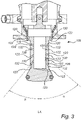
- a system 200 including a retractable cleaning apparatus 100 for spray cleaning of pipes 202 or vessels 204.
- the retractable cleaning apparatus 100 includes a rotatable spray head 102 which is configured to spray the interior 206 of the pipes 202 or vessels 204 with a cleaning liquid L.
- the retractable cleaning apparatus 100 is depicted in a cleaning position CP in which position the rotatable spray head 102 is moved into and present in the depicted pipe 202.
- the size, i.e. the diameter of the pipe 202 may vary greatly.
- the diameter of the pipe 202 may for instance be 150, 300, 500 or 1000 mm to give a few non-limiting examples. It is to be understood that the pipe 202 may be replaced by any type of vessel 204.
- Fig. 1b the retractable cleaning apparatus 100 is depicted in a retracted position RP in which position the rotatable spray head 102 is moved out of the depicted pipe 202.
- the end portion of the rotatable spray head 102 is the sole part of the retractable cleaning apparatus 100 which is visible from the interior 206 of the depicted pipe 202.
- the end portion of the rotatable spray head 102 seals the interior 206 of the depicted pipe 202 in a fluid tight manner in the retracted position RP.
- the rotatable spray head 102 is shown in phantom in the retracted position RP.
- the rotatable spray head 102 is linearly movable between the retracted position RP and the cleaning position CP along the longitudinal axis LA of the rotatable spray head 102.
- the rotatable spray head 102 is rotatable about the longitudinal axis LA of the rotatable spray head 102 independent of a flow of the cleaning liquid L.
- the rotatable spray head 102 is rotatable by a drive mechanism that does not depend on any flow of the cleaning liquid L.
- the rotatable spray head 102 is driven independently of any flow of the cleaning liquid L.
- the rotatable spray head 102 is rotatable irrespective of if there is a flow of cleaning liquid L or not.
- the rotatable spray head 102 is rotatable independent of a pressure of the cleaning liquid L.
- the rotatable spray head 102 is rotatable independent of a flow, such as a mass flow or volume flow, of the cleaning liquid L.
- the rotatable spray head 102 is configured for reciprocating rotation about the longitudinal axis LA of the rotatable spray head 102.
- the rotatable spray head 102 is configured to rotate back and forth about the longitudinal axis LA of the rotatable spray head 102.
- the rotatable spray head 102 is configured to rotate in a first direction, e.g. clockwise, and then reverse its direction to rotate in a second opposite direction, e.g. counterclockwise, repeatedly such that a reciprocating rotation about the longitudinal axis LA of the rotatable spray head 102 is achieved.
- the rotatable spray head 102 is rotatable with an angular velocity within a range of 0.1 - 1.3 radians per second. This angular velocity corresponds roughly to an instantaneous rotational speed of 0.95 - 12.4 rpms.
- the rotatable spray head 102 may be rotatable with other angular velocities.
- FIG. 2 here is conceptually depicted the system 200 including the retractable cleaning apparatus 100 of Figs. 1a and 1b .
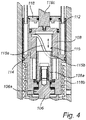
- a cross sectional view of the retractable cleaning apparatus 100 along the line B-B of Fig. 1a is shown.
- the rotatable spray head 102 is in the cleaning position CP.
- the design of the depicted rotatable spray head 102 is shown in greater detail in Fig. 3 to which reference is also made.
- the rotatable spray head 102 of the depicted retractable cleaning apparatus 100 of Figs. 1a , 1b and 2 is as described linearly movable between a retracted position RP and a cleaning position CP along the longitudinal axis LA of the rotatable spray head 102.
- the movement between the retracted position RP and a cleaning position CP is achieved by a pneumatically driven linearly movable second piston 118.
- the linearly movable second piston 118 is mechanically coupled to the rotatable spray head 102 via a pneumatically driven unit 104 which will be described in greater detail below.
- the depicted linearly movable second piston 118 is operated by introducing pressurized air above the linearly movable second piston 118 in the piston chamber 118a.
- pressurized air is introduced above the linearly movable second piston 118 in the piston chamber 118a
- the linearly movable second piston 118 is pushed downwards in Fig. 2 , resulting in that the rotatable spray head 102 is moved to the cleaning position CP.
- the rotatable spray head 102 is moved to the retracted position RP by evacuating or draining air form the piston chamber 118a, resulting in that the spring 118b pushes the linearly movable second piston 118 upwards in Fig. 2 .
- the spring 118b pushes the linearly movable second piston 118 upwards in Fig. 2 .
- the linearly movable second piston 118 is formed of an upper part of the pneumatically driven unit 104. Hence, when the linearly movable second piston 118 is moved, a significant part of the retractable cleaning apparatus 100 including the pneumatically driven unit 104 and the rotatable spray head 102 is moved along the longitudinal axis LA of the rotatable spray head 102.
- the linearly movable second piston 118 may be hydraulically driven by a pressurized hydraulic fluid such as hydraulic oil.
- the position of the rotatable spray head 102 along the longitudinal axis LA of the rotatable spray head 102 is monitored by a sensor located in a control device 150 of the retractable cleaning apparatus 100.
- the control device 150 includes the sensor and a control unit 152 in the depicted retractable cleaning apparatus 100.
- the sensor is connected to the control unit 152.
- the sensor is configured to sense the position of the member 118c which is moved inside of the control device 150 correspondingly to a movement of the rotatable spray head 102 along the longitudinal axis LA of the rotatable spray head 102.
- the control unit 152 is configured to control the introduction and removal of pressurized air above the linearly movable second piston 118 in the piston chamber 118a.
- the control unit 152 is configured to control the movement of the rotatable spray head 102 along the longitudinal axis LA of the rotatable spray head 102.
- the rotatable spray head 102 is made to rotate about the longitudinal axis LA of the rotatable spray head 102 by the pneumatically driven unit 104.
- the pneumatically driven unit 104 is configured to convert a reciprocatingly translational drive movement DM to a reciprocatingly rotational movement RRM of the rotatable spray head 102.
- the depicted pneumatically driven unit 104 is driven by pressurized air.
- the rotatable spray head 102 is coupled to a rotatable member 106, which when rotated causes the rotatable spray head 102 to rotate correspondingly.
- the pneumatically or hydraulically driven unit 104 causes the rotatable spray head 102 to rotate reciprocatingly.
- the pneumatically or hydraulically driven unit 104 includes a linearly movable first piston 108 and is configured to convert a reciprocatingly translational drive movement DM of the linearly movable first piston 108 to a reciprocatingly rotational movement RRM of the rotatable member 106 and the rotatable spray head 102.
- the linearly movable first piston 108 is coupled to the is mechanically coupled to the rotatable member 106 via the intermediate member 108a.
- the intermediate member 108a is coupled to the rotatable member 106 such that the intermediate member 108a and the rotatable member 106 corotates.
- the intermediate member 108a and the rotatable member 106 may as an alternative be integrally formed.
- the rotatable member 106 is held static with respect to the longitudinal axis LA of the rotatable spray head 102 by means of a rotationally symmetric protrusion 106a provided thereon.
- a bearing or similar may be provided to reduce friction when rotating the rotatable member 106.
- the intermediate member 108a coupled to the rotatable member 106 is provided with external threads 116a.
- the linearly movable first piston 108 is provided with corresponding internal threads 116b.
- the respective threads 116a, 116b are meshed, resulting in that a reciprocatingly translational drive movement DM of the linearly movable first piston 108 is converted to a reciprocatingly rotational movement RRM of the rotatable member 106 and the rotatable spray head 102.
- the rotatable member 106 and the intermediate member 108a may be differently designed and may for instance be formed as a shaft, a cylinder, a hollow member to give a few non-limiting examples.
- the linearly movable first piston 108 is arranged in a piston chamber 110.
- the piston chamber 110 is provided with a first fluid port 112 configured to pass a fluid into or out of the piston chamber 110 on a first side of the linearly movable first piston 108, such that the linearly movable first piston 108 is linearly moved in the piston chamber 110 in response to passing fluid into or out of the piston chamber 110 through the first fluid port 112.
- An inner surface of the piston chamber 110 may be provided with a longitudinal protrusion which may engage a corresponding recess provided on the linearly movable first piston 108.
- the first fluid port 112 is provided such that pressurized air may be passed into or out of the piston chamber 110 on an upper side of the linearly movable first piston 108.
- pressurized air may be passed into or out of the piston chamber 110 on an upper side of the linearly movable first piston 108.
- the linearly movable first piston 108 will move downwards in Fig. 2 , resulting in a rotational movement of the rotatable member 106 and the rotatable spray head 102.
- pressurized air is removed from the piston chamber 110 through the first fluid port 112 the linearly movable first piston 108 may move upwards in Fig. 2 , resulting in an opposite rotational movement of the rotatable member 106 and the rotatable spray head 102.
- the piston chamber 110 is provided with a second fluid port 114 configured to pass fluid into or out of the piston chamber 110 on a second side of the linearly movable first piston 108, such that the linearly movable first piston 108 is linearly moved in the piston chamber 110 in response to passing fluid into or out of the piston chamber 110 through the second fluid port 114.
- the second fluid port 114 is provided such that pressurized air may be passed into or out of the piston chamber 110 on lower side of the linearly movable first piston 108.
- pressurized air may be passed into or out of the piston chamber 110 on lower side of the linearly movable first piston 108.
- the linearly movable first piston 108 will move upwards in Fig. 2 , resulting in a rotational movement of the rotatable member 106 and the rotatable spray head 102.
- pressurized air is removed from the piston chamber 110 through the second fluid port 114 the linearly movable first piston 108 may move downwards in Fig. 2 , resulting in an opposite rotational movement of the rotatable member 106 and the rotatable spray head 102.
- the linearly movable first piston 108 is caused to move reciprocatingly by alternatingly introducing and removing pressurized air through the first fluid port 112 and the second fluid port 114.
- either side of the linearly movable first piston 108 is alternatingly pressurized.
- the introduction and removal of pressurized air is controlled by means of valves which are controlled by the control unit 152.
- the rotation speed of the rotatable spray head 102 may consequently be controlled by controlling the speed by which pressurized air is introduced and removed through the first fluid port 112 and the second fluid port 114.
- the linearly movable first piston 108 may be spring loaded such that a spring pushes the linearly movable first piston 108 back upon removal of pressurized air through the single fluid port.
- each rotational movement of the reciprocatingly rotational movement RRM is less than 8 radians.
- the maximum rotational movement of a reciprocating rotational movement is determined by how much the rotatable member 106 is rotated during a full stoke of the linearly movable first piston 108.
- the linearly movable first piston 108 may be made to reciprocate up and down at a certain point of its stroke length.
- the maximum rotational movement of a reciprocating rotational movement may be tailored by tailoring the pitch of the threads 116a, 116b.
- the cam arrangement 115 includes a helical cam groove 115a and a cam protrusion 115b which follows the cam groove 115a.
- the depicted cam groove 115a is provided on the linearly movable first piston 108.
- the depicted cam protrusion 115b is provided on the intermediate member 108a.
- the cam groove 115a may correspondingly be provided on the intermediate member 108a and the cam protrusion 115b on the linearly movable first piston 108.
- the maximum rotational movement of a reciprocating rotational movement is in this case determined by the pitch of the cam grove 115a, i.e. how much the rotatable member 106 is rotated during a full stoke of the linearly movable first piston 108.
- the rotatable spray head 102 may be made to rotate about the longitudinal axis LA of the rotatable spray head 102 by a hydraulically driven unit in a corresponding manner to what has been described above.
- the hydraulically driven unit may then be driven by a pressurized hydraulic fluid such as hydraulic oil.
- the rotatable spray head 102 of the depicted retractable cleaning apparatus 100 is provided with a plurality of nozzle channels 120.
- the depicted nozzle channels 120 are formed as bores in the rotatable spray head 102.
- Each nozzle orifice 122 typically has a diameter within a range of 1 - 3 mm. Other diameters may be used in order to tailor the spray behavior of the retractable cleaning apparatus 100. For instance, 0.5 - 5 mm may be used.
- the nozzle orifices 122 may have other shapes than circular.
- the nozzle orifices 122 may be elongated, square shaped, star shaped, Z-shaped to give a few non-limiting examples.
- all nozzle channels 120 are extending in a radial direction of the rotatable spray head 102. This means that all nozzle channels 120 are extending in a direction coinciding with an arbitrary radial plane of the longitudinal axis LA of the rotatable spray head 102. By this arrangement, no rotational reactional force is exhibited on the rotatable spray head 102 by a flow of cleaning liquid L through the nozzle channels 120.
- Not all nozzle channels 120 need to extend in a radial direction of the rotatable spray head 102. However, preferably, a majority of the nozzle channels 120 are to extend in a radial direction of the rotatable spray head 102. In fact, no nozzle channel 120 need to extend in a radial direction of the rotatable spray head 102. In other words, some or all nozzle channels 120 may be inclined with respect to any radial plane of the longitudinal axis LA of the rotatable spray head 102.
- the nozzle channels 120 extend with different angles ⁇ , ⁇ with respect to the longitudinal axis LA of the rotatable spray head 102.
- the fact that the nozzle channels 120 extend with different ⁇ , ⁇ angles with respect to the longitudinal axis LA of the rotatable spray head 102 brings about that an efficient spray cleaning pattern with a desirable coverage of the interior 206 of the pipes 202 or vessel 204 at hand may be achieved.
- a plurality of spray jets sprayed at different angles and forming a spray pattern may be achieved.
- At least two of the nozzle channels 120 may extend at different angles ⁇ , ⁇ with respect to the longitudinal axis LA of the rotatable spray head 102. However, all nozzle channels 120 may extend at the same angle with respect to the longitudinal axis LA of the rotatable spray head 102.
- the depicted rotatable spray head 102 of Fig. 3 is provided with 12 nozzle channels 120, each terminating in a nozzle orifice 122.
- the nozzle channels 120 are arranged along two lines of the rotatable spray head 102. The lines being opposite to each other and parallel to the longitudinal axis LA of the rotatable spray head 102.
- the rotatable spray head 102 is provided with 4-20 nozzle channels 120, more preferably with 10-14 nozzle channels 120, each terminating in a nozzle orifice 122.
- a first measure is typically to move the rotatable spray head 102 from the retracted position RP to the cleaning position CP along a longitudinal axis LA of the rotatable spray head 102.
- the rotatable spray head 102 is made to rotate reciprocatingly as have been described above.
- a cleaning liquid L is introduced through the opening 130 of flange 132. The cleaning liquid L is then following the path indicated with arrows marked L in Fig.
- the cleaning liquid L is typically provided at a pressure in a range of 2 - 8 bars.
- the flow of the cleaning liquid L is turned off, i.e. cleaning liquid L is no longer introduced through the opening 130 of flange 132.
- a spray pattern is no longer provided by the rotatable spray head 102.
- the reciprocatingly rotational movement RRM of the spray head is turned off by stopping the reciprocatingly translational drive movement DM of the linearly movable first piston 108.
- the rotatable spray head 102 is then moved from the cleaning position CP to the retracted position RP along the longitudinal axis LA of the rotatable spray head 102, such that the end portion of the rotatable spray head 102 is the sole part of the retractable cleaning apparatus 100 that is visible from the interior 206 of the pipes 202 or vessels 204.
- the end portion of the rotatable spray head 102 is generally flush with the walls of the pipes 202 or vessels 204. In other words, the rotatable spray head 102 is no longer projecting into the interior 206 of the pipes 202 or vessels 204.
Landscapes
- Cleaning In General (AREA)
- Nozzles (AREA)
Priority Applications (5)
| Application Number | Priority Date | Filing Date | Title |
|---|---|---|---|
| EP20210720.7A EP4005686A1 (fr) | 2020-11-30 | 2020-11-30 | Appareil et système de nettoyage rétractable |
| CN202180080077.2A CN116528989A (zh) | 2020-11-30 | 2021-11-29 | 可缩回清洁设备和系统 |
| PCT/EP2021/083367 WO2022112557A1 (fr) | 2020-11-30 | 2021-11-29 | Appareil et système de nettoyage rétractable |
| EP21823508.3A EP4251334A1 (fr) | 2020-11-30 | 2021-11-29 | Appareil et système de nettoyage rétractable |
| US18/253,410 US20230415188A1 (en) | 2020-11-30 | 2021-11-29 | Retractable cleaning apparatus and system |
Applications Claiming Priority (1)
| Application Number | Priority Date | Filing Date | Title |
|---|---|---|---|
| EP20210720.7A EP4005686A1 (fr) | 2020-11-30 | 2020-11-30 | Appareil et système de nettoyage rétractable |
Publications (1)
| Publication Number | Publication Date |
|---|---|
| EP4005686A1 true EP4005686A1 (fr) | 2022-06-01 |
Family
ID=73646240
Family Applications (2)
| Application Number | Title | Priority Date | Filing Date |
|---|---|---|---|
| EP20210720.7A Pending EP4005686A1 (fr) | 2020-11-30 | 2020-11-30 | Appareil et système de nettoyage rétractable |
| EP21823508.3A Pending EP4251334A1 (fr) | 2020-11-30 | 2021-11-29 | Appareil et système de nettoyage rétractable |
Family Applications After (1)
| Application Number | Title | Priority Date | Filing Date |
|---|---|---|---|
| EP21823508.3A Pending EP4251334A1 (fr) | 2020-11-30 | 2021-11-29 | Appareil et système de nettoyage rétractable |
Country Status (4)
| Country | Link |
|---|---|
| US (1) | US20230415188A1 (fr) |
| EP (2) | EP4005686A1 (fr) |
| CN (1) | CN116528989A (fr) |
| WO (1) | WO2022112557A1 (fr) |
Cited By (1)
| Publication number | Priority date | Publication date | Assignee | Title |
|---|---|---|---|---|
| EP4321261A1 (fr) * | 2022-08-12 | 2024-02-14 | Goodrich Corporation | Téton de rinçage |
Citations (5)
| Publication number | Priority date | Publication date | Assignee | Title |
|---|---|---|---|---|
| EP0295325A1 (fr) * | 1987-06-19 | 1988-12-21 | Chemap AG | Dispositif de nettoyage pour des récipients utilisés dans des procédés relevant de la biotechnologie et dans des procédés industriels |
| US5706842A (en) * | 1995-03-29 | 1998-01-13 | The United States Of America As Represented By The Administrator Of The National Aeronautics And Space Administration | Balanced rotating spray tank and pipe cleaning and cleanliness verification system |
| US20010017323A1 (en) * | 2000-02-16 | 2001-08-30 | Roland Feller | Cleaning nozzle |
| DE202004012949U1 (de) | 2004-08-18 | 2004-11-18 | Tuchenhagen Gmbh | Vorrichtung zur Innenreinigung von Behältern |
| WO2014092657A1 (fr) * | 2012-12-12 | 2014-06-19 | Brinox, D.O.O. | Tête de lavage à rétraction à auto-nettoyage avec entraînement pneumatique |
-
2020
- 2020-11-30 EP EP20210720.7A patent/EP4005686A1/fr active Pending
-
2021
- 2021-11-29 WO PCT/EP2021/083367 patent/WO2022112557A1/fr active Application Filing
- 2021-11-29 EP EP21823508.3A patent/EP4251334A1/fr active Pending
- 2021-11-29 US US18/253,410 patent/US20230415188A1/en active Pending
- 2021-11-29 CN CN202180080077.2A patent/CN116528989A/zh active Pending
Patent Citations (5)
| Publication number | Priority date | Publication date | Assignee | Title |
|---|---|---|---|---|
| EP0295325A1 (fr) * | 1987-06-19 | 1988-12-21 | Chemap AG | Dispositif de nettoyage pour des récipients utilisés dans des procédés relevant de la biotechnologie et dans des procédés industriels |
| US5706842A (en) * | 1995-03-29 | 1998-01-13 | The United States Of America As Represented By The Administrator Of The National Aeronautics And Space Administration | Balanced rotating spray tank and pipe cleaning and cleanliness verification system |
| US20010017323A1 (en) * | 2000-02-16 | 2001-08-30 | Roland Feller | Cleaning nozzle |
| DE202004012949U1 (de) | 2004-08-18 | 2004-11-18 | Tuchenhagen Gmbh | Vorrichtung zur Innenreinigung von Behältern |
| WO2014092657A1 (fr) * | 2012-12-12 | 2014-06-19 | Brinox, D.O.O. | Tête de lavage à rétraction à auto-nettoyage avec entraînement pneumatique |
Cited By (1)
| Publication number | Priority date | Publication date | Assignee | Title |
|---|---|---|---|---|
| EP4321261A1 (fr) * | 2022-08-12 | 2024-02-14 | Goodrich Corporation | Téton de rinçage |
Also Published As
| Publication number | Publication date |
|---|---|
| WO2022112557A1 (fr) | 2022-06-02 |
| CN116528989A (zh) | 2023-08-01 |
| EP4251334A1 (fr) | 2023-10-04 |
| US20230415188A1 (en) | 2023-12-28 |
Similar Documents
| Publication | Publication Date | Title |
|---|---|---|
| US10960415B1 (en) | Spray nozzle and method | |
| EP0892685B1 (fr) | Appareil commande par ordinateur et procede de nettoyage de cuves ou reservoirs | |
| US20230415188A1 (en) | Retractable cleaning apparatus and system | |
| US10722913B2 (en) | Liquid ejection apparatus | |
| US9987668B2 (en) | Liquid ejection system with nozzle having two outlets | |
| US11964313B2 (en) | Reaction force nozzle | |
| US3267944A (en) | Spray device for dishwashing apparatus | |
| US3595256A (en) | Vessel-cleaning apparatus | |
| EP0384690B1 (fr) | Dispositif de nettoyage pour des conteneurs | |
| US3255970A (en) | Tank cleaning apparatus | |
| US2556517A (en) | Nozzle for producing an intermittent jet of gas or liquid | |
| US20120187219A1 (en) | Rotary pulsating valve and method for discharging fluid | |
| EP3922369B1 (fr) | Appareil pour le lavage de récipients | |
| EP1472020B1 (fr) | Appareil de lavage pour reservoirs | |
| CN215481274U (zh) | 一种具有模具清洁功能的多工位腐蚀机 | |
| US4296886A (en) | Shower fittings | |
| AU2020364972A1 (en) | Cleaning in place robotic nozzle system | |
| WO1996020791A1 (fr) | Ajutage | |
| US20170361341A1 (en) | Rotor nozzle for a high-pressure cleaning apparatus | |
| RU2700602C1 (ru) | Устройство для мойки полых изделий | |
| GB2257619A (en) | A tank washer | |
| KR102699975B1 (ko) | 관 세척장치 | |
| SU1662713A1 (ru) | Устройство дл струйной очистки изделий | |
| SU880520A1 (ru) | Устройство дл мойки емкостей | |
| RU2147085C1 (ru) | Вихревой струйный аппарат |
Legal Events
| Date | Code | Title | Description |
|---|---|---|---|
| PUAI | Public reference made under article 153(3) epc to a published international application that has entered the european phase |
Free format text: ORIGINAL CODE: 0009012 |
|
| STAA | Information on the status of an ep patent application or granted ep patent |
Free format text: STATUS: THE APPLICATION HAS BEEN PUBLISHED |
|
| AK | Designated contracting states |
Kind code of ref document: A1 Designated state(s): AL AT BE BG CH CY CZ DE DK EE ES FI FR GB GR HR HU IE IS IT LI LT LU LV MC MK MT NL NO PL PT RO RS SE SI SK SM TR |
|
| STAA | Information on the status of an ep patent application or granted ep patent |
Free format text: STATUS: REQUEST FOR EXAMINATION WAS MADE |
|
| 17P | Request for examination filed |
Effective date: 20221201 |
|
| RBV | Designated contracting states (corrected) |
Designated state(s): AL AT BE BG CH CY CZ DE DK EE ES FI FR GB GR HR HU IE IS IT LI LT LU LV MC MK MT NL NO PL PT RO RS SE SI SK SM TR |