EP4005495A1 - Ultrasonic diagnosis device and control method for ultrasonic diagnosis device - Google Patents
Ultrasonic diagnosis device and control method for ultrasonic diagnosis device Download PDFInfo
- Publication number
- EP4005495A1 EP4005495A1 EP20843651.9A EP20843651A EP4005495A1 EP 4005495 A1 EP4005495 A1 EP 4005495A1 EP 20843651 A EP20843651 A EP 20843651A EP 4005495 A1 EP4005495 A1 EP 4005495A1
- Authority
- EP
- European Patent Office
- Prior art keywords
- ultrasound
- blood vessel
- rate
- image
- insertion object
- Prior art date
- Legal status (The legal status is an assumption and is not a legal conclusion. Google has not performed a legal analysis and makes no representation as to the accuracy of the status listed.)
- Pending
Links
- 238000000034 method Methods 0.000 title claims abstract description 36
- 238000003745 diagnosis Methods 0.000 title description 7
- 238000002604 ultrasonography Methods 0.000 claims abstract description 244
- 238000003780 insertion Methods 0.000 claims abstract description 166
- 230000037431 insertion Effects 0.000 claims abstract description 166
- 210000004204 blood vessel Anatomy 0.000 claims abstract description 148
- 238000010191 image analysis Methods 0.000 claims abstract description 66
- 230000005540 biological transmission Effects 0.000 claims abstract description 62
- 238000012545 processing Methods 0.000 claims description 43
- 238000006073 displacement reaction Methods 0.000 claims description 21
- 210000001367 artery Anatomy 0.000 claims description 16
- 210000003462 vein Anatomy 0.000 claims description 15
- 230000003247 decreasing effect Effects 0.000 claims description 13
- 239000000523 sample Substances 0.000 description 18
- 238000006243 chemical reaction Methods 0.000 description 9
- 230000033001 locomotion Effects 0.000 description 9
- 238000010586 diagram Methods 0.000 description 8
- 230000003321 amplification Effects 0.000 description 5
- 238000003199 nucleic acid amplification method Methods 0.000 description 5
- 230000007423 decrease Effects 0.000 description 4
- 238000001514 detection method Methods 0.000 description 4
- 238000013135 deep learning Methods 0.000 description 3
- 238000003384 imaging method Methods 0.000 description 3
- 238000010801 machine learning Methods 0.000 description 3
- 230000002093 peripheral effect Effects 0.000 description 3
- 238000005401 electroluminescence Methods 0.000 description 2
- 229910052451 lead zirconate titanate Inorganic materials 0.000 description 2
- 238000012986 modification Methods 0.000 description 2
- 230000004048 modification Effects 0.000 description 2
- 230000001902 propagating effect Effects 0.000 description 2
- 230000000007 visual effect Effects 0.000 description 2
- BQCIDUSAKPWEOX-UHFFFAOYSA-N 1,1-Difluoroethene Chemical compound FC(F)=C BQCIDUSAKPWEOX-UHFFFAOYSA-N 0.000 description 1
- FYYHWMGAXLPEAU-UHFFFAOYSA-N Magnesium Chemical compound [Mg] FYYHWMGAXLPEAU-UHFFFAOYSA-N 0.000 description 1
- 238000004364 calculation method Methods 0.000 description 1
- 239000000919 ceramic Substances 0.000 description 1
- 239000012141 concentrate Substances 0.000 description 1
- 238000013527 convolutional neural network Methods 0.000 description 1
- 238000012937 correction Methods 0.000 description 1
- 239000013078 crystal Substances 0.000 description 1
- 230000001934 delay Effects 0.000 description 1
- 230000010365 information processing Effects 0.000 description 1
- HFGPZNIAWCZYJU-UHFFFAOYSA-N lead zirconate titanate Chemical compound [O-2].[O-2].[O-2].[O-2].[O-2].[Ti+4].[Zr+4].[Pb+2] HFGPZNIAWCZYJU-UHFFFAOYSA-N 0.000 description 1
- 239000004973 liquid crystal related substance Substances 0.000 description 1
- 229910052749 magnesium Inorganic materials 0.000 description 1
- 239000011777 magnesium Substances 0.000 description 1
- 230000001537 neural effect Effects 0.000 description 1
- 229920000642 polymer Polymers 0.000 description 1
- 229920000131 polyvinylidene Polymers 0.000 description 1
- 239000007787 solid Substances 0.000 description 1
- 230000002792 vascular Effects 0.000 description 1
Images




Classifications
-
- A—HUMAN NECESSITIES
- A61—MEDICAL OR VETERINARY SCIENCE; HYGIENE
- A61B—DIAGNOSIS; SURGERY; IDENTIFICATION
- A61B8/00—Diagnosis using ultrasonic, sonic or infrasonic waves
- A61B8/08—Clinical applications
- A61B8/0833—Clinical applications involving detecting or locating foreign bodies or organic structures
- A61B8/0841—Clinical applications involving detecting or locating foreign bodies or organic structures for locating instruments
-
- A—HUMAN NECESSITIES
- A61—MEDICAL OR VETERINARY SCIENCE; HYGIENE
- A61B—DIAGNOSIS; SURGERY; IDENTIFICATION
- A61B8/00—Diagnosis using ultrasonic, sonic or infrasonic waves
- A61B8/44—Constructional features of the ultrasonic, sonic or infrasonic diagnostic device
- A61B8/4483—Constructional features of the ultrasonic, sonic or infrasonic diagnostic device characterised by features of the ultrasound transducer
- A61B8/4488—Constructional features of the ultrasonic, sonic or infrasonic diagnostic device characterised by features of the ultrasound transducer the transducer being a phased array
-
- A—HUMAN NECESSITIES
- A61—MEDICAL OR VETERINARY SCIENCE; HYGIENE
- A61B—DIAGNOSIS; SURGERY; IDENTIFICATION
- A61B8/00—Diagnosis using ultrasonic, sonic or infrasonic waves
- A61B8/08—Clinical applications
- A61B8/0833—Clinical applications involving detecting or locating foreign bodies or organic structures
- A61B8/085—Clinical applications involving detecting or locating foreign bodies or organic structures for locating body or organic structures, e.g. tumours, calculi, blood vessels, nodules
-
- A—HUMAN NECESSITIES
- A61—MEDICAL OR VETERINARY SCIENCE; HYGIENE
- A61B—DIAGNOSIS; SURGERY; IDENTIFICATION
- A61B8/00—Diagnosis using ultrasonic, sonic or infrasonic waves
- A61B8/08—Clinical applications
- A61B8/0891—Clinical applications for diagnosis of blood vessels
-
- A—HUMAN NECESSITIES
- A61—MEDICAL OR VETERINARY SCIENCE; HYGIENE
- A61B—DIAGNOSIS; SURGERY; IDENTIFICATION
- A61B8/00—Diagnosis using ultrasonic, sonic or infrasonic waves
- A61B8/46—Ultrasonic, sonic or infrasonic diagnostic devices with special arrangements for interfacing with the operator or the patient
- A61B8/461—Displaying means of special interest
-
- A—HUMAN NECESSITIES
- A61—MEDICAL OR VETERINARY SCIENCE; HYGIENE
- A61B—DIAGNOSIS; SURGERY; IDENTIFICATION
- A61B8/00—Diagnosis using ultrasonic, sonic or infrasonic waves
- A61B8/46—Ultrasonic, sonic or infrasonic diagnostic devices with special arrangements for interfacing with the operator or the patient
- A61B8/461—Displaying means of special interest
- A61B8/463—Displaying means of special interest characterised by displaying multiple images or images and diagnostic data on one display
-
- A—HUMAN NECESSITIES
- A61—MEDICAL OR VETERINARY SCIENCE; HYGIENE
- A61B—DIAGNOSIS; SURGERY; IDENTIFICATION
- A61B8/00—Diagnosis using ultrasonic, sonic or infrasonic waves
- A61B8/52—Devices using data or image processing specially adapted for diagnosis using ultrasonic, sonic or infrasonic waves
-
- A—HUMAN NECESSITIES
- A61—MEDICAL OR VETERINARY SCIENCE; HYGIENE
- A61B—DIAGNOSIS; SURGERY; IDENTIFICATION
- A61B8/00—Diagnosis using ultrasonic, sonic or infrasonic waves
- A61B8/54—Control of the diagnostic device
-
- A—HUMAN NECESSITIES
- A61—MEDICAL OR VETERINARY SCIENCE; HYGIENE
- A61B—DIAGNOSIS; SURGERY; IDENTIFICATION
- A61B8/00—Diagnosis using ultrasonic, sonic or infrasonic waves
- A61B8/56—Details of data transmission or power supply
- A61B8/565—Details of data transmission or power supply involving data transmission via a network
Definitions
- the present invention relates to an ultrasound diagnostic apparatus, and a control method of the ultrasound diagnostic apparatus which display an insertion object to be inserted into a blood vessel of a subject, on an ultrasound image.
- an ultrasound diagnostic apparatus has been known as an apparatus for obtaining an image of the inside of a subject.
- the ultrasound diagnostic apparatus generally comprises an ultrasound probe comprising a transducer array in which a plurality of ultrasonic transducers are arranged.
- an ultrasound beam is transmitted toward the inside of the subject from the transducer array and an ultrasound echo from the subject is received by the transducer array so that an electric signal corresponding to the ultrasound echo is acquired.
- the ultrasound diagnostic apparatus electrically processes the obtained electric signal to generate an ultrasound image of the corresponding site of the subject.
- a procedure of inserting an insertion object such as a so-called puncture needle and a catheter into the blood vessel of the subject while observing the inside of the subject using such an ultrasound diagnostic apparatus is known.
- the frame rate at which the ultrasound image is generated is high so that an operator can grasp the motion of the insertion object and the blood vessel.
- JP2010-88486A an ultrasound diagnostic apparatus has been developed which automatically increases the frame rate at which the ultrasound image is generated, using the detection of the insertion object in the ultrasound image as a trigger.
- the frame rate is changed according to a relative positional relationship between the insertion object and the blood vessel, but the operator needs to concentrate on the procedure of inserting the insertion object into the blood vessel, and therefore, it is difficult to manually change the frame rate during the ultrasound diagnosis in some cases.
- the present invention has been made in order to solve such a problem in the related art, and an object thereof is to provide an ultrasound diagnostic apparatus, and a control method of the ultrasound diagnostic apparatus which can automatically adjust the frame rate to an appropriate rate according to a relative positional relationship between an insertion object and a blood vessel.
- an ultrasound diagnostic apparatus that displays an insertion object to be inserted into a blood vessel of a subject on an ultrasound image
- the ultrasound diagnostic apparatus comprises a transducer array; a transmission and reception circuit that causes the transducer array to transmit an ultrasound beam toward the subject, and processes a reception signal output from the transducer array that has received an ultrasound echo from the subject to generate a sound ray signal; an image generation unit that generates the ultrasound image on the basis of the sound ray signal generated by the transmission and reception circuit; an image analysis unit that detects the blood vessel and the insertion object by analyzing the ultrasound image generated by the image generation unit; and a device control unit that controls the transmission and reception circuit such that a frame rate at which the ultrasound image is generated by the image generation unit is adjusted, on the basis of a relative positional relationship between the blood vessel and the insertion object detected by the image analysis unit.
- the device control unit controls the transmission and reception circuit such that the frame rate at which the ultrasound image is generated by the image generation unit is set to a predetermined first rate in a case where a distance between a distal end of the insertion object and the blood vessel detected by the image analysis unit exceeds a predetermined distance threshold value, and the frame rate is switched to a second rate higher than the first rate in a case where the distance between the distal end of the insertion object and the blood vessel detected by the image analysis unit is equal to or less than the predetermined distance threshold value.
- the device control unit controls the transmission and reception circuit such that the frame rate is set to a third rate in a case where the distal end of the insertion object detected by the image analysis unit is inserted into the blood vessel and a displacement amount of the distal end of the insertion object in the blood vessel within a predetermined time is equal to or less than a displacement amount threshold value.
- the third rate may be a rate equal to the first rate or lower than the first rate.
- the device control unit controls the transmission and reception circuit such that in a case where the frame rate is the third rate, a resolution of the ultrasound image is higher than in a case where the frame rate is the second rate.
- the third rate may be a rate equal to the second rate or higher than the second rate.
- the image analysis unit may measure any one of a diameter, a radius, a length of an outer circumference, or an area of the detected blood vessel, and the device control unit may control the transmission and reception circuit such that the second rate becomes a higher rate as the diameter, the radius, the length of the outer circumference, or the area of the blood vessel measured by the image analysis unit is decreased.
- the image analysis unit may measure a distance between the vein and the artery, and the device control unit may control the transmission and reception circuit such that the second rate becomes a higher rate as the distance between the vein and the artery measured by the image analysis unit is shorter.
- the ultrasound diagnostic apparatus may further comprise a display device that displays the ultrasound image generated by the image generation unit; and a highlighting unit that highlights the blood vessel and the insertion object detected by the image analysis unit, on the display device.
- a control method of an ultrasound diagnostic apparatus is a control method of an ultrasound diagnostic apparatus that displays an insertion object to be inserted into a blood vessel of a subject on an ultrasound image, and the control method comprises causing a transducer array to transmit an ultrasound beam toward the subject, and processing a reception signal output from the transducer array that has received an ultrasound echo from the subj ect to generate a sound ray signal; generating the ultrasound image on the basis of the generated sound ray signal; detecting the blood vessel and the insertion object by analyzing the generated ultrasound image; and adjusting a frame rate at which the ultrasound image is generated, on the basis of a relative positional relationship between the detected blood vessel and the detected insertion object.
- the ultrasound diagnostic apparatus comprises the transmission and reception circuit that causes the transducer array to transmit the ultrasound beam toward the subject, and processes the reception signal output from the transducer array that has received the ultrasound echo from the subject to generate the sound ray signal; the image generation unit that generates the ultrasound image on the basis of the sound ray signal generated by the transmission and reception circuit; the image analysis unit that detects the blood vessel and the insertion object by analyzing the ultrasound image generated by the image generation unit; and the device control unit that controls the transmission and reception circuit such that the frame rate at which the ultrasound image is generated by the image generation unit is adjusted, on the basis of the relative positional relationship between the blood vessel and the insertion object detected by the image analysis unit, it is possible to automatically adjust the frame rate to an appropriate rate according to the relative positional relationship between the insertion object and the blood vessel.
- a numerical range represented using “to” means a range including the numerical values before and after “to” as a lower limit value and an upper limit value.
- the terms “perpendicular” and “parallel” include a range of errors allowed in the technical field to which the present invention belongs.
- the terms “perpendicular” and “parallel” mean a range less than ⁇ 10 degrees with respect to the strict perpendicular or parallel, and the error with respect to the strict perpendicular or parallel is preferably 5 degrees or less, and more preferably 3 degrees or less.
- the terms “same” and “identical” include an error range generally allowed in the technical field. Further, in a case of referring to “all”, “any”, or “whole surface”, the term includes an error range generally allowed in the technical field in addition to a case of 100%, and includes, for example, a case of 99% or more, a case of 95% or more, or a case of 90% or more.
- Fig. 1 illustrates a configuration of an ultrasound diagnostic apparatus 1 according to a first embodiment of the present invention.
- the ultrasound diagnostic apparatus 1 comprises a transducer array 2, and each of a transmission circuit 3 and a reception circuit 4 is connected to the transducer array 2.
- the transmission circuit 3 and the reception circuit 4 constitute a transmission and reception circuit 5, and an image generation unit 6, a display control unit 7, and a display device 8 are sequentially connected to the reception circuit 4.
- An image analysis unit 9 is connected to the image generation unit 6.
- a device control unit 13 is connected to the transmission and reception circuit 5, the image generation unit 6, the display control unit 7, and the image analysis unit 9, and an input device 14 and a storage unit 15 are connected to the device control unit 13.
- the device control unit 13 and the storage unit 15 are connected so as to exchange information bidirectionally.
- the transducer array 2 and the transmission and reception circuit 5 are included in an ultrasound probe 21. Further, the image generation unit 6, the display control unit 7, the image analysis unit 9, and the device control unit 13 constitute a processor 22 for the ultrasound diagnostic apparatus 1.
- the transducer array 2 of the ultrasound probe 21 illustrated in Fig. 1 has a plurality of transducers arranged in a one-dimensional or two-dimensional manner. According to a drive signal supplied from the transmission circuit 3, each of the transducers transmits an ultrasonic wave and receives an ultrasound echo from a subject to output a signal based on the ultrasound echo.
- each transducer is configured by forming electrodes at both ends of a piezoelectric body consisting of piezoelectric ceramic represented by lead zirconate titanate (PZT), a polymer piezoelectric element represented by poly vinylidene di fluoride (PVDF), piezoelectric single crystal represented by lead magnesium niobate-lead titanate (PMN-PT), or the like.
- the transmission circuit 3 includes, for example, a plurality of pulse generators, and the transmission circuit 3 adjusts the amount of delay of each drive signal so that ultrasonic waves transmitted from the plurality of transducers of the transducer array 2 form an ultrasound beam on the basis of a transmission delay pattern selected according to the control signal from the device control unit 13, and supplies the obtained signals to the plurality of transducers.
- a pulsed or continuous-wave voltage is applied to the electrodes of the transducers of the transducer array 2
- the piezoelectric body expands and contracts to generate pulsed or continuous-wave ultrasonic waves from each transducer. From the combined wave of these ultrasonic waves, an ultrasound beam is formed.
- the transmitted ultrasound beam is reflected by a target, for example, a site of the subject, and propagates toward the transducer array 2 of the ultrasound probe 21.
- the ultrasound echo propagating toward the transducer array 2 in this manner is received by each transducer constituting the transducer array 2.
- each transducer constituting the transducer array 2 expands and contracts by receiving the propagating ultrasound echo to generate electric signals, and outputs the electric signals to the reception circuit 4.
- the reception circuit 4 processes the signal output from the transducer array 2 according to the control signal from the device control unit 13, and generates a sound ray signal. As illustrated in Fig. 2 , the reception circuit 4 has a configuration in which an amplification unit 23, an analog digital (AD) conversion unit 24, and a beam former 25 are connected in series.
- AD analog digital
- the amplification unit 23 amplifies the signal input from each transducer constituting the transducer array 2, and transmits the amplified signal to the AD conversion unit 24.
- the AD conversion unit 24 converts the signal transmitted from the amplification unit 23 into digital reception data, and transmits the reception data to the beam former 25.
- the beam former 25 performs so-called reception focusing processing in which addition is performed by giving delays to respective pieces of the reception data converted by the AD conversion unit 24 according to a sound speed distribution or a sound speed set on the basis of a reception delay pattern selected according to the control signal from the device control unit 13. Through the reception focusing processing, a sound ray signal in which each piece of the reception data converted by the AD conversion unit 24 is phased and added and the focus of the ultrasound echo is narrowed is acquired.
- the image generation unit 6 has a configuration in which a signal processing unit 26, a digital scan converter (DSC) 27, and an image processing unit 28 are sequentially connected in series.
- DSC digital scan converter
- the signal processing unit 26 generates a B-mode image signal, which is tomographic image information regarding tissues inside the subject, by performing, on the sound ray signal generated by the reception circuit 4, correction of the attenuation due to the distance according to the depth of the reflection position of the ultrasonic wave and then performing envelope detection processing.
- the DSC 27 converts (raster conversion) the B-mode image signal generated by the signal processing unit 26 into an image signal according to a normal television signal scanning method.
- the image processing unit 28 performs various kinds of necessary image processing such as gradation processing on the B-mode image signal input from the DSC 27, and then outputs the B-mode image signal to the display control unit 7 and the image analysis unit 9.
- the B-mode image signal subjected to the image processing by the image processing unit 28 is simply referred to as an ultrasound image.
- the ultrasound diagnostic apparatus 1 can be used by the operator in a case where such a procedure is performed.
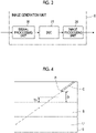
- the image analysis unit 9 detects a blood vessel B and an insertion object C included in an ultrasound image U, for example, as illustrated in Fig. 4 by analyzing the ultrasound image generated by the image generation unit 6.
- the image analysis unit 9 can detect the blood vessel B and the insertion object C in the ultrasound image U using a known algorithm.
- the image analysis unit 9 can store typical pattern data of the blood vessel B and the insertion object C in advance as a template, calculate a similarity degree for the pattern data while searching the ultrasound image U using the template, and consider that the blood vessel B and the insertion object C are present in places where the similarity degree is equal to or greater than a threshold value and is the maximum.
- Fig. 4 illustrates an example of the ultrasound image including a longitudinal cross section of the blood vessel B and a longitudinal cross section of the insertion object C.
- the insertion object C is inserted into the subject in the same plane as the longitudinal cross section of the blood vessel B.
- the longitudinal cross section of the blood vessel B refers to a cut section of the blood vessel B along a traveling direction of the blood vessel B
- the longitudinal cross section of the insertion object C refers to a cut section of the insertion object C along a direction in which the insertion object C extends.
- the image analysis unit 9 measures a distance D between a distal end P of the detected insertion object C and the blood vessel B.
- the image analysis unit 9 can measure the shortest distance in a depth direction between the distal end P of the insertion object C and the blood vessel B, as the distance D.
- the device control unit 13 controls the transmission and reception circuit 5 such that the frame rate at which the image generation unit 6 generates the ultrasound image U is adjusted, on the basis of the relative positional relationship between the blood vessel B and the insertion object C detected by the image analysis unit 9.
- the frame rate at which the ultrasound image U is generated by the image generation unit 6 is high so that the operator can grasp the motion of the insertion object C and the blood vessel B.
- the device control unit 13 can control the transmission and reception circuit 5 such that the frame rate at which the ultrasound image U is generated by the image generation unit 6 is set to a predetermined first rate in a case where the distance D between the distal end P of the insertion object C and the blood vessel B detected by the image analysis unit 9 exceeds a predetermined distance threshold value TH as illustrated in Fig. 4 , and the frame rate at which the ultrasound image U is generated by the image generation unit 6 is switched to a second rate higher than the first rate in a case where the distance D between the distal end P of the insertion object C and the blood vessel B detected by the image analysis unit 9 is equal to or less than the predetermined distance threshold value TH as illustrated in Fig. 5 .
- the transmission circuit 3 supplies the drive signal of which the amount of delay is adjusted to the plurality of transducers of the transducer array 2 such that the ultrasound beam converges on the set scan line, but the device control unit 13 decreases the number of scan lines used for generating the ultrasound image U of one frame, that is, the number of sound ray signals corresponding to the ultrasound image U of one frame by controlling the transmission circuit 3 such that the number of scan lines to which the ultrasound beam is transmitted is decreased, and thereby can switch the frame rate from the first rate to the second rate.
- the device control unit 13 increases the number of pieces of reception data phased and added for generating the sound ray signal by controlling the transmission and reception circuit 5 such that the number of scan lines for which the reception focusing processing is performed instead of decreasing the number of scan lines to which the ultrasound beam is transmitted, and thereby can increase the resolution of the ultrasound image U to be generated even after the frame rate is switched to the second rate.
- the device control unit 13 controls the transmission and reception circuit 5 such that the frame rate at which the ultrasound image U is generated by the image generation unit 6 is set to a third rate in a case where the distal end P of the insertion object C detected by the image analysis unit 9 is inserted into the blood vessel B and a displacement amount of the distal end P of the insertion object C in the blood vessel B within a predetermined time is equal to or less than a displacement amount threshold value, as illustrated in Fig. 6 .
- the displacement amount of the distal end P of the insertion object C in the blood vessel B within the predetermined time refers to a linear distance between a position of the distal end P of the insertion object C in the ultrasound image U first generated within the predetermined time and a position of the distal end P of the insertion object C in the ultrasound image U newly generated within the predetermined time, in a state where the distal end P of the insertion object C is positioned in the blood vessel B.
- the image analysis unit 9 can measure the displacement amount of the distal end P of the insertion object C in the blood vessel B within the predetermined time by analyzing a plurality of ultrasound images U consecutively generated by the image generation unit 6.
- the device control unit 13 determines whether the displacement amount of the distal end P of the insertion object C within the predetermined time, which is measured by the image analysis unit 9 in this manner, is equal to or less than the displacement amount threshold value.
- the third rate can be set to a rate equal to the first rate or lower than the first rate. That is, the third rate can be set to a rate lower than the second rate.
- the device control unit 13 can control the transmission and reception circuit 5 such that in a case where the frame rate is the third rate, the resolution of the ultrasound image U is higher than in a case where the frame rate is the second rate. In this case, the operator can accurately grasp the position of the distal end P of the insertion object C positioned in the blood vessel B of the subject.
- the third rate can also be set to a rate equal to the second rate or higher than the second rate. In this case, the operator can accurately grasp the motion of the distal end P of the insertion object C positioned in the blood vessel B.
- the device control unit 13 controls each unit of the ultrasound diagnostic apparatus 1 on the basis of a program stored in advance in the storage unit 15 or the like and the operator's input operation through the input device 14.
- the display control unit 7 performs predetermined processing on the ultrasound image U generated by the image generation unit 6 and displays the ultrasound image U on the display device 8, under the control of the device control unit 13.
- the display device 8 is for displaying the ultrasound image U, the instruction to the operator by the notification unit 12, and the like under the control of the display control unit 7, and includes a display device such as a liquid crystal display (LCD), or an organic electroluminescence (EL) display.
- a display device such as a liquid crystal display (LCD), or an organic electroluminescence (EL) display.
- the input device 14 is for the operator to perform an input operation, and can be configured to comprise a keyboard, a mouse, a trackball, a touchpad, a touch panel, and the like.
- the storage unit 15 stores a control program and the like of the ultrasound diagnostic apparatus 1, and recording media such as a flash memory, a hard disk drive (HDD), a solid state drive (SSD), a flexible disc (FD), a magneto-optical disc (MO disc), a magnetic tape (MT), a random access memory (RAM), a compact disc (CD), a digital versatile disc (DVD), a secure digital card (SD card), and a universal serial bus memory (USB memory), a server, or the like can be used.
- recording media such as a flash memory, a hard disk drive (HDD), a solid state drive (SSD), a flexible disc (FD), a magneto-optical disc (MO disc), a magnetic tape (MT), a random access memory (RAM), a compact disc (CD), a digital versatile disc (DVD), a secure digital card (SD card), and a universal serial bus memory (USB memory), a server, or the like can be used.
- the processor 22 having the image generation unit 6, the display control unit 7, the image analysis unit 9, and the device control unit 13 is configured by a central processing unit (CPU) and a control program for causing the CPU to execute various kinds of processing, but the processor 22 may be configured by using a field programmable gate array (FPGA), a digital signal processor (DSP), an application specific integrated circuit (ASIC), a graphics processing unit (GPU), or other integrated circuits (IC) or may be configured by a combination thereof.
- FPGA field programmable gate array
- DSP digital signal processor
- ASIC application specific integrated circuit
- GPU graphics processing unit
- IC integrated circuits
- the image generation unit 6, the display control unit 7, the image analysis unit 9, and the device control unit 13 of the processor 22 can also be configured by being integrated partially or entirely into one CPU or the like.
- Step S1 the ultrasound image U in which at least the blood vessel B of the subject is imaged is generated, and the generated ultrasound image U is displayed on the display device 8.
- the ultrasound probe 21 is brought into contact with the body surface of the subject by the operator, an ultrasound beam is transmitted from the plurality of transducers of the transducer array 2 according to the drive signal from the transmission circuit 3, and the reception signal is output to the reception circuit 4 from each transducer which has received the ultrasound echo from the subject.
- the reception signal received by the reception circuit 4 is amplified in the amplification unit 23, is subjected to the AD conversion in the AD conversion unit 24, and is phased and added in the beam former 25, and thereby the sound ray signal is generated.
- the sound ray signal is subjected to the envelope detection processing by the signal processing unit 26 to become the B-mode image signal in the image generation unit 6, and is output to the display control unit 7 via the DSC 27 and the image processing unit 28, and the ultrasound image U is displayed on the display device 8 under the control of the display control unit 7 as illustrated in Fig. 4 .
- Step S2 the operator inserts the insertion object C into the subject while checking the ultrasound images U consecutively generated and displayed on the display device 8.
- the image analysis unit 9 performs processing of detecting the blood vessel B and the insertion object C such as a puncture needle and a catheter by analyzing the generated ultrasound image U.
- the image analysis unit 9 can detect the blood vessel B and the insertion object C by using, for example, a known algorithm such as template matching, a machine learning method, a general image recognition method using deep learning or the like.
- Step S2 In a case where the blood vessel B and the insertion object C are not detected in Step S2, the processing returns to Step S1, the ultrasound image U is newly generated, and the processing of detecting the blood vessel B and the insertion object C is performed again in subsequent Step S2. In a case where the blood vessel B and the insertion object C are detected in Step S2, the processing proceeds to Step S3.
- Step S3 the image analysis unit 9 measures the distance D between the insertion object C and the blood vessel B of the subject detected in Step S2, as illustrated in Fig. 4 .
- the image analysis unit 9 can measure the shortest distance in the depth direction between the distal end P of the insertion object C and the blood vessel B, as the distance D.
- Step S4 the device control unit 13 determines whether the distance D between the blood vessel B and the insertion object C measured in Step S3 is equal to or less than the distance threshold value TH. In a case where the distance D between the blood vessel B and the insertion object C is greater than the distance threshold value TH as illustrated in Fig. 4 , the processing proceeds to Step S5.
- Step S5 the device control unit 13 controls the transmission and reception circuit 5 such that the frame rate at which the ultrasound image U is generated by the image generation unit 6 is set to the first rate, and the processing returns to Step S2.
- the first rate may be equal to or may be different from the frame rate used in a case where the ultrasound image U is generated in Step S1 to Step S4.
- the first rate is a rate higher than the frame rate used in a case where the ultrasound image U is generated in Step S1 to Step S4
- the operator can more accurately grasp the motion of the insertion object C inserted into the subject by checking the ultrasound image U.
- Step S5 the processing returns to Step S1, and the ultrasound image U is newly generated. Since the insertion object C and the blood vessel B of the subject are included in the ultrasound image U generated here, the blood vessel B and the insertion object C are detected in Step S2, and the processing proceeds to Step S3.
- Step S3 the blood vessel B of the subject and the insertion object C are detected and the distance D between the detected blood vessel B and insertion object C is measured on the basis of the newly generated ultrasound image U, and in Step S4, it is determined whether the measured distance D is equal to or less than the distance threshold value TH. In a case where it is determined that the distance D between the blood vessel B and the insertion object C is equal to or less than the distance threshold value TH as illustrated in Fig. 5 , the processing proceeds to Step S6.
- Step S6 the device control unit 13 controls the transmission and reception circuit 5 such that the frame rate at which the ultrasound image U is generated is switched from the first rate to the second rate greater than the first rate.
- the device control unit 13 controls the transmission and reception circuit 5 such that the number of scan lines used for generating the ultrasound image U of one frame is decreased, that is, the number of sound ray signals corresponding to the ultrasound image U of one frame is decreased, and thereby can switch the frame rate from the first rate to the second rate.
- the operator can more accurately grasp the motion of the insertion object C and the motion of the blood vessel B in a case where the insertion object C is inserted into the blood vessel B, and it is possible to improve the accuracy of inserting the insertion object C into the blood vessel B.
- the device control unit 13 increases the number of pieces of reception data phased and added for generating the sound ray signal, and thereby can increase the resolution of the ultrasound image U to be generated even after the frame rate is switched to the second rate.
- Step S7 the ultrasound image U is newly generated at the second rate.
- the image analysis unit 9 determines whether the distal end P of the insertion object C is positioned in the blood vessel B by analyzing the ultrasound image U. For example, the image analysis unit 9 can determine that the distal end P of the insertion object C is positioned in the blood vessel B by recognizing that the distal end P of the insertion object C is positioned in the blood vessel B by using, for example, a known algorithm such as template matching, a machine learning method, a general image recognition method using deep learning or the like.
- the image analysis unit 9 measures the distance D between the blood vessel B and the distal end P of the insertion object C in the same manner as in Step S3, and in a case where the measured distance D is zero, the image analysis unit 9 can determine that the distal end P of the insertion object C is positioned in the blood vessel B.
- Step S8 In a case where it is determined in Step S8 that the distal end P of the insertion object C is positioned outside the blood vessel B, the processing returns to Step S7, the ultrasound image U is newly generated, and in subsequent Step S8, it is determined again whether the distal end P of the insertion object C is positioned in the blood vessel B. In a case where it is determined in Step S8 that the distal end P of the insertion object C is positioned in the blood vessel B, the processing proceeds to Step S9.
- Step S9 the image analysis unit 9 measures the displacement amount of the distal end P of the insertion object C in the blood vessel B within the predetermined time.
- the image analysis unit 9 can measure the displacement amount of the distal end P of the insertion object C in the blood vessel B within the predetermined time by analyzing a plurality of ultrasound images U consecutively generated by the image generation unit 6.
- Step S10 the device control unit 13 determines whether the displacement amount of the distal end P of the insertion object C measured in Step S9 is equal to or less than the displacement amount threshold value. In a case where the displacement amount of the distal end P of the insertion object C measured in Step S9 is greater than the displacement amount threshold value, it is determined that the position of the distal end P of the insertion object C is not stable in the blood vessel B, the processing returns to Step S7, and the ultrasound image U is newly generated. Since the distal end P of the insertion object C is positioned in the blood vessel B in the ultrasound image U generated here, it is determined in Step S8 that the distal end P of the insertion object C is positioned in the blood vessel B, and the processing proceeds to Step S9. In Step S9, the displacement amount of the distal end P of the insertion object C is newly measured, and in Step S10, it is determined whether the newly measured displacement amount of the distal end P of the insertion object C is equal to or less than the displacement amount threshold value.
- Step S11 In a case where it is determined that the displacement amount of the distal end P of the insertion object C is equal to or less than the displacement amount threshold value, it is determined that the position of the distal end P of the insertion object C is stable in the blood vessel B, and the processing proceeds to Step S11.
- Step S11 the device control unit 13 controls the transmission and reception circuit 5 such that the frame rate at which the ultrasound image U is generated by the image generation unit 6 is set to the third rate.
- the third rate can be set to a rate equal to the first rate or lower than the first rate. That is, the third rate can be set to a rate lower than the second rate.
- the device control unit 13 can control the transmission and reception circuit 5 such that in a case where the frame rate is the third rate, the resolution of the ultrasound image U is higher than in a case where the frame rate is the second rate.
- the operator can accurately grasp the position of the insertion object C positioned in the blood vessel B of the subject, and can dispose the insertion object C at an appropriate position in the blood vessel B.
- the third rate can also be set to a rate equal to the second rate or higher than the second rate.
- the operator can accurately grasp the motion of the insertion object C positioned in the blood vessel B, and can prevent the distal end P of the insertion object C from being brought into contact with a so-called posterior vascular wall positioned in a deep portion.
- the value of the third rate can be set in advance by the operator through the input device 14, for example.
- Step S10 the processing proceeds to Step S12, and the ultrasound image U is newly generated at the third rate.
- the operator performs a procedure of moving the insertion object C or the like such that the insertion object C is disposed at an appropriate position in the blood vessel B.
- Step S13 it is determined whether to end the operation of the ultrasound diagnostic apparatus 1. For example, in a case where an instruction to end the operation of the ultrasound diagnostic apparatus 1 is input by the operator through the input device 14 or the like, it is determined that the operation of the ultrasound diagnostic apparatus 1 is to be ended, and in a case where an instruction to end the operation of the ultrasound diagnostic apparatus 1 is not input, it is determined that the operation of the ultrasound diagnostic apparatus 1 is not to be ended. In a case where it is determined that the operation of the ultrasound diagnostic apparatus 1 is not to be ended, the processing returns to Step S12, and the ultrasound image U is newly generated. In a case where it is determined that the operation of the ultrasound diagnostic apparatus 1 is to be ended, the operation of the ultrasound diagnostic apparatus 1 is ended.
- the ultrasound diagnostic apparatus 1 since the insertion object C inserted into the subject and the blood vessel B of the subject are detected by analyzing the ultrasound image U and the transmission and reception circuit 5 is automatically controlled to adjust the frame rate at which the ultrasound image U is generated by the image generation unit 6, on the basis of the relative positional relationship between the detected insertion object C and blood vessel B, the operator can automatically adjust the frame rate to an appropriate rate according to the relative positional relationship between the insertion object C and the blood vessel B while performing a procedure of inserting the insertion object C into the blood vessel B.
- the image analysis unit 9 measures the distance D between the distal end P of the insertion object C and the blood vessel B by analyzing the ultrasound image U including the longitudinal cross sections of the blood vessel B and the insertion object C, but the image analysis unit 9 can measure the distance D between the distal end P of the insertion object C and the blood vessel B by analyzing the ultrasound image U including the cross sections of the blood vessel B and the insertion object C.
- the cross section of the insertion object such as a puncture needle and a catheter is depicted to have a point shape with high brightness, and it is known that since the distal end of the insertion object has a sharp shape, a so-called acoustic shadow is less likely to occur on a deeper side than the distal end of the insertion object.
- a so-called shaft portion closer to the proximal end side than the distal end of the insertion object is thicker than the distal end, an acoustic shadow is likely to occur on a deeper side than the shaft portion of the insertion object.
- the image analysis unit 9 can measure the distance D between the distal end P of the insertion object C and the blood vessel B.
- the cross section of the blood vessel B refers to a cut section of the blood vessel B by a plane orthogonal to the traveling direction of the blood vessel B
- the cross section of the insertion object C refers to a cut section of the insertion object C by a plane orthogonal to the direction in which the insertion object C extends.
- a so-called echogenic needle in which a groove is formed on the outer peripheral portion of the puncture needle so that ultrasonic waves are easily reflected can be used.
- a puncture needle for example, since the ultrasonic waves are easily reflected in the groove formed on the outer peripheral portion of the puncture needle, a location where the puncture needle is present in the ultrasound image U becomes high brightness, and detecting the puncture needle becomes easy.
- a normal puncture needle in which no groove is formed on the outer peripheral portion can also be used as the insertion object C to be inserted into the subject.
- the image analysis unit 9 measures the diameter of the detected blood vessel B by analyzing the ultrasound image U, and the device control unit 13 can control the transmission and reception circuit 5 such that the second rate becomes a higher rate as the diameter of the blood vessel B measured by the image analysis unit 9 is decreased.
- the image analysis unit 9 can measure, for example, the radius, the length of the outer circumference, or the area of the blood vessel B instead of measuring the diameter of the blood vessel B. In this case, the image analysis unit 9 can control the transmission and reception circuit 5 such that the second rate becomes a higher rate as the measured radius, length of the outer circumference, or area of the blood vessel B is decreased.
- the device control unit 13 can control the transmission and reception circuit 5 such that the second rate becomes a high rate.
- the image analysis unit 9 detects the blood vessel B of the subject by distinguishing the vein and the artery, and in a case where the vein into which the insertion object C is to be inserted is detected as the blood vessel B and the artery is detected together with the vein, the image analysis unit 9 can measure the linear distance between the detected vein and artery. Further, the device control unit 13 can control the transmission and reception circuit 5 such that the second rate becomes a higher rate as the distance between the vein and the artery measured by the image analysis unit 9 is shorter.
- the operator can easily grasp the motion of the insertion object C by checking the ultrasound image U, and therefore, it is possible to prevent the insertion object C from being erroneously inserted into the artery.
- the device control unit 13 can display a message indicating a warning to the operator, such as "do not pierce the artery with the insertion object", on the display device 8.
- the ultrasound diagnostic apparatus 1 comprises a speaker, and the device control unit 13 can control the speaker to emit a warning sound or voice warning so that the insertion obj ect C is not inserted into the artery.
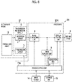
- Fig. 8 illustrates a configuration of an ultrasound diagnostic apparatus 1A according to a modification example of the first embodiment of the present invention.
- the ultrasound diagnostic apparatus 1A is obtained by adding a highlighting unit 31 to the ultrasound diagnostic apparatus 1 illustrated in Fig. 1 , comprising a device control unit 13A instead of the device control unit 13, and comprising a processor 22Ainstead of the processor 22.
- the highlighting unit 31 is connected to the image analysis unit 9, and the display control unit 7 and the device control unit 13A is connected to the highlighting unit 31.
- the highlighting unit 31 highlights the blood vessel B and the insertion object C detected by the image analysis unit 9, on the display device 8.
- the highlighting unit 31 can display the detected blood vessel B and insertion object C with a different color from that of a portion other than the blood vessel B and the insertion object C in the ultrasound image U, on the display device 8.
- the highlighting unit 31 can display texts on the display device 8 by disposing the text indicating a blood vessel near the detected blood vessel B, and disposing the text indicating an insertion object near the insertion object C.
- the operator can easily check the detected blood vessel B and insertion object C, and it is possible to improve the accuracy of inserting the insertion object C into the blood vessel B.
- the transmission and reception circuit 5 is included in the ultrasound probe 21, but may be provided outside the ultrasound probe 21. In such a case, similarly to the case where the transmission and reception circuit 5 is included in the ultrasound probe 21, the transmission and reception circuit 5 can cause the transducer array 2 to transmit the ultrasound beam toward the subject, and process the reception signal output from the transducer array 2 that has received the ultrasound echo from the subject.
- the beam former 25 that performs so-called reception focusing processing is included in the reception circuit 4, but can be included in the image generation unit 6, for example. Also in this case, similarly to the case where the beam former 25 is included in the reception circuit 4, the ultrasound image U is generated by the image generation unit 6.
- the transmission circuit 3 supplies the drive signal of which the amount of delay is adjusted to the plurality of transducers of the transducer array 2 so that the ultrasound beam converges on each of a plurality of focuses set in the depth direction, but the device control unit 13 controls the transmission circuit 3 to decrease the number of set focuses, and can increase the frame rate at which the ultrasound image U is generated by the image generation unit 6 by reducing the time required for transmitting the ultrasonic waves.
- the device control unit 13 can control the transmission and reception circuit 5 such that a depth range of the ultrasound image U, that is, the depth of field is shallow to shorten the transmission interval of the ultrasonic waves, and can increase the frame rate at which the ultrasound image U is generated by the image generation unit 6.
- the device control unit 13 controls the transmission and reception circuit 5 such that the visual field width is narrowed while the interval of the scan line is maintained, to decrease the number of times of transmitting and receiving the ultrasonic waves and decrease the number of scan lines used for generating the ultrasound image U, and thereby can increase the frame rate.
- TTI tissue harmonic imaging
- a pulse inversion method in which a first ultrasonic pulse and a second ultrasonic pulse of which phases are inverted from each other on the same scan line are sequentially transmitted into the subject, and the harmonic component is extracted by removing the fundamental wave component, which is a linear component, from the reception signal by adding the reception signal corresponding to the first ultrasonic pulse and the reception signal corresponding to the second ultrasonic pulse to each other.
- the device control unit 13 controls the transmission and reception circuit 5 and the image generation unit 6 such that the ultrasound image U is generated using the fundamental wave component of the reception signal by a normal method that does not use the pulse inversion method, and thereby can increase the frame rate at which the ultrasound image U is generated by the image generation unit 6.
- the device control unit 13 controls the transmission and reception circuit 5 and the image generation unit 6 such that the ultrasound image U is generated using, for example, the filter method, and thereby can increase the frame rate at which the ultrasound image U is generated by the image generation unit 6.
- the ultrasound diagnostic apparatus 1 of the first embodiment has the configuration in which the display device 8, the input device 14, and the ultrasound probe 21 are directly connected to the processor 22, but, for example, the display device 8, the input device 14, the ultrasound probe 21, and the processor 22 can be indirectly connected to each other via the network.
- the display device 8, the input device 14, and the ultrasound probe 21 are connected to an ultrasound diagnostic apparatus main body 41 via a network NW
- the ultrasound diagnostic apparatus main body 41 is obtained by excluding the display device 8, the input device 14, and the ultrasound probe 21 in the ultrasound diagnostic apparatus 1 of the first embodiment illustrated in Fig. 1 , and is constituted by the transmission and reception circuit 5, the storage unit 15, and the processor 22.
- the ultrasound diagnostic apparatus 1B has such a configuration, similarly to the ultrasound diagnostic apparatus 1 of the first embodiment, since the insertion object C inserted into the subject and the blood vessel B of the subject are detected by analyzing the ultrasound image U and the transmission and reception circuit 5 is automatically controlled to adjust the frame rate at which the ultrasound image U is generated by the image generation unit 6, on the basis of the relative positional relationship between the detected insertion object C and blood vessel B, the operator can adjust the frame rate to an appropriate rate according to the relative positional relationship between the insertion object C and the blood vessel B while performing a procedure of inserting the insertion object C into the blood vessel B.
- the ultrasound diagnostic apparatus main body 41 can be used as a so-called remote server.
- the operator can perform a diagnosis of the subject by preparing the display device 8, the input device 14, and the ultrasound probe 21 at the operator's hand, it is possible to improve the convenience in a case of the ultrasound diagnosis.
- a portable thin computer for example, a so-called tablet
- the display device 8 and the input device 14 it is possible for the operator to more easily perform the ultrasound diagnosis of the subject, and it is possible to further improve the convenience in a case of the ultrasound diagnosis.
- the display device 8, the input device 14, and the ultrasound probe 21 are connected to the ultrasound diagnostic apparatus main body 41 via the network NW, but in this case, the display device 8, the input device 14, and the ultrasound probe 21 may be connected to the network NW in a wired manner or in a wireless manner.
Landscapes
- Health & Medical Sciences (AREA)
- Life Sciences & Earth Sciences (AREA)
- Engineering & Computer Science (AREA)
- Medical Informatics (AREA)
- Surgery (AREA)
- Pathology (AREA)
- Radiology & Medical Imaging (AREA)
- Biophysics (AREA)
- Biomedical Technology (AREA)
- Heart & Thoracic Surgery (AREA)
- Physics & Mathematics (AREA)
- Molecular Biology (AREA)
- Nuclear Medicine, Radiotherapy & Molecular Imaging (AREA)
- Animal Behavior & Ethology (AREA)
- General Health & Medical Sciences (AREA)
- Public Health (AREA)
- Veterinary Medicine (AREA)
- Vascular Medicine (AREA)
- Computer Vision & Pattern Recognition (AREA)
- Gynecology & Obstetrics (AREA)
- Ultra Sonic Daignosis Equipment (AREA)
Abstract
Description
- The present invention relates to an ultrasound diagnostic apparatus, and a control method of the ultrasound diagnostic apparatus which display an insertion object to be inserted into a blood vessel of a subject, on an ultrasound image.
- In the related art, an ultrasound diagnostic apparatus has been known as an apparatus for obtaining an image of the inside of a subject. The ultrasound diagnostic apparatus generally comprises an ultrasound probe comprising a transducer array in which a plurality of ultrasonic transducers are arranged. In a state where the ultrasound probe is in contact with the body surface of the subject, an ultrasound beam is transmitted toward the inside of the subject from the transducer array and an ultrasound echo from the subject is received by the transducer array so that an electric signal corresponding to the ultrasound echo is acquired. Further, the ultrasound diagnostic apparatus electrically processes the obtained electric signal to generate an ultrasound image of the corresponding site of the subject.
- A procedure of inserting an insertion object such as a so-called puncture needle and a catheter into the blood vessel of the subject while observing the inside of the subject using such an ultrasound diagnostic apparatus is known. In a case where the insertion object is inserted into the blood vessel, it is desirable that the frame rate at which the ultrasound image is generated is high so that an operator can grasp the motion of the insertion object and the blood vessel. For example, as disclosed in
JP2010-88486A - However, in the ultrasound diagnostic apparatus in
JP2010-88486A - It is preferable that the frame rate is changed according to a relative positional relationship between the insertion object and the blood vessel, but the operator needs to concentrate on the procedure of inserting the insertion object into the blood vessel, and therefore, it is difficult to manually change the frame rate during the ultrasound diagnosis in some cases.
- The present invention has been made in order to solve such a problem in the related art, and an object thereof is to provide an ultrasound diagnostic apparatus, and a control method of the ultrasound diagnostic apparatus which can automatically adjust the frame rate to an appropriate rate according to a relative positional relationship between an insertion object and a blood vessel.
- In order to achieve the object, an ultrasound diagnostic apparatus according to an aspect of the present invention is an ultrasound diagnostic apparatus that displays an insertion object to be inserted into a blood vessel of a subject on an ultrasound image, and the ultrasound diagnostic apparatus comprises a transducer array; a transmission and reception circuit that causes the transducer array to transmit an ultrasound beam toward the subject, and processes a reception signal output from the transducer array that has received an ultrasound echo from the subject to generate a sound ray signal; an image generation unit that generates the ultrasound image on the basis of the sound ray signal generated by the transmission and reception circuit; an image analysis unit that detects the blood vessel and the insertion object by analyzing the ultrasound image generated by the image generation unit; and a device control unit that controls the transmission and reception circuit such that a frame rate at which the ultrasound image is generated by the image generation unit is adjusted, on the basis of a relative positional relationship between the blood vessel and the insertion object detected by the image analysis unit.
- It is preferable that the device control unit controls the transmission and reception circuit such that the frame rate at which the ultrasound image is generated by the image generation unit is set to a predetermined first rate in a case where a distance between a distal end of the insertion object and the blood vessel detected by the image analysis unit exceeds a predetermined distance threshold value, and the frame rate is switched to a second rate higher than the first rate in a case where the distance between the distal end of the insertion object and the blood vessel detected by the image analysis unit is equal to or less than the predetermined distance threshold value.
- Further, it is preferable that the device control unit controls the transmission and reception circuit such that the frame rate is set to a third rate in a case where the distal end of the insertion object detected by the image analysis unit is inserted into the blood vessel and a displacement amount of the distal end of the insertion object in the blood vessel within a predetermined time is equal to or less than a displacement amount threshold value.
- Here, the third rate may be a rate equal to the first rate or lower than the first rate.
- In this case, the device control unit controls the transmission and reception circuit such that in a case where the frame rate is the third rate, a resolution of the ultrasound image is higher than in a case where the frame rate is the second rate.
- The third rate may be a rate equal to the second rate or higher than the second rate.
- The image analysis unit may measure any one of a diameter, a radius, a length of an outer circumference, or an area of the detected blood vessel, and the device control unit may control the transmission and reception circuit such that the second rate becomes a higher rate as the diameter, the radius, the length of the outer circumference, or the area of the blood vessel measured by the image analysis unit is decreased.
- In a case where, in the ultrasound image generated by the image generation unit, a vein into which the insertion object is to be inserted is detected as the blood vessel and an artery is detected together with the vein by the image analysis unit, the image analysis unit may measure a distance between the vein and the artery, and the device control unit may control the transmission and reception circuit such that the second rate becomes a higher rate as the distance between the vein and the artery measured by the image analysis unit is shorter.
- The ultrasound diagnostic apparatus may further comprise a display device that displays the ultrasound image generated by the image generation unit; and a highlighting unit that highlights the blood vessel and the insertion object detected by the image analysis unit, on the display device.
- A control method of an ultrasound diagnostic apparatus according to another aspect of the present invention is a control method of an ultrasound diagnostic apparatus that displays an insertion object to be inserted into a blood vessel of a subject on an ultrasound image, and the control method comprises causing a transducer array to transmit an ultrasound beam toward the subject, and processing a reception signal output from the transducer array that has received an ultrasound echo from the subj ect to generate a sound ray signal; generating the ultrasound image on the basis of the generated sound ray signal; detecting the blood vessel and the insertion object by analyzing the generated ultrasound image; and adjusting a frame rate at which the ultrasound image is generated, on the basis of a relative positional relationship between the detected blood vessel and the detected insertion object.
- According to the present invention, since the ultrasound diagnostic apparatus comprises the transmission and reception circuit that causes the transducer array to transmit the ultrasound beam toward the subject, and processes the reception signal output from the transducer array that has received the ultrasound echo from the subject to generate the sound ray signal; the image generation unit that generates the ultrasound image on the basis of the sound ray signal generated by the transmission and reception circuit; the image analysis unit that detects the blood vessel and the insertion object by analyzing the ultrasound image generated by the image generation unit; and the device control unit that controls the transmission and reception circuit such that the frame rate at which the ultrasound image is generated by the image generation unit is adjusted, on the basis of the relative positional relationship between the blood vessel and the insertion object detected by the image analysis unit, it is possible to automatically adjust the frame rate to an appropriate rate according to the relative positional relationship between the insertion object and the blood vessel.
-
-
Fig. 1 is a block diagram illustrating a configuration of an ultrasound diagnostic apparatus according to a first embodiment of the present invention. -
Fig. 2 is a block diagram illustrating an internal configuration of a reception circuit in the first embodiment of the present invention. -
Fig. 3 is a block diagram illustrating an internal configuration of an image generation unit in the first embodiment of the present invention. -
Fig. 4 is a schematic diagram of an ultrasound image indicating a state in which a distance between an insertion object and a blood vessel is greater than a distance threshold value. -
Fig. 5 is a schematic diagram of an ultrasound image indicating a state in which the distance between the insertion object and the blood vessel is equal to or less than the distance threshold value. -
Fig. 6 is a schematic diagram of an ultrasound image indicating a state in which a distal end of the insertion object is inserted into the blood vessel. -
Fig. 7 is a flowchart illustrating an operation of the ultrasound diagnostic apparatus according to the first embodiment of the present invention. -
Fig. 8 is a block diagram of an ultrasound diagnostic apparatus according to a modification example of the first embodiment of the present invention. -
Fig. 9 is a block diagram illustrating an ultrasound diagnostic apparatus according to a second embodiment of the present invention. - Hereinafter, embodiments of the invention will be described with reference to the accompanying drawings.
- The description of configuration requirements described below is given on the basis of the representative embodiment of the present invention, but the present invention is not limited to such an embodiment.
- In the present specification, a numerical range represented using "to" means a range including the numerical values before and after "to" as a lower limit value and an upper limit value.
- In addition, in the present specification, the terms "perpendicular" and "parallel" include a range of errors allowed in the technical field to which the present invention belongs. For example, the terms "perpendicular" and "parallel" mean a range less than ±10 degrees with respect to the strict perpendicular or parallel, and the error with respect to the strict perpendicular or parallel is preferably 5 degrees or less, and more preferably 3 degrees or less.
- In the present specification, the terms "same" and "identical" include an error range generally allowed in the technical field. Further, in the present specification, in a case of referring to "all", "any", or "whole surface", the term includes an error range generally allowed in the technical field in addition to a case of 100%, and includes, for example, a case of 99% or more, a case of 95% or more, or a case of 90% or more.
-
Fig. 1 illustrates a configuration of an ultrasound diagnostic apparatus 1 according to a first embodiment of the present invention. The ultrasound diagnostic apparatus 1 comprises atransducer array 2, and each of atransmission circuit 3 and areception circuit 4 is connected to thetransducer array 2. Here, thetransmission circuit 3 and thereception circuit 4 constitute a transmission andreception circuit 5, and animage generation unit 6, adisplay control unit 7, and adisplay device 8 are sequentially connected to thereception circuit 4. Animage analysis unit 9 is connected to theimage generation unit 6. - In addition, a
device control unit 13 is connected to the transmission andreception circuit 5, theimage generation unit 6, thedisplay control unit 7, and theimage analysis unit 9, and aninput device 14 and astorage unit 15 are connected to thedevice control unit 13. Thedevice control unit 13 and thestorage unit 15 are connected so as to exchange information bidirectionally. - The
transducer array 2 and the transmission andreception circuit 5 are included in anultrasound probe 21. Further, theimage generation unit 6, thedisplay control unit 7, theimage analysis unit 9, and thedevice control unit 13 constitute aprocessor 22 for the ultrasound diagnostic apparatus 1. - The
transducer array 2 of theultrasound probe 21 illustrated inFig. 1 has a plurality of transducers arranged in a one-dimensional or two-dimensional manner. According to a drive signal supplied from thetransmission circuit 3, each of the transducers transmits an ultrasonic wave and receives an ultrasound echo from a subject to output a signal based on the ultrasound echo. For example, each transducer is configured by forming electrodes at both ends of a piezoelectric body consisting of piezoelectric ceramic represented by lead zirconate titanate (PZT), a polymer piezoelectric element represented by poly vinylidene di fluoride (PVDF), piezoelectric single crystal represented by lead magnesium niobate-lead titanate (PMN-PT), or the like. - The
transmission circuit 3 includes, for example, a plurality of pulse generators, and thetransmission circuit 3 adjusts the amount of delay of each drive signal so that ultrasonic waves transmitted from the plurality of transducers of thetransducer array 2 form an ultrasound beam on the basis of a transmission delay pattern selected according to the control signal from thedevice control unit 13, and supplies the obtained signals to the plurality of transducers. Thus, in a case where a pulsed or continuous-wave voltage is applied to the electrodes of the transducers of thetransducer array 2, the piezoelectric body expands and contracts to generate pulsed or continuous-wave ultrasonic waves from each transducer. From the combined wave of these ultrasonic waves, an ultrasound beam is formed. - The transmitted ultrasound beam is reflected by a target, for example, a site of the subject, and propagates toward the
transducer array 2 of theultrasound probe 21. The ultrasound echo propagating toward thetransducer array 2 in this manner is received by each transducer constituting thetransducer array 2. In this case, each transducer constituting thetransducer array 2 expands and contracts by receiving the propagating ultrasound echo to generate electric signals, and outputs the electric signals to thereception circuit 4. - The
reception circuit 4 processes the signal output from thetransducer array 2 according to the control signal from thedevice control unit 13, and generates a sound ray signal. As illustrated inFig. 2 , thereception circuit 4 has a configuration in which anamplification unit 23, an analog digital (AD)conversion unit 24, and a beam former 25 are connected in series. - The
amplification unit 23 amplifies the signal input from each transducer constituting thetransducer array 2, and transmits the amplified signal to theAD conversion unit 24. TheAD conversion unit 24 converts the signal transmitted from theamplification unit 23 into digital reception data, and transmits the reception data to the beam former 25. The beam former 25 performs so-called reception focusing processing in which addition is performed by giving delays to respective pieces of the reception data converted by theAD conversion unit 24 according to a sound speed distribution or a sound speed set on the basis of a reception delay pattern selected according to the control signal from thedevice control unit 13. Through the reception focusing processing, a sound ray signal in which each piece of the reception data converted by theAD conversion unit 24 is phased and added and the focus of the ultrasound echo is narrowed is acquired. - As illustrated in
Fig. 3 , theimage generation unit 6 has a configuration in which asignal processing unit 26, a digital scan converter (DSC) 27, and animage processing unit 28 are sequentially connected in series. - The
signal processing unit 26 generates a B-mode image signal, which is tomographic image information regarding tissues inside the subject, by performing, on the sound ray signal generated by thereception circuit 4, correction of the attenuation due to the distance according to the depth of the reflection position of the ultrasonic wave and then performing envelope detection processing. - The
DSC 27 converts (raster conversion) the B-mode image signal generated by thesignal processing unit 26 into an image signal according to a normal television signal scanning method. - The
image processing unit 28 performs various kinds of necessary image processing such as gradation processing on the B-mode image signal input from theDSC 27, and then outputs the B-mode image signal to thedisplay control unit 7 and theimage analysis unit 9. In the following, the B-mode image signal subjected to the image processing by theimage processing unit 28 is simply referred to as an ultrasound image. - In general, a procedure of inserting an insertion object such as a so-called puncture needle and a catheter into the blood vessel of the subject while observing the inside of the subject using the ultrasound diagnostic apparatus is known. The ultrasound diagnostic apparatus 1 according to the first embodiment of the present invention can be used by the operator in a case where such a procedure is performed.
- The
image analysis unit 9 detects a blood vessel B and an insertion object C included in an ultrasound image U, for example, as illustrated inFig. 4 by analyzing the ultrasound image generated by theimage generation unit 6. Here, theimage analysis unit 9 can detect the blood vessel B and the insertion object C in the ultrasound image U using a known algorithm. For example, theimage analysis unit 9 can store typical pattern data of the blood vessel B and the insertion object C in advance as a template, calculate a similarity degree for the pattern data while searching the ultrasound image U using the template, and consider that the blood vessel B and the insertion object C are present in places where the similarity degree is equal to or greater than a threshold value and is the maximum. - Further, for the calculation of the similarity degree, in addition to simple template matching, for example, a machine learning method described in Csurka et al.: Visual Categorization with Bags of Keypoints, Proc. of ECCV Workshop on Statistical Learning in Computer Vision, pp. 59-74 (2004) or a general image recognition method using deep learning described in Krizhevsk et al.: ImageNet Classification with Deep Convolutional Neural Networks, Advances in Neural ) can be used.
- Here,
Fig. 4 illustrates an example of the ultrasound image including a longitudinal cross section of the blood vessel B and a longitudinal cross section of the insertion object C. The insertion object C is inserted into the subject in the same plane as the longitudinal cross section of the blood vessel B. The longitudinal cross section of the blood vessel B refers to a cut section of the blood vessel B along a traveling direction of the blood vessel B, and the longitudinal cross section of the insertion object C refers to a cut section of the insertion object C along a direction in which the insertion object C extends. - As illustrated in
Fig. 4 , theimage analysis unit 9 measures a distance D between a distal end P of the detected insertion object C and the blood vessel B. For example, theimage analysis unit 9 can measure the shortest distance in a depth direction between the distal end P of the insertion object C and the blood vessel B, as the distance D. - The
device control unit 13 controls the transmission andreception circuit 5 such that the frame rate at which theimage generation unit 6 generates the ultrasound image U is adjusted, on the basis of the relative positional relationship between the blood vessel B and the insertion object C detected by theimage analysis unit 9. Here, in a case where the insertion object C is inserted into the blood vessel B of the subject, it is desirable that the frame rate at which the ultrasound image U is generated by theimage generation unit 6 is high so that the operator can grasp the motion of the insertion object C and the blood vessel B. For example, thedevice control unit 13 can control the transmission andreception circuit 5 such that the frame rate at which the ultrasound image U is generated by theimage generation unit 6 is set to a predetermined first rate in a case where the distance D between the distal end P of the insertion object C and the blood vessel B detected by theimage analysis unit 9 exceeds a predetermined distance threshold value TH as illustrated inFig. 4 , and the frame rate at which the ultrasound image U is generated by theimage generation unit 6 is switched to a second rate higher than the first rate in a case where the distance D between the distal end P of the insertion object C and the blood vessel B detected by theimage analysis unit 9 is equal to or less than the predetermined distance threshold value TH as illustrated inFig. 5 . - For example, the
transmission circuit 3 supplies the drive signal of which the amount of delay is adjusted to the plurality of transducers of thetransducer array 2 such that the ultrasound beam converges on the set scan line, but thedevice control unit 13 decreases the number of scan lines used for generating the ultrasound image U of one frame, that is, the number of sound ray signals corresponding to the ultrasound image U of one frame by controlling thetransmission circuit 3 such that the number of scan lines to which the ultrasound beam is transmitted is decreased, and thereby can switch the frame rate from the first rate to the second rate. It is conceivable that, in a case where the number of sound ray signals corresponding to the ultrasound image U of one frame is decreased, the resolution of the generated ultrasound image U is decreased while the frame rate is increased, but, for example, thedevice control unit 13 increases the number of pieces of reception data phased and added for generating the sound ray signal by controlling the transmission andreception circuit 5 such that the number of scan lines for which the reception focusing processing is performed instead of decreasing the number of scan lines to which the ultrasound beam is transmitted, and thereby can increase the resolution of the ultrasound image U to be generated even after the frame rate is switched to the second rate. - The
device control unit 13 controls the transmission andreception circuit 5 such that the frame rate at which the ultrasound image U is generated by theimage generation unit 6 is set to a third rate in a case where the distal end P of the insertion object C detected by theimage analysis unit 9 is inserted into the blood vessel B and a displacement amount of the distal end P of the insertion object C in the blood vessel B within a predetermined time is equal to or less than a displacement amount threshold value, as illustrated inFig. 6 . - Here, the displacement amount of the distal end P of the insertion object C in the blood vessel B within the predetermined time refers to a linear distance between a position of the distal end P of the insertion object C in the ultrasound image U first generated within the predetermined time and a position of the distal end P of the insertion object C in the ultrasound image U newly generated within the predetermined time, in a state where the distal end P of the insertion object C is positioned in the blood vessel B. For example, the
image analysis unit 9 can measure the displacement amount of the distal end P of the insertion object C in the blood vessel B within the predetermined time by analyzing a plurality of ultrasound images U consecutively generated by theimage generation unit 6. Thedevice control unit 13 determines whether the displacement amount of the distal end P of the insertion object C within the predetermined time, which is measured by theimage analysis unit 9 in this manner, is equal to or less than the displacement amount threshold value. - The third rate can be set to a rate equal to the first rate or lower than the first rate. That is, the third rate can be set to a rate lower than the second rate. In this case, the
device control unit 13 can control the transmission andreception circuit 5 such that in a case where the frame rate is the third rate, the resolution of the ultrasound image U is higher than in a case where the frame rate is the second rate. In this case, the operator can accurately grasp the position of the distal end P of the insertion object C positioned in the blood vessel B of the subject. - Further, the third rate can also be set to a rate equal to the second rate or higher than the second rate. In this case, the operator can accurately grasp the motion of the distal end P of the insertion object C positioned in the blood vessel B.
- In addition, the
device control unit 13 controls each unit of the ultrasound diagnostic apparatus 1 on the basis of a program stored in advance in thestorage unit 15 or the like and the operator's input operation through theinput device 14. - The
display control unit 7 performs predetermined processing on the ultrasound image U generated by theimage generation unit 6 and displays the ultrasound image U on thedisplay device 8, under the control of thedevice control unit 13. - The
display device 8 is for displaying the ultrasound image U, the instruction to the operator by thenotification unit 12, and the like under the control of thedisplay control unit 7, and includes a display device such as a liquid crystal display (LCD), or an organic electroluminescence (EL) display. - The
input device 14 is for the operator to perform an input operation, and can be configured to comprise a keyboard, a mouse, a trackball, a touchpad, a touch panel, and the like. - The
storage unit 15 stores a control program and the like of the ultrasound diagnostic apparatus 1, and recording media such as a flash memory, a hard disk drive (HDD), a solid state drive (SSD), a flexible disc (FD), a magneto-optical disc (MO disc), a magnetic tape (MT), a random access memory (RAM), a compact disc (CD), a digital versatile disc (DVD), a secure digital card (SD card), and a universal serial bus memory (USB memory), a server, or the like can be used. - The
processor 22 having theimage generation unit 6, thedisplay control unit 7, theimage analysis unit 9, and thedevice control unit 13 is configured by a central processing unit (CPU) and a control program for causing the CPU to execute various kinds of processing, but theprocessor 22 may be configured by using a field programmable gate array (FPGA), a digital signal processor (DSP), an application specific integrated circuit (ASIC), a graphics processing unit (GPU), or other integrated circuits (IC) or may be configured by a combination thereof. - In addition, the
image generation unit 6, thedisplay control unit 7, theimage analysis unit 9, and thedevice control unit 13 of theprocessor 22 can also be configured by being integrated partially or entirely into one CPU or the like. - In the following, the operation of the ultrasound diagnostic apparatus 1 in the first embodiment will be described in detail using the flowchart illustrated in
Fig. 7 . - First, in Step S1, the ultrasound image U in which at least the blood vessel B of the subject is imaged is generated, and the generated ultrasound image U is displayed on the
display device 8. In this case, theultrasound probe 21 is brought into contact with the body surface of the subject by the operator, an ultrasound beam is transmitted from the plurality of transducers of thetransducer array 2 according to the drive signal from thetransmission circuit 3, and the reception signal is output to thereception circuit 4 from each transducer which has received the ultrasound echo from the subject. The reception signal received by thereception circuit 4 is amplified in theamplification unit 23, is subjected to the AD conversion in theAD conversion unit 24, and is phased and added in the beam former 25, and thereby the sound ray signal is generated. The sound ray signal is subjected to the envelope detection processing by thesignal processing unit 26 to become the B-mode image signal in theimage generation unit 6, and is output to thedisplay control unit 7 via theDSC 27 and theimage processing unit 28, and the ultrasound image U is displayed on thedisplay device 8 under the control of thedisplay control unit 7 as illustrated inFig. 4 . - Next, in Step S2, the operator inserts the insertion object C into the subject while checking the ultrasound images U consecutively generated and displayed on the
display device 8. Here, theimage analysis unit 9 performs processing of detecting the blood vessel B and the insertion object C such as a puncture needle and a catheter by analyzing the generated ultrasound image U. In this case, theimage analysis unit 9 can detect the blood vessel B and the insertion object C by using, for example, a known algorithm such as template matching, a machine learning method, a general image recognition method using deep learning or the like. In a case where the blood vessel B and the insertion object C are not detected in Step S2, the processing returns to Step S1, the ultrasound image U is newly generated, and the processing of detecting the blood vessel B and the insertion object C is performed again in subsequent Step S2. In a case where the blood vessel B and the insertion object C are detected in Step S2, the processing proceeds to Step S3. - In Step S3, the
image analysis unit 9 measures the distance D between the insertion object C and the blood vessel B of the subject detected in Step S2, as illustrated inFig. 4 . For example, theimage analysis unit 9 can measure the shortest distance in the depth direction between the distal end P of the insertion object C and the blood vessel B, as the distance D. - In Step S4, the
device control unit 13 determines whether the distance D between the blood vessel B and the insertion object C measured in Step S3 is equal to or less than the distance threshold value TH. In a case where the distance D between the blood vessel B and the insertion object C is greater than the distance threshold value TH as illustrated inFig. 4 , the processing proceeds to Step S5. - In Step S5, the
device control unit 13 controls the transmission andreception circuit 5 such that the frame rate at which the ultrasound image U is generated by theimage generation unit 6 is set to the first rate, and the processing returns to Step S2. Here, the first rate may be equal to or may be different from the frame rate used in a case where the ultrasound image U is generated in Step S1 to Step S4. In a case where the first rate is a rate higher than the frame rate used in a case where the ultrasound image U is generated in Step S1 to Step S4, the operator can more accurately grasp the motion of the insertion object C inserted into the subject by checking the ultrasound image U. - In a case where Step S5 is completed, the processing returns to Step S1, and the ultrasound image U is newly generated. Since the insertion object C and the blood vessel B of the subject are included in the ultrasound image U generated here, the blood vessel B and the insertion object C are detected in Step S2, and the processing proceeds to Step S3. In Step S3, the blood vessel B of the subject and the insertion object C are detected and the distance D between the detected blood vessel B and insertion object C is measured on the basis of the newly generated ultrasound image U, and in Step S4, it is determined whether the measured distance D is equal to or less than the distance threshold value TH. In a case where it is determined that the distance D between the blood vessel B and the insertion object C is equal to or less than the distance threshold value TH as illustrated in
Fig. 5 , the processing proceeds to Step S6. - In Step S6, the
device control unit 13 controls the transmission andreception circuit 5 such that the frame rate at which the ultrasound image U is generated is switched from the first rate to the second rate greater than the first rate. In this case, for example, thedevice control unit 13 controls the transmission andreception circuit 5 such that the number of scan lines used for generating the ultrasound image U of one frame is decreased, that is, the number of sound ray signals corresponding to the ultrasound image U of one frame is decreased, and thereby can switch the frame rate from the first rate to the second rate. Since the second rate is greater than the first rate, the operator can more accurately grasp the motion of the insertion object C and the motion of the blood vessel B in a case where the insertion object C is inserted into the blood vessel B, and it is possible to improve the accuracy of inserting the insertion object C into the blood vessel B. - Here, it is conceivable that, in a case where the number of sound ray signals corresponding to the ultrasound image U of one frame is decreased, the resolution of the generated ultrasound image U is decreased while the frame rate is increased, but, for example, the
device control unit 13 increases the number of pieces of reception data phased and added for generating the sound ray signal, and thereby can increase the resolution of the ultrasound image U to be generated even after the frame rate is switched to the second rate. - In a case where the frame rate is switched to the second rate in this manner, the processing proceeds to Step S7, the ultrasound image U is newly generated at the second rate.
- In subsequent Step S8, the
image analysis unit 9 determines whether the distal end P of the insertion object C is positioned in the blood vessel B by analyzing the ultrasound image U. For example, theimage analysis unit 9 can determine that the distal end P of the insertion object C is positioned in the blood vessel B by recognizing that the distal end P of the insertion object C is positioned in the blood vessel B by using, for example, a known algorithm such as template matching, a machine learning method, a general image recognition method using deep learning or the like. Further, for example, theimage analysis unit 9 measures the distance D between the blood vessel B and the distal end P of the insertion object C in the same manner as in Step S3, and in a case where the measured distance D is zero, theimage analysis unit 9 can determine that the distal end P of the insertion object C is positioned in the blood vessel B. - In a case where it is determined in Step S8 that the distal end P of the insertion object C is positioned outside the blood vessel B, the processing returns to Step S7, the ultrasound image U is newly generated, and in subsequent Step S8, it is determined again whether the distal end P of the insertion object C is positioned in the blood vessel B. In a case where it is determined in Step S8 that the distal end P of the insertion object C is positioned in the blood vessel B, the processing proceeds to Step S9.
- In Step S9, the
image analysis unit 9 measures the displacement amount of the distal end P of the insertion object C in the blood vessel B within the predetermined time. For example, theimage analysis unit 9 can measure the displacement amount of the distal end P of the insertion object C in the blood vessel B within the predetermined time by analyzing a plurality of ultrasound images U consecutively generated by theimage generation unit 6. - In subsequent Step S10, the
device control unit 13 determines whether the displacement amount of the distal end P of the insertion object C measured in Step S9 is equal to or less than the displacement amount threshold value. In a case where the displacement amount of the distal end P of the insertion object C measured in Step S9 is greater than the displacement amount threshold value, it is determined that the position of the distal end P of the insertion object C is not stable in the blood vessel B, the processing returns to Step S7, and the ultrasound image U is newly generated. Since the distal end P of the insertion object C is positioned in the blood vessel B in the ultrasound image U generated here, it is determined in Step S8 that the distal end P of the insertion object C is positioned in the blood vessel B, and the processing proceeds to Step S9. In Step S9, the displacement amount of the distal end P of the insertion object C is newly measured, and in Step S10, it is determined whether the newly measured displacement amount of the distal end P of the insertion object C is equal to or less than the displacement amount threshold value. - In a case where it is determined that the displacement amount of the distal end P of the insertion object C is equal to or less than the displacement amount threshold value, it is determined that the position of the distal end P of the insertion object C is stable in the blood vessel B, and the processing proceeds to Step S11.
- In Step S11, the
device control unit 13 controls the transmission andreception circuit 5 such that the frame rate at which the ultrasound image U is generated by theimage generation unit 6 is set to the third rate. - Here, the third rate can be set to a rate equal to the first rate or lower than the first rate. That is, the third rate can be set to a rate lower than the second rate. In this case, the
device control unit 13 can control the transmission andreception circuit 5 such that in a case where the frame rate is the third rate, the resolution of the ultrasound image U is higher than in a case where the frame rate is the second rate. In this case, the operator can accurately grasp the position of the insertion object C positioned in the blood vessel B of the subject, and can dispose the insertion object C at an appropriate position in the blood vessel B. - Further, the third rate can also be set to a rate equal to the second rate or higher than the second rate. In this case, the operator can accurately grasp the motion of the insertion object C positioned in the blood vessel B, and can prevent the distal end P of the insertion object C from being brought into contact with a so-called posterior vascular wall positioned in a deep portion.
- The value of the third rate can be set in advance by the operator through the
input device 14, for example. - In this manner, in a case where the processing of Step S10 is completed, the processing proceeds to Step S12, and the ultrasound image U is newly generated at the third rate. In a case where the ultrasound image U is generated at the third rate, the operator performs a procedure of moving the insertion object C or the like such that the insertion object C is disposed at an appropriate position in the blood vessel B.
- In subsequent Step S13, it is determined whether to end the operation of the ultrasound diagnostic apparatus 1. For example, in a case where an instruction to end the operation of the ultrasound diagnostic apparatus 1 is input by the operator through the
input device 14 or the like, it is determined that the operation of the ultrasound diagnostic apparatus 1 is to be ended, and in a case where an instruction to end the operation of the ultrasound diagnostic apparatus 1 is not input, it is determined that the operation of the ultrasound diagnostic apparatus 1 is not to be ended. In a case where it is determined that the operation of the ultrasound diagnostic apparatus 1 is not to be ended, the processing returns to Step S12, and the ultrasound image U is newly generated. In a case where it is determined that the operation of the ultrasound diagnostic apparatus 1 is to be ended, the operation of the ultrasound diagnostic apparatus 1 is ended. - As described above, with the ultrasound diagnostic apparatus 1 according to the first embodiment of the present invention, since the insertion object C inserted into the subject and the blood vessel B of the subject are detected by analyzing the ultrasound image U and the transmission and
reception circuit 5 is automatically controlled to adjust the frame rate at which the ultrasound image U is generated by theimage generation unit 6, on the basis of the relative positional relationship between the detected insertion object C and blood vessel B, the operator can automatically adjust the frame rate to an appropriate rate according to the relative positional relationship between the insertion object C and the blood vessel B while performing a procedure of inserting the insertion object C into the blood vessel B. Thereby, it is possible to improve the accuracy with which the operator inserts the insertion object C into the blood vessel B of the subject, and even in a state where the distal end P of the insertion object C is positioned in the blood vessel B, the operator can dispose the distal end P of the insertion object C at an appropriate position. - It is described that the
image analysis unit 9 measures the distance D between the distal end P of the insertion object C and the blood vessel B by analyzing the ultrasound image U including the longitudinal cross sections of the blood vessel B and the insertion object C, but theimage analysis unit 9 can measure the distance D between the distal end P of the insertion object C and the blood vessel B by analyzing the ultrasound image U including the cross sections of the blood vessel B and the insertion object C. - In general, in the ultrasound image U, the cross section of the insertion object such as a puncture needle and a catheter is depicted to have a point shape with high brightness, and it is known that since the distal end of the insertion object has a sharp shape, a so-called acoustic shadow is less likely to occur on a deeper side than the distal end of the insertion object. On the other hand, since a so-called shaft portion closer to the proximal end side than the distal end of the insertion object is thicker than the distal end, an acoustic shadow is likely to occur on a deeper side than the shaft portion of the insertion object. Therefore, in a case where an acoustic shadow does not occur on the deep side of the insertion object C, it is determined that the insertion object C depicted in the ultrasound image U is the distal end P thereof, the
image analysis unit 9 can measure the distance D between the distal end P of the insertion object C and the blood vessel B. - Here, the cross section of the blood vessel B refers to a cut section of the blood vessel B by a plane orthogonal to the traveling direction of the blood vessel B, and the cross section of the insertion object C refers to a cut section of the insertion object C by a plane orthogonal to the direction in which the insertion object C extends.
- As the insertion object C to be inserted into the subject, a so-called echogenic needle in which a groove is formed on the outer peripheral portion of the puncture needle so that ultrasonic waves are easily reflected can be used. In a case where such a puncture needle is used, for example, since the ultrasonic waves are easily reflected in the groove formed on the outer peripheral portion of the puncture needle, a location where the puncture needle is present in the ultrasound image U becomes high brightness, and detecting the puncture needle becomes easy. However, in the ultrasound diagnostic apparatus 1 of the first embodiment of the present invention, a normal puncture needle in which no groove is formed on the outer peripheral portion can also be used as the insertion object C to be inserted into the subject.
- In a case where the insertion object C is inserted into the blood vessel B of the subject, normally, the larger the diameter of the blood vessel B, the easier it is to insert the insertion object C into the blood vessel B, and the smaller the diameter of the blood vessel B, the more difficult it is to insert the insertion object C into the blood vessel B. Therefore, the
image analysis unit 9 measures the diameter of the detected blood vessel B by analyzing the ultrasound image U, and thedevice control unit 13 can control the transmission andreception circuit 5 such that the second rate becomes a higher rate as the diameter of the blood vessel B measured by theimage analysis unit 9 is decreased. In this case, even in a case where the diameter of the detected blood vessel B is small, since the operator can easily grasp the motions of the insertion object C and the blood vessel B by checking the ultrasound image U, it is possible to improve the accuracy of inserting the insertion object C into the blood vessel B. Further, theimage analysis unit 9 can measure, for example, the radius, the length of the outer circumference, or the area of the blood vessel B instead of measuring the diameter of the blood vessel B. In this case, theimage analysis unit 9 can control the transmission andreception circuit 5 such that the second rate becomes a higher rate as the measured radius, length of the outer circumference, or area of the blood vessel B is decreased. - In a case where the insertion object C is to be inserted into the vein positioned near the artery, the
device control unit 13 can control the transmission andreception circuit 5 such that the second rate becomes a high rate. In this case, theimage analysis unit 9 detects the blood vessel B of the subject by distinguishing the vein and the artery, and in a case where the vein into which the insertion object C is to be inserted is detected as the blood vessel B and the artery is detected together with the vein, theimage analysis unit 9 can measure the linear distance between the detected vein and artery. Further, thedevice control unit 13 can control the transmission andreception circuit 5 such that the second rate becomes a higher rate as the distance between the vein and the artery measured by theimage analysis unit 9 is shorter. - In this case, even in a case where the vein into which the insertion object C is to be inserted is position near the artery, the operator can easily grasp the motion of the insertion object C by checking the ultrasound image U, and therefore, it is possible to prevent the insertion object C from being erroneously inserted into the artery.
- For example, in a case where the distance between the artery and the distal end P of the insertion object C inserted into the subject is equal to or less than a certain value, the
device control unit 13 can display a message indicating a warning to the operator, such as "do not pierce the artery with the insertion object", on thedisplay device 8. Although not illustrated, the ultrasound diagnostic apparatus 1 comprises a speaker, and thedevice control unit 13 can control the speaker to emit a warning sound or voice warning so that the insertion obj ect C is not inserted into the artery. -
Fig. 8 illustrates a configuration of an ultrasounddiagnostic apparatus 1A according to a modification example of the first embodiment of the present invention. The ultrasound diagnostic apparatus 1Ais obtained by adding a highlightingunit 31 to the ultrasound diagnostic apparatus 1 illustrated inFig. 1 , comprising adevice control unit 13A instead of thedevice control unit 13, and comprising a processor 22Ainstead of theprocessor 22. In the ultrasounddiagnostic apparatus 1A, the highlightingunit 31 is connected to theimage analysis unit 9, and thedisplay control unit 7 and thedevice control unit 13A is connected to the highlightingunit 31. - The highlighting
unit 31 highlights the blood vessel B and the insertion object C detected by theimage analysis unit 9, on thedisplay device 8. For example, although not illustrated, as the highlighting, the highlightingunit 31 can display the detected blood vessel B and insertion object C with a different color from that of a portion other than the blood vessel B and the insertion object C in the ultrasound image U, on thedisplay device 8. Further, for example, although not illustrated, as the highlighting, the highlightingunit 31 can display texts on thedisplay device 8 by disposing the text indicating a blood vessel near the detected blood vessel B, and disposing the text indicating an insertion object near the insertion object C. - In this manner, since the blood vessel B and the insertion object C detected by the
image analysis unit 9 are highlighted on thedisplay device 8, the operator can easily check the detected blood vessel B and insertion object C, and it is possible to improve the accuracy of inserting the insertion object C into the blood vessel B. - Further, the transmission and
reception circuit 5 is included in theultrasound probe 21, but may be provided outside theultrasound probe 21. In such a case, similarly to the case where the transmission andreception circuit 5 is included in theultrasound probe 21, the transmission andreception circuit 5 can cause thetransducer array 2 to transmit the ultrasound beam toward the subject, and process the reception signal output from thetransducer array 2 that has received the ultrasound echo from the subject. - Further, the beam former 25 that performs so-called reception focusing processing is included in the
reception circuit 4, but can be included in theimage generation unit 6, for example. Also in this case, similarly to the case where the beam former 25 is included in thereception circuit 4, the ultrasound image U is generated by theimage generation unit 6. - An example in which the frame rate at which the ultrasound image U is generated by the
image generation unit 6 is increased by decreasing the number of scan lines used for generating the ultrasound image U of one frame has been described, but the method of increasing the frame rate at which the ultrasound image U is generated by theimage generation unit 6 is not limited thereto. For example, thetransmission circuit 3 supplies the drive signal of which the amount of delay is adjusted to the plurality of transducers of thetransducer array 2 so that the ultrasound beam converges on each of a plurality of focuses set in the depth direction, but thedevice control unit 13 controls thetransmission circuit 3 to decrease the number of set focuses, and can increase the frame rate at which the ultrasound image U is generated by theimage generation unit 6 by reducing the time required for transmitting the ultrasonic waves. - The
device control unit 13 can control the transmission andreception circuit 5 such that a depth range of the ultrasound image U, that is, the depth of field is shallow to shorten the transmission interval of the ultrasonic waves, and can increase the frame rate at which the ultrasound image U is generated by theimage generation unit 6. - Further, the
device control unit 13 controls the transmission andreception circuit 5 such that the visual field width is narrowed while the interval of the scan line is maintained, to decrease the number of times of transmitting and receiving the ultrasonic waves and decrease the number of scan lines used for generating the ultrasound image U, and thereby can increase the frame rate. - In general, a so-called tissue harmonic imaging (THI) method is known in which the ultrasound image is generated by extracting a harmonic component, which is a non-linear component, from a signal corresponding to an ultrasound echo received by the transducer array by using the non-linearity of the signal obtained by the ultrasound echo reflected by the tissue in the subject, in order to improve the resolution of the ultrasound image to be generated. Further, as the tissue harmonic imaging method, a pulse inversion method is known in which a first ultrasonic pulse and a second ultrasonic pulse of which phases are inverted from each other on the same scan line are sequentially transmitted into the subject, and the harmonic component is extracted by removing the fundamental wave component, which is a linear component, from the reception signal by adding the reception signal corresponding to the first ultrasonic pulse and the reception signal corresponding to the second ultrasonic pulse to each other.
- Therefore, in a case where the ultrasound image U is generated using the pulse inversion method, for example, the
device control unit 13 controls the transmission andreception circuit 5 and theimage generation unit 6 such that the ultrasound image U is generated using the fundamental wave component of the reception signal by a normal method that does not use the pulse inversion method, and thereby can increase the frame rate at which the ultrasound image U is generated by theimage generation unit 6. - As a kind of tissue harmonic imaging method, in addition to the pulse inversion method, a so-called filter method is known in which the fundamental wave component is removed from the reception signal and the harmonic component is extracted by applying a frequency filter to the reception signal. Therefore, in a case where the ultrasound image U is generated using the pulse inversion method, the
device control unit 13 controls the transmission andreception circuit 5 and theimage generation unit 6 such that the ultrasound image U is generated using, for example, the filter method, and thereby can increase the frame rate at which the ultrasound image U is generated by theimage generation unit 6. - The ultrasound diagnostic apparatus 1 of the first embodiment has the configuration in which the
display device 8, theinput device 14, and theultrasound probe 21 are directly connected to theprocessor 22, but, for example, thedisplay device 8, theinput device 14, theultrasound probe 21, and theprocessor 22 can be indirectly connected to each other via the network. - As illustrated in
Fig. 9 , in an ultrasounddiagnostic apparatus 1B in a second embodiment, thedisplay device 8, theinput device 14, and theultrasound probe 21 are connected to an ultrasound diagnostic apparatusmain body 41 via a network NW The ultrasound diagnostic apparatusmain body 41 is obtained by excluding thedisplay device 8, theinput device 14, and theultrasound probe 21 in the ultrasound diagnostic apparatus 1 of the first embodiment illustrated inFig. 1 , and is constituted by the transmission andreception circuit 5, thestorage unit 15, and theprocessor 22. - Even in a case where the ultrasound
diagnostic apparatus 1B has such a configuration, similarly to the ultrasound diagnostic apparatus 1 of the first embodiment, since the insertion object C inserted into the subject and the blood vessel B of the subject are detected by analyzing the ultrasound image U and the transmission andreception circuit 5 is automatically controlled to adjust the frame rate at which the ultrasound image U is generated by theimage generation unit 6, on the basis of the relative positional relationship between the detected insertion object C and blood vessel B, the operator can adjust the frame rate to an appropriate rate according to the relative positional relationship between the insertion object C and the blood vessel B while performing a procedure of inserting the insertion object C into the blood vessel B. Thereby, it is possible to improve the accuracy with which the operator inserts the insertion object C into the blood vessel B of the subject, and even in a state where the distal end P of the insertion object C is positioned in the blood vessel B, the operator can dispose the distal end P of the insertion object C at an appropriate position. - Further, since the
display device 8, theinput device 14, and theultrasound probe 21 are connected to the ultrasound diagnostic apparatusmain body 41 via the network NW, the ultrasound diagnostic apparatusmain body 41 can be used as a so-called remote server. Thereby, for example, since the operator can perform a diagnosis of the subject by preparing thedisplay device 8, theinput device 14, and theultrasound probe 21 at the operator's hand, it is possible to improve the convenience in a case of the ultrasound diagnosis. - Further, in a case where a portable thin computer, for example, a so-called tablet, is used as the
display device 8 and theinput device 14, it is possible for the operator to more easily perform the ultrasound diagnosis of the subject, and it is possible to further improve the convenience in a case of the ultrasound diagnosis. - The
display device 8, theinput device 14, and theultrasound probe 21 are connected to the ultrasound diagnostic apparatusmain body 41 via the network NW, but in this case, thedisplay device 8, theinput device 14, and theultrasound probe 21 may be connected to the network NW in a wired manner or in a wireless manner. -
- 1, 1A, 1B: ultrasound diagnostic apparatus
- 2: transducer array
- 3: transmission circuit
- 4: reception circuit
- 5: transmission and reception circuit
- 6: image generation unit
- 7: display control unit
- 8: display device
- 9: image analysis unit
- 13: device control unit
- 14: input device
- 15: storage unit
- 21: ultrasound probe
- 22: processor
- 23: amplification unit
- 24: AD conversion unit
- 25: beam former
- 26: signal processing unit
- 27: DSC
- 28: image processing unit
- 31: highlighting unit
- 41: ultrasound diagnostic apparatus main body
- B: blood vessel
- C: insertion object
- D: distance
- NW: network
- P: distal end
- TH: distance threshold value
- U: ultrasound image
Claims (10)
- An ultrasound diagnostic apparatus that displays an insertion object to be inserted into a blood vessel of a subject on an ultrasound image, the ultrasound diagnostic apparatus comprising:a transducer array;a transmission and reception circuit that causes the transducer array to transmit an ultrasound beam toward the subject, and processes a reception signal output from the transducer array that has received an ultrasound echo from the subject to generate a sound ray signal;an image generation unit that generates the ultrasound image on the basis of the sound ray signal generated by the transmission and reception circuit;an image analysis unit that detects the blood vessel and the insertion object by analyzing the ultrasound image generated by the image generation unit; anda device control unit that controls the transmission and reception circuit such that a frame rate at which the ultrasound image is generated by the image generation unit is adjusted, on the basis of a relative positional relationship between the blood vessel and the insertion object detected by the image analysis unit.
- The ultrasound diagnostic apparatus according to claim 1,
wherein the device control unit controls the transmission and reception circuit such thatthe frame rate at which the ultrasound image is generated by the image generation unit is set to a predetermined first rate in a case where a distance between a distal end of the insertion object and the blood vessel detected by the image analysis unit exceeds a predetermined distance threshold value, andthe frame rate is switched to a second rate higher than the first rate in a case where the distance between the distal end of the insertion object and the blood vessel detected by the image analysis unit is equal to or less than the predetermined distance threshold value. - The ultrasound diagnostic apparatus according to claim 2,
wherein the device control unit controls the transmission and reception circuit such that
the frame rate is set to a third rate in a case where the distal end of the insertion object detected by the image analysis unit is inserted into the blood vessel and a displacement amount of the distal end of the insertion object in the blood vessel within a predetermined time is equal to or less than a displacement amount threshold value. - The ultrasound diagnostic apparatus according to claim 3,
wherein the third rate is a rate equal to the first rate or lower than the first rate. - The ultrasound diagnostic apparatus according to claim 4,
wherein the device control unit controls the transmission and reception circuit such that in a case where the frame rate is the third rate, a resolution of the ultrasound image is higher than in a case where the frame rate is the second rate. - The ultrasound diagnostic apparatus according to claim 3,
wherein the third rate is a rate equal to the second rate or higher than the second rate. - The ultrasound diagnostic apparatus according to any one of claims 2 to 6,wherein the image analysis unit measures any one of a diameter, a radius, a length of an outer circumference, or an area of the detected blood vessel, andthe device control unit controls the transmission and reception circuit such that the second rate becomes a higher rate as the diameter, the radius, the length of the outer circumference, or the area of the blood vessel measured by the image analysis unit is decreased.
- The ultrasound diagnostic apparatus according to any one of claims 2 to 7,wherein in a case where, in the ultrasound image generated by the image generation unit, a vein into which the insertion object is to be inserted is detected as the blood vessel and an artery is detected together with the vein by the image analysis unit, the image analysis unit measures a distance between the vein and the artery, andthe device control unit controls the transmission and reception circuit such that the second rate becomes a higher rate as the distance between the vein and the artery measured by the image analysis unit is shorter.
- The ultrasound diagnostic apparatus according to any one of claims 1 to 8, further comprising:a display device that displays the ultrasound image generated by the image generation unit; anda highlighting unit that highlights the blood vessel and the insertion object detected by the image analysis unit, on the display device.
- A control method of an ultrasound diagnostic apparatus that displays an insertion object to be inserted into a blood vessel of a subject on an ultrasound image, the control method comprising:causing a transducer array to transmit an ultrasound beam toward the subject, and processing a reception signal output from the transducer array that has received an ultrasound echo from the subject to generate a sound ray signal;generating the ultrasound image on the basis of the generated sound ray signal;detecting the blood vessel and the insertion object by analyzing the generated ultrasound image; andadjusting a frame rate at which the ultrasound image is generated, on the basis of a relative positional relationship between the detected blood vessel and the detected insertion obj ect.
Applications Claiming Priority (2)
| Application Number | Priority Date | Filing Date | Title |
|---|---|---|---|
| JP2019136914 | 2019-07-25 | ||
| PCT/JP2020/026074 WO2021014926A1 (en) | 2019-07-25 | 2020-07-02 | Ultrasonic diagnosis device and control method for ultrasonic diagnosis device |
Publications (2)
| Publication Number | Publication Date |
|---|---|
| EP4005495A1 true EP4005495A1 (en) | 2022-06-01 |
| EP4005495A4 EP4005495A4 (en) | 2022-09-14 |
Family
ID=74193789
Family Applications (1)
| Application Number | Title | Priority Date | Filing Date |
|---|---|---|---|
| EP20843651.9A Pending EP4005495A4 (en) | 2019-07-25 | 2020-07-02 | ULTRASONIC DIAGNOSTIC DEVICE AND CONTROL METHOD FOR AN ULTRASONIC DIAGNOSTIC DEVICE |
Country Status (4)
| Country | Link |
|---|---|
| US (1) | US11759173B2 (en) |
| EP (1) | EP4005495A4 (en) |
| JP (1) | JP7313446B2 (en) |
| WO (1) | WO2021014926A1 (en) |
Families Citing this family (2)
| Publication number | Priority date | Publication date | Assignee | Title |
|---|---|---|---|---|
| JP2024072894A (en) * | 2021-03-19 | 2024-05-29 | テルモ株式会社 | Puncture state identification system |
| US20230131115A1 (en) * | 2021-10-21 | 2023-04-27 | GE Precision Healthcare LLC | System and Method for Displaying Position of Echogenic Needles |
Family Cites Families (12)
| Publication number | Priority date | Publication date | Assignee | Title |
|---|---|---|---|---|
| JP2006314689A (en) * | 2005-05-16 | 2006-11-24 | Toshiba Corp | Ultrasonic diagnostic apparatus and ultrasonic diagnostic apparatus control program |
| JP2010088486A (en) | 2008-10-03 | 2010-04-22 | Toshiba Corp | Ultrasonic diagnostic apparatus |
| JP5784904B2 (en) * | 2010-12-22 | 2015-09-24 | ジーイー・メディカル・システムズ・グローバル・テクノロジー・カンパニー・エルエルシー | Ultrasonic diagnostic equipment |
| US20140187946A1 (en) * | 2012-12-31 | 2014-07-03 | General Electric Company | Active ultrasound imaging for interventional procedures |
| JP6405712B2 (en) * | 2014-05-30 | 2018-10-17 | コニカミノルタ株式会社 | Ultrasonic diagnostic equipment |
| US20160151039A1 (en) * | 2014-11-28 | 2016-06-02 | Kabushiki Kaisha Toshiba | Ultrasound diagnosis apparatus |
| JP6705134B2 (en) * | 2015-08-21 | 2020-06-03 | コニカミノルタ株式会社 | Ultrasonic image diagnostic apparatus, ultrasonic image processing method, and ultrasonic image processing program |
| EP3389759B1 (en) * | 2015-12-15 | 2020-10-28 | Corindus, Inc. | System and method for controlling x-ray frame rate of an imaging system |
| JP6171246B1 (en) * | 2016-02-09 | 2017-08-02 | 本多電子株式会社 | Ultrasonic image display device and recording medium storing program therefor |
| JP2018023610A (en) * | 2016-08-10 | 2018-02-15 | セイコーエプソン株式会社 | Ultrasonic measuring apparatus and control method |
| EP3517045A4 (en) * | 2016-09-21 | 2019-10-02 | FUJIFILM Corporation | Photoacoustic image-generating apparatus |
| WO2019205006A1 (en) * | 2018-04-25 | 2019-10-31 | 深圳迈瑞生物医疗电子股份有限公司 | Ultrasound imaging method and ultrasound imaging device |
-
2020
- 2020-07-02 JP JP2021533905A patent/JP7313446B2/en active Active
- 2020-07-02 WO PCT/JP2020/026074 patent/WO2021014926A1/en not_active Ceased
- 2020-07-02 EP EP20843651.9A patent/EP4005495A4/en active Pending
-
2021
- 2021-12-21 US US17/557,744 patent/US11759173B2/en active Active
Also Published As
| Publication number | Publication date |
|---|---|
| WO2021014926A1 (en) | 2021-01-28 |
| US20220110609A1 (en) | 2022-04-14 |
| US11759173B2 (en) | 2023-09-19 |
| JP7313446B2 (en) | 2023-07-24 |
| JPWO2021014926A1 (en) | 2021-01-28 |
| EP4005495A4 (en) | 2022-09-14 |
Similar Documents
| Publication | Publication Date | Title |
|---|---|---|
| EP4014890B1 (en) | Ultrasonic diagnostic apparatus and control method for ultrasonic diagnostic apparatus | |
| EP4005496B1 (en) | Ultrasonic diagnostic device and method for controlling ultrasonic diagnostic device | |
| US20210128102A1 (en) | Ultrasound diagnostic apparatus and control method of ultrasound diagnostic apparatus | |
| US12599359B2 (en) | Ultrasound diagnostic apparatus and method of controlling ultrasound diagnostic apparatus | |
| EP4005494B1 (en) | Ultrasonic diagnostic device and method for controlling ultrasonic diagnostic device | |
| US12594060B2 (en) | Ultrasound diagnostic apparatus, control method of ultrasound diagnostic apparatus, and processor for ultrasound diagnostic apparatus | |
| EP3865070B1 (en) | Ultrasound diagnosis device and ultrasound diagnosis device control method | |
| US20180168546A1 (en) | Ultrasound diagnostic apparatus and method for controlling ultrasound diagnostic apparatus | |
| US11759173B2 (en) | Ultrasound diagnostic apparatus and control method of ultrasound diagnostic apparatus | |
| EP4356843A1 (en) | Ultrasound diagnostic apparatus and control method of ultrasound diagnostic apparatus | |
| CN116528773A (en) | Information processing device, information processing method, and program | |
| EP4195146B1 (en) | Ultrasound diagnostic apparatus and control method of ultrasound diagnostic apparatus | |
| EP4252671B1 (en) | Ultrasound diagnostic apparatus and control program of ultrasound diagnostic apparatus | |
| CN116507288A (en) | Information processing device, information processing method, and program |
Legal Events
| Date | Code | Title | Description |
|---|---|---|---|
| STAA | Information on the status of an ep patent application or granted ep patent |
Free format text: STATUS: THE INTERNATIONAL PUBLICATION HAS BEEN MADE |
|
| PUAI | Public reference made under article 153(3) epc to a published international application that has entered the european phase |
Free format text: ORIGINAL CODE: 0009012 |
|
| STAA | Information on the status of an ep patent application or granted ep patent |
Free format text: STATUS: REQUEST FOR EXAMINATION WAS MADE |
|
| 17P | Request for examination filed |
Effective date: 20211220 |
|
| AK | Designated contracting states |
Kind code of ref document: A1 Designated state(s): AL AT BE BG CH CY CZ DE DK EE ES FI FR GB GR HR HU IE IS IT LI LT LU LV MC MK MT NL NO PL PT RO RS SE SI SK SM TR |
|
| A4 | Supplementary search report drawn up and despatched |
Effective date: 20220811 |
|
| RIC1 | Information provided on ipc code assigned before grant |
Ipc: A61B 8/00 20060101ALI20220808BHEP Ipc: A61B 8/08 20060101ALI20220808BHEP Ipc: A61B 8/14 20060101AFI20220808BHEP |
|
| DAV | Request for validation of the european patent (deleted) | ||
| DAX | Request for extension of the european patent (deleted) | ||
| STAA | Information on the status of an ep patent application or granted ep patent |
Free format text: STATUS: EXAMINATION IS IN PROGRESS |
|
| 17Q | First examination report despatched |
Effective date: 20231214 |