WO2021014926A1 - Ultrasonic diagnosis device and control method for ultrasonic diagnosis device - Google Patents
Ultrasonic diagnosis device and control method for ultrasonic diagnosis device Download PDFInfo
- Publication number
- WO2021014926A1 WO2021014926A1 PCT/JP2020/026074 JP2020026074W WO2021014926A1 WO 2021014926 A1 WO2021014926 A1 WO 2021014926A1 JP 2020026074 W JP2020026074 W JP 2020026074W WO 2021014926 A1 WO2021014926 A1 WO 2021014926A1
- Authority
- WO
- WIPO (PCT)
- Prior art keywords
- ultrasonic
- image
- blood vessel
- insert
- rate
- Prior art date
Links
Images


Classifications
-
- A—HUMAN NECESSITIES
- A61—MEDICAL OR VETERINARY SCIENCE; HYGIENE
- A61B—DIAGNOSIS; SURGERY; IDENTIFICATION
- A61B8/00—Diagnosis using ultrasonic, sonic or infrasonic waves
- A61B8/44—Constructional features of the ultrasonic, sonic or infrasonic diagnostic device
- A61B8/4483—Constructional features of the ultrasonic, sonic or infrasonic diagnostic device characterised by features of the ultrasound transducer
- A61B8/4488—Constructional features of the ultrasonic, sonic or infrasonic diagnostic device characterised by features of the ultrasound transducer the transducer being a phased array
-
- A—HUMAN NECESSITIES
- A61—MEDICAL OR VETERINARY SCIENCE; HYGIENE
- A61B—DIAGNOSIS; SURGERY; IDENTIFICATION
- A61B8/00—Diagnosis using ultrasonic, sonic or infrasonic waves
- A61B8/08—Detecting organic movements or changes, e.g. tumours, cysts, swellings
- A61B8/0833—Detecting organic movements or changes, e.g. tumours, cysts, swellings involving detecting or locating foreign bodies or organic structures
- A61B8/0841—Detecting organic movements or changes, e.g. tumours, cysts, swellings involving detecting or locating foreign bodies or organic structures for locating instruments
-
- A—HUMAN NECESSITIES
- A61—MEDICAL OR VETERINARY SCIENCE; HYGIENE
- A61B—DIAGNOSIS; SURGERY; IDENTIFICATION
- A61B8/00—Diagnosis using ultrasonic, sonic or infrasonic waves
- A61B8/08—Detecting organic movements or changes, e.g. tumours, cysts, swellings
- A61B8/0833—Detecting organic movements or changes, e.g. tumours, cysts, swellings involving detecting or locating foreign bodies or organic structures
- A61B8/085—Detecting organic movements or changes, e.g. tumours, cysts, swellings involving detecting or locating foreign bodies or organic structures for locating body or organic structures, e.g. tumours, calculi, blood vessels, nodules
-
- A—HUMAN NECESSITIES
- A61—MEDICAL OR VETERINARY SCIENCE; HYGIENE
- A61B—DIAGNOSIS; SURGERY; IDENTIFICATION
- A61B8/00—Diagnosis using ultrasonic, sonic or infrasonic waves
- A61B8/08—Detecting organic movements or changes, e.g. tumours, cysts, swellings
- A61B8/0891—Detecting organic movements or changes, e.g. tumours, cysts, swellings for diagnosis of blood vessels
-
- A—HUMAN NECESSITIES
- A61—MEDICAL OR VETERINARY SCIENCE; HYGIENE
- A61B—DIAGNOSIS; SURGERY; IDENTIFICATION
- A61B8/00—Diagnosis using ultrasonic, sonic or infrasonic waves
- A61B8/46—Ultrasonic, sonic or infrasonic diagnostic devices with special arrangements for interfacing with the operator or the patient
- A61B8/461—Displaying means of special interest
- A61B8/463—Displaying means of special interest characterised by displaying multiple images or images and diagnostic data on one display
-
- A—HUMAN NECESSITIES
- A61—MEDICAL OR VETERINARY SCIENCE; HYGIENE
- A61B—DIAGNOSIS; SURGERY; IDENTIFICATION
- A61B8/00—Diagnosis using ultrasonic, sonic or infrasonic waves
- A61B8/52—Devices using data or image processing specially adapted for diagnosis using ultrasonic, sonic or infrasonic waves
-
- A—HUMAN NECESSITIES
- A61—MEDICAL OR VETERINARY SCIENCE; HYGIENE
- A61B—DIAGNOSIS; SURGERY; IDENTIFICATION
- A61B8/00—Diagnosis using ultrasonic, sonic or infrasonic waves
- A61B8/54—Control of the diagnostic device
-
- A—HUMAN NECESSITIES
- A61—MEDICAL OR VETERINARY SCIENCE; HYGIENE
- A61B—DIAGNOSIS; SURGERY; IDENTIFICATION
- A61B8/00—Diagnosis using ultrasonic, sonic or infrasonic waves
- A61B8/56—Details of data transmission or power supply
- A61B8/565—Details of data transmission or power supply involving data transmission via a network
Definitions
- the present invention relates to an ultrasonic diagnostic apparatus that displays an insert inserted into a blood vessel of a subject on an ultrasonic image and a control method of the ultrasonic diagnostic apparatus.
- an ultrasonic diagnostic apparatus has been known as a device for obtaining an image of the inside of a subject.
- An ultrasonic diagnostic apparatus generally includes an ultrasonic probe provided with an oscillator array in which a plurality of ultrasonic oscillators are arranged. With this ultrasonic probe in contact with the body surface of the subject, an ultrasonic beam is transmitted from the transducer array toward the inside of the subject, and the ultrasonic echo from the subject is received by the transducer array to obtain an ultrasonic wave. The electrical signal corresponding to the ultrasonic echo is acquired. Further, the ultrasonic diagnostic apparatus electrically processes the obtained electric signal to generate an ultrasonic image of the site of the subject.
- the present invention has been made to solve such a conventional problem, and it is possible to automatically adjust the frame rate to an appropriate rate according to the relative positional relationship between the insert and the blood vessel. It is an object of the present invention to provide an ultrasonic diagnostic apparatus capable of providing a control method for the ultrasonic diagnostic apparatus.
- the ultrasonic diagnostic apparatus is an ultrasonic diagnostic apparatus that displays an insert to be inserted into a blood vessel of a subject on an ultrasonic image, and has an vibrator array and vibration.
- a transmission / reception circuit that generates a sound line signal by transmitting an ultrasonic beam from the child array to the subject and processing the reception signal output from the transducer array that received the ultrasonic echo from the subject.
- An image generation unit that generates an ultrasonic image based on the sound line signal generated by the circuit, an image analysis unit that detects blood vessels and inserts by analyzing the ultrasonic image generated by the image generation unit, and an image analysis unit.
- a device control unit that controls the transmission / reception circuit so that the image generation unit adjusts the frame rate for generating ultrasonic images based on the relative positional relationship between the blood vessel and the insert detected by the image analysis unit. It is characterized by having.
- the image generation unit determines the frame rate for generating an ultrasonic image. As a rate, when the distance between the tip of the insert and the blood vessel detected by the image analysis unit is less than or equal to the distance threshold value, the frame rate is switched to the second rate, which is higher than the first rate.
- the device control unit preferably controls the transmission / reception circuit.
- the frame rate is set. It is preferable that the device control unit controls the transmission / reception circuit so that the third rate is used. Here, the third rate may be equal to or lower than the first rate. At this time, the device control unit controls the transmission / reception circuit so that the resolution of the ultrasonic image is higher when the frame rate is the third rate than when the frame rate is the second rate. Can be done.
- the third rate may be equal to or higher than the second rate.
- the image analysis unit measures any of the detected diameter, radius, outer circumference length and area of the detected blood vessel
- the device control unit measures the diameter, radius and outer circumference length of the blood vessel measured by the image analysis unit.
- the transmission / reception circuit can be controlled so that the smaller the area, the higher the second rate.
- the image analysis unit performs a vein. The distance between the vein and the artery is measured, and the device control unit controls the transmission / reception circuit so that the shorter the distance between the vein and the artery measured by the image analysis unit, the higher the second rate. be able to.
- a display device that displays the ultrasonic image generated by the image generator, A highlighting unit that highlights the blood vessels and inserts detected by the image analysis unit on the display device can be further provided.
- the control method of the ultrasonic diagnostic apparatus is a control method of the ultrasonic diagnostic apparatus that displays an insertion inserted into a blood vessel of a subject on an ultrasonic image, and is directed from an oscillator array to the subject.
- the ultrasonic beam is transmitted and the received signal output from the transducer array that received the ultrasonic echo by the subject is processed to generate a sound line signal, and ultrasonic waves are generated based on the generated sound line signal.
- a frame rate that detects blood vessels and inserts by generating an image and analyzing the generated ultrasonic image, and generates an ultrasonic image based on the relative positional relationship between the detected blood vessels and inserts. It is characterized by adjusting.
- the ultrasonic beam is transmitted from the transducer array toward the subject, and the received signal output from the transducer array that has received the ultrasonic echo by the subject is processed to generate a sound line signal.
- a transmission / reception circuit so that the image generation unit adjusts the frame rate for generating ultrasonic images based on the relative positional relationship between the image analysis unit to be detected and the blood vessels and inserts detected by the image analysis unit. Since the device control unit is provided to control the frame rate, the frame rate can be automatically adjusted to an appropriate rate according to the relative positional relationship between the insert and the blood vessel.
- Embodiment 1 of this invention It is a block diagram which shows the structure of the ultrasonic diagnostic apparatus which concerns on Embodiment 1 of this invention. It is a block diagram which shows the internal structure of the receiving circuit in Embodiment 1 of this invention. It is a block diagram which shows the internal structure of the image generation part in Embodiment 1 of this invention. It is a schematic diagram of an ultrasonic image showing a state in which the distance between an insert and a blood vessel is larger than the distance threshold value. It is a schematic diagram of the ultrasonic image which shows the state which the distance between an insert and a blood vessel is less than a distance threshold value. It is a schematic diagram of the ultrasonic image which shows the state which the tip of an insert is inserted into a blood vessel.
- “same” and “same” include an error range generally accepted in the technical field. Further, in the present specification, when the term “all”, “all” or “whole surface” is used, it includes not only 100% but also an error range generally accepted in the technical field, for example, 99% or more. It shall include the case where it is 95% or more, or 90% or more.
- FIG. 1 shows the configuration of the ultrasonic diagnostic apparatus 1 according to the first embodiment of the present invention.
- the ultrasonic diagnostic apparatus 1 includes an oscillator array 2, and a transmission circuit 3 and a reception circuit 4 are connected to the oscillator array 2, respectively.
- the transmission / reception circuit 5 is configured by the transmission circuit 3 and the reception circuit 4, and the image generation unit 6, the display control unit 7, and the display device 8 are sequentially connected to the reception circuit 4.
- the image analysis unit 9 is connected to the image generation unit 6.
- the device control unit 13 is connected to the transmission / reception circuit 5, the image generation unit 6, the display control unit 7, and the image analysis unit 9, and the input device 14 and the storage unit 15 are connected to the device control unit 13. ..
- the device control unit 13 and the storage unit 15 are connected so that information can be exchanged in both directions.
- the oscillator array 2 and the transmission / reception circuit 5 are included in the ultrasonic probe 21.
- the processor 22 for the ultrasonic diagnostic apparatus 1 is configured by the image generation unit 6, the display control unit 7, the image analysis unit 9, and the device control unit 13.
- the oscillator array 2 of the ultrasonic probe 21 shown in FIG. 1 has a plurality of oscillators arranged one-dimensionally or two-dimensionally. Each of these oscillators transmits ultrasonic waves according to a drive signal supplied from the transmission circuit 3, receives an ultrasonic echo from a subject, and outputs a signal based on the ultrasonic echo.
- Each transducer includes, for example, a piezoelectric ceramic represented by PZT (Lead Zirconate Titanate), a polymer piezoelectric element represented by PVDF (PolyVinylidene DiFluoride), and PMN-PT (PMN-PT).
- Electrodes at both ends of a piezoelectric material made of a piezoelectric single crystal or the like represented by Lead Magnesium Niobate-Lead Titanate (lead magnesiumidene fluoride-lead zirconate titanate).
- the transmission circuit 3 includes, for example, a plurality of pulse generators, and is transmitted from the plurality of oscillators of the oscillator array 2 based on a transmission delay pattern selected according to a control signal from the device control unit 13.
- Each drive signal is supplied to a plurality of oscillators by adjusting the delay amount so that the ultrasonic waves form an ultrasonic beam.
- a pulsed or continuous wave voltage is applied to the electrodes of the vibrator of the vibrator array 2
- the piezoelectric body expands and contracts, and pulsed or continuous wave ultrasonic waves are generated from each vibrator.
- An ultrasonic beam is formed from the combined waves of those ultrasonic waves.
- the transmitted ultrasonic beam is reflected by, for example, a target such as a site of a subject, and propagates toward the vibrator array 2 of the ultrasonic probe 21.
- the ultrasonic echo propagating toward the vibrator array 2 in this way is received by each of the vibrators constituting the vibrator array 2.
- each oscillator constituting the oscillator array 2 expands and contracts by receiving the propagating ultrasonic echo to generate an electric signal, and outputs these electric signals to the receiving circuit 4.
- the receiving circuit 4 processes the signal output from the oscillator array 2 according to the control signal from the device control unit 13 to generate a sound line signal. As shown in FIG. 2, the receiving circuit 4 has a configuration in which an amplification unit 23, an AD (Analog Digital) conversion unit 24, and a beam former 25 are connected in series.
- AD Analog Digital
- the amplification unit 23 amplifies the signal input from each of the vibrators constituting the vibrator array 2, and transmits the amplified signal to the AD conversion unit 24.
- the AD conversion unit 24 converts the signal transmitted from the amplification unit 23 into digital reception data, and transmits these reception data to the beam former 25.
- the beam former 25 follows the sound velocity or sound velocity distribution set based on the reception delay pattern selected according to the control signal from the device control unit 13, and is used for each received data converted by the AD conversion unit 24, respectively.
- the so-called reception focus processing is performed by adding the delays of. By this reception focus processing, each received data converted by the AD conversion unit 24 is phase-adjusted and added, and a sound line signal in which the focus of the ultrasonic echo is narrowed down is acquired.
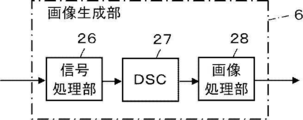
- the image generation unit 6 has a configuration in which a signal processing unit 26, a DSC (Digital Scan Converter) 27, and an image processing unit 28 are sequentially connected in series.
- the signal processing unit 26 corrects the attenuation due to the distance of the sound line signal generated by the receiving circuit 4 according to the depth of the reflection position of the ultrasonic wave, and then performs the envelope detection process to perform the subject.
- Generates a B-mode image signal which is tomographic image information about the tissue inside.
- the DSC 27 converts the B-mode image signal generated by the signal processing unit 26 into an image signal according to a normal television signal scanning method (raster conversion).
- the image processing unit 28 performs various necessary image processing such as gradation processing on the B mode image signal input from the DSC 27, and then outputs the B mode image signal to the display control unit 7 and the image analysis unit 9.
- the B-mode image signal subjected to image processing by the image processing unit 28 is simply referred to as an ultrasonic image.
- the ultrasonic diagnostic apparatus 1 can be used when such a procedure is performed by an operator.
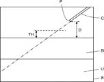
- the image analysis unit 9 analyzes the ultrasonic image generated by the image generation unit 6 to detect the blood vessel B and the insert C included in the ultrasonic image U, for example, as shown in FIG.
- the image analysis unit 9 can detect the blood vessel B and the insert C in the ultrasonic image U by using a known algorithm.
- the image analysis unit 9 stores typical pattern data of the blood vessel B and the insert C as a template in advance, calculates the similarity to the pattern data while searching the ultrasonic image U with the template, and is similar. It can be considered that the blood vessel B and the insert C are present at the place where the degree is above the threshold value and becomes the maximum.
- FIG. 4 illustrates an ultrasonic image including a vertical cross section of the blood vessel B and a vertical cross section of the insert C.
- the insert C is inserted into the subject in the same plane as the vertical cross section of the blood vessel B.
- the vertical cross section of the blood vessel B refers to the cut surface of the blood vessel B along the traveling direction of the blood vessel B
- the vertical cross section of the insert C is the vertical cross section of the insert C along the extending direction of the insert C. Refers to the cut surface.
- the image analysis unit 9 measures the distance D between the tip P of the detected insert C and the blood vessel B.
- the image analysis unit 9 can measure the shortest distance in the depth direction between the tip P of the insert C and the blood vessel B as this distance D.
- the device control unit 13 adjusts the frame rate at which the image generation unit 6 generates the ultrasonic image U based on the relative positional relationship between the blood vessel B and the insert C detected by the image analysis unit 9.
- the transmission / reception circuit 5 is controlled.
- the image generation unit 6 when the insert C is inserted into the blood vessel B of the subject, the image generation unit 6 generates an ultrasonic image U so that the operator can grasp the movements of the insert C and the blood vessel B. It is desirable that the frame rate is high. Therefore, for example, as shown in FIG. 4, the device control unit 13 exceeds the distance threshold value TH in which the distance D between the tip P of the insert C and the blood vessel B detected by the image analysis unit 9 is determined.
- the frame rate at which the ultrasonic image U is generated by the image generation unit 6 is set to the defined first rate, and as shown in FIG. 5, the tip P of the insert C detected by the image analysis unit 9 is set.
- the image generation unit 6 switches the frame rate for generating the ultrasonic image U to a second rate higher than the first rate.
- the transmission / reception circuit 5 can be controlled.
- the transmission circuit 3 supplies a drive signal whose delay amount is adjusted so that the ultrasonic beam converges on the set scanning line to the plurality of transducers of the transducer array 2, but the device control unit 13 superimposes.
- the transmission circuit 3 controls the transmission circuit 3 so as to reduce the number of scanning lines to which the sound beam is transmitted, the number of scanning lines used to generate the one-frame ultrasonic image U, that is, the one-frame ultrasonic image U
- the frame rate can be switched from the first rate to the second rate by reducing the number of sound line signals corresponding to. If the number of sound line signals corresponding to the ultrasonic image U in one frame is reduced, the frame rate may increase while the resolution of the generated ultrasonic image U may decrease.
- the unit 13 controls the transmission / reception circuit 5 so as to increase the number of scanning lines for which reception focus processing is performed instead of decreasing the number of scanning lines for which the ultrasonic beam is transmitted.
- the resolution of the generated ultrasonic image U can be increased even after the frame rate is switched to the second rate.
- the device control unit 13 inserts the tip P of the insert C detected by the image analysis unit 9 into the blood vessel B and inserts the insert C in the blood vessel B at a predetermined time.
- the transmission / reception circuit 5 is controlled so that the frame rate at which the ultrasonic image U is generated by the image generation unit 6 is set as the third rate.
- the displacement amount of the tip P of the insert C in the blood vessel B at the specified time is the first displacement within the specified time in the state where the tip P of the insert C is located in the blood vessel B. It refers to the linear distance between the position of the tip P of the insert C in the generated ultrasonic image U and the position of the tip P of the insert C in the newly generated ultrasonic image U within a predetermined time. ..
- the image analysis unit 9 analyzes a plurality of ultrasonic images U continuously generated by the image generation unit 6 to determine the displacement amount of the tip P of the insert C in the blood vessel B at a predetermined time. Can be measured.
- the device control unit 13 determines whether or not the displacement amount of the tip P of the insert C at the predetermined time measured by the image analysis unit 9 is equal to or less than the displacement threshold value.
- the third rate can be set to a rate equal to or lower than the first rate. That is, the third rate can be set to a lower rate than the second rate.
- the device control unit 13 controls the transmission / reception circuit 5 so that the resolution of the ultrasonic image U is higher when the frame rate is the third rate than when the frame rate is the second rate. Can be done. In this case, the operator can accurately grasp the position of the tip P of the insert C located in the blood vessel B of the subject.
- the third rate can be set to a rate equal to or higher than the second rate. In this case, the operator can accurately grasp the movement of the tip P of the insert C located in the blood vessel B.
- the device control unit 13 controls each part of the ultrasonic diagnostic device 1 based on a program stored in advance in the storage unit 15 or the like and an input operation by the operator via the input device 14. ..
- the display control unit 7 performs a predetermined process on the ultrasonic image U generated by the image generation unit 6 and displays the ultrasonic image U on the display device 8.
- the display device 8 displays an ultrasonic image U, instructions to the operator by the notification unit 12, and the like under the control of the display control unit 7.
- an LCD Liquid Crystal Display
- an organic EL Includes display devices such as displays (Organic Electroluminescence Display).
- the input device 14 is for the operator to perform an input operation, and can be configured to include a keyboard, a mouse, a trackball, a touch pad, a touch panel, and the like.
- the storage unit 15 stores a control program or the like of the ultrasonic diagnostic apparatus 1, and includes a flash memory, an HDD (Hard Disc Drive), an SSD (Solid State Drive), and an FD (Flexible Disc).
- Disc Magnetic-Optical disc
- MT Magnetic Tape: magnetic tape
- RAM Random Access Memory: random access memory
- CD Compact Disc
- DVD Digital Versatile Disc
- SD card Secure Digital card
- USB memory Universal Serial Bus memory
- the processor 22 having the image generation unit 6, the display control unit 7, the image analysis unit 9, and the device control unit 13 is for causing the CPU (Central Processing Unit) and the CPU to perform various processes. It consists of control programs, but is composed of FPGA (Field Programmable Gate Array), DSP (Digital Signal Processor: Digital Signal Processor), ASIC (Application Specific Integrated Circuit), GPU (Graphics Processing). It may be configured by using a Unit: graphics processing unit) or another IC (Integrated Circuit), or may be configured by combining them.
- FPGA Field Programmable Gate Array
- DSP Digital Signal Processor: Digital Signal Processor
- ASIC Application Specific Integrated Circuit
- GPU Graphics Processing
- the image generation unit 6, the display control unit 7, the image analysis unit 9, and the device control unit 13 of the processor 22 can be partially or wholly integrated into one CPU or the like.
- step S1 an ultrasonic image U in which at least the blood vessel B of the subject is imaged is generated, and the generated ultrasonic image U is displayed on the display device 8.
- the operator contacts the ultrasonic probe 21 on the body surface of the subject, and ultrasonic waves are emitted into the subject from the plurality of vibrators of the vibrator array 2 according to the drive signal from the transmission circuit 3.
- the beam is transmitted, and the received signal is output to the receiving circuit 4 from each oscillator that has received the ultrasonic echo from the subject.
- the received signal received by the receiving circuit 4 is amplified by the amplification unit 23, AD-converted by the AD conversion unit 24, and then phase-aligned and added by the beam former 25 to generate a sound line signal.
- This sound line signal becomes a B-mode image signal when the signal processing unit 26 performs envelope detection processing in the image generation unit 6, and is output to the display control unit 7 via the DSC 27 and the image processing unit 28.
- the ultrasonic image U is displayed on the display device 8 under the control of the display control unit 7.
- step S2 the operator inserts the insert C into the subject while checking the ultrasonic image U that is continuously generated and displayed on the display device 8.
- the image analysis unit 9 performs a process of detecting the blood vessel B and the insert C such as the puncture needle and the catheter by analyzing the generated ultrasonic image U.
- the image analysis unit 9 can detect the blood vessel B and the insert C by using a known algorithm such as a template matching, a machine learning method, a general image recognition method using deep learning, or the like. If the blood vessel B and the insert C are not detected in step S2, the process returns to step S1 to generate a new ultrasonic image U, and in the following step S2, the process of detecting the blood vessel B and the insert C is performed again. Will be If the blood vessel B and the insert C are detected in step S2, the process proceeds to step S3.
- step S3 the image analysis unit 9 measures the distance D between the blood vessel B of the subject and the insert C detected in step S2.
- the image analysis unit 9 can measure the shortest distance in the depth direction between the tip P of the insert C and the blood vessel B as this distance D.
- step S4 the device control unit 13 determines whether or not the distance D between the blood vessel B and the insert C measured in step S3 is equal to or less than the distance threshold value TH. As shown in FIG. 4, when the distance D between the blood vessel B and the insert C is larger than the distance threshold value TH, the process proceeds to step S5.
- step S5 the device control unit 13 controls the transmission / reception circuit 5 so that the frame rate at which the ultrasonic image U is generated by the image generation unit 6 is the first rate, and returns to step S2.
- the first rate may be equal to or different from the frame rate used when the ultrasonic image U was generated in steps S1 to S4.
- the operator confirms the ultrasonic image U. , The movement of the insert C inserted in the subject can be grasped more accurately.
- step S5 the process returns to step S1 and a new ultrasonic image U is generated. Since the ultrasonic image U generated here contains the blood vessel B and the insert C of the subject, the blood vessel B and the insert C are detected in step S2, and the process proceeds to step S3.
- step S3 the blood vessel B and the insert C of the subject are detected based on the newly generated ultrasonic image U, and the distance D between the detected blood vessel B and the insert C is measured.
- step S4 It is determined whether or not the measured distance D is equal to or less than the distance threshold value TH. As shown in FIG. 5, when it is determined that the distance D between the blood vessel B and the insert C is equal to or less than the distance threshold value TH, the process proceeds to step S6.
- step S6 the device control unit 13 controls the transmission / reception circuit 5 so as to switch the frame rate at which the ultrasonic image U is generated from the first rate to the second rate larger than the first rate.
- the device control unit 13 reduces the number of scanning lines used to generate the ultrasonic image U of one frame, that is, the sound line signal corresponding to the ultrasonic image U of one frame.
- the frame rate can be switched from the first rate to the second rate. Since the second rate is larger than the first rate, the operator can more accurately grasp the movement of the insert C and the movement of the blood vessel B when the insert C is inserted into the blood vessel B, and insert the insert. The accuracy of inserting the object C into the blood vessel B can be improved.
- the device control unit 13 generates the ultrasonic image U even after the frame rate is switched to the second rate by increasing the number of received data to be phase-aligned and added in order to generate the sound line signal.
- the resolution of can be increased.
- step S8 the image analysis unit 9 analyzes the ultrasonic image U to determine whether or not the tip P of the insert C is located in the blood vessel B.
- the image analysis unit 9 uses a known algorithm such as a template matching, a machine learning method, a general image recognition method using deep learning, etc. to determine that the tip P of the insert C is located in the blood vessel B. By recognizing, it can be determined that the tip P of the insert C is located in the blood vessel B.
- the image analysis unit 9 measures the distance D between the blood vessel B and the tip P of the insert C in the same manner as in step S3, and when the measured distance D becomes 0, the tip of the insert C It can be determined that P is located in the blood vessel B.
- step S8 If it is determined in step S8 that the tip P of the insert C is located outside the blood vessel B, the process returns to step S7, a new ultrasonic image U is generated, and in the following step S8, the insert C is generated. Whether or not the tip P of the tip P is located in the blood vessel B is determined again. If it is determined in step S8 that the tip P of the insert C is located in the blood vessel B, the process proceeds to step S9.
- step S9 the image analysis unit 9 measures the displacement amount of the tip P of the insert C in the blood vessel B at a predetermined time.
- the image analysis unit 9 analyzes a plurality of ultrasonic images U continuously generated by the image generation unit 6 to determine the displacement amount of the tip P of the insert C in the blood vessel B at a predetermined time. Can be measured.
- step S10 the device control unit 13 determines whether or not the displacement amount of the tip P of the insert C measured in step S9 is equal to or less than the displacement amount threshold value.
- the displacement amount of the tip P of the insert C measured in step S9 is larger than the displacement amount threshold value, it is determined that the position of the tip P of the insert C is not stable in the blood vessel B.
- step S7 a new ultrasonic image U is generated. In the ultrasonic image U generated here, since the tip P of the insert C is located in the blood vessel B, it is determined in step S8 that the tip P of the insert C is located in the blood vessel B. , Step S9.
- step S9 the displacement amount of the tip P of the insert C is newly measured, and in step S10, whether or not the displacement amount of the newly measured tip P of the insert C is equal to or less than the displacement threshold value. It is judged. When it is determined that the displacement amount of the tip P of the insert C is equal to or less than the displacement threshold value, it is determined that the position of the tip P of the insert C is stable in the blood vessel B, and the process proceeds to step S11. ..
- step S11 the device control unit 13 controls the transmission / reception circuit 5 so that the frame rate at which the ultrasonic image U is generated by the image generation unit 6 is set as the third rate.
- the third rate can be set to a rate equal to or lower than the first rate. That is, the third rate can be set to a lower rate than the second rate.
- the device control unit 13 controls the transmission / reception circuit 5 so that the resolution of the ultrasonic image U is higher when the frame rate is the third rate than when the frame rate is the second rate. Can be done. In this case, the operator can accurately grasp the position of the insert C located in the blood vessel B of the subject and place the insert C at an appropriate position in the blood vessel B.
- the third rate can also be set to a rate equal to or higher than the second rate.
- the operator accurately grasps the movement of the insert C located in the blood vessel B and prevents the tip P of the insert C from coming into contact with the so-called posterior wall of the blood vessel located in the deep part. Can be done.
- the value of the third rate can be preset by the operator via, for example, the input device 14.
- step S10 when the processing of step S10 is completed, the process proceeds to step S12, and a new ultrasonic image U is generated under the third rate.
- the operator performs a procedure such as moving the insert C so as to place the insert C at an appropriate position in the blood vessel B.
- step S13 it is determined whether or not the operation of the ultrasonic diagnostic apparatus 1 is terminated. For example, when the operator inputs an instruction to end the operation of the ultrasonic diagnostic device 1 via the input device 14 or the like, it is determined that the operation of the ultrasonic diagnostic device 1 is terminated, and the ultrasonic diagnostic device 1 is terminated. If the instruction to end the operation of 1 is not input, it can be determined that the operation of the ultrasonic diagnostic apparatus 1 is not ended. If it is determined that the operation of the ultrasonic diagnostic apparatus 1 is not completed, the process returns to step S12, and a new ultrasonic image U is generated. When it is determined that the operation of the ultrasonic diagnostic apparatus 1 is terminated, the operation of the ultrasonic diagnostic apparatus 1 is terminated.
- the insert C inserted into the subject and the blood vessel B of the subject are detected by analyzing the ultrasonic image U.
- the transmission / reception circuit 5 is automatically controlled so that the image generation unit 6 adjusts the frame rate for generating the ultrasonic image U based on the relative positional relationship between the detected insert C and the blood vessel B. Therefore, even though the operator is performing the procedure of inserting the insert C into the blood vessel B, the frame rate is automatically adjusted to an appropriate rate according to the relative positional relationship between the insert C and the blood vessel B. be able to. Further, this improves the accuracy with which the operator inserts the insert C into the blood vessel B of the subject, and even when the tip P of the insert C is located in the blood vessel B, the operator can use the insert C. The tip P can be placed at an appropriate position.
- the image analysis unit 9 measures the distance D between the tip P of the insert C and the blood vessel B by analyzing the ultrasonic image U including the vertical cross section of the blood vessel B and the insert C.
- the image analysis unit 9 can also measure the distance D between the tip P of the insert C and the blood vessel B by analyzing the ultrasonic image U including the cross section of the blood vessel B and the insert C.
- the cross section of the insert such as the puncture needle and the catheter is drawn so as to have a high-intensity point shape, and the tip of the insert has a sharp shape. Therefore, it is known that so-called acoustic shadows are less likely to occur on the deeper side than the tip of the insert.
- the image analysis unit 9 determines that the insert C drawn on the ultrasonic image U is the tip P of the insert C, for example, when no acoustic shadow is generated on the deep side of the insert C.
- the distance D between the tip P of C and the blood vessel B can be measured.
- the cross section of the blood vessel B refers to a cut surface of the blood vessel B by a plane orthogonal to the traveling direction of the blood vessel B, and the cross section of the insert C is orthogonal to the direction in which the insert C extends. Refers to the cut surface of the insert C due to the plane to be formed.
- a so-called echogenic needle having a groove formed on the outer peripheral portion of the puncture needle can be used so that ultrasonic waves can be easily reflected.
- a puncture needle for example, since ultrasonic waves are easily reflected in the groove formed on the outer peripheral portion of the puncture needle, the portion where the puncture needle exists in the ultrasonic image U becomes high brightness. , The puncture needle can be easily detected.
- a normal puncture needle having no groove formed on the outer peripheral portion can be used as the insert C to be inserted into the subject.
- the image analysis unit 9 measures the diameter of the detected blood vessel B by analyzing the ultrasonic image U, and the device control unit 13 increases the smaller the diameter of the blood vessel B measured by the image analysis unit 9.
- the transmission / reception circuit 5 can be controlled so that the second rate becomes a high rate.
- the image analysis unit 9 can measure, for example, the radius of the blood vessel B, the length of the outer circumference, the area, and the like. In this case, the image analysis unit 9 can control the transmission / reception circuit 5 so that the smaller the measured radius, outer circumference length, area, or the like of the measured blood vessel B, the higher the second rate. ..
- the device control unit 13 can control the transmission / reception circuit 5 so that the second rate becomes a high rate when the insert C is inserted into the vein located near the artery.
- the image analysis unit 9 detects, for example, the blood vessel B of the subject by distinguishing between the vein and the artery, detects the vein into which the insert C is inserted as the blood vessel B, and detects the artery together with the vein. In this case, the linear distance between the detected vein and artery can be measured. Further, the device control unit 13 can control the transmission / reception circuit 5 so that the shorter the distance between the vein and the artery measured by the image analysis unit 9, the higher the second rate.
- the device control unit 13 says, "Do not pierce the artery with the insert.”
- a message indicating a warning to the operator can be displayed on the display device 8.
- the ultrasonic diagnostic apparatus 1 is provided with a speaker, and the apparatus control unit 13 can control the speaker so as to emit a warning sound or a voice warning not to insert the insert C into the artery. ..
- FIG. 8 shows the configuration of the ultrasonic diagnostic apparatus 1A according to the modified example of the first embodiment of the present invention.
- the ultrasonic diagnostic apparatus 1A is provided with an apparatus control unit 13A instead of the apparatus control unit 13 and a processor 22A instead of the processor 22, and a highlighting unit 31 is added. It is a thing.
- the highlighting unit 31 is connected to the image analysis unit 9, and the display control unit 7 and the device control unit 13 are connected to the highlighting unit 31.
- the highlighting unit 31 highlights the blood vessel B and the insert C detected by the image analysis unit 9 on the display device 8. For example, the highlighting unit 31 displays the detected blood vessel B and the insert C on the display device 8 as a highlight in a color different from the parts other than the blood vessel B and the insert C in the ultrasonic image U, although not shown. Can be displayed. Further, for example, the highlighting unit 31 arranges a text indicating that it is a blood vessel in the vicinity of the detected blood vessel B, and a text indicating that it is an insert in the vicinity of the insert C, although not shown, as a highlight. These texts can also be arranged and displayed on the display device 8.
- the blood vessel B and the insert C detected by the image analysis unit 9 are highlighted on the display device 8, so that the operator can easily confirm the detected blood vessel B and the insert C.
- the accuracy of inserting the insert C into the blood vessel B can be improved.
- the transmission / reception circuit 5 is included in the ultrasonic probe 21, it may be provided outside the ultrasonic probe 21. Even in such a case, the transmission / reception circuit 5 transmits an ultrasonic beam from the vibrator array 2 toward the subject in the same manner as when the transmission / reception circuit 5 is included in the ultrasonic probe 21. It is possible to process the received signal output from the oscillator array 2 that has received the ultrasonic echo by the subject.
- the beam former 25 that performs so-called reception focus processing is included in the reception circuit 4, it can also be included in the image generation unit 6, for example. Even in this case, the ultrasonic image U is generated by the image generation unit 6 as in the case where the beam former 25 is included in the receiving circuit 4.
- the image generation unit 6 increases the frame rate for generating the ultrasonic image U by reducing the number of scanning lines used to generate the ultrasonic image U of one frame.
- the method by which the image generation unit 6 increases the frame rate for generating the ultrasonic image U is not limited to this.
- the transmission circuit 3 supplies a drive signal whose delay amount is adjusted so that the ultrasonic beam converges with respect to a plurality of focal points set in the depth direction to the plurality of vibrators of the vibrator array 2.
- the device control unit 13 controls the transmission circuit 3 so as to reduce the number of focal points set, for example, to reduce the time required for transmitting ultrasonic waves, so that the image generation unit 6 generates the ultrasonic image U.
- the frame rate can be increased.
- the device control unit 13 shortens the ultrasonic transmission interval by controlling the transmission / reception circuit 5 so as to make the depth range of the ultrasonic image U, that is, the viewing depth shallow, for example, and the image generation unit 6 Can increase the frame rate that produces the ultrasonic image U. Further, the device control unit 13 reduces the number of transmissions and receptions of ultrasonic waves and obtains the ultrasonic image U by controlling the transmission / reception circuit 5 so as to narrow the so-called visual field width while maintaining the interval between scanning lines, for example. The frame rate can be increased by reducing the number of scanning lines used for generation.
- Tissue harmonic imaging (THI) method in which a harmonic component, which is a non-linear component, is extracted from a signal corresponding to an ultrasonic echo to generate an ultrasonic image.
- TTI tissue harmonic imaging
- a first ultrasonic pulse and a second ultrasonic pulse whose phases are inverted with each other on the same scanning line are sequentially transmitted into the subject to correspond to the first ultrasonic pulse.
- a pulse inversion method is known in which a harmonic component is extracted by removing a fundamental wave component which is a linear component from a received signal by adding the received signal to be received and the received signal corresponding to the second received signal to each other.
- the device control unit 13 uses the fundamental wave component of the received signal by, for example, a normal method that does not use the pulse inversion method.
- the frame rate at which the image generation unit 6 generates the ultrasonic image U can be increased.
- the device control unit 13 uses the filter method to generate the ultrasonic image U, for example, the transmission / reception circuit 5 and the image. By controlling the generation unit 6, the frame rate at which the image generation unit 6 generates the ultrasonic image U can be increased.
- the ultrasonic diagnostic apparatus 1 of the first embodiment has a configuration in which the display device 8, the input device 14, and the ultrasonic probe 21 are directly connected to the processor 22, but for example, the display device 8 and the input device. 14.
- the ultrasonic probe 21 and the processor 22 can also be indirectly connected via a network.
- the display device 8, the input device 14, and the ultrasonic probe 21 are connected to the ultrasonic diagnostic apparatus main body 41 via the network NW. ..
- the ultrasonic diagnostic apparatus main body 41 is the ultrasonic diagnostic apparatus 1 of the first embodiment shown in FIG. 1, excluding the display device 8, the input device 14, and the ultrasonic probe 21, the transmission / reception circuit 5, and the storage unit 15. And a processor 22.
- the insert C inserted into the subject by analyzing the ultrasonic image U is the same as the ultrasonic diagnostic apparatus 1 of the first embodiment.
- the blood vessel B of the subject are detected, and the frame rate for generating the ultrasonic image U is adjusted by the image generation unit 6 based on the relative positional relationship between the detected insert C and the blood vessel B. Since the transmission / reception circuit 5 is automatically controlled, the frame rate is set according to the relative positional relationship between the insert C and the blood vessel B, even though the operator is performing the procedure of inserting the insert C into the blood vessel B. It can be adjusted to an appropriate rate. Further, this improves the accuracy with which the operator inserts the insert C into the blood vessel B of the subject, and even when the tip P of the insert C is located in the blood vessel B, the operator can use the insert C. The tip P can be placed at an appropriate position.
- the ultrasonic diagnostic device main body 41 can be used as a so-called remote server. ..
- the operator can diagnose the subject by preparing the display device 8, the input device 14, and the ultrasonic probe 21 at the operator's hand, which is convenient for ultrasonic diagnosis.
- the sex can be improved.
- a portable thin computer called a so-called tablet is used as the display device 8 and the input device 14, the operator can more easily perform ultrasonic diagnosis of the subject and ultrasonic waves. The convenience of diagnosis can be further improved.
- the display device 8, the input device 14, and the ultrasonic probe 21 are connected to the ultrasonic diagnostic device main body 41 via the network NW. At this time, the display device 8, the input device 14, and the ultrasonic probe 21 are connected.
- the network NW may be wiredly connected or wirelessly connected.
- 1,1A, 1B ultrasonic diagnostic equipment 2 oscillator array, 3 transmission circuit, 4 reception circuit, 5 transmission / reception circuit, 6 image generation unit, 7 display control unit, 8 display device, 9 image analysis unit, 13 device control unit , 14 input device, 15 storage unit, 21 ultrasonic probe, 22 processor, 23 amplification unit, 24 AD conversion unit, 25 beam former, 26 signal processing unit, 27 DSC, 28 image processing unit, 31 highlighting unit, 41 super Ultrasound diagnostic device body, B blood vessel, C insert, D distance, NW network, P tip, TH distance threshold, U ultrasonic image.
Abstract
This ultrasonic diagnosis device (1) is provided with: a transmission and reception circuit (5) which causes an ultrasonic beam to be transmitted from a vibrator array (2) towards a specimen and processes a reception signal output from the vibrator array, which has received an ultrasonic echo from the specimen, to generate a sound ray signal; an image generation unit (6) which generates an ultrasonic image on the basis of the generated sound ray signal; an image analysis unit (9) which detects a blood vessel and an insertion object by analyzing the generated ultrasonic image; and a device control unit (13) which controls the transmission and reception circuit (5) so that a frame rate for generating the ultrasonic image is adjusted on the basis of the positional relationship between the detected blood vessel and the insertion object.
Description
本発明は、被検体の血管に挿入される挿入物を超音波画像上に表示する超音波診断装置およびその超音波診断装置の制御方法に関する。
The present invention relates to an ultrasonic diagnostic apparatus that displays an insert inserted into a blood vessel of a subject on an ultrasonic image and a control method of the ultrasonic diagnostic apparatus.
従来から、被検体の内部の画像を得るものとして、超音波診断装置が知られている。超音波診断装置は、一般的に、複数の超音波振動子が配列された振動子アレイが備えられた超音波プローブを備えている。この超音波プローブを被検体の体表面に接触させた状態において、振動子アレイから被検体内に向けて超音波ビームが送信され、被検体からの超音波エコーを振動子アレイにおいて受信して超音波エコーに対応する電気信号が取得される。さらに、超音波診断装置は、得られた電気信号を電気的に処理して、被検体の当該部位に対する超音波画像を生成する。
Conventionally, an ultrasonic diagnostic apparatus has been known as a device for obtaining an image of the inside of a subject. An ultrasonic diagnostic apparatus generally includes an ultrasonic probe provided with an oscillator array in which a plurality of ultrasonic oscillators are arranged. With this ultrasonic probe in contact with the body surface of the subject, an ultrasonic beam is transmitted from the transducer array toward the inside of the subject, and the ultrasonic echo from the subject is received by the transducer array to obtain an ultrasonic wave. The electrical signal corresponding to the ultrasonic echo is acquired. Further, the ultrasonic diagnostic apparatus electrically processes the obtained electric signal to generate an ultrasonic image of the site of the subject.
このような超音波診断装置を用いて被検体内を観察しながら、いわゆる穿刺針およびカテーテル等の挿入物を被検体の血管内に挿入する手技が知られている。挿入物が血管内に挿入される場合には、操作者が挿入物および血管の動きを把握できるように、超音波画像が生成されるフレームレートが高いレートであることが望ましい。そこで、例えば特許文献1に開示されているように、超音波画像において挿入物が検出されたことをトリガとして超音波画像を生成するフレームレートを自動的に上昇させる超音波診断装置が開発されている。
There is known a technique of inserting an insert such as a so-called puncture needle and a catheter into a blood vessel of a subject while observing the inside of the subject using such an ultrasonic diagnostic apparatus. When the insert is inserted into the blood vessel, it is desirable that the frame rate at which the ultrasound image is generated is high so that the operator can grasp the movement of the insert and the blood vessel. Therefore, for example, as disclosed in Patent Document 1, an ultrasonic diagnostic apparatus has been developed that automatically increases the frame rate for generating an ultrasonic image triggered by the detection of an insert in an ultrasonic image. There is.
しかしながら、特許文献1の超音波診断装置では、挿入物が検出されたことをトリガとしてフレームレートを上昇させるため、例えば、挿入物と血管との距離が十分に離れている場合であっても、フレームレートが必要以上に高いレートとなってしまい、無駄に消費電力が大きくなるという問題がある。
仮に、挿入物と血管との相対的な位置関係に応じてフレームレートが変化すれば好ましいが、操作者は、挿入物を血管に挿入する手技に集中する必要があるため、超音波診断の途中で手動によりフレームレートを変更することは困難となる場合がある。 However, in the ultrasonic diagnostic apparatus ofPatent Document 1, since the frame rate is increased by triggering the detection of the insert, for example, even when the distance between the insert and the blood vessel is sufficiently large, There is a problem that the frame rate becomes higher than necessary and the power consumption becomes unnecessarily large.
It is preferable that the frame rate changes according to the relative positional relationship between the insert and the blood vessel, but since the operator needs to concentrate on the procedure for inserting the insert into the blood vessel, the ultrasonic diagnosis is in progress. It may be difficult to change the frame rate manually with.
仮に、挿入物と血管との相対的な位置関係に応じてフレームレートが変化すれば好ましいが、操作者は、挿入物を血管に挿入する手技に集中する必要があるため、超音波診断の途中で手動によりフレームレートを変更することは困難となる場合がある。 However, in the ultrasonic diagnostic apparatus of
It is preferable that the frame rate changes according to the relative positional relationship between the insert and the blood vessel, but since the operator needs to concentrate on the procedure for inserting the insert into the blood vessel, the ultrasonic diagnosis is in progress. It may be difficult to change the frame rate manually with.
本発明は、このような従来の問題点を解決するためになされたものであり、挿入物と血管との相対的な位置関係に応じてフレームレートを適切なレートに自動的に調整することができる超音波診断装置および超音波診断装置の制御方法を提供することを目的とする。
The present invention has been made to solve such a conventional problem, and it is possible to automatically adjust the frame rate to an appropriate rate according to the relative positional relationship between the insert and the blood vessel. It is an object of the present invention to provide an ultrasonic diagnostic apparatus capable of providing a control method for the ultrasonic diagnostic apparatus.
上記目的を達成するために、本発明に係る超音波診断装置は、被検体の血管に挿入される挿入物を超音波画像上に表示する超音波診断装置であって、振動子アレイと、振動子アレイから被検体に向けて超音波ビームの送信を行わせ且つ被検体による超音波エコーを受信した振動子アレイから出力される受信信号を処理して音線信号を生成する送受信回路と、送受信回路により生成された音線信号に基づいて超音波画像を生成する画像生成部と、画像生成部により生成された超音波画像を解析することにより血管と挿入物とを検出する画像解析部と、画像解析部により検出された血管と挿入物との相対的な位置関係に基づいて、画像生成部により超音波画像を生成するフレームレートが調整されるように、送受信回路を制御する装置制御部とを備えることを特徴とする。
In order to achieve the above object, the ultrasonic diagnostic apparatus according to the present invention is an ultrasonic diagnostic apparatus that displays an insert to be inserted into a blood vessel of a subject on an ultrasonic image, and has an vibrator array and vibration. A transmission / reception circuit that generates a sound line signal by transmitting an ultrasonic beam from the child array to the subject and processing the reception signal output from the transducer array that received the ultrasonic echo from the subject. An image generation unit that generates an ultrasonic image based on the sound line signal generated by the circuit, an image analysis unit that detects blood vessels and inserts by analyzing the ultrasonic image generated by the image generation unit, and an image analysis unit. A device control unit that controls the transmission / reception circuit so that the image generation unit adjusts the frame rate for generating ultrasonic images based on the relative positional relationship between the blood vessel and the insert detected by the image analysis unit. It is characterized by having.
画像解析部により検出された挿入物の先端と血管との距離が定められた距離しきい値を超えている場合に、画像生成部により超音波画像を生成するフレームレートを定められた第1のレートとし、画像解析部により検出された挿入物の先端と血管との距離が距離しきい値以下となった場合に、フレームレートを第1のレートよりも高い第2のレートに切り替えるように、装置制御部は、送受信回路を制御することが好ましい。
When the distance between the tip of the insert and the blood vessel detected by the image analysis unit exceeds the specified distance threshold value, the image generation unit determines the frame rate for generating an ultrasonic image. As a rate, when the distance between the tip of the insert and the blood vessel detected by the image analysis unit is less than or equal to the distance threshold value, the frame rate is switched to the second rate, which is higher than the first rate. The device control unit preferably controls the transmission / reception circuit.
さらに、画像解析部により検出された挿入物の先端が血管内に挿入され且つ定められた時間における血管内の挿入物の先端の変位量が変位量しきい値以下である場合に、フレームレートを第3のレートとするように、装置制御部は、送受信回路を制御することが好ましい。
ここで、第3のレートは、第1のレートに等しい、または、第1のレートよりも低いレートであってもよい。
この際に、装置制御部は、フレームレートが第2のレートである場合よりもフレームレートが第3のレートである場合の方が超音波画像の解像度が高くなるように送受信回路を制御することができる。 Further, when the tip of the insert detected by the image analysis unit is inserted into the blood vessel and the displacement amount of the tip of the insert in the blood vessel at a predetermined time is equal to or less than the displacement threshold value, the frame rate is set. It is preferable that the device control unit controls the transmission / reception circuit so that the third rate is used.
Here, the third rate may be equal to or lower than the first rate.
At this time, the device control unit controls the transmission / reception circuit so that the resolution of the ultrasonic image is higher when the frame rate is the third rate than when the frame rate is the second rate. Can be done.
あるいは、第3のレートは、第2のレートに等しい、または、第2のレートよりも高いレートであってもよい。
Alternatively, the third rate may be equal to or higher than the second rate.
また、画像解析部は、検出された血管の直径、半径、外周の長さおよび面積のいずれかを計測し、装置制御部は、画像解析部により計測された血管の直径、半径、外周の長さ、または、面積が小さいほど第2のレートが高いレートとなるように送受信回路を制御することができる。
また、画像生成部により生成された超音波画像において、画像解析部により、血管として挿入物が挿入される静脈が検出され、且つ、静脈と共に動脈が検出された場合に、画像解析部は、静脈と動脈との間の距離を計測し、装置制御部は、画像解析部により計測された静脈と動脈との間の距離が短いほど第2のレートが高いレートとなるように送受信回路を制御することができる。 In addition, the image analysis unit measures any of the detected diameter, radius, outer circumference length and area of the detected blood vessel, and the device control unit measures the diameter, radius and outer circumference length of the blood vessel measured by the image analysis unit. Alternatively, the transmission / reception circuit can be controlled so that the smaller the area, the higher the second rate.
Further, in the ultrasonic image generated by the image generation unit, when the image analysis unit detects a vein into which an insert is inserted as a blood vessel and an artery is detected together with the vein, the image analysis unit performs a vein. The distance between the vein and the artery is measured, and the device control unit controls the transmission / reception circuit so that the shorter the distance between the vein and the artery measured by the image analysis unit, the higher the second rate. be able to.
また、画像生成部により生成された超音波画像を表示する表示装置と、
画像解析部により検出された血管と挿入物を表示装置に強調表示する強調表示部をさらに備えることができる。 In addition, a display device that displays the ultrasonic image generated by the image generator,
A highlighting unit that highlights the blood vessels and inserts detected by the image analysis unit on the display device can be further provided.
画像解析部により検出された血管と挿入物を表示装置に強調表示する強調表示部をさらに備えることができる。 In addition, a display device that displays the ultrasonic image generated by the image generator,
A highlighting unit that highlights the blood vessels and inserts detected by the image analysis unit on the display device can be further provided.
本発明に係る超音波診断装置の制御方法は、被検体の血管に挿入される挿入物を超音波画像上に表示する超音波診断装置の制御方法であって、振動子アレイから被検体に向けて超音波ビームの送信を行わせ且つ被検体による超音波エコーを受信した振動子アレイから出力される受信信号を処理して音線信号を生成し、生成された音線信号に基づいて超音波画像を生成し、生成された超音波画像を解析することにより血管と挿入物とを検出し、検出された血管と挿入物との相対的位置関係に基づいて、超音波画像を生成するフレームレートを調整することを特徴とする。
The control method of the ultrasonic diagnostic apparatus according to the present invention is a control method of the ultrasonic diagnostic apparatus that displays an insertion inserted into a blood vessel of a subject on an ultrasonic image, and is directed from an oscillator array to the subject. The ultrasonic beam is transmitted and the received signal output from the transducer array that received the ultrasonic echo by the subject is processed to generate a sound line signal, and ultrasonic waves are generated based on the generated sound line signal. A frame rate that detects blood vessels and inserts by generating an image and analyzing the generated ultrasonic image, and generates an ultrasonic image based on the relative positional relationship between the detected blood vessels and inserts. It is characterized by adjusting.
本発明によれば、振動子アレイから被検体に向けて超音波ビームの送信を行わせ且つ被検体による超音波エコーを受信した振動子アレイから出力される受信信号を処理して音線信号を生成する送受信回路と、送受信回路により生成された音線信号に基づいて超音波画像を生成する画像生成部と、画像生成部により生成された超音波画像を解析することにより血管と挿入物とを検出する画像解析部と、画像解析部により検出された血管と挿入物との相対的な位置関係に基づいて、画像生成部により超音波画像を生成するフレームレートが調整されるように、送受信回路を制御する装置制御部とを備えるため、挿入物と血管との相対的な位置関係に応じてフレームレートを適切なレートに自動的に調整することができる。
According to the present invention, the ultrasonic beam is transmitted from the transducer array toward the subject, and the received signal output from the transducer array that has received the ultrasonic echo by the subject is processed to generate a sound line signal. The transmission / reception circuit to be generated, the image generation unit that generates an ultrasonic image based on the sound line signal generated by the transmission / reception circuit, and the blood vessel and the insert by analyzing the ultrasonic image generated by the image generation unit. A transmission / reception circuit so that the image generation unit adjusts the frame rate for generating ultrasonic images based on the relative positional relationship between the image analysis unit to be detected and the blood vessels and inserts detected by the image analysis unit. Since the device control unit is provided to control the frame rate, the frame rate can be automatically adjusted to an appropriate rate according to the relative positional relationship between the insert and the blood vessel.
以下、この発明の実施の形態を添付図面に基づいて説明する。
以下に記載する構成要件の説明は、本発明の代表的な実施態様に基づいてなされるが、本発明はそのような実施態様に限定されるものではない。
なお、本明細書において、「~」を用いて表される数値範囲は、「~」の前後に記載される数値を下限値および上限値として含む範囲を意味する。
また、本明細書において、「垂直」および「平行」とは、本発明が属する技術分野において許容される誤差の範囲を含むものとする。例えば、「垂直」および「平行」とは、厳密な垂直あるいは平行に対して±10度未満の範囲内であることなどを意味し、厳密な垂直あるいは平行に対しての誤差は、5度以下であることが好ましく、3度以下であることがより好ましい。
本明細書において、「同一」、「同じ」は、技術分野で一般的に許容される誤差範囲を含むものとする。また、本明細書において、「全部」、「いずれも」または「全面」などというとき、100%である場合のほか、技術分野で一般的に許容される誤差範囲を含み、例えば99%以上、95%以上、または90%以上である場合を含むものとする。 Hereinafter, embodiments of the present invention will be described with reference to the accompanying drawings.
The description of the constituent elements described below is based on the typical embodiments of the present invention, but the present invention is not limited to such embodiments.
In addition, in this specification, the numerical range represented by using "-" means the range including the numerical values before and after "-" as the lower limit value and the upper limit value.
Further, in the present specification, "vertical" and "parallel" include a range of errors allowed in the technical field to which the present invention belongs. For example, "vertical" and "parallel" mean that the error is within ± 10 degrees with respect to the exact vertical or parallel, and the error with respect to the exact vertical or parallel is 5 degrees or less. It is preferably 3 degrees or less, and more preferably 3 degrees or less.
In the present specification, “same” and “same” include an error range generally accepted in the technical field. Further, in the present specification, when the term "all", "all" or "whole surface" is used, it includes not only 100% but also an error range generally accepted in the technical field, for example, 99% or more. It shall include the case where it is 95% or more, or 90% or more.
実施の形態1
図1に、本発明の実施の形態1に係る超音波診断装置1の構成を示す。超音波診断装置1は、振動子アレイ2を備えており、振動子アレイ2に、送信回路3および受信回路4がそれぞれ接続されている。ここで、送信回路3と受信回路4により、送受信回路5が構成されている、また、受信回路4に、画像生成部6、表示制御部7、表示装置8が順次接続されている。また、画像生成部6に、画像解析部9が接続されている。Embodiment 1
FIG. 1 shows the configuration of the ultrasonicdiagnostic apparatus 1 according to the first embodiment of the present invention. The ultrasonic diagnostic apparatus 1 includes an oscillator array 2, and a transmission circuit 3 and a reception circuit 4 are connected to the oscillator array 2, respectively. Here, the transmission / reception circuit 5 is configured by the transmission circuit 3 and the reception circuit 4, and the image generation unit 6, the display control unit 7, and the display device 8 are sequentially connected to the reception circuit 4. Further, the image analysis unit 9 is connected to the image generation unit 6.
図1に、本発明の実施の形態1に係る超音波診断装置1の構成を示す。超音波診断装置1は、振動子アレイ2を備えており、振動子アレイ2に、送信回路3および受信回路4がそれぞれ接続されている。ここで、送信回路3と受信回路4により、送受信回路5が構成されている、また、受信回路4に、画像生成部6、表示制御部7、表示装置8が順次接続されている。また、画像生成部6に、画像解析部9が接続されている。
FIG. 1 shows the configuration of the ultrasonic
また、送受信回路5、画像生成部6、表示制御部7および画像解析部9に、装置制御部13が接続されており、装置制御部13に、入力装置14と格納部15が接続されている。なお、装置制御部13と格納部15とは、互いに双方向の情報の受け渡しが可能に接続されている。
また、振動子アレイ2と送受信回路5は、超音波プローブ21に含まれている。また、画像生成部6、表示制御部7、画像解析部9および装置制御部13により、超音波診断装置1用のプロセッサ22が構成されている。 Further, thedevice control unit 13 is connected to the transmission / reception circuit 5, the image generation unit 6, the display control unit 7, and the image analysis unit 9, and the input device 14 and the storage unit 15 are connected to the device control unit 13. .. The device control unit 13 and the storage unit 15 are connected so that information can be exchanged in both directions.
Further, theoscillator array 2 and the transmission / reception circuit 5 are included in the ultrasonic probe 21. Further, the processor 22 for the ultrasonic diagnostic apparatus 1 is configured by the image generation unit 6, the display control unit 7, the image analysis unit 9, and the device control unit 13.
また、振動子アレイ2と送受信回路5は、超音波プローブ21に含まれている。また、画像生成部6、表示制御部7、画像解析部9および装置制御部13により、超音波診断装置1用のプロセッサ22が構成されている。 Further, the
Further, the
図1に示す超音波プローブ21の振動子アレイ2は、1次元または2次元に配列された複数の振動子を有している。これらの振動子は、それぞれ送信回路3から供給される駆動信号に従って超音波を送信すると共に、被検体からの超音波エコーを受信して、超音波エコーに基づく信号を出力する。各振動子は、例えば、PZT(Lead Zirconate Titanate:チタン酸ジルコン酸鉛)に代表される圧電セラミック、PVDF(Poly Vinylidene Di Fluoride:ポリフッ化ビニリデン)に代表される高分子圧電素子およびPMN-PT(Lead Magnesium Niobate-Lead Titanate:マグネシウムニオブ酸鉛-チタン酸鉛固溶体)に代表される圧電単結晶等からなる圧電体の両端に電極を形成することにより構成される。
The oscillator array 2 of the ultrasonic probe 21 shown in FIG. 1 has a plurality of oscillators arranged one-dimensionally or two-dimensionally. Each of these oscillators transmits ultrasonic waves according to a drive signal supplied from the transmission circuit 3, receives an ultrasonic echo from a subject, and outputs a signal based on the ultrasonic echo. Each transducer includes, for example, a piezoelectric ceramic represented by PZT (Lead Zirconate Titanate), a polymer piezoelectric element represented by PVDF (PolyVinylidene DiFluoride), and PMN-PT (PMN-PT). It is configured by forming electrodes at both ends of a piezoelectric material made of a piezoelectric single crystal or the like represented by Lead Magnesium Niobate-Lead Titanate (lead magnesiumidene fluoride-lead zirconate titanate).
送信回路3は、例えば、複数のパルス発生器を含んでおり、装置制御部13からの制御信号に応じて選択された送信遅延パターンに基づいて、振動子アレイ2の複数の振動子から送信される超音波が超音波ビームを形成するようにそれぞれの駆動信号を、遅延量を調節して複数の振動子に供給する。このように、振動子アレイ2の振動子の電極にパルス状または連続波状の電圧が印加されると、圧電体が伸縮し、それぞれの振動子からパルス状または連続波状の超音波が発生して、それらの超音波の合成波から、超音波ビームが形成される。
The transmission circuit 3 includes, for example, a plurality of pulse generators, and is transmitted from the plurality of oscillators of the oscillator array 2 based on a transmission delay pattern selected according to a control signal from the device control unit 13. Each drive signal is supplied to a plurality of oscillators by adjusting the delay amount so that the ultrasonic waves form an ultrasonic beam. In this way, when a pulsed or continuous wave voltage is applied to the electrodes of the vibrator of the vibrator array 2, the piezoelectric body expands and contracts, and pulsed or continuous wave ultrasonic waves are generated from each vibrator. , An ultrasonic beam is formed from the combined waves of those ultrasonic waves.
送信された超音波ビームは、例えば、被検体の部位等の対象において反射され、超音波プローブ21の振動子アレイ2に向かって伝搬する。このように振動子アレイ2に向かって伝搬する超音波エコーは、振動子アレイ2を構成するそれぞれの振動子により受信される。この際に、振動子アレイ2を構成するそれぞれの振動子は、伝搬する超音波エコーを受信することにより伸縮して電気信号を発生させ、これらの電気信号を受信回路4に出力する。
The transmitted ultrasonic beam is reflected by, for example, a target such as a site of a subject, and propagates toward the vibrator array 2 of the ultrasonic probe 21. The ultrasonic echo propagating toward the vibrator array 2 in this way is received by each of the vibrators constituting the vibrator array 2. At this time, each oscillator constituting the oscillator array 2 expands and contracts by receiving the propagating ultrasonic echo to generate an electric signal, and outputs these electric signals to the receiving circuit 4.
受信回路4は、装置制御部13からの制御信号に従い、振動子アレイ2から出力される信号の処理を行って、音線信号を生成する。図2に示すように、受信回路4は、増幅部23、AD(Analog Digital:アナログデジタル)変換部24およびビームフォーマ25が直列に接続された構成を有している。
The receiving circuit 4 processes the signal output from the oscillator array 2 according to the control signal from the device control unit 13 to generate a sound line signal. As shown in FIG. 2, the receiving circuit 4 has a configuration in which an amplification unit 23, an AD (Analog Digital) conversion unit 24, and a beam former 25 are connected in series.
増幅部23は、振動子アレイ2を構成するそれぞれの振動子から入力された信号を増幅し、増幅した信号をAD変換部24に送信する。AD変換部24は、増幅部23から送信された信号をデジタルの受信データに変換し、これらの受信データをビームフォーマ25に送信する。ビームフォーマ25は、装置制御部13からの制御信号に応じて選択された受信遅延パターンに基づいて設定される音速または音速の分布に従い、AD変換部24により変換された各受信データに対してそれぞれの遅延を与えて加算することにより、いわゆる受信フォーカス処理を行う。この受信フォーカス処理により、AD変換部24で変換された各受信データが整相加算され且つ超音波エコーの焦点が絞り込まれた音線信号が取得される。
The amplification unit 23 amplifies the signal input from each of the vibrators constituting the vibrator array 2, and transmits the amplified signal to the AD conversion unit 24. The AD conversion unit 24 converts the signal transmitted from the amplification unit 23 into digital reception data, and transmits these reception data to the beam former 25. The beam former 25 follows the sound velocity or sound velocity distribution set based on the reception delay pattern selected according to the control signal from the device control unit 13, and is used for each received data converted by the AD conversion unit 24, respectively. The so-called reception focus processing is performed by adding the delays of. By this reception focus processing, each received data converted by the AD conversion unit 24 is phase-adjusted and added, and a sound line signal in which the focus of the ultrasonic echo is narrowed down is acquired.
画像生成部6は、図3に示されるように、信号処理部26、DSC(Digital Scan Converter:デジタルスキャンコンバータ)27および画像処理部28が順次直列に接続された構成を有している。
信号処理部26は、受信回路4により生成された音線信号に対し、超音波の反射位置の深度に応じて距離による減衰の補正を施した後、包絡線検波処理を施すことにより、被検体内の組織に関する断層画像情報であるBモード画像信号を生成する。
DSC27は、信号処理部26で生成されたBモード画像信号を通常のテレビジョン信号の走査方式に従う画像信号に変換(ラスター変換)する。
画像処理部28は、DSC27から入力されるBモード画像信号に階調処理等の各種の必要な画像処理を施した後、Bモード画像信号を表示制御部7および画像解析部9に出力する。以降は、画像処理部28により画像処理が施されたBモード画像信号を、単に、超音波画像と呼ぶ。 As shown in FIG. 3, theimage generation unit 6 has a configuration in which a signal processing unit 26, a DSC (Digital Scan Converter) 27, and an image processing unit 28 are sequentially connected in series.
Thesignal processing unit 26 corrects the attenuation due to the distance of the sound line signal generated by the receiving circuit 4 according to the depth of the reflection position of the ultrasonic wave, and then performs the envelope detection process to perform the subject. Generates a B-mode image signal, which is tomographic image information about the tissue inside.
TheDSC 27 converts the B-mode image signal generated by the signal processing unit 26 into an image signal according to a normal television signal scanning method (raster conversion).
Theimage processing unit 28 performs various necessary image processing such as gradation processing on the B mode image signal input from the DSC 27, and then outputs the B mode image signal to the display control unit 7 and the image analysis unit 9. Hereinafter, the B-mode image signal subjected to image processing by the image processing unit 28 is simply referred to as an ultrasonic image.
信号処理部26は、受信回路4により生成された音線信号に対し、超音波の反射位置の深度に応じて距離による減衰の補正を施した後、包絡線検波処理を施すことにより、被検体内の組織に関する断層画像情報であるBモード画像信号を生成する。
DSC27は、信号処理部26で生成されたBモード画像信号を通常のテレビジョン信号の走査方式に従う画像信号に変換(ラスター変換)する。
画像処理部28は、DSC27から入力されるBモード画像信号に階調処理等の各種の必要な画像処理を施した後、Bモード画像信号を表示制御部7および画像解析部9に出力する。以降は、画像処理部28により画像処理が施されたBモード画像信号を、単に、超音波画像と呼ぶ。 As shown in FIG. 3, the
The
The
The
ところで、一般的に、超音波診断装置を用いて被検体内を観察しながらいわゆる穿刺針およびカテーテル等の挿入物を被検体の血管内に挿入する手技が知られている。本発明の実施の形態1に係る超音波診断装置1は、操作者により、このような手技が行われる際に用いられることができる。
画像解析部9は、画像生成部6により生成された超音波画像を解析することにより、例えば図4に示すように、超音波画像Uに含まれる血管Bと挿入物Cとを検出する。ここで、画像解析部9は、公知のアルゴリズムを用いて超音波画像U内の血管Bおよび挿入物Cを検出することができる。例えば、画像解析部9は、血管Bおよび挿入物Cの典型的なパターンデータをテンプレートとして予め記憶しておき、超音波画像U内をテンプレートでサーチしながらパターンデータに対する類似度を算出し、類似度がしきい値以上かつ最大となった場所に血管Bおよび挿入物Cが存在するとみなすことができる。 By the way, generally, a technique of inserting an insert such as a so-called puncture needle and a catheter into a blood vessel of a subject while observing the inside of the subject using an ultrasonic diagnostic apparatus is known. The ultrasonicdiagnostic apparatus 1 according to the first embodiment of the present invention can be used when such a procedure is performed by an operator.
Theimage analysis unit 9 analyzes the ultrasonic image generated by the image generation unit 6 to detect the blood vessel B and the insert C included in the ultrasonic image U, for example, as shown in FIG. Here, the image analysis unit 9 can detect the blood vessel B and the insert C in the ultrasonic image U by using a known algorithm. For example, the image analysis unit 9 stores typical pattern data of the blood vessel B and the insert C as a template in advance, calculates the similarity to the pattern data while searching the ultrasonic image U with the template, and is similar. It can be considered that the blood vessel B and the insert C are present at the place where the degree is above the threshold value and becomes the maximum.
画像解析部9は、画像生成部6により生成された超音波画像を解析することにより、例えば図4に示すように、超音波画像Uに含まれる血管Bと挿入物Cとを検出する。ここで、画像解析部9は、公知のアルゴリズムを用いて超音波画像U内の血管Bおよび挿入物Cを検出することができる。例えば、画像解析部9は、血管Bおよび挿入物Cの典型的なパターンデータをテンプレートとして予め記憶しておき、超音波画像U内をテンプレートでサーチしながらパターンデータに対する類似度を算出し、類似度がしきい値以上かつ最大となった場所に血管Bおよび挿入物Cが存在するとみなすことができる。 By the way, generally, a technique of inserting an insert such as a so-called puncture needle and a catheter into a blood vessel of a subject while observing the inside of the subject using an ultrasonic diagnostic apparatus is known. The ultrasonic
The
また、類似度の算出には、単純なテンプレートマッチングの他に、例えば、Csurka et al.: Visual Categorization with Bags of Keypoints, Proc. of ECCV Workshop on Statistical Learning in Computer Vision, pp.59-74 (2004)に記載されている機械学習手法、あるいは、Krizhevsk et al.: ImageNet Classification with Deep Convolutional Neural Networks, Advances in Neural Information Processing Systems 25, pp.1106-1114 (2012)に記載されているディープラーニングを用いた一般画像認識手法等を用いることができる。
In addition to simple template matching, for calculation of similarity, for example, Csurka et al .: Visual Categorization with Bags of Keypoints, Proc. ), Or the deep learning described in Krizhevsk et al .: ImageNet Classification with Deep Convolutional Neural Networks, Advances in Neural Information Processing Systems 25, pp.1106-1114 (2012). It is possible to use the general image recognition method or the like.
ここで、図4には、血管Bの縦断面と挿入物Cの縦断面を含む超音波画像が例示されている。挿入物Cは、血管Bの縦断面と同一の平面内で被検体内に挿入されている。なお、血管Bの縦断面とは、血管Bの走行方向に沿った血管Bの切断面のことを指し、挿入物Cの縦断面とは、挿入物Cの延びる方向に沿った挿入物Cの切断面のことを指す。
Here, FIG. 4 illustrates an ultrasonic image including a vertical cross section of the blood vessel B and a vertical cross section of the insert C. The insert C is inserted into the subject in the same plane as the vertical cross section of the blood vessel B. The vertical cross section of the blood vessel B refers to the cut surface of the blood vessel B along the traveling direction of the blood vessel B, and the vertical cross section of the insert C is the vertical cross section of the insert C along the extending direction of the insert C. Refers to the cut surface.
また、画像解析部9は、図4に示すように、検出された挿入物Cの先端Pと血管Bとの距離Dを計測する。例えば、画像解析部9は、この距離Dとして、挿入物Cの先端Pと血管Bとの間の深度方向における最短距離を計測することができる。
Further, as shown in FIG. 4, the image analysis unit 9 measures the distance D between the tip P of the detected insert C and the blood vessel B. For example, the image analysis unit 9 can measure the shortest distance in the depth direction between the tip P of the insert C and the blood vessel B as this distance D.
装置制御部13は、画像解析部9により検出された血管Bと挿入物Cとの相対的な位置関係に基づいて、画像生成部6が超音波画像Uを生成するフレームレートが調整されるように、送受信回路5を制御する。ここで、挿入物Cが被検体の血管B内に挿入される場合には、操作者が挿入物Cおよび血管Bの動きを把握できるように、画像生成部6により超音波画像Uが生成されるフレームレートは高いレートであることが望ましい。そこで、例えば、装置制御部13は、図4に示すように、画像解析部9により検出された挿入物Cの先端Pと血管Bとの距離Dが定められた距離しきい値THを超えている場合に、画像生成部6により超音波画像Uが生成されるフレームレートを定められた第1のレートとし、図5に示すように、画像解析部9により検出された挿入物Cの先端Pと血管Bとの距離Dが距離しきい値TH以下となった場合に、画像生成部6により超音波画像Uを生成するフレームレートを第1のレートよりも高い第2のレートに切り替えるように、送受信回路5を制御することができる。
The device control unit 13 adjusts the frame rate at which the image generation unit 6 generates the ultrasonic image U based on the relative positional relationship between the blood vessel B and the insert C detected by the image analysis unit 9. In addition, the transmission / reception circuit 5 is controlled. Here, when the insert C is inserted into the blood vessel B of the subject, the image generation unit 6 generates an ultrasonic image U so that the operator can grasp the movements of the insert C and the blood vessel B. It is desirable that the frame rate is high. Therefore, for example, as shown in FIG. 4, the device control unit 13 exceeds the distance threshold value TH in which the distance D between the tip P of the insert C and the blood vessel B detected by the image analysis unit 9 is determined. If so, the frame rate at which the ultrasonic image U is generated by the image generation unit 6 is set to the defined first rate, and as shown in FIG. 5, the tip P of the insert C detected by the image analysis unit 9 is set. When the distance D between the image and the blood vessel B becomes equal to or less than the distance threshold value TH, the image generation unit 6 switches the frame rate for generating the ultrasonic image U to a second rate higher than the first rate. , The transmission / reception circuit 5 can be controlled.
例えば、送信回路3は、設定された走査線上に超音波ビームが収束するように遅延量を調節した駆動信号を振動子アレイ2の複数の振動子に供給するが、装置制御部13は、超音波ビームが送信される走査線の数を減少させるように送信回路3を制御することにより、1フレームの超音波画像Uを生成するために用いられる走査線の本数すなわち1フレームの超音波画像Uに対応する音線信号の数を減少させて、フレームレートを第1のレートから第2のレートに切り替えることができる。1フレームの超音波画像Uに対応する音線信号の数を減少させると、フレームレートが上昇する一方で、生成された超音波画像Uの解像度が低下することが考えられるが、例えば、装置制御部13は、超音波ビームが送信される走査線の数を減少させる代わりに受信フォーカス処理が行われる走査線の数を増加させるように送受信回路5を制御して、音線信号を生成するために整相加算される受信データの数を増加させることにより、フレームレートを第2のレートに切り替えた後でも、生成される超音波画像Uの解像度を高くすることができる。
For example, the transmission circuit 3 supplies a drive signal whose delay amount is adjusted so that the ultrasonic beam converges on the set scanning line to the plurality of transducers of the transducer array 2, but the device control unit 13 superimposes. By controlling the transmission circuit 3 so as to reduce the number of scanning lines to which the sound beam is transmitted, the number of scanning lines used to generate the one-frame ultrasonic image U, that is, the one-frame ultrasonic image U The frame rate can be switched from the first rate to the second rate by reducing the number of sound line signals corresponding to. If the number of sound line signals corresponding to the ultrasonic image U in one frame is reduced, the frame rate may increase while the resolution of the generated ultrasonic image U may decrease. For example, device control In order to generate a sound line signal, the unit 13 controls the transmission / reception circuit 5 so as to increase the number of scanning lines for which reception focus processing is performed instead of decreasing the number of scanning lines for which the ultrasonic beam is transmitted. By increasing the number of received data to be phase-aligned and added to, the resolution of the generated ultrasonic image U can be increased even after the frame rate is switched to the second rate.
また、装置制御部13は、図6に示すように、画像解析部9により検出された挿入物Cの先端Pが血管B内に挿入され且つ定められた時間における血管B内の挿入物Cの先端Pの変位量が変位量しきい値以下である場合に、画像生成部6により超音波画像Uが生成されるフレームレートを第3のレートとするように、送受信回路5を制御する。
Further, as shown in FIG. 6, the device control unit 13 inserts the tip P of the insert C detected by the image analysis unit 9 into the blood vessel B and inserts the insert C in the blood vessel B at a predetermined time. When the displacement amount of the tip P is equal to or less than the displacement amount threshold value, the transmission / reception circuit 5 is controlled so that the frame rate at which the ultrasonic image U is generated by the image generation unit 6 is set as the third rate.
ここで、定められた時間における血管B内の挿入物Cの先端Pの変位量とは、挿入物Cの先端Pが血管B内に位置している状態において、定められた時間内で最初に生成された超音波画像Uにおける挿入物Cの先端Pの位置と、定められた時間内で新たに生成された超音波画像Uにおける挿入物Cの先端Pの位置との直線距離のことを指す。例えば、画像解析部9は、画像生成部6により連続的に生成される複数の超音波画像Uを解析することにより、定められた時間における血管B内の挿入物Cの先端Pの変位量を計測することができる。装置制御部13は、このようにして画像解析部9により計測された定められた時間における挿入物Cの先端Pの変位量が変位しきい値以下となるか否かを判定する。
Here, the displacement amount of the tip P of the insert C in the blood vessel B at the specified time is the first displacement within the specified time in the state where the tip P of the insert C is located in the blood vessel B. It refers to the linear distance between the position of the tip P of the insert C in the generated ultrasonic image U and the position of the tip P of the insert C in the newly generated ultrasonic image U within a predetermined time. .. For example, the image analysis unit 9 analyzes a plurality of ultrasonic images U continuously generated by the image generation unit 6 to determine the displacement amount of the tip P of the insert C in the blood vessel B at a predetermined time. Can be measured. The device control unit 13 determines whether or not the displacement amount of the tip P of the insert C at the predetermined time measured by the image analysis unit 9 is equal to or less than the displacement threshold value.
また、第3のレートは、第1のレートに等しい、または、第1のレートよりも低いレートに設定されることができる。すなわち、第3のレートは、第2のレートよりも低いレートに設定されることができる。この際に、装置制御部13は、フレームレートが第2のレートである場合よりも第3のレートである場合の方が超音波画像Uの解像度が高くなるように送受信回路5を制御することができる。この場合に、操作者は、被検体の血管B内に位置する挿入物Cの先端Pの位置を正確に把握することができる。
Further, the third rate can be set to a rate equal to or lower than the first rate. That is, the third rate can be set to a lower rate than the second rate. At this time, the device control unit 13 controls the transmission / reception circuit 5 so that the resolution of the ultrasonic image U is higher when the frame rate is the third rate than when the frame rate is the second rate. Can be done. In this case, the operator can accurately grasp the position of the tip P of the insert C located in the blood vessel B of the subject.
また、第3のレートは、第2のレートに等しい、または、第2のレートよりも高いレートに設定されることもできる。この場合に、操作者は、血管B内に位置する挿入物Cの先端Pの動きを正確に把握することができる。
Also, the third rate can be set to a rate equal to or higher than the second rate. In this case, the operator can accurately grasp the movement of the tip P of the insert C located in the blood vessel B.
また、装置制御部13は、この他に、格納部15等に予め記憶されているプログラムおよび入力装置14を介した操作者による入力操作に基づいて、超音波診断装置1の各部の制御を行う。
In addition, the device control unit 13 controls each part of the ultrasonic diagnostic device 1 based on a program stored in advance in the storage unit 15 or the like and an input operation by the operator via the input device 14. ..
表示制御部7は、装置制御部13の制御の下、画像生成部6により生成された超音波画像Uに所定の処理を施して、超音波画像Uを表示装置8に表示する。
表示装置8は、表示制御部7による制御の下、超音波画像U、報知部12による操作者への指示等を表示するものであり、例えば、LCD(Liquid Crystal Display:液晶ディスプレイ)、有機ELディスプレイ(Organic Electroluminescence Display)等のディスプレイ装置を含む。
入力装置14は、操作者が入力操作を行うためのものであり、キーボード、マウス、トラックボール、タッチパッドおよびタッチパネル等を備えて構成することができる。 Under the control of thedevice control unit 13, the display control unit 7 performs a predetermined process on the ultrasonic image U generated by the image generation unit 6 and displays the ultrasonic image U on the display device 8.
Thedisplay device 8 displays an ultrasonic image U, instructions to the operator by the notification unit 12, and the like under the control of the display control unit 7. For example, an LCD (Liquid Crystal Display), an organic EL. Includes display devices such as displays (Organic Electroluminescence Display).
Theinput device 14 is for the operator to perform an input operation, and can be configured to include a keyboard, a mouse, a trackball, a touch pad, a touch panel, and the like.
表示装置8は、表示制御部7による制御の下、超音波画像U、報知部12による操作者への指示等を表示するものであり、例えば、LCD(Liquid Crystal Display:液晶ディスプレイ)、有機ELディスプレイ(Organic Electroluminescence Display)等のディスプレイ装置を含む。
入力装置14は、操作者が入力操作を行うためのものであり、キーボード、マウス、トラックボール、タッチパッドおよびタッチパネル等を備えて構成することができる。 Under the control of the
The
The
格納部15は、超音波診断装置1の制御プログラム等を格納するもので、フラッシュメモリ、HDD(Hard Disc Drive:ハードディスクドライブ)、SSD(Solid State Drive:ソリッドステートドライブ)、FD(Flexible Disc:フレキシブルディスク)、MOディスク(Magneto-Optical disc:光磁気ディスク)、MT(Magnetic Tape:磁気テープ)、RAM(Random Access Memory:ランダムアクセスメモリ)、CD(Compact Disc:コンパクトディスク)、DVD(Digital Versatile Disc:デジタルバーサタイルディスク)、SDカード(Secure Digital card:セキュアデジタルカード)、USBメモリ(Universal Serial Bus memory:ユニバーサルシリアルバスメモリ)等の記録メディア、またはサーバ等を用いることができる。
The storage unit 15 stores a control program or the like of the ultrasonic diagnostic apparatus 1, and includes a flash memory, an HDD (Hard Disc Drive), an SSD (Solid State Drive), and an FD (Flexible Disc). Disc), MO disc (Magneto-Optical disc), MT (Magnetic Tape: magnetic tape), RAM (Random Access Memory: random access memory), CD (Compact Disc), DVD (Digital Versatile Disc) : Digital versatile disk), SD card (Secure Digital card), USB memory (Universal Serial Bus memory) and other recording media, or a server or the like can be used.
なお、画像生成部6、表示制御部7、画像解析部9および装置制御部13を有するプロセッサ22は、CPU(Central Processing Unit:中央処理装置)、および、CPUに各種の処理を行わせるための制御プログラムから構成されるが、FPGA(Field Programmable Gate Array:フィードプログラマブルゲートアレイ)、DSP(Digital Signal Processor:デジタルシグナルプロセッサ)、ASIC(Application Specific Integrated Circuit:アプリケーションスペシフィックインテグレイテッドサーキット)、GPU(Graphics Processing Unit:グラフィックスプロセッシングユニット)、その他のIC(Integrated Circuit:集積回路)を用いて構成されてもよく、もしくはそれらを組み合わせて構成されてもよい。
The processor 22 having the image generation unit 6, the display control unit 7, the image analysis unit 9, and the device control unit 13 is for causing the CPU (Central Processing Unit) and the CPU to perform various processes. It consists of control programs, but is composed of FPGA (Field Programmable Gate Array), DSP (Digital Signal Processor: Digital Signal Processor), ASIC (Application Specific Integrated Circuit), GPU (Graphics Processing). It may be configured by using a Unit: graphics processing unit) or another IC (Integrated Circuit), or may be configured by combining them.
また、プロセッサ22の画像生成部6、表示制御部7、画像解析部9および装置制御部13は、部分的にあるいは全体的に1つのCPU等に統合させて構成することもできる。
Further, the image generation unit 6, the display control unit 7, the image analysis unit 9, and the device control unit 13 of the processor 22 can be partially or wholly integrated into one CPU or the like.
以下では、図7に示すフローチャートを用いて、実施の形態1における超音波診断装置1の動作を詳細に説明する。
まず、ステップS1において、少なくとも被検体の血管Bが撮像されている超音波画像Uが生成され、生成された超音波画像Uが表示装置8に表示される。この際に、まず、操作者により、被検体の体表面上に超音波プローブ21が接触されて、送信回路3からの駆動信号に従って振動子アレイ2の複数の振動子から被検体内に超音波ビームが送信され、被検体からの超音波エコーを受信した各振動子から受信信号が受信回路4に出力される。受信回路4により受け取られた受信信号は、増幅部23で増幅され、AD変換部24でAD変換された後、ビームフォーマ25で整相加算されて、音線信号が生成される。この音線信号は、画像生成部6において、信号処理部26で包絡線検波処理が施されることでBモード画像信号となり、DSC27および画像処理部28を経て表示制御部7に出力され、図4に示すように、表示制御部7の制御の下で超音波画像Uが表示装置8に表示される。 Hereinafter, the operation of the ultrasonicdiagnostic apparatus 1 according to the first embodiment will be described in detail with reference to the flowchart shown in FIG.
First, in step S1, an ultrasonic image U in which at least the blood vessel B of the subject is imaged is generated, and the generated ultrasonic image U is displayed on thedisplay device 8. At this time, first, the operator contacts the ultrasonic probe 21 on the body surface of the subject, and ultrasonic waves are emitted into the subject from the plurality of vibrators of the vibrator array 2 according to the drive signal from the transmission circuit 3. The beam is transmitted, and the received signal is output to the receiving circuit 4 from each oscillator that has received the ultrasonic echo from the subject. The received signal received by the receiving circuit 4 is amplified by the amplification unit 23, AD-converted by the AD conversion unit 24, and then phase-aligned and added by the beam former 25 to generate a sound line signal. This sound line signal becomes a B-mode image signal when the signal processing unit 26 performs envelope detection processing in the image generation unit 6, and is output to the display control unit 7 via the DSC 27 and the image processing unit 28. As shown in 4, the ultrasonic image U is displayed on the display device 8 under the control of the display control unit 7.
まず、ステップS1において、少なくとも被検体の血管Bが撮像されている超音波画像Uが生成され、生成された超音波画像Uが表示装置8に表示される。この際に、まず、操作者により、被検体の体表面上に超音波プローブ21が接触されて、送信回路3からの駆動信号に従って振動子アレイ2の複数の振動子から被検体内に超音波ビームが送信され、被検体からの超音波エコーを受信した各振動子から受信信号が受信回路4に出力される。受信回路4により受け取られた受信信号は、増幅部23で増幅され、AD変換部24でAD変換された後、ビームフォーマ25で整相加算されて、音線信号が生成される。この音線信号は、画像生成部6において、信号処理部26で包絡線検波処理が施されることでBモード画像信号となり、DSC27および画像処理部28を経て表示制御部7に出力され、図4に示すように、表示制御部7の制御の下で超音波画像Uが表示装置8に表示される。 Hereinafter, the operation of the ultrasonic
First, in step S1, an ultrasonic image U in which at least the blood vessel B of the subject is imaged is generated, and the generated ultrasonic image U is displayed on the
次に、ステップS2において、操作者は、連続的に生成され且つ表示装置8に表示されている超音波画像Uを確認しながら被検体内に挿入物Cを挿入する。ここで、画像解析部9は、生成された超音波画像Uを解析することにより、血管Bと、穿刺針およびカテーテル等の挿入物Cを検出する処理を行う。この際に、画像解析部9は、例えば、テンプレートマッチング、機械学習手法、ディープラーニング等を用いた一般画像認識手法等の公知のアルゴリズムを用いて血管Bと挿入物Cを検出することができる。ステップS2で血管Bと挿入物Cが検出されない場合には、ステップS1に戻り、新たに超音波画像Uが生成され、続くステップS2において、再度、血管Bと挿入物Cを検出する処理が行われる。ステップS2で血管Bと挿入物Cが検出された場合には、ステップS3に進む。
Next, in step S2, the operator inserts the insert C into the subject while checking the ultrasonic image U that is continuously generated and displayed on the display device 8. Here, the image analysis unit 9 performs a process of detecting the blood vessel B and the insert C such as the puncture needle and the catheter by analyzing the generated ultrasonic image U. At this time, the image analysis unit 9 can detect the blood vessel B and the insert C by using a known algorithm such as a template matching, a machine learning method, a general image recognition method using deep learning, or the like. If the blood vessel B and the insert C are not detected in step S2, the process returns to step S1 to generate a new ultrasonic image U, and in the following step S2, the process of detecting the blood vessel B and the insert C is performed again. Will be If the blood vessel B and the insert C are detected in step S2, the process proceeds to step S3.
ステップS3において、画像解析部9は、図4に示すように、ステップS2で検出された被検体の血管Bと挿入物Cとの距離Dを計測する。例えば、画像解析部9は、この距離Dとして、挿入物Cの先端Pと血管Bとの間の深度方向における最短距離を計測することができる。
ステップS4において、装置制御部13は、ステップS3で計測された血管Bと挿入物Cとの距離Dが距離しきい値TH以下であるか否かを判定する。図4に示すように、血管Bと挿入物Cとの距離Dが距離しきい値THよりも大きい場合には、ステップS5に進む。 In step S3, as shown in FIG. 4, theimage analysis unit 9 measures the distance D between the blood vessel B of the subject and the insert C detected in step S2. For example, the image analysis unit 9 can measure the shortest distance in the depth direction between the tip P of the insert C and the blood vessel B as this distance D.
In step S4, thedevice control unit 13 determines whether or not the distance D between the blood vessel B and the insert C measured in step S3 is equal to or less than the distance threshold value TH. As shown in FIG. 4, when the distance D between the blood vessel B and the insert C is larger than the distance threshold value TH, the process proceeds to step S5.
ステップS4において、装置制御部13は、ステップS3で計測された血管Bと挿入物Cとの距離Dが距離しきい値TH以下であるか否かを判定する。図4に示すように、血管Bと挿入物Cとの距離Dが距離しきい値THよりも大きい場合には、ステップS5に進む。 In step S3, as shown in FIG. 4, the
In step S4, the
ステップS5において、装置制御部13は、画像生成部6により超音波画像Uが生成されるフレームレートを第1のレートとするように送受信回路5を制御し、ステップS2に戻る。ここで、第1のレートは、ステップS1~ステップS4で超音波画像Uが生成される際に使用されたフレームレートと等しくてもよく、異なっていてもよい。第1のレートが、ステップS1~ステップS4で超音波画像Uが生成される際に使用されたフレームレートよりも高いレートである場合には、操作者は、超音波画像Uを確認することにより、被検体内に挿入された挿入物Cの動きを、より正確に把握することができる。
In step S5, the device control unit 13 controls the transmission / reception circuit 5 so that the frame rate at which the ultrasonic image U is generated by the image generation unit 6 is the first rate, and returns to step S2. Here, the first rate may be equal to or different from the frame rate used when the ultrasonic image U was generated in steps S1 to S4. When the first rate is higher than the frame rate used when the ultrasonic image U is generated in steps S1 to S4, the operator confirms the ultrasonic image U. , The movement of the insert C inserted in the subject can be grasped more accurately.
ステップS5が完了するとステップS1に戻り、新たに超音波画像Uが生成される。ここで生成された超音波画像Uには被検体の血管Bと挿入物Cが含まれているため、ステップS2において血管Bと挿入物Cが検出され、ステップS3に進む。ステップS3において、新たに生成された超音波画像Uに基づいて被検体の血管Bと挿入物Cが検出され且つ検出された血管Bと挿入物Cとの距離Dが計測され、ステップS4において、計測された距離Dが距離しきい値TH以下であるか否かが判定される。図5に示すように、血管Bと挿入物Cとの距離Dが距離しきい値TH以下であると判定された場合に、ステップS6に進む。
When step S5 is completed, the process returns to step S1 and a new ultrasonic image U is generated. Since the ultrasonic image U generated here contains the blood vessel B and the insert C of the subject, the blood vessel B and the insert C are detected in step S2, and the process proceeds to step S3. In step S3, the blood vessel B and the insert C of the subject are detected based on the newly generated ultrasonic image U, and the distance D between the detected blood vessel B and the insert C is measured. In step S4, It is determined whether or not the measured distance D is equal to or less than the distance threshold value TH. As shown in FIG. 5, when it is determined that the distance D between the blood vessel B and the insert C is equal to or less than the distance threshold value TH, the process proceeds to step S6.
ステップS6において、装置制御部13は、超音波画像Uが生成されるフレームレートを第1のレートから、第1のレートよりも大きい第2のレートに切り替えるように送受信回路5を制御する。この際に、例えば、装置制御部13は、1フレームの超音波画像Uを生成するために用いられる走査線の本数を減少させるように、すなわち1フレームの超音波画像Uに対応する音線信号の数を減少させるように送受信回路5を制御することにより、フレームレートを第1のレートから第2のレートに切り替えることができる。第2のレートは、第1のレートよりも大きいため、操作者は、挿入物Cの動きおよび挿入物Cが血管Bに挿入されたときの血管Bの動きをより正確に把握して、挿入物Cを血管Bに挿入する精度を向上することができる。
In step S6, the device control unit 13 controls the transmission / reception circuit 5 so as to switch the frame rate at which the ultrasonic image U is generated from the first rate to the second rate larger than the first rate. At this time, for example, the device control unit 13 reduces the number of scanning lines used to generate the ultrasonic image U of one frame, that is, the sound line signal corresponding to the ultrasonic image U of one frame. By controlling the transmission / reception circuit 5 so as to reduce the number of frames, the frame rate can be switched from the first rate to the second rate. Since the second rate is larger than the first rate, the operator can more accurately grasp the movement of the insert C and the movement of the blood vessel B when the insert C is inserted into the blood vessel B, and insert the insert. The accuracy of inserting the object C into the blood vessel B can be improved.
ここで、1フレームの超音波画像Uに対応する音線信号の数を減少させると、フレームレートが上昇する一方で、生成された超音波画像Uの解像度が低下することが考えられるが、例えば、装置制御部13は、音線信号を生成するために整相加算される受信データの数を増加させる等により、フレームレートを第2のレートに切り替えた後でも、生成される超音波画像Uの解像度を高くすることができる。
Here, if the number of sound line signals corresponding to the ultrasonic image U of one frame is reduced, it is conceivable that the frame rate increases while the resolution of the generated ultrasonic image U decreases. , The device control unit 13 generates the ultrasonic image U even after the frame rate is switched to the second rate by increasing the number of received data to be phase-aligned and added in order to generate the sound line signal. The resolution of can be increased.
このようにしてフレームレートが第2のレートに切り替わると、ステップS7に進み、第2のレートの下で新たに超音波画像Uが生成される。
続くステップS8において、画像解析部9は、超音波画像Uを解析することにより、挿入物Cの先端Pが血管B内に位置しているか否かを判定する。例えば、画像解析部9は、テンプレートマッチング、機械学習手法、ディープラーニング等を用いた一般画像認識手法等の公知のアルゴリズムを用いて挿入物Cの先端Pが血管B内に位置していることを認識することにより、挿入物Cの先端Pが血管B内に位置していると判定することができる。また、例えば、画像解析部9は、ステップS3と同様に血管Bと挿入物Cの先端Pとの距離Dを計測し、計測された距離Dが0になった場合に、挿入物Cの先端Pが血管B内に位置していると判定することができる。 When the frame rate is switched to the second rate in this way, the process proceeds to step S7, and a new ultrasonic image U is generated under the second rate.
In the following step S8, theimage analysis unit 9 analyzes the ultrasonic image U to determine whether or not the tip P of the insert C is located in the blood vessel B. For example, the image analysis unit 9 uses a known algorithm such as a template matching, a machine learning method, a general image recognition method using deep learning, etc. to determine that the tip P of the insert C is located in the blood vessel B. By recognizing, it can be determined that the tip P of the insert C is located in the blood vessel B. Further, for example, the image analysis unit 9 measures the distance D between the blood vessel B and the tip P of the insert C in the same manner as in step S3, and when the measured distance D becomes 0, the tip of the insert C It can be determined that P is located in the blood vessel B.
続くステップS8において、画像解析部9は、超音波画像Uを解析することにより、挿入物Cの先端Pが血管B内に位置しているか否かを判定する。例えば、画像解析部9は、テンプレートマッチング、機械学習手法、ディープラーニング等を用いた一般画像認識手法等の公知のアルゴリズムを用いて挿入物Cの先端Pが血管B内に位置していることを認識することにより、挿入物Cの先端Pが血管B内に位置していると判定することができる。また、例えば、画像解析部9は、ステップS3と同様に血管Bと挿入物Cの先端Pとの距離Dを計測し、計測された距離Dが0になった場合に、挿入物Cの先端Pが血管B内に位置していると判定することができる。 When the frame rate is switched to the second rate in this way, the process proceeds to step S7, and a new ultrasonic image U is generated under the second rate.
In the following step S8, the
ステップS8において挿入物Cの先端Pが血管Bの外側に位置していると判定された場合には、ステップS7に戻り、新たに超音波画像Uが生成され、続くステップS8で、挿入物Cの先端Pが血管B内に位置しているか否かの判定が再度なされる。挿入物Cの先端Pが血管B内に位置しているとステップS8で判定された場合には、ステップS9に進む。
If it is determined in step S8 that the tip P of the insert C is located outside the blood vessel B, the process returns to step S7, a new ultrasonic image U is generated, and in the following step S8, the insert C is generated. Whether or not the tip P of the tip P is located in the blood vessel B is determined again. If it is determined in step S8 that the tip P of the insert C is located in the blood vessel B, the process proceeds to step S9.
ステップS9において、画像解析部9は、定められた時間における血管B内の挿入物Cの先端Pの変位量を計測する。例えば、画像解析部9は、画像生成部6により連続的に生成される複数の超音波画像Uを解析することにより、定められた時間における血管B内の挿入物Cの先端Pの変位量を計測することができる。
In step S9, the image analysis unit 9 measures the displacement amount of the tip P of the insert C in the blood vessel B at a predetermined time. For example, the image analysis unit 9 analyzes a plurality of ultrasonic images U continuously generated by the image generation unit 6 to determine the displacement amount of the tip P of the insert C in the blood vessel B at a predetermined time. Can be measured.
続くステップS10において、装置制御部13は、ステップS9で計測された挿入物Cの先端Pの変位量が変位量しきい値以下であるか否かを判定する。ステップS9で計測された挿入物Cの先端Pの変位量が変位量しきい値よりも大きい場合には、挿入物Cの先端Pの位置が血管B内で安定していないと判断されて、ステップS7に戻り、新たに超音波画像Uが生成される。ここで生成された超音波画像Uにおいて、挿入物Cの先端Pが血管B内に位置しているため、ステップS8において挿入物Cの先端Pが血管B内に位置していると判定されて、ステップS9に進む。ステップS9において、挿入物Cの先端Pの変位量が新たに計測され、ステップS10において、新たに計測された挿入物Cの先端Pの変位量が変位量しきい値以下であるか否かが判定される。
挿入物Cの先端Pの変位量が変位量しきい値以下であると判定された場合には、挿入物Cの先端Pの位置が血管B内で安定したと判断されて、ステップS11に進む。 In the following step S10, thedevice control unit 13 determines whether or not the displacement amount of the tip P of the insert C measured in step S9 is equal to or less than the displacement amount threshold value. When the displacement amount of the tip P of the insert C measured in step S9 is larger than the displacement amount threshold value, it is determined that the position of the tip P of the insert C is not stable in the blood vessel B. Returning to step S7, a new ultrasonic image U is generated. In the ultrasonic image U generated here, since the tip P of the insert C is located in the blood vessel B, it is determined in step S8 that the tip P of the insert C is located in the blood vessel B. , Step S9. In step S9, the displacement amount of the tip P of the insert C is newly measured, and in step S10, whether or not the displacement amount of the newly measured tip P of the insert C is equal to or less than the displacement threshold value. It is judged.
When it is determined that the displacement amount of the tip P of the insert C is equal to or less than the displacement threshold value, it is determined that the position of the tip P of the insert C is stable in the blood vessel B, and the process proceeds to step S11. ..
挿入物Cの先端Pの変位量が変位量しきい値以下であると判定された場合には、挿入物Cの先端Pの位置が血管B内で安定したと判断されて、ステップS11に進む。 In the following step S10, the
When it is determined that the displacement amount of the tip P of the insert C is equal to or less than the displacement threshold value, it is determined that the position of the tip P of the insert C is stable in the blood vessel B, and the process proceeds to step S11. ..
ステップS11において、装置制御部13は、画像生成部6により超音波画像Uが生成されるフレームレートを第3のレートとするように、送受信回路5を制御する。
In step S11, the device control unit 13 controls the transmission / reception circuit 5 so that the frame rate at which the ultrasonic image U is generated by the image generation unit 6 is set as the third rate.
ここで、第3のレートは、第1のレートに等しい、または、第1のレートよりも低いレートに設定されることができる。すなわち、第3のレートは、第2のレートよりも低いレートに設定されることができる。この際に、装置制御部13は、フレームレートが第2のレートである場合よりも第3のレートである場合の方が超音波画像Uの解像度が高くなるように送受信回路5を制御することができる。この場合に、操作者は、被検体の血管B内に位置する挿入物Cの位置を正確に把握して、血管B内の適切な位置に挿入物Cを配置することができる。
Here, the third rate can be set to a rate equal to or lower than the first rate. That is, the third rate can be set to a lower rate than the second rate. At this time, the device control unit 13 controls the transmission / reception circuit 5 so that the resolution of the ultrasonic image U is higher when the frame rate is the third rate than when the frame rate is the second rate. Can be done. In this case, the operator can accurately grasp the position of the insert C located in the blood vessel B of the subject and place the insert C at an appropriate position in the blood vessel B.
また、第3のレートは、第2のレートに等しい、または、第2のレートよりも高いレートに設定されることもできる。この場合には、操作者は、血管B内に位置する挿入物Cの動きを正確に把握して、深部に位置するいわゆる血管後壁に挿入物Cの先端Pが接触することを防止することができる。
なお、第3のレートの値は、例えば、入力装置14を介して操作者により、予め設定されることができる。 The third rate can also be set to a rate equal to or higher than the second rate. In this case, the operator accurately grasps the movement of the insert C located in the blood vessel B and prevents the tip P of the insert C from coming into contact with the so-called posterior wall of the blood vessel located in the deep part. Can be done.
The value of the third rate can be preset by the operator via, for example, theinput device 14.
なお、第3のレートの値は、例えば、入力装置14を介して操作者により、予め設定されることができる。 The third rate can also be set to a rate equal to or higher than the second rate. In this case, the operator accurately grasps the movement of the insert C located in the blood vessel B and prevents the tip P of the insert C from coming into contact with the so-called posterior wall of the blood vessel located in the deep part. Can be done.
The value of the third rate can be preset by the operator via, for example, the
このようにして、ステップS10の処理が完了すると、ステップS12に進み、第3のレートの下で新たに超音波画像Uが生成される。第3のレートの下で超音波画像Uが生成されると、操作者は、挿入物Cを血管B内の適切な位置に配置するように、挿入物Cを移動させる等の手技を行う。
In this way, when the processing of step S10 is completed, the process proceeds to step S12, and a new ultrasonic image U is generated under the third rate. When the ultrasonic image U is generated under the third rate, the operator performs a procedure such as moving the insert C so as to place the insert C at an appropriate position in the blood vessel B.
続くステップS13において、超音波診断装置1の動作を終了するか否かが判定される。例えば、入力装置14等を介して操作者により、超音波診断装置1の動作を終了する旨の指示が入力された場合に、超音波診断装置1の動作を終了すると判定され、超音波診断装置1の動作を終了する旨の指示が入力されない場合に、超音波診断装置1の動作を終了しないと判定されることができる。超音波診断装置1の動作を終了しないと判定された場合には、ステップS12に戻り、新たに超音波画像Uが生成される。超音波診断装置1の動作を終了すると判定された場合には、超音波診断装置1の動作が終了する。
In the following step S13, it is determined whether or not the operation of the ultrasonic diagnostic apparatus 1 is terminated. For example, when the operator inputs an instruction to end the operation of the ultrasonic diagnostic device 1 via the input device 14 or the like, it is determined that the operation of the ultrasonic diagnostic device 1 is terminated, and the ultrasonic diagnostic device 1 is terminated. If the instruction to end the operation of 1 is not input, it can be determined that the operation of the ultrasonic diagnostic apparatus 1 is not ended. If it is determined that the operation of the ultrasonic diagnostic apparatus 1 is not completed, the process returns to step S12, and a new ultrasonic image U is generated. When it is determined that the operation of the ultrasonic diagnostic apparatus 1 is terminated, the operation of the ultrasonic diagnostic apparatus 1 is terminated.
以上のように、本発明の実施の形態1に係る超音波診断装置1によれば、超音波画像Uを解析することにより被検体に挿入された挿入物Cと被検体の血管Bを検出し、検出された挿入物Cと血管Bとの相対的な位置関係に基づいて、画像生成部6により超音波画像Uを生成するフレームレートが調整されるように送受信回路5が自動的に制御されるため、操作者が挿入物Cを血管Bに挿入する手技を行っていながらも、挿入物Cと血管Bとの相対的な位置関係に応じてフレームレートを適切なレートに自動的に調整することができる。また、これにより、操作者が被検体の血管Bに挿入物Cを挿入する精度を向上させ、挿入物Cの先端Pが血管B内に位置する状態においても、操作者は、挿入物Cの先端Pを適切な位置に配置することができる。
As described above, according to the ultrasonic diagnostic apparatus 1 according to the first embodiment of the present invention, the insert C inserted into the subject and the blood vessel B of the subject are detected by analyzing the ultrasonic image U. The transmission / reception circuit 5 is automatically controlled so that the image generation unit 6 adjusts the frame rate for generating the ultrasonic image U based on the relative positional relationship between the detected insert C and the blood vessel B. Therefore, even though the operator is performing the procedure of inserting the insert C into the blood vessel B, the frame rate is automatically adjusted to an appropriate rate according to the relative positional relationship between the insert C and the blood vessel B. be able to. Further, this improves the accuracy with which the operator inserts the insert C into the blood vessel B of the subject, and even when the tip P of the insert C is located in the blood vessel B, the operator can use the insert C. The tip P can be placed at an appropriate position.
なお、画像解析部9が、血管Bおよび挿入物Cの縦断面を含む超音波画像Uを解析することにより、挿入物Cの先端Pと血管Bとの距離Dを計測することが説明されているが、画像解析部9は、血管Bおよび挿入物Cの横断面を含む超音波画像Uを解析することにより、挿入物Cの先端Pと血管Bとの距離Dを計測することもできる。
ここで、一般的に、超音波画像Uにおいて、穿刺針およびカテーテル等の挿入物の横断面は、高輝度の点形状を有するように描出され、挿入物の先端は、鋭い形状を有しているため、挿入物の先端よりも深部側においていわゆる音響陰影が生じにくいことが知られている。一方、挿入物の先端よりも基端側のいわゆるシャフト部分は、先端よりも太いため、挿入物のシャフト部分よりも深部側において音響陰影が生じやすいことも知られている。そのため、画像解析部9は、例えば、挿入物Cの深部側に音響陰影が生じていない場合に、超音波画像Uに描出された挿入物Cが、その先端Pであると判断し、挿入物Cの先端Pと血管Bとの距離Dを計測することができる。 It is explained that theimage analysis unit 9 measures the distance D between the tip P of the insert C and the blood vessel B by analyzing the ultrasonic image U including the vertical cross section of the blood vessel B and the insert C. However, the image analysis unit 9 can also measure the distance D between the tip P of the insert C and the blood vessel B by analyzing the ultrasonic image U including the cross section of the blood vessel B and the insert C.
Here, generally, in the ultrasonic image U, the cross section of the insert such as the puncture needle and the catheter is drawn so as to have a high-intensity point shape, and the tip of the insert has a sharp shape. Therefore, it is known that so-called acoustic shadows are less likely to occur on the deeper side than the tip of the insert. On the other hand, it is also known that since the so-called shaft portion on the base end side of the insert is thicker than the tip, acoustic shadows are likely to occur on the deeper side than the shaft portion of the insert. Therefore, theimage analysis unit 9 determines that the insert C drawn on the ultrasonic image U is the tip P of the insert C, for example, when no acoustic shadow is generated on the deep side of the insert C. The distance D between the tip P of C and the blood vessel B can be measured.
ここで、一般的に、超音波画像Uにおいて、穿刺針およびカテーテル等の挿入物の横断面は、高輝度の点形状を有するように描出され、挿入物の先端は、鋭い形状を有しているため、挿入物の先端よりも深部側においていわゆる音響陰影が生じにくいことが知られている。一方、挿入物の先端よりも基端側のいわゆるシャフト部分は、先端よりも太いため、挿入物のシャフト部分よりも深部側において音響陰影が生じやすいことも知られている。そのため、画像解析部9は、例えば、挿入物Cの深部側に音響陰影が生じていない場合に、超音波画像Uに描出された挿入物Cが、その先端Pであると判断し、挿入物Cの先端Pと血管Bとの距離Dを計測することができる。 It is explained that the
Here, generally, in the ultrasonic image U, the cross section of the insert such as the puncture needle and the catheter is drawn so as to have a high-intensity point shape, and the tip of the insert has a sharp shape. Therefore, it is known that so-called acoustic shadows are less likely to occur on the deeper side than the tip of the insert. On the other hand, it is also known that since the so-called shaft portion on the base end side of the insert is thicker than the tip, acoustic shadows are likely to occur on the deeper side than the shaft portion of the insert. Therefore, the
ここで、血管Bの横断面とは、血管Bの走行方向に対して直交する平面による血管Bの切断面のことを指し、挿入物Cの横断面とは、挿入物Cが延びる方向に直交する平面による挿入物Cの切断面のことを指す。
Here, the cross section of the blood vessel B refers to a cut surface of the blood vessel B by a plane orthogonal to the traveling direction of the blood vessel B, and the cross section of the insert C is orthogonal to the direction in which the insert C extends. Refers to the cut surface of the insert C due to the plane to be formed.
また、被検体に挿入される挿入物Cとして、超音波が反射しやすいように穿刺針の外周部に溝が形成されたいわゆるエコージェニック針を用いることもできる。このような穿刺針が用いられる場合には、例えば、穿刺針の外周部に形成された溝において超音波が反射しやすいため、超音波画像Uにおいて穿刺針が存在している箇所が高輝度となり、穿刺針の検出が容易となる。しかしながら、本発明の実施の形態1の超音波診断装置1においては、被検体内に挿入される挿入物Cとして、外周部に溝が形成されていない通常の穿刺針が用いられることもできる。
Further, as the insert C to be inserted into the subject, a so-called echogenic needle having a groove formed on the outer peripheral portion of the puncture needle can be used so that ultrasonic waves can be easily reflected. When such a puncture needle is used, for example, since ultrasonic waves are easily reflected in the groove formed on the outer peripheral portion of the puncture needle, the portion where the puncture needle exists in the ultrasonic image U becomes high brightness. , The puncture needle can be easily detected. However, in the ultrasonic diagnostic apparatus 1 of the first embodiment of the present invention, a normal puncture needle having no groove formed on the outer peripheral portion can be used as the insert C to be inserted into the subject.
また、被検体の血管Bに挿入物Cを挿入する場合に、通常、血管Bの直径が大きいほど血管Bへの挿入物Cの挿入が容易であり、血管Bの直径が小さいほど血管Bへの挿入物Cの挿入が難しくなる。そのため、画像解析部9は、超音波画像Uを解析することにより、検出された血管Bの直径を計測し、装置制御部13は、画像解析部9により計測された血管Bの直径が小さいほど第2のレートが高いレートとなるように送受信回路5を制御することができる。この場合には、検出された血管Bの直径が小さい場合でも、操作者は、超音波画像Uを確認することにより、挿入物Cおよび血管Bの動きを容易に把握することができるため、血管Bに挿入物Cを挿入する精度を向上することができる。また、画像解析部9は、血管Bの直径を計測する代わりに、例えば、血管Bの半径、外周の長さ、または、面積等を計測することができる。この場合に、画像解析部9は、計測された血管Bの半径、外周の長さ、または、面積等が小さいほど第2のレートが高いレートとなるように送受信回路5を制御することができる。
Further, when inserting the insert C into the blood vessel B of the subject, usually, the larger the diameter of the blood vessel B, the easier it is to insert the insert C into the blood vessel B, and the smaller the diameter of the blood vessel B, the easier it is to insert the insert C into the blood vessel B. It becomes difficult to insert the insert C. Therefore, the image analysis unit 9 measures the diameter of the detected blood vessel B by analyzing the ultrasonic image U, and the device control unit 13 increases the smaller the diameter of the blood vessel B measured by the image analysis unit 9. The transmission / reception circuit 5 can be controlled so that the second rate becomes a high rate. In this case, even if the diameter of the detected blood vessel B is small, the operator can easily grasp the movements of the insert C and the blood vessel B by checking the ultrasonic image U, so that the blood vessel The accuracy of inserting the insert C into B can be improved. Further, instead of measuring the diameter of the blood vessel B, the image analysis unit 9 can measure, for example, the radius of the blood vessel B, the length of the outer circumference, the area, and the like. In this case, the image analysis unit 9 can control the transmission / reception circuit 5 so that the smaller the measured radius, outer circumference length, area, or the like of the measured blood vessel B, the higher the second rate. ..
また、装置制御部13は、動脈の近くに位置する静脈に挿入物Cが挿入される場合に、第2のレートを高いレートとなるように送受信回路5を制御することができる。この際に、画像解析部9は、例えば、静脈と動脈を区別して被検体の血管Bを検出し、血管Bとして挿入物Cが挿入される静脈が検出され、且つ、静脈と共に動脈が検出された場合に、検出された静脈と動脈との間の直線距離を計測することができる。さらに、装置制御部13は、画像解析部9により計測された静脈と動脈との間の距離が短いほど第2のレートが高いレートとなるように送受信回路5を制御することができる。
この場合には、挿入物Cが挿入される静脈が動脈の近くに位置していても、操作者は、超音波画像Uを確認することにより、挿入物Cの動きを容易に把握することができるため、挿入物Cが誤って動脈に挿入されてしまうことを防止することができる。 Further, thedevice control unit 13 can control the transmission / reception circuit 5 so that the second rate becomes a high rate when the insert C is inserted into the vein located near the artery. At this time, the image analysis unit 9 detects, for example, the blood vessel B of the subject by distinguishing between the vein and the artery, detects the vein into which the insert C is inserted as the blood vessel B, and detects the artery together with the vein. In this case, the linear distance between the detected vein and artery can be measured. Further, the device control unit 13 can control the transmission / reception circuit 5 so that the shorter the distance between the vein and the artery measured by the image analysis unit 9, the higher the second rate.
In this case, even if the vein into which the insert C is inserted is located near the artery, the operator can easily grasp the movement of the insert C by checking the ultrasonic image U. Therefore, it is possible to prevent the insert C from being accidentally inserted into the artery.
この場合には、挿入物Cが挿入される静脈が動脈の近くに位置していても、操作者は、超音波画像Uを確認することにより、挿入物Cの動きを容易に把握することができるため、挿入物Cが誤って動脈に挿入されてしまうことを防止することができる。 Further, the
In this case, even if the vein into which the insert C is inserted is located near the artery, the operator can easily grasp the movement of the insert C by checking the ultrasonic image U. Therefore, it is possible to prevent the insert C from being accidentally inserted into the artery.
また、例えば、被検体内に挿入された挿入物Cの先端Pと動脈との距離が一定値以下となった場合に、装置制御部13は、「挿入物を動脈に刺さないで下さい」等の操作者に対する警告を表すメッセージを表示装置8に表示することができる。また、図示しないが、超音波診断装置1にスピーカが備えられ、装置制御部13が、挿入物Cを動脈に挿入しないように警告する警告音または音声を発するようにスピーカを制御することもできる。
Further, for example, when the distance between the tip P of the insert C inserted in the subject and the artery becomes a certain value or less, the device control unit 13 says, "Do not pierce the artery with the insert." A message indicating a warning to the operator can be displayed on the display device 8. Further, although not shown, the ultrasonic diagnostic apparatus 1 is provided with a speaker, and the apparatus control unit 13 can control the speaker so as to emit a warning sound or a voice warning not to insert the insert C into the artery. ..
図8に、本発明の実施の形態1の変形例に係る超音波診断装置1Aの構成を示す。超音波診断装置1Aは、図1に示す超音波診断装置1において、装置制御部13の代わりに装置制御部13Aが、プロセッサ22の代わりにプロセッサ22Aが備えられ、強調表示部31が追加されたものである。この超音波診断装置1Aにおいて、画像解析部9に強調表示部31が接続され、強調表示部31に、表示制御部7および装置制御部13が接続されている。
FIG. 8 shows the configuration of the ultrasonic diagnostic apparatus 1A according to the modified example of the first embodiment of the present invention. In the ultrasonic diagnostic apparatus 1 shown in FIG. 1, the ultrasonic diagnostic apparatus 1A is provided with an apparatus control unit 13A instead of the apparatus control unit 13 and a processor 22A instead of the processor 22, and a highlighting unit 31 is added. It is a thing. In the ultrasonic diagnostic apparatus 1A, the highlighting unit 31 is connected to the image analysis unit 9, and the display control unit 7 and the device control unit 13 are connected to the highlighting unit 31.
強調表示部31は、画像解析部9により検出された血管Bと挿入物Cを表示装置8に強調表示する。例えば、強調表示部31は、強調表示として、図示しないが、検出された血管Bと挿入物Cを、超音波画像Uにおける血管Bおよび挿入物C以外の部分とは異なる色で表示装置8に表示することができる。また、例えば、強調表示部31は、強調表示として、図示しないが、検出された血管Bの近傍に血管である旨のテキストを配置し、挿入物Cの近傍に挿入物である旨のテキストを配置し、これらのテキストを表示装置8に表示することもできる。
The highlighting unit 31 highlights the blood vessel B and the insert C detected by the image analysis unit 9 on the display device 8. For example, the highlighting unit 31 displays the detected blood vessel B and the insert C on the display device 8 as a highlight in a color different from the parts other than the blood vessel B and the insert C in the ultrasonic image U, although not shown. Can be displayed. Further, for example, the highlighting unit 31 arranges a text indicating that it is a blood vessel in the vicinity of the detected blood vessel B, and a text indicating that it is an insert in the vicinity of the insert C, although not shown, as a highlight. These texts can also be arranged and displayed on the display device 8.
このようにして、画像解析部9により検出された血管Bと挿入物Cが表示装置8に強調表示されるため、操作者は、検出された血管Bと挿入物Cを容易に確認して、血管Bに挿入物Cを挿入する精度を向上することができる。
In this way, the blood vessel B and the insert C detected by the image analysis unit 9 are highlighted on the display device 8, so that the operator can easily confirm the detected blood vessel B and the insert C. The accuracy of inserting the insert C into the blood vessel B can be improved.
また、送受信回路5は、超音波プローブ21に含まれることが示されているが、超音波プローブ21の外部に設けられていてもよい。このような場合であっても、送受信回路5は、送受信回路5が超音波プローブ21に含まれる場合と同様にして、振動子アレイ2から被検体に向けて超音波ビームの送信を行わせ且つ被検体による超音波エコーを受信した振動子アレイ2から出力される受信信号を処理することができる。
Although it is shown that the transmission / reception circuit 5 is included in the ultrasonic probe 21, it may be provided outside the ultrasonic probe 21. Even in such a case, the transmission / reception circuit 5 transmits an ultrasonic beam from the vibrator array 2 toward the subject in the same manner as when the transmission / reception circuit 5 is included in the ultrasonic probe 21. It is possible to process the received signal output from the oscillator array 2 that has received the ultrasonic echo by the subject.
また、いわゆる受信フォーカス処理を行うビームフォーマ25は、受信回路4に含まれているが、例えば、画像生成部6に含まれることもできる。この場合であっても、ビームフォーマ25が受信回路4に含まれる場合と同様に、画像生成部6により超音波画像Uが生成される。
Further, although the beam former 25 that performs so-called reception focus processing is included in the reception circuit 4, it can also be included in the image generation unit 6, for example. Even in this case, the ultrasonic image U is generated by the image generation unit 6 as in the case where the beam former 25 is included in the receiving circuit 4.
また、1フレームの超音波画像Uを生成するために用いられる走査線の本数を減少させることにより、画像生成部6が超音波画像Uを生成するフレームレートを上昇させることが例示されているが、画像生成部6が超音波画像Uを生成するフレームレートを上昇させる方法は、これに限定されない。例えば、送信回路3は、深度方向に設定された複数の焦点に対してそれぞれ超音波ビームが収束するように、遅延量を調節した駆動信号を振動子アレイ2の複数の振動子に供給するが、装置制御部13は、例えばこの焦点の設定数を減少させるように送信回路3を制御して、超音波の送信に要する時間を削減することにより、画像生成部6が超音波画像Uを生成するフレームレートを上昇させることができる。
Further, it is exemplified that the image generation unit 6 increases the frame rate for generating the ultrasonic image U by reducing the number of scanning lines used to generate the ultrasonic image U of one frame. The method by which the image generation unit 6 increases the frame rate for generating the ultrasonic image U is not limited to this. For example, the transmission circuit 3 supplies a drive signal whose delay amount is adjusted so that the ultrasonic beam converges with respect to a plurality of focal points set in the depth direction to the plurality of vibrators of the vibrator array 2. The device control unit 13 controls the transmission circuit 3 so as to reduce the number of focal points set, for example, to reduce the time required for transmitting ultrasonic waves, so that the image generation unit 6 generates the ultrasonic image U. The frame rate can be increased.
また、装置制御部13は、例えば、超音波画像Uの深度範囲、すなわち、視野深度を浅くするように送受信回路5を制御することにより、超音波の送信間隔を短くして、画像生成部6が超音波画像Uを生成するフレームレートを上昇させることができる。
また、装置制御部13は、例えば、走査線の間隔を維持したままいわゆる視野幅を狭くするように送受信回路5を制御することにより、超音波の送受信の回数を減少させ且つ超音波画像Uを生成するために用いられる走査線の本数を減少させて、フレームレートを上昇させることができる。 Further, thedevice control unit 13 shortens the ultrasonic transmission interval by controlling the transmission / reception circuit 5 so as to make the depth range of the ultrasonic image U, that is, the viewing depth shallow, for example, and the image generation unit 6 Can increase the frame rate that produces the ultrasonic image U.
Further, thedevice control unit 13 reduces the number of transmissions and receptions of ultrasonic waves and obtains the ultrasonic image U by controlling the transmission / reception circuit 5 so as to narrow the so-called visual field width while maintaining the interval between scanning lines, for example. The frame rate can be increased by reducing the number of scanning lines used for generation.
また、装置制御部13は、例えば、走査線の間隔を維持したままいわゆる視野幅を狭くするように送受信回路5を制御することにより、超音波の送受信の回数を減少させ且つ超音波画像Uを生成するために用いられる走査線の本数を減少させて、フレームレートを上昇させることができる。 Further, the
Further, the
また、一般的に、生成される超音波画像の解像度を向上させるために、被検体内の組織で反射された超音波エコーにより得られる信号の非線形性を利用し、振動子アレイにより受信された超音波エコーに対応する信号から非線形成分である高調波成分を抽出して超音波画像を生成する、いわゆるティシューハーモニックイメージング(THI:Tissue harmonic imaging)法が知られている。さらに、このティシューハーモニックイメージング法として、同一の走査線上において互いに位相を反転させた第1の超音波パルスと第2の超音波パルスを順次被検体内に送信し、第1の超音波パルスに対応する受信信号と第2の受信信号に対応する受信信号とを互いに加算することにより、受信信号から線形成分である基本波成分を除去して高調波成分を抽出するパルスインバージョン法が知られている。
Also, in general, in order to improve the resolution of the generated ultrasonic image, the non-linearity of the signal obtained by the ultrasonic echo reflected by the tissue in the subject is utilized and received by the vibrator array. A so-called Tissue harmonic imaging (THI) method is known in which a harmonic component, which is a non-linear component, is extracted from a signal corresponding to an ultrasonic echo to generate an ultrasonic image. Further, as this tissue harmonic imaging method, a first ultrasonic pulse and a second ultrasonic pulse whose phases are inverted with each other on the same scanning line are sequentially transmitted into the subject to correspond to the first ultrasonic pulse. A pulse inversion method is known in which a harmonic component is extracted by removing a fundamental wave component which is a linear component from a received signal by adding the received signal to be received and the received signal corresponding to the second received signal to each other. There is.
そのため、パルスインバージョン法を用いて超音波画像Uが生成されている場合には、装置制御部13は、例えば、パルスインバージョン法を用いない通常の方法により、受信信号の基本波成分を用いて超音波画像Uを生成するように、送受信回路5および画像生成部6を制御することにより、画像生成部6が超音波画像Uを生成するフレームレートを上昇させることができる。
Therefore, when the ultrasonic image U is generated by using the pulse inversion method, the device control unit 13 uses the fundamental wave component of the received signal by, for example, a normal method that does not use the pulse inversion method. By controlling the transmission / reception circuit 5 and the image generation unit 6 so as to generate the ultrasonic image U, the frame rate at which the image generation unit 6 generates the ultrasonic image U can be increased.
また、ティシューハーモニックイメージング法の一種として、パルスインバージョン法の他、受信信号に対して周波数フィルタを適用することにより、受信信号から基本波成分を除去し、高調波成分を抽出する、いわゆるフィルタ法が知られている。そのため、パルスインバージョン法を用いて超音波画像Uが生成されている場合には、装置制御部13は、例えば、フィルタ法を用いて超音波画像Uを生成するように、送受信回路5および画像生成部6を制御することにより、画像生成部6が超音波画像Uを生成するフレームレートを上昇させることができる。
In addition to the pulse inversion method, as a type of tissue harmonic imaging method, a so-called filter method is used in which a fundamental wave component is removed from a received signal and a harmonic component is extracted by applying a frequency filter to the received signal. It has been known. Therefore, when the ultrasonic image U is generated by using the pulse inversion method, the device control unit 13 uses the filter method to generate the ultrasonic image U, for example, the transmission / reception circuit 5 and the image. By controlling the generation unit 6, the frame rate at which the image generation unit 6 generates the ultrasonic image U can be increased.
実施の形態2
実施の形態1の超音波診断装置1は、表示装置8、入力装置14、超音波プローブ21がプロセッサ22に直接的に接続される構成を有しているが、例えば、表示装置8、入力装置14、超音波プローブ21、プロセッサ22がネットワークを介して間接的に接続されることもできる。Embodiment 2
The ultrasonicdiagnostic apparatus 1 of the first embodiment has a configuration in which the display device 8, the input device 14, and the ultrasonic probe 21 are directly connected to the processor 22, but for example, the display device 8 and the input device. 14. The ultrasonic probe 21 and the processor 22 can also be indirectly connected via a network.
実施の形態1の超音波診断装置1は、表示装置8、入力装置14、超音波プローブ21がプロセッサ22に直接的に接続される構成を有しているが、例えば、表示装置8、入力装置14、超音波プローブ21、プロセッサ22がネットワークを介して間接的に接続されることもできる。
The ultrasonic
図9に示すように、実施の形態2における超音波診断装置1Bは、表示装置8、入力装置14、超音波プローブ21がネットワークNWを介して超音波診断装置本体41に接続されたものである。超音波診断装置本体41は、図1に示す実施の形態1の超音波診断装置1において、表示装置8、入力装置14、超音波プローブ21を除いたものであり、送受信回路5、格納部15およびプロセッサ22により構成されている。
As shown in FIG. 9, in the ultrasonic diagnostic apparatus 1B according to the second embodiment, the display device 8, the input device 14, and the ultrasonic probe 21 are connected to the ultrasonic diagnostic apparatus main body 41 via the network NW. .. The ultrasonic diagnostic apparatus main body 41 is the ultrasonic diagnostic apparatus 1 of the first embodiment shown in FIG. 1, excluding the display device 8, the input device 14, and the ultrasonic probe 21, the transmission / reception circuit 5, and the storage unit 15. And a processor 22.
超音波診断装置1Bがこのような構成を有している場合でも、実施の形態1の超音波診断装置1と同様に、超音波画像Uを解析することにより被検体に挿入された挿入物Cと被検体の血管Bを検出し、検出された挿入物Cと血管Bとの相対的な位置関係に基づいて、画像生成部6により超音波画像Uを生成するフレームレートが調整されるように送受信回路5が自動的に制御されるため、操作者が挿入物Cを血管Bに挿入する手技を行っていながらも、挿入物Cと血管Bとの相対的な位置関係に応じてフレームレートを適切なレートに調整することができる。また、これにより、操作者が被検体の血管Bに挿入物Cを挿入する精度を向上させ、挿入物Cの先端Pが血管B内に位置する状態においても、操作者は、挿入物Cの先端Pを適切な位置に配置することができる。
Even when the ultrasonic diagnostic apparatus 1B has such a configuration, the insert C inserted into the subject by analyzing the ultrasonic image U is the same as the ultrasonic diagnostic apparatus 1 of the first embodiment. And the blood vessel B of the subject are detected, and the frame rate for generating the ultrasonic image U is adjusted by the image generation unit 6 based on the relative positional relationship between the detected insert C and the blood vessel B. Since the transmission / reception circuit 5 is automatically controlled, the frame rate is set according to the relative positional relationship between the insert C and the blood vessel B, even though the operator is performing the procedure of inserting the insert C into the blood vessel B. It can be adjusted to an appropriate rate. Further, this improves the accuracy with which the operator inserts the insert C into the blood vessel B of the subject, and even when the tip P of the insert C is located in the blood vessel B, the operator can use the insert C. The tip P can be placed at an appropriate position.
また、表示装置8、入力装置14、超音波プローブ21がネットワークNWを介して超音波診断装置本体41と接続されているため、超音波診断装置本体41を、いわゆる遠隔サーバとして使用することができる。これにより、例えば、操作者は、表示装置8、入力装置14、超音波プローブ21を操作者の手元に用意することにより、被検体の診断を行うことができるため、超音波診断の際の利便性を向上させることができる。
また、例えば、いわゆるタブレットと呼ばれる携帯型の薄型コンピュータが表示装置8および入力装置14として使用される場合には、操作者は、より容易に被検体の超音波診断を行うことができ、超音波診断の利便性をさらに向上させることができる。 Further, since thedisplay device 8, the input device 14, and the ultrasonic probe 21 are connected to the ultrasonic diagnostic device main body 41 via the network NW, the ultrasonic diagnostic device main body 41 can be used as a so-called remote server. .. As a result, for example, the operator can diagnose the subject by preparing the display device 8, the input device 14, and the ultrasonic probe 21 at the operator's hand, which is convenient for ultrasonic diagnosis. The sex can be improved.
Further, for example, when a portable thin computer called a so-called tablet is used as thedisplay device 8 and the input device 14, the operator can more easily perform ultrasonic diagnosis of the subject and ultrasonic waves. The convenience of diagnosis can be further improved.
また、例えば、いわゆるタブレットと呼ばれる携帯型の薄型コンピュータが表示装置8および入力装置14として使用される場合には、操作者は、より容易に被検体の超音波診断を行うことができ、超音波診断の利便性をさらに向上させることができる。 Further, since the
Further, for example, when a portable thin computer called a so-called tablet is used as the
なお、表示装置8、入力装置14、超音波プローブ21がネットワークNWを介して超音波診断装置本体41に接続されているが、この際に、表示装置8、入力装置14、超音波プローブ21は、ネットワークNWに有線接続されていてもよく、無線接続されていてもよい。
The display device 8, the input device 14, and the ultrasonic probe 21 are connected to the ultrasonic diagnostic device main body 41 via the network NW. At this time, the display device 8, the input device 14, and the ultrasonic probe 21 are connected. , The network NW may be wiredly connected or wirelessly connected.
1,1A,1B 超音波診断装置、2 振動子アレイ、3 送信回路、4 受信回路、5 送受信回路、6 画像生成部、7 表示制御部、8 表示装置、9 画像解析部、13 装置制御部、14 入力装置、15 格納部、21 超音波プローブ、22 プロセッサ、23 増幅部、24 AD変換部、25 ビームフォーマ、26 信号処理部、27 DSC、28 画像処理部、31 強調表示部、41 超音波診断装置本体、B 血管、C 挿入物、D 距離、NW ネットワーク、P 先端、TH 距離しきい値、U 超音波画像。
1,1A, 1B ultrasonic diagnostic equipment, 2 oscillator array, 3 transmission circuit, 4 reception circuit, 5 transmission / reception circuit, 6 image generation unit, 7 display control unit, 8 display device, 9 image analysis unit, 13 device control unit , 14 input device, 15 storage unit, 21 ultrasonic probe, 22 processor, 23 amplification unit, 24 AD conversion unit, 25 beam former, 26 signal processing unit, 27 DSC, 28 image processing unit, 31 highlighting unit, 41 super Ultrasound diagnostic device body, B blood vessel, C insert, D distance, NW network, P tip, TH distance threshold, U ultrasonic image.
Claims (10)
- 被検体の血管に挿入される挿入物を超音波画像上に表示する超音波診断装置であって、
振動子アレイと、
前記振動子アレイから前記被検体に向けて超音波ビームの送信を行わせ且つ前記被検体による超音波エコーを受信した前記振動子アレイから出力される受信信号を処理して音線信号を生成する送受信回路と、
前記送受信回路により生成された前記音線信号に基づいて前記超音波画像を生成する画像生成部と、
前記画像生成部により生成された前記超音波画像を解析することにより前記血管と前記挿入物とを検出する画像解析部と、
前記画像解析部により検出された前記血管と前記挿入物との相対的な位置関係に基づいて、前記画像生成部により前記超音波画像を生成するフレームレートが調整されるように、前記送受信回路を制御する装置制御部と
を備える超音波診断装置。 An ultrasonic diagnostic device that displays an insert inserted into a blood vessel of a subject on an ultrasonic image.
Oscillator array and
An ultrasonic beam is transmitted from the vibrator array toward the subject, and a received signal output from the vibrator array that has received the ultrasonic echo by the subject is processed to generate a sound line signal. Transmission / reception circuit and
An image generation unit that generates the ultrasonic image based on the sound line signal generated by the transmission / reception circuit, and an image generation unit.
An image analysis unit that detects the blood vessel and the insert by analyzing the ultrasonic image generated by the image generation unit.
The transmission / reception circuit is arranged so that the frame rate for generating the ultrasonic image is adjusted by the image generation unit based on the relative positional relationship between the blood vessel and the insert detected by the image analysis unit. Control device An ultrasonic diagnostic device including a control unit. - 前記画像解析部により検出された前記挿入物の先端と前記血管との距離が定められた距離しきい値を超えている場合に、前記画像生成部により前記超音波画像を生成するフレームレートを定められた第1のレートとし、
前記画像解析部により検出された前記挿入物の先端と前記血管との距離が距離しきい値以下となった場合に、前記フレームレートを前記第1のレートよりも高い第2のレートに切り替えるように、
前記装置制御部は、前記送受信回路を制御する請求項1に記載の超音波診断装置。 When the distance between the tip of the insert and the blood vessel detected by the image analysis unit exceeds a predetermined distance threshold value, the image generation unit determines the frame rate for generating the ultrasonic image. As the first rate given
When the distance between the tip of the insert and the blood vessel detected by the image analysis unit is equal to or less than the distance threshold value, the frame rate is switched to a second rate higher than the first rate. To,
The ultrasonic diagnostic device according to claim 1, wherein the device control unit controls the transmission / reception circuit. - 前記画像解析部により検出された前記挿入物の先端が前記血管内に挿入され且つ定められた時間における前記血管内の前記挿入物の先端の変位量が変位量しきい値以下である場合に、前記フレームレートを第3のレートとするように、
前記装置制御部は、前記送受信回路を制御する請求項2に記載の超音波診断装置。 When the tip of the insert detected by the image analysis unit is inserted into the blood vessel and the displacement amount of the tip of the insert in the blood vessel at a predetermined time is equal to or less than the displacement threshold value. So that the frame rate is the third rate
The ultrasonic diagnostic apparatus according to claim 2, wherein the device control unit controls the transmission / reception circuit. - 前記第3のレートは、前記第1のレートに等しい、または、前記第1のレートよりも低いレートである請求項3に記載の超音波診断装置。 The ultrasonic diagnostic apparatus according to claim 3, wherein the third rate is equal to or lower than the first rate.
- 前記装置制御部は、前記フレームレートが前記第2のレートである場合よりも前記フレームレートが前記第3のレートである場合の方が前記超音波画像の解像度が高くなるように前記送受信回路を制御する請求項4に記載の超音波診断装置。 The device control unit sets the transmission / reception circuit so that the resolution of the ultrasonic image is higher when the frame rate is the third rate than when the frame rate is the second rate. The ultrasonic diagnostic apparatus according to claim 4, which is controlled.
- 前記第3のレートは、前記第2のレートに等しい、または、前記第2のレートよりも高いレートである請求項3に記載の超音波診断装置。 The ultrasonic diagnostic apparatus according to claim 3, wherein the third rate is equal to or higher than the second rate.
- 前記画像解析部は、検出された前記血管の直径、半径、外周の長さおよび面積のいずれかを計測し、
前記装置制御部は、前記画像解析部により計測された前記血管の直径、半径、外周の長さ、または、面積が小さいほど前記第2のレートが高いレートとなるように前記送受信回路を制御する請求項2~6のいずれか一項に記載の超音波診断装置。 The image analysis unit measures any of the detected diameter, radius, outer circumference length, and area of the blood vessel.
The device control unit controls the transmission / reception circuit so that the smaller the diameter, radius, outer peripheral length, or area of the blood vessel measured by the image analysis unit, the higher the second rate. The ultrasonic diagnostic apparatus according to any one of claims 2 to 6. - 前記画像生成部により生成された前記超音波画像において、前記画像解析部により、前記血管として前記挿入物が挿入される静脈が検出され、且つ、前記静脈と共に動脈が検出された場合に、前記画像解析部は、前記静脈と前記動脈との間の距離を計測し、
前記装置制御部は、前記画像解析部により計測された前記静脈と前記動脈との間の距離が短いほど前記第2のレートが高いレートとなるように前記送受信回路を制御する請求項2~7のいずれか一項に記載の超音波診断装置。 In the ultrasonic image generated by the image generation unit, when the image analysis unit detects a vein into which the insert is inserted as the blood vessel and an artery is detected together with the vein, the image. The analysis unit measures the distance between the vein and the artery,
Claims 2 to 7 that the device control unit controls the transmission / reception circuit so that the shorter the distance between the vein and the artery measured by the image analysis unit, the higher the second rate. The ultrasonic diagnostic apparatus according to any one of the above. - 前記画像生成部により生成された前記超音波画像を表示する表示装置と、
前記画像解析部により検出された前記血管と前記挿入物を前記表示装置に強調表示する強調表示部をさらに備える請求項1~8のいずれか一項に記載の超音波診断装置。 A display device that displays the ultrasonic image generated by the image generation unit, and
The ultrasonic diagnostic apparatus according to any one of claims 1 to 8, further comprising a highlighting unit that highlights the blood vessel and the insert detected by the image analysis unit on the display device. - 被検体の血管に挿入される挿入物を超音波画像上に表示する超音波診断装置の制御方法であって、
振動子アレイから前記被検体に向けて超音波ビームの送信を行わせ且つ前記被検体による超音波エコーを受信した前記振動子アレイから出力される受信信号を処理して音線信号を生成し、
生成された前記音線信号に基づいて前記超音波画像を生成し、
生成された前記超音波画像を解析することにより前記血管と前記挿入物とを検出し、
検出された前記血管と前記挿入物との相対的位置関係に基づいて、前記超音波画像を生成するフレームレートを調整する
超音波診断装置の制御方法。 It is a control method of an ultrasonic diagnostic apparatus that displays an insertion inserted into a blood vessel of a subject on an ultrasonic image.
An ultrasonic beam is transmitted from the oscillator array to the subject, and a received signal output from the oscillator array that has received the ultrasonic echo by the subject is processed to generate a sound line signal.
The ultrasonic image is generated based on the generated sound line signal, and the ultrasonic image is generated.
The blood vessel and the insert are detected by analyzing the generated ultrasonic image.
A control method of an ultrasonic diagnostic apparatus that adjusts a frame rate for generating an ultrasonic image based on a relative positional relationship between a detected blood vessel and the insert.
Priority Applications (3)
| Application Number | Priority Date | Filing Date | Title |
|---|---|---|---|
| JP2021533905A JP7313446B2 (en) | 2019-07-25 | 2020-07-02 | ULTRASOUND DIAGNOSTIC SYSTEM AND CONTROL METHOD OF ULTRASOUND DIAGNOSTIC SYSTEM |
| EP20843651.9A EP4005495A4 (en) | 2019-07-25 | 2020-07-02 | Ultrasonic diagnosis device and control method for ultrasonic diagnosis device |
| US17/557,744 US11759173B2 (en) | 2019-07-25 | 2021-12-21 | Ultrasound diagnostic apparatus and control method of ultrasound diagnostic apparatus |
Applications Claiming Priority (2)
| Application Number | Priority Date | Filing Date | Title |
|---|---|---|---|
| JP2019-136914 | 2019-07-25 | ||
| JP2019136914 | 2019-07-25 |
Related Child Applications (1)
| Application Number | Title | Priority Date | Filing Date |
|---|---|---|---|
| US17/557,744 Continuation US11759173B2 (en) | 2019-07-25 | 2021-12-21 | Ultrasound diagnostic apparatus and control method of ultrasound diagnostic apparatus |
Publications (1)
| Publication Number | Publication Date |
|---|---|
| WO2021014926A1 true WO2021014926A1 (en) | 2021-01-28 |
Family
ID=74193789
Family Applications (1)
| Application Number | Title | Priority Date | Filing Date |
|---|---|---|---|
| PCT/JP2020/026074 WO2021014926A1 (en) | 2019-07-25 | 2020-07-02 | Ultrasonic diagnosis device and control method for ultrasonic diagnosis device |
Country Status (4)
| Country | Link |
|---|---|
| US (1) | US11759173B2 (en) |
| EP (1) | EP4005495A4 (en) |
| JP (1) | JP7313446B2 (en) |
| WO (1) | WO2021014926A1 (en) |
Cited By (1)
| Publication number | Priority date | Publication date | Assignee | Title |
|---|---|---|---|---|
| WO2022195981A1 (en) * | 2021-03-19 | 2022-09-22 | テルモ株式会社 | Puncture-state identification system |
Families Citing this family (1)
| Publication number | Priority date | Publication date | Assignee | Title |
|---|---|---|---|---|
| US20230131115A1 (en) * | 2021-10-21 | 2023-04-27 | GE Precision Healthcare LLC | System and Method for Displaying Position of Echogenic Needles |
Citations (5)
| Publication number | Priority date | Publication date | Assignee | Title |
|---|---|---|---|---|
| JP2006314689A (en) * | 2005-05-16 | 2006-11-24 | Toshiba Corp | Ultrasonic diagnostic system and its control program |
| JP2010088486A (en) | 2008-10-03 | 2010-04-22 | Toshiba Corp | Ultrasonic diagnostic apparatus |
| JP2012130564A (en) * | 2010-12-22 | 2012-07-12 | Ge Medical Systems Global Technology Co Llc | Ultrasonic diagnostic apparatus |
| JP2015226572A (en) * | 2014-05-30 | 2015-12-17 | コニカミノルタ株式会社 | Ultrasonic diagnostic apparatus |
| JP6171246B1 (en) * | 2016-02-09 | 2017-08-02 | 本多電子株式会社 | Ultrasonic image display device and recording medium storing program therefor |
Family Cites Families (7)
| Publication number | Priority date | Publication date | Assignee | Title |
|---|---|---|---|---|
| US20140187946A1 (en) * | 2012-12-31 | 2014-07-03 | General Electric Company | Active ultrasound imaging for interventional procedures |
| US20160151039A1 (en) * | 2014-11-28 | 2016-06-02 | Kabushiki Kaisha Toshiba | Ultrasound diagnosis apparatus |
| JP6705134B2 (en) * | 2015-08-21 | 2020-06-03 | コニカミノルタ株式会社 | Ultrasonic image diagnostic apparatus, ultrasonic image processing method, and ultrasonic image processing program |
| JP7159046B2 (en) * | 2015-12-15 | 2022-10-24 | コリンダス、インコーポレイテッド | System and method for controlling x-ray frame rate of imaging system |
| JP2018023610A (en) * | 2016-08-10 | 2018-02-15 | セイコーエプソン株式会社 | Ultrasonic measurement apparatus and control method |
| JP6745889B2 (en) * | 2016-09-21 | 2020-08-26 | 富士フイルム株式会社 | Photoacoustic image generator |
| CN111093512A (en) * | 2018-04-25 | 2020-05-01 | 深圳迈瑞生物医疗电子股份有限公司 | Ultrasonic imaging method and ultrasonic imaging apparatus |
-
2020
- 2020-07-02 WO PCT/JP2020/026074 patent/WO2021014926A1/en active Application Filing
- 2020-07-02 EP EP20843651.9A patent/EP4005495A4/en active Pending
- 2020-07-02 JP JP2021533905A patent/JP7313446B2/en active Active
-
2021
- 2021-12-21 US US17/557,744 patent/US11759173B2/en active Active
Patent Citations (5)
| Publication number | Priority date | Publication date | Assignee | Title |
|---|---|---|---|---|
| JP2006314689A (en) * | 2005-05-16 | 2006-11-24 | Toshiba Corp | Ultrasonic diagnostic system and its control program |
| JP2010088486A (en) | 2008-10-03 | 2010-04-22 | Toshiba Corp | Ultrasonic diagnostic apparatus |
| JP2012130564A (en) * | 2010-12-22 | 2012-07-12 | Ge Medical Systems Global Technology Co Llc | Ultrasonic diagnostic apparatus |
| JP2015226572A (en) * | 2014-05-30 | 2015-12-17 | コニカミノルタ株式会社 | Ultrasonic diagnostic apparatus |
| JP6171246B1 (en) * | 2016-02-09 | 2017-08-02 | 本多電子株式会社 | Ultrasonic image display device and recording medium storing program therefor |
Non-Patent Citations (2)
| Title |
|---|
| CSURKA ET AL.: "Visual Categorization with Bags of Keypoints", PROC. OF ECCV WORKSHOP ON STATISTICAL LEARNING IN COMPUTER VISION, 2004, pages 59 - 74 |
| KRIZHEVSK ET AL.: "ImageNet Classification with Deep Convolutional Neural Networks", ADVANCES IN NEURAL INFORMATION PROCESSING SYSTEMS, vol. 25, 2012, pages 1106 - 1114 |
Cited By (1)
| Publication number | Priority date | Publication date | Assignee | Title |
|---|---|---|---|---|
| WO2022195981A1 (en) * | 2021-03-19 | 2022-09-22 | テルモ株式会社 | Puncture-state identification system |
Also Published As
| Publication number | Publication date |
|---|---|
| US20220110609A1 (en) | 2022-04-14 |
| US11759173B2 (en) | 2023-09-19 |
| EP4005495A4 (en) | 2022-09-14 |
| EP4005495A1 (en) | 2022-06-01 |
| JP7313446B2 (en) | 2023-07-24 |
| JPWO2021014926A1 (en) | 2021-01-28 |
Similar Documents
| Publication | Publication Date | Title |
|---|---|---|
| US20210128102A1 (en) | Ultrasound diagnostic apparatus and control method of ultrasound diagnostic apparatus | |
| WO2021014767A1 (en) | Ultrasonic diagnostic device and method for controlling ultrasonic diagnostic device | |
| CN114364325B (en) | Ultrasonic diagnostic apparatus and control method for ultrasonic diagnostic apparatus | |
| JP6389963B2 (en) | Ultrasonic diagnostic apparatus and control method of ultrasonic diagnostic apparatus | |
| US20120245468A1 (en) | Ultrasound diagnostic apparatus and method of producing ultrasound image | |
| US20210219960A1 (en) | Ultrasound diagnostic apparatus and control method of ultrasound diagnostic apparatus | |
| US20220031288A1 (en) | Ultrasound diagnostic apparatus, control method of ultrasound diagnostic apparatus, and processor for ultrasound diagnostic apparatus | |
| US11759173B2 (en) | Ultrasound diagnostic apparatus and control method of ultrasound diagnostic apparatus | |
| JP6419976B2 (en) | Ultrasonic diagnostic apparatus and control method of ultrasonic diagnostic apparatus | |
| US20220104791A1 (en) | Ultrasound diagnostic apparatus and control method of ultrasound diagnostic apparatus | |
| US20210267569A1 (en) | Ultrasound diagnostic apparatus and control method of ultrasound diagnostic apparatus | |
| JP7027566B2 (en) | Control method of ultrasonic diagnostic equipment and ultrasonic diagnostic equipment | |
| JP7095177B2 (en) | Ultrasound diagnostic equipment, control method of ultrasonic diagnostic equipment, and processor for ultrasonic diagnostic equipment | |
| US20230172587A1 (en) | Ultrasound diagnostic apparatus and control method of ultrasound diagnostic apparatus | |
| JP7185708B2 (en) | Puncture needle, ultrasonic diagnostic device, and control method for ultrasonic diagnostic device | |
| US20240130706A1 (en) | Ultrasound diagnostic apparatus and control method of ultrasound diagnostic apparatus | |
| EP4356844A1 (en) | Ultrasound diagnostic apparatus and control method of ultrasound diagnostic apparatus | |
| WO2022244552A1 (en) | Ultrasonic diagnostic device and method for controlling ultrasonic diagnostic device | |
| EP4309588A1 (en) | Ultrasonic diagnosis device and method for controlling ultrasonic diagnosis device |
Legal Events
| Date | Code | Title | Description |
|---|---|---|---|
| 121 | Ep: the epo has been informed by wipo that ep was designated in this application |
Ref document number: 20843651 Country of ref document: EP Kind code of ref document: A1 |
|
| ENP | Entry into the national phase |
Ref document number: 2021533905 Country of ref document: JP Kind code of ref document: A |
|
| NENP | Non-entry into the national phase |
Ref country code: DE |
|
| WWE | Wipo information: entry into national phase |
Ref document number: 2020843651 Country of ref document: EP |