EP3389759B1 - System and method for controlling x-ray frame rate of an imaging system - Google Patents
System and method for controlling x-ray frame rate of an imaging system Download PDFInfo
- Publication number
- EP3389759B1 EP3389759B1 EP16876482.7A EP16876482A EP3389759B1 EP 3389759 B1 EP3389759 B1 EP 3389759B1 EP 16876482 A EP16876482 A EP 16876482A EP 3389759 B1 EP3389759 B1 EP 3389759B1
- Authority
- EP
- European Patent Office
- Prior art keywords
- frame rate
- catheter
- catheter procedure
- imaging system
- procedure
- Prior art date
- Legal status (The legal status is an assumption and is not a legal conclusion. Google has not performed a legal analysis and makes no representation as to the accuracy of the status listed.)
- Active
Links
- 238000000034 method Methods 0.000 title claims description 104
- 238000003384 imaging method Methods 0.000 title claims description 56
- 210000005166 vasculature Anatomy 0.000 claims description 15
- 238000002594 fluoroscopy Methods 0.000 claims description 4
- 230000007246 mechanism Effects 0.000 claims description 3
- 238000004891 communication Methods 0.000 description 12
- 230000003902 lesion Effects 0.000 description 11
- 239000003814 drug Substances 0.000 description 5
- 238000002591 computed tomography Methods 0.000 description 4
- 239000002872 contrast media Substances 0.000 description 4
- 201000010099 disease Diseases 0.000 description 4
- 208000037265 diseases, disorders, signs and symptoms Diseases 0.000 description 4
- 210000003484 anatomy Anatomy 0.000 description 3
- 229940039231 contrast media Drugs 0.000 description 3
- 238000003745 diagnosis Methods 0.000 description 3
- 230000006870 function Effects 0.000 description 3
- 238000002595 magnetic resonance imaging Methods 0.000 description 3
- 238000013146 percutaneous coronary intervention Methods 0.000 description 3
- 238000012384 transportation and delivery Methods 0.000 description 3
- 210000001367 artery Anatomy 0.000 description 2
- 230000036772 blood pressure Effects 0.000 description 2
- 210000004204 blood vessel Anatomy 0.000 description 2
- 210000004351 coronary vessel Anatomy 0.000 description 2
- 238000010586 diagram Methods 0.000 description 2
- 238000005516 engineering process Methods 0.000 description 2
- 238000002604 ultrasonography Methods 0.000 description 2
- 230000002792 vascular Effects 0.000 description 2
- 208000018262 Peripheral vascular disease Diseases 0.000 description 1
- 238000002399 angioplasty Methods 0.000 description 1
- 238000010009 beating Methods 0.000 description 1
- 230000017531 blood circulation Effects 0.000 description 1
- 230000000747 cardiac effect Effects 0.000 description 1
- 208000029078 coronary artery disease Diseases 0.000 description 1
- 238000013523 data management Methods 0.000 description 1
- 238000013500 data storage Methods 0.000 description 1
- 238000002059 diagnostic imaging Methods 0.000 description 1
- 238000002405 diagnostic procedure Methods 0.000 description 1
- 230000000694 effects Effects 0.000 description 1
- 230000000004 hemodynamic effect Effects 0.000 description 1
- 238000002347 injection Methods 0.000 description 1
- 239000007924 injection Substances 0.000 description 1
- 230000003993 interaction Effects 0.000 description 1
- 238000002608 intravascular ultrasound Methods 0.000 description 1
- 230000003287 optical effect Effects 0.000 description 1
- 230000005855 radiation Effects 0.000 description 1
- 230000000241 respiratory effect Effects 0.000 description 1
- 230000004044 response Effects 0.000 description 1
- 238000002560 therapeutic procedure Methods 0.000 description 1
- 230000001960 triggered effect Effects 0.000 description 1
- 238000012285 ultrasound imaging Methods 0.000 description 1
Images


Classifications
-
- A—HUMAN NECESSITIES
- A61—MEDICAL OR VETERINARY SCIENCE; HYGIENE
- A61B—DIAGNOSIS; SURGERY; IDENTIFICATION
- A61B6/00—Apparatus for radiation diagnosis, e.g. combined with radiation therapy equipment
- A61B6/12—Devices for detecting or locating foreign bodies
-
- A—HUMAN NECESSITIES
- A61—MEDICAL OR VETERINARY SCIENCE; HYGIENE
- A61B—DIAGNOSIS; SURGERY; IDENTIFICATION
- A61B34/00—Computer-aided surgery; Manipulators or robots specially adapted for use in surgery
- A61B34/20—Surgical navigation systems; Devices for tracking or guiding surgical instruments, e.g. for frameless stereotaxis
-
- A—HUMAN NECESSITIES
- A61—MEDICAL OR VETERINARY SCIENCE; HYGIENE
- A61B—DIAGNOSIS; SURGERY; IDENTIFICATION
- A61B6/00—Apparatus for radiation diagnosis, e.g. combined with radiation therapy equipment
- A61B6/40—Apparatus for radiation diagnosis, e.g. combined with radiation therapy equipment with arrangements for generating radiation specially adapted for radiation diagnosis
- A61B6/405—Source units specially adapted to modify characteristics of the beam during the data acquisition process
-
- A—HUMAN NECESSITIES
- A61—MEDICAL OR VETERINARY SCIENCE; HYGIENE
- A61B—DIAGNOSIS; SURGERY; IDENTIFICATION
- A61B6/00—Apparatus for radiation diagnosis, e.g. combined with radiation therapy equipment
- A61B6/46—Apparatus for radiation diagnosis, e.g. combined with radiation therapy equipment with special arrangements for interfacing with the operator or the patient
- A61B6/461—Displaying means of special interest
- A61B6/465—Displaying means of special interest adapted to display user selection data, e.g. graphical user interface, icons or menus
-
- A—HUMAN NECESSITIES
- A61—MEDICAL OR VETERINARY SCIENCE; HYGIENE
- A61B—DIAGNOSIS; SURGERY; IDENTIFICATION
- A61B6/00—Apparatus for radiation diagnosis, e.g. combined with radiation therapy equipment
- A61B6/46—Apparatus for radiation diagnosis, e.g. combined with radiation therapy equipment with special arrangements for interfacing with the operator or the patient
- A61B6/461—Displaying means of special interest
- A61B6/466—Displaying means of special interest adapted to display 3D data
-
- A—HUMAN NECESSITIES
- A61—MEDICAL OR VETERINARY SCIENCE; HYGIENE
- A61B—DIAGNOSIS; SURGERY; IDENTIFICATION
- A61B6/00—Apparatus for radiation diagnosis, e.g. combined with radiation therapy equipment
- A61B6/48—Diagnostic techniques
- A61B6/486—Diagnostic techniques involving generating temporal series of image data
- A61B6/487—Diagnostic techniques involving generating temporal series of image data involving fluoroscopy
-
- A—HUMAN NECESSITIES
- A61—MEDICAL OR VETERINARY SCIENCE; HYGIENE
- A61B—DIAGNOSIS; SURGERY; IDENTIFICATION
- A61B6/00—Apparatus for radiation diagnosis, e.g. combined with radiation therapy equipment
- A61B6/50—Clinical applications
- A61B6/503—Clinical applications involving diagnosis of heart
-
- A—HUMAN NECESSITIES
- A61—MEDICAL OR VETERINARY SCIENCE; HYGIENE
- A61B—DIAGNOSIS; SURGERY; IDENTIFICATION
- A61B6/00—Apparatus for radiation diagnosis, e.g. combined with radiation therapy equipment
- A61B6/50—Clinical applications
- A61B6/504—Clinical applications involving diagnosis of blood vessels, e.g. by angiography
-
- A—HUMAN NECESSITIES
- A61—MEDICAL OR VETERINARY SCIENCE; HYGIENE
- A61B—DIAGNOSIS; SURGERY; IDENTIFICATION
- A61B6/00—Apparatus for radiation diagnosis, e.g. combined with radiation therapy equipment
- A61B6/54—Control of apparatus or devices for radiation diagnosis
- A61B6/542—Control of apparatus or devices for radiation diagnosis involving control of exposure
-
- A—HUMAN NECESSITIES
- A61—MEDICAL OR VETERINARY SCIENCE; HYGIENE
- A61B—DIAGNOSIS; SURGERY; IDENTIFICATION
- A61B6/00—Apparatus for radiation diagnosis, e.g. combined with radiation therapy equipment
- A61B6/54—Control of apparatus or devices for radiation diagnosis
- A61B6/545—Control of apparatus or devices for radiation diagnosis involving automatic set-up of acquisition parameters
-
- A—HUMAN NECESSITIES
- A61—MEDICAL OR VETERINARY SCIENCE; HYGIENE
- A61M—DEVICES FOR INTRODUCING MEDIA INTO, OR ONTO, THE BODY; DEVICES FOR TRANSDUCING BODY MEDIA OR FOR TAKING MEDIA FROM THE BODY; DEVICES FOR PRODUCING OR ENDING SLEEP OR STUPOR
- A61M5/00—Devices for bringing media into the body in a subcutaneous, intra-vascular or intramuscular way; Accessories therefor, e.g. filling or cleaning devices, arm-rests
- A61M5/007—Devices for bringing media into the body in a subcutaneous, intra-vascular or intramuscular way; Accessories therefor, e.g. filling or cleaning devices, arm-rests for contrast media
-
- G—PHYSICS
- G16—INFORMATION AND COMMUNICATION TECHNOLOGY [ICT] SPECIALLY ADAPTED FOR SPECIFIC APPLICATION FIELDS
- G16H—HEALTHCARE INFORMATICS, i.e. INFORMATION AND COMMUNICATION TECHNOLOGY [ICT] SPECIALLY ADAPTED FOR THE HANDLING OR PROCESSING OF MEDICAL OR HEALTHCARE DATA
- G16H20/00—ICT specially adapted for therapies or health-improving plans, e.g. for handling prescriptions, for steering therapy or for monitoring patient compliance
- G16H20/40—ICT specially adapted for therapies or health-improving plans, e.g. for handling prescriptions, for steering therapy or for monitoring patient compliance relating to mechanical, radiation or invasive therapies, e.g. surgery, laser therapy, dialysis or acupuncture
-
- G—PHYSICS
- G16—INFORMATION AND COMMUNICATION TECHNOLOGY [ICT] SPECIALLY ADAPTED FOR SPECIFIC APPLICATION FIELDS
- G16H—HEALTHCARE INFORMATICS, i.e. INFORMATION AND COMMUNICATION TECHNOLOGY [ICT] SPECIALLY ADAPTED FOR THE HANDLING OR PROCESSING OF MEDICAL OR HEALTHCARE DATA
- G16H30/00—ICT specially adapted for the handling or processing of medical images
- G16H30/20—ICT specially adapted for the handling or processing of medical images for handling medical images, e.g. DICOM, HL7 or PACS
-
- G—PHYSICS
- G16—INFORMATION AND COMMUNICATION TECHNOLOGY [ICT] SPECIALLY ADAPTED FOR SPECIFIC APPLICATION FIELDS
- G16H—HEALTHCARE INFORMATICS, i.e. INFORMATION AND COMMUNICATION TECHNOLOGY [ICT] SPECIALLY ADAPTED FOR THE HANDLING OR PROCESSING OF MEDICAL OR HEALTHCARE DATA
- G16H30/00—ICT specially adapted for the handling or processing of medical images
- G16H30/40—ICT specially adapted for the handling or processing of medical images for processing medical images, e.g. editing
-
- G—PHYSICS
- G16—INFORMATION AND COMMUNICATION TECHNOLOGY [ICT] SPECIALLY ADAPTED FOR SPECIFIC APPLICATION FIELDS
- G16H—HEALTHCARE INFORMATICS, i.e. INFORMATION AND COMMUNICATION TECHNOLOGY [ICT] SPECIALLY ADAPTED FOR THE HANDLING OR PROCESSING OF MEDICAL OR HEALTHCARE DATA
- G16H40/00—ICT specially adapted for the management or administration of healthcare resources or facilities; ICT specially adapted for the management or operation of medical equipment or devices
- G16H40/60—ICT specially adapted for the management or administration of healthcare resources or facilities; ICT specially adapted for the management or operation of medical equipment or devices for the operation of medical equipment or devices
- G16H40/63—ICT specially adapted for the management or administration of healthcare resources or facilities; ICT specially adapted for the management or operation of medical equipment or devices for the operation of medical equipment or devices for local operation
-
- A—HUMAN NECESSITIES
- A61—MEDICAL OR VETERINARY SCIENCE; HYGIENE
- A61B—DIAGNOSIS; SURGERY; IDENTIFICATION
- A61B34/00—Computer-aided surgery; Manipulators or robots specially adapted for use in surgery
- A61B34/30—Surgical robots
- A61B2034/301—Surgical robots for introducing or steering flexible instruments inserted into the body, e.g. catheters or endoscopes
-
- A—HUMAN NECESSITIES
- A61—MEDICAL OR VETERINARY SCIENCE; HYGIENE
- A61B—DIAGNOSIS; SURGERY; IDENTIFICATION
- A61B90/00—Instruments, implements or accessories specially adapted for surgery or diagnosis and not covered by any of the groups A61B1/00 - A61B50/00, e.g. for luxation treatment or for protecting wound edges
- A61B90/36—Image-producing devices or illumination devices not otherwise provided for
- A61B90/37—Surgical systems with images on a monitor during operation
- A61B2090/376—Surgical systems with images on a monitor during operation using X-rays, e.g. fluoroscopy
Definitions
- the present disclosure relates generally to robotic catheter procedure systems and, in particular, to a system and method for controlling x-ray frame rate of an imaging system for a catheter procedure system.
- Catheters may be used for many medical procedures, including inserting a guide wire, delivering a stent and delivering and inflating a balloon.
- Catheterization procedures are commonly performed for diagnosis and treatment of diseases of the heart and vascular systems.
- the catheterization procedure is generally initiated by inserting a guide wire into a blood vessel in the patient's body.
- the guide wire is then advanced to the desired location, most commonly in one of the heart vessels or elsewhere in the vascular system.
- a catheter is slid over the guide wire into the blood vessel and/or heart.
- the catheter is a balloon catheter or stent delivery system that when deployed at the site of the lesion allows for increased blood flow through the portion of the coronary artery that is affected by the lesion.
- Robotic catheter procedure systems have been developed that may be used to aid a physician in performing a catheterization procedure such as a percutaneous coronary intervention (PCI).
- PCI percutaneous coronary intervention
- the physician uses a robotic system to precisely steer a coronary guide wire, balloon catheter or stent delivery system in order to, for example, widen an obstructed artery.
- the distal tip of a guide wire In order to perform PCI, the distal tip of a guide wire must be navigated through coronary anatomy past a target lesion. While observing the coronary anatomy using fluoroscopy, the physician manipulates the proximal end of the guide wire in order to direct the distal tip into the appropriate vessels toward the lesion and avoid advancing into side branches.
- a fluoroscopy imaging system uses x-rays to obtain real-time images of the human vasculature and percutaneous devices within the vasculature.
- the frequency of images taken, or the frame rate effects the amount of radiation exposure or radiation dose for the patient and the medical professionals performing the catheter procedure.
- the frame rate can also affect the quality of the image acquired by the fluoroscopy system.
- Document US2015005620 A1 discloses a bedside system in which the X-ray exposure of the patient may be reduced by taking intermittent fluoroscopic images and the frame rate may be selected in accordance with the velocity of feeding of a guide wire or working catheter.
- a method for controlling x-ray frame rate of an imaging system for a catheter procedure system includes generating a first control signal that indicates a first frame rate, providing the first control signal to an imaging system, obtaining a first set of images at the first frame rate, determining at least one parameter of a catheter procedure performed by the catheter procedure system, generating a second control signal based on the at least one parameter of the catheter procedure, the second control signal indicating second frame rate, providing the second control signal to the imaging system to adjust the first frame rate to the second frame rate, obtaining a second set of images at the second frame rate and displaying the second set of images on a display.
- a catheter procedure system includes a bedside system having at least one percutaneous device and at least one drive mechanism coupled to the at least one percutaneous device, an imaging system; and a workstation coupled to the bed side system and the imaging system, the workstation having a user interface, at least one display, a controller coupled to the bedside system, the user interface, the at least one display and the imaging system, the controller programmed to generate a first control signal that indicates a first frame rate, provide the first control signal to the imaging system, determine at least one parameter of a catheter procedure performed by the catheter procedure system, generate a second control signal based on the at least one parameter of the catheter procedure, the second control signal indicating second frame rate and provide the second control signal to the imaging system to adjust the first frame rate to the second frame rate, wherein the imaging system is configured to obtain a first set of images at the first fame rate and to obtain a second set of images at the second frame rate.
- FIG. 1 is a perspective view of an exemplary catheter procedure system in accordance with an embodiment.
- a catheter procedure system 100 may be used to perform catheter based medical procedures (e.g., a percutaneous intervention procedure).
- Catheter based medical procedures may include diagnostic catheterization procedures during which one or more catheters are used to aid in the diagnosis of a patient's disease. For example, during one embodiment of a catheter based diagnostic procedure, a contrast media is injected onto one or more coronary arteries through a catheter and an image of the patient's heart is taken.
- Catheter based medical procedures may also include catheter based therapeutic procedures (e.g., angioplasty, stent placement, treatment of peripheral vascular disease, etc.) during which a catheter is used to treat a disease.
- catheter procedure system 100 is capable of performing any number of catheter based medical procedures with minor adjustments to accommodate the specific percutaneous intervention devices to be used in the procedure.
- catheter procedure system 100 may be used to diagnose and/or treat any type of disease or condition amenable to diagnosis and/or treatment via a catheter based procedure.
- Catheter procedure system 100 includes lab unit 106 and workstation 116.
- Catheter procedure system 100 includes a robotic catheter system, shown as bedside system 110, located within lab unit 106 adjacent a patient 102. Patient 102 is supported on a table 108.
- bedside system 110 may be equipped with the appropriate percutaneous intervention devices or other components (e.g., guide wires, guide catheters, working catheters such as balloon catheters and stent delivery systems, contrast media, medicine, diagnostic catheters, etc.) to allow the user to perform a catheter based medical procedure via a robotic system by operating various controls such as the controls located at workstation 116.
- Bedside system 110 may include any number and/or combination of components to provide bedside system 110 with the functionality described herein.
- Bedside system 110 includes, among other elements, a drive assembly 114 (e.g., that may contain a sterile, disposable portion) supported by a robotic arm 112 which may be used to automatically advance a guide wire into a guide catheter seated in an artery of the patient 102.
- a drive assembly 114 e.g., that may contain a sterile, disposable portion
- a robotic arm 112 which may be used to automatically advance a guide wire into a guide catheter seated in an artery of the patient 102.
- Bedside system 110 is in communication with workstation 116, allowing signals generated by the user inputs of workstation 116 to be transmitted to bedside system 110 to control the various functions of bedside system 110. Bedside system 110 may also provide feedback signals (e.g., operating conditions, warning signals, error codes, etc.) to workstation 116. Bedside system 110 may be connected to workstation 116 via a communication link 140 (shown in FIG. 2 ) that may be a wireless connection, cable connections, or any other means capable of allowing communication to occur between workstation 116 and bedside system 110.
- a communication link 140 shown in FIG. 2
- FIG. 2 may be a wireless connection, cable connections, or any other means capable of allowing communication to occur between workstation 116 and bedside system 110.
- Workstation 116 includes a user interface 126 configured to receive user inputs to operate various components or systems of catheter procedure system 100.
- User interface 126 includes controls 118 that allow the user to control bedside system 110 to perform a catheter based medical procedure.
- controls 118 may be configured to cause bedside system 110 to perform various tasks using the various percutaneous intervention devices with which bedside system 110 may be equipped (e.g., to advance, retract, or rotate a guide wire, advance, retract or rotate a working catheter, advance, retract, or rotate a guide catheter, inflate or deflate a balloon located on a catheter, position and/or deploy a stent, inject contrast media into a catheter, inject medicine into a catheter, or to perform any other function that may be performed as part of a catheter based medical procedure).
- Drive assembly 114 includes various drive mechanisms to cause movement (e.g., axial and rotational movement) of the components of the bedside system 110 including the percutaneous devices.
- controls 118 include a touch screen 124, one or more joysticks 128 and buttons 130, 132.
- the joystick 128 may be configured to advance, retract, or rotate various components and percutaneous devices such as, for example, a guide wire, a guide catheter or a working catheter.
- Buttons 130, 132 may include, for example, an emergency stop button and a multiplier button. When an emergency stop button is pushed a relay is triggered to cut the power supply to bedside system 110. Multiplier button acts to increase or decrease the speed at which the associated component is moved in response to a manipulation of controls 118.
- controls 118 may include one or more controls or icons (not shown) displayed on touch screen 124, that, when activated, causes operation of a component of the catheter procedure system 100.
- Controls 118 may also include a balloon or stent control that is configured to inflate or deflate a balloon and/or a stent.
- Each of the controls may include one or more buttons, joysticks, touch screen, etc. that may be desirable to control the particular component to which the control is dedicated.
- touch screen 124 may display one or more icons (not shown) related to various portions of controls 118 or to various components of catheter procedure system 100.
- User interface 126 may include a first monitor or display 120 and a second monitor or display 122.
- First monitor 120 and second monitor 122 may be configured to display information or patient specific data to the user located at workstation 116.
- first monitor 120 and second monitor 122 may be configured to display image data (e.g., x-ray images, MRI images, CT images, ultrasound images, etc.), hemodynamic data (e.g., blood pressure, heart rate, etc.), patient record information (e.g., medical history, age, weight, etc.).
- first monitor 120 and second monitor 122 may be configured to display procedure specific information (e.g., duration of procedure, catheter or guide wire position, volume of medicine or contrast agent delivered, etc.).
- Monitor 120 and monitor 122 may be configured to display information regarding the position the guide catheter. Further, monitor 120 and monitor 122 may be configured to display information to provide the functionalities associated with controller 134 (shown in FIG. 2 ) discussed below.
- user interface 126 includes a single screen of sufficient size to display one or more of the display components and/or touch screen components discussed herein.
- Catheter procedure system 100 also includes an imaging system 104 located within lab unit 106.
- Imaging system 104 may be any medical imaging system that may be used in conjunction with a catheter based medical procedure (e.g., non-digital x-ray, digital x-ray, CT, MRI, ultrasound, etc.).
- imaging system 104 is a digital x-ray imaging device that is in communication with workstation 116.
- imaging system 104 may include a C-arm (not shown) that allows imaging system 104 to partially or completely rotate around patient 102 in order to obtain images at different angular positions relative to patient 102 (e.g., sagittal views, caudal views, anterior-posterior views, etc.).
- Imaging system 104 may be configured to take x-ray images of the appropriate area of patient 102 during a particular procedure.
- imaging system 104 may be configured to take one or more x-ray images of the heart to diagnose a heart condition.
- Imaging system 104 may also be configured to take one or more x-ray images during a catheter based medical procedure (e.g., real time images) to assist the user of workstation 116 to properly position a guide wire, guide catheter, stent, etc. during the procedure.
- the image or images may be displayed on first monitor 120 and/or second monitor 122.
- images may be displayed on first monitor 120 and/or second monitor 122 to allow the user to, for example, accurately move a guide catheter into the proper position.
- imaging system 104 may be a 2D imaging system.
- imaging system 104 may be any 3D imaging modality such as an x-ray based computed tomography (CT) imaging device, a magnetic resonance imaging device, a 3D ultrasound imaging device, etc.
- CT computed tomography
- the image of the patient's heart that is displayed during the procedure may be a 3D image.
- controls 118 may also be configured to allow the user positioned at workstation 116 to control various functions of imaging system 104 (e.g., image capture, magnification, collimation, c-arm positioning, etc.).
- Catheter procedure system 100 may include a control system, shown as controller 134.
- Controller 134 may be part of workstation 116.
- Controller 134 may generally be an electronic control unit suitable to provide catheter procedure system 100 with the various functionalities described herein.
- controller 134 may be an embedded system, a dedicated circuit, a general purpose system programed with the functionality described herein, etc.
- Controller 134 is in communication with one or more bedside systems 110, controls 118, monitors 120 and 122, imaging system 104 and patient sensors 136 (e.g., electrocardiogram ("ECG”) devices, electroencephalogram (“EEG”) devices, blood pressure monitors, temperature monitors, heart rate monitors, respiratory monitors, etc.).
- controller 134 is configured to generate control signals based on the user's interaction with controls 118 and/or based upon information accessible to controller 134 such that a medical procedure may be performed using catheter procedure system 100.
- controller 134 may be in communication with a hospital data management system or hospital network 142 and one or more additional output devices 138 (e.g., printer, disk drive, cd/dvd writer, etc.).
- Communication between the various components of catheter procedure system 100 may be accomplished via communication links 140.
- Communication links 140 may be dedicated wires or wireless connections. Communication links 140 may also represent communication over a network.
- Catheter procedure system 100 may be connected or configured to include any other systems and/or devices not explicitly shown.
- catheter procedure system 100 may include IVUS systems, image processing engines, data storage and archive systems, automatic balloon and/or stent inflation systems, medicine injection systems, medicine tracking and/or logging systems, user logs, encryption systems, systems to restrict access or use of catheter procedure system 100, etc.
- controller 134 is in communication with the imaging system 104 and controller 134 may be used to control the imaging system 104.
- controller 134 is configured to adjust the frame rate (e.g., x-ray frame rate) utilized by imaging system 104 based on various parameters or states of the catheter procedure being performed using the catheter procedure system 100.
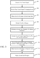
- FIG. 3 illustrates a method for controlling x-ray frame rate of an imaging system for a catheter procedure system in accordance with an example of the disclosure.
- controller 134 (shown in FIG. 2 ) generates a first control signal for the imaging system 104 (shown in FIGs. 1 and 2 ).
- the first control signal indicates a first frame rate (e.g., frames per second) for image acquisition by the imaging system 104.
- the first frame rate is a predetermined frame rate, for example, a standard frame rate for use unless, as described further below, the characteristics of the catheter procedure indicate a state where an alternative frame rate (e.g., lower or higher) may be used for image acquisition. In another embodiment, as discussed further below, the first frame rate is selected based on one or more parameters of the catheter procedure.
- controller 134 provides the first control signal to the imaging system 104 and, at block 306, the imaging system obtains a first set of images at the first frame rate.
- the first set of images may be displayed, according to an embodiment, using, for example, a display 120 or 122 of the catheter procedure system.
- the parameter of the catheter procedure is the speed of a percutaneous device being advanced through the vasculature of the patient by the catheter procedure system.
- the percutaneous device may be a guide wire and the parameter is the speed of the distal end or tip of the guide wire as it is moved within the patient.
- the second frame rate is selected to be a higher frame rate than the first frame rate or the same frame rate as the first frame rate. If the speed of the percutaneous device is faster than the predetermined threshold, the second frame is selected to be a lower frame rate than the first frame rate or the same frame rate as the first frame rate.
- the parameter of the catheter procedure is the magnification level selected by a user (e.g., using user interface 126) for viewing a region of interest of the images generated by the imaging system. If the magnification level is increased to "zoom-in" on a region of interest, e.g., the magnification level is selected to be greater than a predetermined magnification threshold, the second frame rate may be selected to be a higher frame rate than the first frame rate. If the magnification level is reduced to the predetermined magnification threshold or below the predetermined magnification threshold to "zoom-out", the second frame rate may be selected to be a lower or reduced frame rate than the first frame rate.
- the parameter is the location of a percutaneous device (or a selected portion of the percutaneous device) positioned within or being advanced through the vasculature by the catheter procedure system.
- the location of the percutaneous device may be determined using, for example, the images obtained by the imaging system either by a user or automatically using the controller of the catheter procedure system.
- the parameter is the location of the percutaneous device (or a selected portion of the percutaneous device) in relation to a region of interest (i.e., the proximity to or a distance between the percutaneous device and the region of interest) such as a lesion.
- a region 402 having a predetermined distance before and after a lesion 410 may be identified as shown in FIG. 4 .
- the second frame rate may be selected to be higher than the first frame rate.
- the parameter is the location of the percutaneous device (or a selected portion of the percutaneous device) in relation to the geometry of the vasculature such as, for example, the width of the lumen proximate to a distal end of the percutaneous device or the proximity of a distal end of the percutaneous device to a juncture in the vasculature. If the width of the vasculature proximate a distal end of, for example, a guide wire is greater than a predetermined width, then the second frame rate may be selected to be lower than the first frame rate.
- the second frame rate may be selected to be the same as or higher than the first frame rate.
- a path to a lesion 516 may pass through one or more junction points or junctures 510 in the coronary anatomy as shown in FIG. 5 .
- the distal end 504 of a percutaneous device for example, a guide wire 506, may be advanced down either a first lumen 512 or a second lumen 514. The distal end 504 of the guide wire 506 should be advanced through the proper lumen to reach the desired location, for example, lesion 516.
- the location of the distal end 504 of the guide wire 506 and the juncture 510 may be determined using, for example, the images obtained by the imaging system either by a user or automatically using the controller of the catheter procedure system. If the distal end 504 is located proximate to (e.g., at a predetermined distance from) the juncture 510, the second frame rate may be selected to be higher than the first frame rate. If the distal end 504 is not located within a predetermined distance from the juncture 510, the second frame rate may be selected to be the same as or lower than the first frame rate.
- the parameter of the catheter procedure is the location of a first percutaneous device in relation to a second percutaneous device. For example, the location of a guide wire within a guide catheter as the guide wire is navigated towards a lesion or other region of interest.
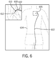
- FIG. 6 is a schematic of the placement of a guide catheter and a guide wire in the vasculature of a patient in accordance with an embodiment.
- a guide catheter 602 has been fed into the torso 604 of a patient to reach the cardiac region 606.
- a guide wire 608 Within the guide catheter 602 is a guide wire 608 which distal end or tip 610 has not yet passed out of the distal end 612 of the guide catheter 602.
- the images obtained by the imaging system may be used to identify the location of the guide wire 608 within the guide catheter 602 and monitor the progress of the guide wire 6087 as it passes through the guide catheter 602. If the guide wire 608 is located within the guide catheter and the distal end of 610 of the guide wire 608 has not yet passed out of the guide catheter 602, the second frame rate may be selected to be lower than the first frame rate.
- the parameter of the catheter procedure is a comparison of successive images obtained by the imaging system to identify, for example, movement of the vasculature (e.g., a beating heart) or if the percutaneous device is not moving or idle. If a selected portion of the percutaneous device (e.g., the distal end of a guide wire) is located within a region of moving vasculature, the second frame rate may be selected to be higher than the first frame rate. If the selected portion of the percutaneous device is not located within a region of moving vasculature, the second frame rate may be selected to be the same as or lower than the first frame rate. If the percutaneous device is idle, the second frame rate may be selected to be lower than the first frame rate.
- the vasculature e.g., a beating heart
- the controller 134 provides the second control signal to the imaging system at block 314 to adjust the first frame rate to the second frame rate.
- the imaging system obtains a second set of images at the second frame rate.
- the second set of images may be displayed, according to an embodiment, using, for example, a display 120 or 122 of the catheter procedure system.
- One or more of the parameters discussed above may be used to adjust the frame rate as the catheter procedure is performed and progresses through different states of the procedure (e.g., the advancement and location of the percutaneous device within the vasculature). By identifying when the frame rate may be reduced, the x-ray exposure or dose during the procedure may be reduced.
- Computer-executable instructions for controlling x-ray frame rate of an imaging system for a catheter procedure system may be stored on a form of computer readable media.
- Computer readable media includes volatile and nonvolatile, removable, and non-removable media implemented in any method or technology for storage of information such as computer readable instructions, data structures, program modules or other data.
- Computer readable media includes, but is not limited to, random access memory (RAM), read-only memory (ROM), electrically erasable programmable ROM (EEPROM), flash memory or other memory technology, compact disk ROM (CD-ROM), digital versatile disks (DVD) or other optical storage, magnetic cassettes, magnetic tape, magnetic disk storage or other magnetic storage devices, or any other medium which can be used to store the desired instructions and which may be accessed by system 10 (shown in FIG. 1 ), including by internet or other computer network form of access.
- RAM random access memory
- ROM read-only memory
- EEPROM electrically erasable programmable ROM
- flash memory or other memory technology
- CD-ROM compact disk ROM
- DVD digital versatile disks
- magnetic cassettes magnetic tape
- magnetic disk storage magnetic disk storage devices
Description
- The present disclosure relates generally to robotic catheter procedure systems and, in particular, to a system and method for controlling x-ray frame rate of an imaging system for a catheter procedure system.
- Catheters may be used for many medical procedures, including inserting a guide wire, delivering a stent and delivering and inflating a balloon. Catheterization procedures are commonly performed for diagnosis and treatment of diseases of the heart and vascular systems. The catheterization procedure is generally initiated by inserting a guide wire into a blood vessel in the patient's body. The guide wire is then advanced to the desired location, most commonly in one of the heart vessels or elsewhere in the vascular system. At this point, a catheter is slid over the guide wire into the blood vessel and/or heart. In some procedures, the catheter is a balloon catheter or stent delivery system that when deployed at the site of the lesion allows for increased blood flow through the portion of the coronary artery that is affected by the lesion.
- Robotic catheter procedure systems have been developed that may be used to aid a physician in performing a catheterization procedure such as a percutaneous coronary intervention (PCI). The physician uses a robotic system to precisely steer a coronary guide wire, balloon catheter or stent delivery system in order to, for example, widen an obstructed artery. In order to perform PCI, the distal tip of a guide wire must be navigated through coronary anatomy past a target lesion. While observing the coronary anatomy using fluoroscopy, the physician manipulates the proximal end of the guide wire in order to direct the distal tip into the appropriate vessels toward the lesion and avoid advancing into side branches. A fluoroscopy imaging system uses x-rays to obtain real-time images of the human vasculature and percutaneous devices within the vasculature. The frequency of images taken, or the frame rate (e.g., frames per second) effects the amount of radiation exposure or radiation dose for the patient and the medical professionals performing the catheter procedure. The frame rate can also affect the quality of the image acquired by the fluoroscopy system.
- It would be desirable to provide a system and method for controlling x-ray frame rate of an imaging system for a catheter procedure system to reduce the number of x-ray images taken to reduce the x-ray exposure and also to provide appropriate quality of images to perform the catheter procedure.
- Document
US2015005620 A1 discloses a bedside system in which the X-ray exposure of the patient may be reduced by taking intermittent fluoroscopic images and the frame rate may be selected in accordance with the velocity of feeding of a guide wire or working catheter. - In accordance with an example of the disclosure, a method for controlling x-ray frame rate of an imaging system for a catheter procedure system, includes generating a first control signal that indicates a first frame rate, providing the first control signal to an imaging system, obtaining a first set of images at the first frame rate, determining at least one parameter of a catheter procedure performed by the catheter procedure system, generating a second control signal based on the at least one parameter of the catheter procedure, the second control signal indicating second frame rate, providing the second control signal to the imaging system to adjust the first frame rate to the second frame rate, obtaining a second set of images at the second frame rate and displaying the second set of images on a display.
- In accordance with another embodiment, a catheter procedure system includes a bedside system having at least one percutaneous device and at least one drive mechanism coupled to the at least one percutaneous device, an imaging system; and a workstation coupled to the bed side system and the imaging system, the workstation having a user interface, at least one display, a controller coupled to the bedside system, the user interface, the at least one display and the imaging system, the controller programmed to generate a first control signal that indicates a first frame rate, provide the first control signal to the imaging system, determine at least one parameter of a catheter procedure performed by the catheter procedure system, generate a second control signal based on the at least one parameter of the catheter procedure, the second control signal indicating second frame rate and provide the second control signal to the imaging system to adjust the first frame rate to the second frame rate, wherein the imaging system is configured to obtain a first set of images at the first fame rate and to obtain a second set of images at the second frame rate.
- This application will become more fully understood from the following detailed description, taken in conjunction with the accompanying figures, wherein like reference numerals refer to like elements in which:
-
FIG. 1 is a perspective view of an exemplary catheter procedure system in accordance with an embodiment; -
FIG. 2 is a schematic block diagram of a catheter procedure system in accordance with an embodiment; -
FIG. 3 illustrates a method for controlling x-ray frame rate of an imaging system for a catheter procedure system in accordance with an example of the disclosure; -
FIG. 4 illustrates an exemplary path of a percutaneous device to a lesion in accordance with an embodiment; -
FIG. 5 illustrates an exemplary path of a percutaneous device to a lesion in accordance with an embodiment; and -
FIG. 6 is a schematic of the placement of a guide catheter and a guide wire in accordance with an embodiment. -
FIG. 1 is a perspective view of an exemplary catheter procedure system in accordance with an embodiment. InFIG. 1 , acatheter procedure system 100 may be used to perform catheter based medical procedures (e.g., a percutaneous intervention procedure). Catheter based medical procedures may include diagnostic catheterization procedures during which one or more catheters are used to aid in the diagnosis of a patient's disease. For example, during one embodiment of a catheter based diagnostic procedure, a contrast media is injected onto one or more coronary arteries through a catheter and an image of the patient's heart is taken. Catheter based medical procedures may also include catheter based therapeutic procedures (e.g., angioplasty, stent placement, treatment of peripheral vascular disease, etc.) during which a catheter is used to treat a disease. It should be noted, however, that one skilled in the art would recognize that certain specific percutaneous intervention devices or components (e.g., type of guide wire, type of catheter, etc.) will be selected based on the type of procedure that is to be performed.Catheter procedure system 100 is capable of performing any number of catheter based medical procedures with minor adjustments to accommodate the specific percutaneous intervention devices to be used in the procedure. In particular, while the embodiments ofcatheter procedure system 100 describe herein are explained primarily in relation to the treatment of coronary disease,catheter procedure system 100 may be used to diagnose and/or treat any type of disease or condition amenable to diagnosis and/or treatment via a catheter based procedure. -
Catheter procedure system 100 includeslab unit 106 andworkstation 116.Catheter procedure system 100 includes a robotic catheter system, shown asbedside system 110, located withinlab unit 106 adjacent apatient 102.Patient 102 is supported on a table 108. Generally,bedside system 110 may be equipped with the appropriate percutaneous intervention devices or other components (e.g., guide wires, guide catheters, working catheters such as balloon catheters and stent delivery systems, contrast media, medicine, diagnostic catheters, etc.) to allow the user to perform a catheter based medical procedure via a robotic system by operating various controls such as the controls located atworkstation 116.Bedside system 110 may include any number and/or combination of components to providebedside system 110 with the functionality described herein.Bedside system 110 includes, among other elements, a drive assembly 114 (e.g., that may contain a sterile, disposable portion) supported by arobotic arm 112 which may be used to automatically advance a guide wire into a guide catheter seated in an artery of thepatient 102. -
Bedside system 110 is in communication withworkstation 116, allowing signals generated by the user inputs ofworkstation 116 to be transmitted tobedside system 110 to control the various functions ofbedside system 110.Bedside system 110 may also provide feedback signals (e.g., operating conditions, warning signals, error codes, etc.) toworkstation 116.Bedside system 110 may be connected toworkstation 116 via a communication link 140 (shown inFIG. 2 ) that may be a wireless connection, cable connections, or any other means capable of allowing communication to occur betweenworkstation 116 andbedside system 110. -
Workstation 116 includes auser interface 126 configured to receive user inputs to operate various components or systems ofcatheter procedure system 100.User interface 126 includescontrols 118 that allow the user to controlbedside system 110 to perform a catheter based medical procedure. For example,controls 118 may be configured to causebedside system 110 to perform various tasks using the various percutaneous intervention devices with whichbedside system 110 may be equipped (e.g., to advance, retract, or rotate a guide wire, advance, retract or rotate a working catheter, advance, retract, or rotate a guide catheter, inflate or deflate a balloon located on a catheter, position and/or deploy a stent, inject contrast media into a catheter, inject medicine into a catheter, or to perform any other function that may be performed as part of a catheter based medical procedure).Drive assembly 114 includes various drive mechanisms to cause movement (e.g., axial and rotational movement) of the components of thebedside system 110 including the percutaneous devices. - In one embodiment,
controls 118 include atouch screen 124, one ormore joysticks 128 andbuttons joystick 128 may be configured to advance, retract, or rotate various components and percutaneous devices such as, for example, a guide wire, a guide catheter or a working catheter.Buttons bedside system 110. Multiplier button acts to increase or decrease the speed at which the associated component is moved in response to a manipulation ofcontrols 118. In one embodiment,controls 118 may include one or more controls or icons (not shown) displayed ontouch screen 124, that, when activated, causes operation of a component of thecatheter procedure system 100.Controls 118 may also include a balloon or stent control that is configured to inflate or deflate a balloon and/or a stent. Each of the controls may include one or more buttons, joysticks, touch screen, etc. that may be desirable to control the particular component to which the control is dedicated. In addition,touch screen 124 may display one or more icons (not shown) related to various portions ofcontrols 118 or to various components ofcatheter procedure system 100. -
User interface 126 may include a first monitor or display 120 and a second monitor or display 122.First monitor 120 andsecond monitor 122 may be configured to display information or patient specific data to the user located atworkstation 116. For example,first monitor 120 andsecond monitor 122 may be configured to display image data (e.g., x-ray images, MRI images, CT images, ultrasound images, etc.), hemodynamic data (e.g., blood pressure, heart rate, etc.), patient record information (e.g., medical history, age, weight, etc.). In addition,first monitor 120 andsecond monitor 122 may be configured to display procedure specific information (e.g., duration of procedure, catheter or guide wire position, volume of medicine or contrast agent delivered, etc.). Monitor 120 andmonitor 122 may be configured to display information regarding the position the guide catheter. Further, monitor 120 and monitor 122 may be configured to display information to provide the functionalities associated with controller 134 (shown inFIG. 2 ) discussed below. In another embodiment,user interface 126 includes a single screen of sufficient size to display one or more of the display components and/or touch screen components discussed herein. -
Catheter procedure system 100 also includes animaging system 104 located withinlab unit 106.Imaging system 104 may be any medical imaging system that may be used in conjunction with a catheter based medical procedure (e.g., non-digital x-ray, digital x-ray, CT, MRI, ultrasound, etc.). In an exemplary embodiment,imaging system 104 is a digital x-ray imaging device that is in communication withworkstation 116. In one embodiment,imaging system 104 may include a C-arm (not shown) that allowsimaging system 104 to partially or completely rotate aroundpatient 102 in order to obtain images at different angular positions relative to patient 102 (e.g., sagittal views, caudal views, anterior-posterior views, etc.). -
Imaging system 104 may be configured to take x-ray images of the appropriate area ofpatient 102 during a particular procedure. For example,imaging system 104 may be configured to take one or more x-ray images of the heart to diagnose a heart condition.Imaging system 104 may also be configured to take one or more x-ray images during a catheter based medical procedure (e.g., real time images) to assist the user ofworkstation 116 to properly position a guide wire, guide catheter, stent, etc. during the procedure. The image or images may be displayed onfirst monitor 120 and/orsecond monitor 122. In particular, images may be displayed onfirst monitor 120 and/orsecond monitor 122 to allow the user to, for example, accurately move a guide catheter into the proper position. - In addition, a user of
workstation 116 may be able to control the angular position ofimaging system 104 relative to the patient to obtain and display various views of the patient's heart onfirst monitor 120 and/orsecond monitor 122. Displaying different views at different portions of the procedure may aid the user ofworkstation 116 to properly move and position the percutaneous interventional devices within the 3D geometry of the patient's heart. In an embodiment,imaging system 104 may be a 2D imaging system. In another embodiment,imaging system 104 may be any 3D imaging modality such as an x-ray based computed tomography (CT) imaging device, a magnetic resonance imaging device, a 3D ultrasound imaging device, etc. In this embodiment, the image of the patient's heart that is displayed during the procedure may be a 3D image. In addition, controls 118 may also be configured to allow the user positioned atworkstation 116 to control various functions of imaging system 104 (e.g., image capture, magnification, collimation, c-arm positioning, etc.). - Referring to
FIG. 2 , a block diagram ofcatheter procedure system 100 is shown according to an exemplary embodiment.Catheter procedure system 100 may include a control system, shown ascontroller 134.Controller 134 may be part ofworkstation 116.Controller 134 may generally be an electronic control unit suitable to providecatheter procedure system 100 with the various functionalities described herein. For example,controller 134 may be an embedded system, a dedicated circuit, a general purpose system programed with the functionality described herein, etc.Controller 134 is in communication with one ormore bedside systems 110, controls 118, monitors 120 and 122,imaging system 104 and patient sensors 136 (e.g., electrocardiogram ("ECG") devices, electroencephalogram ("EEG") devices, blood pressure monitors, temperature monitors, heart rate monitors, respiratory monitors, etc.). In various embodiments,controller 134 is configured to generate control signals based on the user's interaction withcontrols 118 and/or based upon information accessible tocontroller 134 such that a medical procedure may be performed usingcatheter procedure system 100. In addition,controller 134 may be in communication with a hospital data management system orhospital network 142 and one or more additional output devices 138 (e.g., printer, disk drive, cd/dvd writer, etc.). - Communication between the various components of
catheter procedure system 100 may be accomplished via communication links 140.Communication links 140 may be dedicated wires or wireless connections.Communication links 140 may also represent communication over a network.Catheter procedure system 100 may be connected or configured to include any other systems and/or devices not explicitly shown. For example,catheter procedure system 100 may include IVUS systems, image processing engines, data storage and archive systems, automatic balloon and/or stent inflation systems, medicine injection systems, medicine tracking and/or logging systems, user logs, encryption systems, systems to restrict access or use ofcatheter procedure system 100, etc. - As mentioned above, the
controller 134 is in communication with theimaging system 104 andcontroller 134 may be used to control theimaging system 104. In one embodiment,controller 134 is configured to adjust the frame rate (e.g., x-ray frame rate) utilized byimaging system 104 based on various parameters or states of the catheter procedure being performed using thecatheter procedure system 100.FIG. 3 illustrates a method for controlling x-ray frame rate of an imaging system for a catheter procedure system in accordance with an example of the disclosure. Atblock 302, controller 134 (shown inFIG. 2 ) generates a first control signal for the imaging system 104 (shown inFIGs. 1 and2 ). The first control signal indicates a first frame rate (e.g., frames per second) for image acquisition by theimaging system 104. In one embodiment, the first frame rate is a predetermined frame rate, for example, a standard frame rate for use unless, as described further below, the characteristics of the catheter procedure indicate a state where an alternative frame rate (e.g., lower or higher) may be used for image acquisition. In another embodiment, as discussed further below, the first frame rate is selected based on one or more parameters of the catheter procedure. Atblock 304,controller 134 provides the first control signal to theimaging system 104 and, atblock 306, the imaging system obtains a first set of images at the first frame rate. Atblock 308, the first set of images may be displayed, according to an embodiment, using, for example, adisplay - At
block 310, at least one parameter of the catheter procedure is determined and, atblock 312, a second control signal is generated bycontroller 134 based on the at least one parameter to indicate a second frame rate for image acquisition by theimaging system 104. Accordingly, the frame rate utilized by the imaging system may be adjusted automatically based on the different states of the catheter procedure. In one embodiment, the parameter of the catheter procedure is the speed of a percutaneous device being advanced through the vasculature of the patient by the catheter procedure system. For example, the percutaneous device may be a guide wire and the parameter is the speed of the distal end or tip of the guide wire as it is moved within the patient. In one embodiment, if the speed of the percutaneous device is slower than a predetermined threshold, the second frame rate is selected to be a higher frame rate than the first frame rate or the same frame rate as the first frame rate. If the speed of the percutaneous device is faster than the predetermined threshold, the second frame is selected to be a lower frame rate than the first frame rate or the same frame rate as the first frame rate. - In another embodiment, the parameter of the catheter procedure is the magnification level selected by a user (e.g., using user interface 126) for viewing a region of interest of the images generated by the imaging system. If the magnification level is increased to "zoom-in" on a region of interest, e.g., the magnification level is selected to be greater than a predetermined magnification threshold, the second frame rate may be selected to be a higher frame rate than the first frame rate. If the magnification level is reduced to the predetermined magnification threshold or below the predetermined magnification threshold to "zoom-out", the second frame rate may be selected to be a lower or reduced frame rate than the first frame rate.
- In another embodiment, the parameter is the location of a percutaneous device (or a selected portion of the percutaneous device) positioned within or being advanced through the vasculature by the catheter procedure system. The location of the percutaneous device may be determined using, for example, the images obtained by the imaging system either by a user or automatically using the controller of the catheter procedure system. In one embodiment, the parameter is the location of the percutaneous device (or a selected portion of the percutaneous device) in relation to a region of interest (i.e., the proximity to or a distance between the percutaneous device and the region of interest) such as a lesion. For example, a
region 402 having a predetermined distance before and after alesion 410 may be identified as shown inFIG. 4 . When thedistal end 404 of, for example, aguide wire 406 is within theregion 402, the second frame rate may be selected to be higher than the first frame rate. In another embodiment, the parameter is the location of the percutaneous device (or a selected portion of the percutaneous device) in relation to the geometry of the vasculature such as, for example, the width of the lumen proximate to a distal end of the percutaneous device or the proximity of a distal end of the percutaneous device to a juncture in the vasculature. If the width of the vasculature proximate a distal end of, for example, a guide wire is greater than a predetermined width, then the second frame rate may be selected to be lower than the first frame rate. If the width of the vasculature proximate a distal end of the guide wire is led than a predetermined width, then the second frame rate may be selected to be the same as or higher than the first frame rate. In another example, a path to alesion 516 may pass through one or more junction points orjunctures 510 in the coronary anatomy as shown inFIG. 5 . Atjuncture 510, thedistal end 504 of a percutaneous device, for example, aguide wire 506, may be advanced down either afirst lumen 512 or asecond lumen 514. Thedistal end 504 of theguide wire 506 should be advanced through the proper lumen to reach the desired location, for example,lesion 516. The location of thedistal end 504 of theguide wire 506 and thejuncture 510 may be determined using, for example, the images obtained by the imaging system either by a user or automatically using the controller of the catheter procedure system. If thedistal end 504 is located proximate to (e.g., at a predetermined distance from) thejuncture 510, the second frame rate may be selected to be higher than the first frame rate. If thedistal end 504 is not located within a predetermined distance from thejuncture 510, the second frame rate may be selected to be the same as or lower than the first frame rate. - The parameter of the catheter procedure is the location of a first percutaneous device in relation to a second percutaneous device. For example, the location of a guide wire within a guide catheter as the guide wire is navigated towards a lesion or other region of interest.
FIG. 6 is a schematic of the placement of a guide catheter and a guide wire in the vasculature of a patient in accordance with an embodiment. InFIG. 6 , aguide catheter 602 has been fed into thetorso 604 of a patient to reach thecardiac region 606. Within theguide catheter 602 is aguide wire 608 which distal end ortip 610 has not yet passed out of thedistal end 612 of theguide catheter 602. The images obtained by the imaging system may be used to identify the location of theguide wire 608 within theguide catheter 602 and monitor the progress of the guide wire 6087 as it passes through theguide catheter 602. If theguide wire 608 is located within the guide catheter and the distal end of 610 of theguide wire 608 has not yet passed out of theguide catheter 602, the second frame rate may be selected to be lower than the first frame rate. - In another embodiment, the parameter of the catheter procedure is a comparison of successive images obtained by the imaging system to identify, for example, movement of the vasculature (e.g., a beating heart) or if the percutaneous device is not moving or idle. If a selected portion of the percutaneous device (e.g., the distal end of a guide wire) is located within a region of moving vasculature, the second frame rate may be selected to be higher than the first frame rate. If the selected portion of the percutaneous device is not located within a region of moving vasculature, the second frame rate may be selected to be the same as or lower than the first frame rate. If the percutaneous device is idle, the second frame rate may be selected to be lower than the first frame rate.
- Once the second frame rate is selected and the second control signal has been generated, the
controller 134 provides the second control signal to the imaging system atblock 314 to adjust the first frame rate to the second frame rate. Atblock 316, the imaging system obtains a second set of images at the second frame rate. Atblock 318, the second set of images may be displayed, according to an embodiment, using, for example, adisplay - Computer-executable instructions for controlling x-ray frame rate of an imaging system for a catheter procedure system according to the above-described method may be stored on a form of computer readable media. Computer readable media includes volatile and nonvolatile, removable, and non-removable media implemented in any method or technology for storage of information such as computer readable instructions, data structures, program modules or other data. Computer readable media includes, but is not limited to, random access memory (RAM), read-only memory (ROM), electrically erasable programmable ROM (EEPROM), flash memory or other memory technology, compact disk ROM (CD-ROM), digital versatile disks (DVD) or other optical storage, magnetic cassettes, magnetic tape, magnetic disk storage or other magnetic storage devices, or any other medium which can be used to store the desired instructions and which may be accessed by system 10 (shown in
FIG. 1 ), including by internet or other computer network form of access.
Claims (7)
- A catheter procedure system comprising:a bedside system comprising at least one percutaneous device and at least one drive mechanism coupled to the at least one percutaneous device;an imaging system; anda workstation coupled to the bed side system and the imaging system, the workstation comprising:a user interface;at least one display;a controller coupled to the bedside system, the user interface, the at least one display and the imaging system, the controller programmed to:generate a first control signal that indicates a first frame rate;provide the first control signal to the imaging system;determine at least one parameter of a catheter procedure performed by the catheter procedure system;generate a second control signal based on the at least one parameter of the catheter procedure, the second control signal indicating second frame rate; andprovide the second control signal to the imaging system to adjust the first frame rate to the second frame rate;wherein the imaging system is configured to obtain a first set of images at the first frame rate and to obtain a second set of images at the second frame rate;wherein the bedside system includes a first percutaneous device and a second percutaneous device and wherein the at least one parameter of the catheter procedure includes a position of the first percutaneous device in relation to the second percutaneous device.
- A catheter procedure system according to claim 1, wherein the imaging system is a fluoroscopy system.
- A catheter procedure system according to claim 1, wherein the second frame rate is lower than the first frame rate.
- A catheter procedure system according to claim 1, wherein the second frame rate is higher than the first frame rate.
- A catheter procedure system according to claim 1, wherein the at least one parameter further includes a magnification level of at least one image in the first set of images
- A catheter procedure system according to claim 1, wherein the at least one parameter of the catheter procedure further includes a location of a percutaneous device in relation to a geometry of a vasculature.
- A catheter procedure system according to claim 1, wherein the at least one parameter of the catheter procedure further includes motion of a region of a vasculature.
Priority Applications (1)
| Application Number | Priority Date | Filing Date | Title |
|---|---|---|---|
| EP20195773.5A EP3785638A1 (en) | 2015-12-15 | 2016-12-13 | System and method for controlling x-ray frame rate of an imaging system |
Applications Claiming Priority (2)
| Application Number | Priority Date | Filing Date | Title |
|---|---|---|---|
| US201562267692P | 2015-12-15 | 2015-12-15 | |
| PCT/US2016/066362 WO2017106177A1 (en) | 2015-12-15 | 2016-12-13 | System and method for controlling x-ray frame rate of an imaging system |
Related Child Applications (2)
| Application Number | Title | Priority Date | Filing Date |
|---|---|---|---|
| EP20195773.5A Division-Into EP3785638A1 (en) | 2015-12-15 | 2016-12-13 | System and method for controlling x-ray frame rate of an imaging system |
| EP20195773.5A Division EP3785638A1 (en) | 2015-12-15 | 2016-12-13 | System and method for controlling x-ray frame rate of an imaging system |
Publications (3)
| Publication Number | Publication Date |
|---|---|
| EP3389759A1 EP3389759A1 (en) | 2018-10-24 |
| EP3389759A4 EP3389759A4 (en) | 2019-08-14 |
| EP3389759B1 true EP3389759B1 (en) | 2020-10-28 |
Family
ID=59057444
Family Applications (2)
| Application Number | Title | Priority Date | Filing Date |
|---|---|---|---|
| EP20195773.5A Pending EP3785638A1 (en) | 2015-12-15 | 2016-12-13 | System and method for controlling x-ray frame rate of an imaging system |
| EP16876482.7A Active EP3389759B1 (en) | 2015-12-15 | 2016-12-13 | System and method for controlling x-ray frame rate of an imaging system |
Family Applications Before (1)
| Application Number | Title | Priority Date | Filing Date |
|---|---|---|---|
| EP20195773.5A Pending EP3785638A1 (en) | 2015-12-15 | 2016-12-13 | System and method for controlling x-ray frame rate of an imaging system |
Country Status (5)
| Country | Link |
|---|---|
| US (2) | US11304668B2 (en) |
| EP (2) | EP3785638A1 (en) |
| JP (1) | JP7159046B2 (en) |
| CN (1) | CN108778393B (en) |
| WO (1) | WO2017106177A1 (en) |
Families Citing this family (8)
| Publication number | Priority date | Publication date | Assignee | Title |
|---|---|---|---|---|
| CN108778393B (en) * | 2015-12-15 | 2022-04-29 | 科林达斯公司 | System and method for controlling X-ray frame rate of imaging system |
| GB2575795A (en) * | 2018-07-23 | 2020-01-29 | Medsolve Ltd | Imaging system for use in a fluoroscopy procedure |
| EP3616624B1 (en) * | 2018-08-28 | 2021-04-28 | Siemens Healthcare GmbH | Method for operating an x-ray device, x-ray device, computer program and electronically readable data carrier |
| WO2021014926A1 (en) * | 2019-07-25 | 2021-01-28 | 富士フイルム株式会社 | Ultrasonic diagnosis device and control method for ultrasonic diagnosis device |
| US11272995B2 (en) | 2019-08-15 | 2022-03-15 | Auris Health, Inc. | Axial motion drive devices, systems, and methods for a robotic medical system |
| JP7412180B2 (en) * | 2020-01-07 | 2024-01-12 | キヤノンメディカルシステムズ株式会社 | X-ray diagnostic equipment |
| US11523875B2 (en) * | 2020-04-06 | 2022-12-13 | Biosense Webster (Israel) Ltd. | Enhanced catheter navigation methods and apparatus |
| DE102021202293A1 (en) | 2021-03-09 | 2022-09-15 | Siemens Healthcare Gmbh | Method for determining an imaging parameter value for the control of a medical device when a first image data set is acquired |
Family Cites Families (38)
| Publication number | Priority date | Publication date | Assignee | Title |
|---|---|---|---|---|
| US5492131A (en) | 1994-09-06 | 1996-02-20 | Guided Medical Systems, Inc. | Servo-catheter |
| JPH09270955A (en) * | 1996-03-31 | 1997-10-14 | Shimadzu Corp | X-ray video equipment |
| DE19725137C2 (en) | 1997-06-13 | 2003-01-23 | Siemens Ag | Medical examination device with means for recording patient and / or device movements |
| US7766894B2 (en) | 2001-02-15 | 2010-08-03 | Hansen Medical, Inc. | Coaxial catheter system |
| DE10109586A1 (en) * | 2001-02-28 | 2002-09-05 | Philips Corp Intellectual Pty | Processing of digital X-ray images obtained using medical fluoroscopy in which a single high dose rate exposure is made in order to accurately identify main objects in low dose rate exposures using a pattern-matching algorithm |
| JP2003284716A (en) * | 2002-03-27 | 2003-10-07 | Toshiba Corp | Radiation diagnostic device and insertion body for therapy |
| US7894877B2 (en) | 2002-05-17 | 2011-02-22 | Case Western Reserve University | System and method for adjusting image parameters based on device tracking |
| US7769427B2 (en) * | 2002-07-16 | 2010-08-03 | Magnetics, Inc. | Apparatus and method for catheter guidance control and imaging |
| US20050238140A1 (en) * | 2003-08-20 | 2005-10-27 | Dan Hardesty | X-ray imaging system with automatic image resolution enhancement |
| JP2007513726A (en) * | 2003-12-16 | 2007-05-31 | コーニンクレッカ フィリップス エレクトロニクス エヌ ヴィ | Ultrasound imaging system with automatic control of penetration, resolution and frame rate |
| EP1769390B1 (en) | 2004-06-04 | 2014-12-03 | Stereotaxis, Inc. | User interface for remote control of medical devices |
| CN1301684C (en) * | 2005-04-15 | 2007-02-28 | 张迎光 | Matched guide wire and guide tube |
| US8257302B2 (en) | 2005-05-10 | 2012-09-04 | Corindus, Inc. | User interface for remote control catheterization |
| WO2008078254A1 (en) * | 2006-12-22 | 2008-07-03 | Koninklijke Philips Electronics N.V. | An imaging system with two imaging modalities |
| EP2129284A4 (en) | 2007-03-08 | 2012-11-28 | Sync Rx Ltd | Imaging and tools for use with moving organs |
| US20080287783A1 (en) | 2007-05-16 | 2008-11-20 | General Electric Company | System and method of tracking delivery of an imaging probe |
| WO2009023801A1 (en) | 2007-08-14 | 2009-02-19 | Hansen Medical, Inc. | Robotic instrument systems and methods utilizing optical fiber sensor |
| EP2160978A1 (en) * | 2008-09-05 | 2010-03-10 | General Electric Company | Method and apparatus for catheter guidance using a combination of ultrasound and x-ray imaging |
| US9974509B2 (en) * | 2008-11-18 | 2018-05-22 | Sync-Rx Ltd. | Image super enhancement |
| JP2011000369A (en) * | 2009-06-22 | 2011-01-06 | Toshiba Corp | X-ray diagnostic apparatus |
| JP5438424B2 (en) * | 2009-07-31 | 2014-03-12 | キヤノン株式会社 | Medical image photographing device and photographing method thereof |
| US8911360B2 (en) * | 2009-11-20 | 2014-12-16 | Given Imaging Ltd. | System and method for controlling power consumption of an in vivo device |
| US8265224B2 (en) * | 2010-01-12 | 2012-09-11 | Siemens Medical Solutions Usa, Inc. | System for adjusting angiographic X-ray imaging parameters based on image content |
| EP3583978A1 (en) | 2010-03-02 | 2019-12-25 | Corindus Inc. | Robotic catheter system with variable speed control |
| JP5725745B2 (en) | 2010-07-05 | 2015-05-27 | 株式会社東芝 | X-ray diagnostic apparatus and medical image diagnostic apparatus |
| MX2013004542A (en) | 2010-10-27 | 2013-07-03 | Koninkl Philips Electronics Nv | Adaptive imaging and frame rate optimizing based on real-time shape sensing of medical instruments. |
| EP2688632B1 (en) | 2011-03-22 | 2016-05-18 | Corindus Inc. | Robotic catheter system including imaging system control |
| JP5784351B2 (en) | 2011-04-22 | 2015-09-24 | 株式会社東芝 | X-ray diagnostic apparatus and image processing apparatus |
| CN104023625A (en) * | 2011-09-08 | 2014-09-03 | Apn健康有限责任公司 | R-wave detection method |
| BR112014011024A2 (en) * | 2011-11-10 | 2017-04-25 | Koninklijke Philips Nv | ultrasound imaging system for providing a three-dimensional image of a volume, method for providing a three-dimensional ultrasound image of a volume in which the volume must be scanned along multiple scanning lines, and computer program |
| CN104160695B (en) * | 2012-03-09 | 2017-04-26 | 富士胶片株式会社 | Radiography device, radiography system, and radiography device control method |
| WO2014081940A1 (en) * | 2012-11-21 | 2014-05-30 | Trustees Of Boston University | Tissue markers and uses thereof |
| US20140259439A1 (en) | 2013-03-15 | 2014-09-18 | Itaconix Corporation | Polycarboxylic Acid Polymers For Treatment of Leather |
| EP2991555B1 (en) * | 2013-04-03 | 2018-10-17 | Koninklijke Philips N.V. | Interventional x-ray system |
| US20150005745A1 (en) * | 2013-06-26 | 2015-01-01 | Corindus, Inc. | 3-d mapping for guidance of device advancement out of a guide catheter |
| KR102201407B1 (en) * | 2013-11-18 | 2021-01-12 | 삼성전자주식회사 | X-ray imaging apparatus and control method thereof |
| WO2015076551A1 (en) | 2013-11-19 | 2015-05-28 | Samsung Electronics Co., Ltd. | X-ray imaging apparatus and method of controlling the same |
| CN108778393B (en) * | 2015-12-15 | 2022-04-29 | 科林达斯公司 | System and method for controlling X-ray frame rate of imaging system |
-
2016
- 2016-12-13 CN CN201680074721.4A patent/CN108778393B/en active Active
- 2016-12-13 US US16/062,305 patent/US11304668B2/en active Active
- 2016-12-13 WO PCT/US2016/066362 patent/WO2017106177A1/en active Application Filing
- 2016-12-13 EP EP20195773.5A patent/EP3785638A1/en active Pending
- 2016-12-13 JP JP2018530847A patent/JP7159046B2/en active Active
- 2016-12-13 EP EP16876482.7A patent/EP3389759B1/en active Active
-
2022
- 2022-03-15 US US17/654,840 patent/US20220202381A1/en active Pending
Non-Patent Citations (1)
| Title |
|---|
| None * |
Also Published As
| Publication number | Publication date |
|---|---|
| US20180360398A1 (en) | 2018-12-20 |
| CN108778393B (en) | 2022-04-29 |
| JP7159046B2 (en) | 2022-10-24 |
| WO2017106177A1 (en) | 2017-06-22 |
| EP3785638A1 (en) | 2021-03-03 |
| CN108778393A (en) | 2018-11-09 |
| JP2019502444A (en) | 2019-01-31 |
| EP3389759A1 (en) | 2018-10-24 |
| US11304668B2 (en) | 2022-04-19 |
| US20220202381A1 (en) | 2022-06-30 |
| EP3389759A4 (en) | 2019-08-14 |
Similar Documents
| Publication | Publication Date | Title |
|---|---|---|
| US20220202381A1 (en) | System and Method for Controlling X-Ray Frame Rate of an Imaging System | |
| US20230112934A1 (en) | Device drive for catheter procedure system | |
| US20230310100A1 (en) | Robotic catheter system including imaging system control | |
| CN107205781B (en) | System and method for guiding a wire | |
| US20210353376A1 (en) | Interlocking system and method for joysticks in a catheter procedure system | |
| US11229490B2 (en) | System and method for monitoring of guide catheter seating | |
| JP6971861B2 (en) | Catheter treatment system | |
| JP2022515959A (en) | System and method to guide the device to the target position through the route | |
| US20220088349A1 (en) | Robotic catheter system with variable speed control | |
| US10912624B2 (en) | System and apparatus for sensing contact on a robotic mechanism in a catheter procedure system |
Legal Events
| Date | Code | Title | Description |
|---|---|---|---|
| STAA | Information on the status of an ep patent application or granted ep patent |
Free format text: STATUS: THE INTERNATIONAL PUBLICATION HAS BEEN MADE |
|
| PUAI | Public reference made under article 153(3) epc to a published international application that has entered the european phase |
Free format text: ORIGINAL CODE: 0009012 |
|
| STAA | Information on the status of an ep patent application or granted ep patent |
Free format text: STATUS: REQUEST FOR EXAMINATION WAS MADE |
|
| 17P | Request for examination filed |
Effective date: 20180616 |
|
| AK | Designated contracting states |
Kind code of ref document: A1 Designated state(s): AL AT BE BG CH CY CZ DE DK EE ES FI FR GB GR HR HU IE IS IT LI LT LU LV MC MK MT NL NO PL PT RO RS SE SI SK SM TR |
|
| AX | Request for extension of the european patent |
Extension state: BA ME |
|
| DAV | Request for validation of the european patent (deleted) | ||
| DAX | Request for extension of the european patent (deleted) | ||
| RIN1 | Information on inventor provided before grant (corrected) |
Inventor name: WENDEROW, TAL Inventor name: KOTTENSTETTE, NICHOLAS Inventor name: HANDLER, DAVID |
|
| A4 | Supplementary search report drawn up and despatched |
Effective date: 20190715 |
|
| RIC1 | Information provided on ipc code assigned before grant |
Ipc: A61B 6/00 20060101ALI20190709BHEP Ipc: A61M 25/01 20060101ALI20190709BHEP Ipc: A61M 25/09 20060101ALI20190709BHEP Ipc: A61B 34/30 20160101ALN20190709BHEP Ipc: A61B 6/12 20060101ALI20190709BHEP Ipc: A61B 90/00 20160101ALN20190709BHEP Ipc: A61B 17/00 20060101ALN20190709BHEP Ipc: A61M 5/00 20060101ALI20190709BHEP Ipc: A61B 34/00 20160101ALI20190709BHEP Ipc: A61M 31/00 20060101AFI20190709BHEP |
|
| GRAP | Despatch of communication of intention to grant a patent |
Free format text: ORIGINAL CODE: EPIDOSNIGR1 |
|
| STAA | Information on the status of an ep patent application or granted ep patent |
Free format text: STATUS: GRANT OF PATENT IS INTENDED |
|
| RIC1 | Information provided on ipc code assigned before grant |
Ipc: A61M 5/00 20060101ALI20200508BHEP Ipc: A61B 34/00 20160101ALI20200508BHEP Ipc: A61M 25/09 20060101ALI20200508BHEP Ipc: A61B 90/00 20160101ALN20200508BHEP Ipc: A61B 6/12 20060101ALI20200508BHEP Ipc: A61B 6/00 20060101ALI20200508BHEP Ipc: A61M 25/01 20060101ALI20200508BHEP Ipc: A61M 31/00 20060101AFI20200508BHEP Ipc: A61B 34/30 20160101ALN20200508BHEP Ipc: A61B 17/00 20060101ALN20200508BHEP |
|
| RIN1 | Information on inventor provided before grant (corrected) |
Inventor name: WENDEROW, TAL Inventor name: HANDLER, DAVID Inventor name: KOTTENSTETTE, NICHOLAS |
|
| INTG | Intention to grant announced |
Effective date: 20200529 |
|
| RAP1 | Party data changed (applicant data changed or rights of an application transferred) |
Owner name: CORINDUS, INC. |
|
| GRAS | Grant fee paid |
Free format text: ORIGINAL CODE: EPIDOSNIGR3 |
|
| GRAA | (expected) grant |
Free format text: ORIGINAL CODE: 0009210 |
|
| STAA | Information on the status of an ep patent application or granted ep patent |
Free format text: STATUS: THE PATENT HAS BEEN GRANTED |
|
| AK | Designated contracting states |
Kind code of ref document: B1 Designated state(s): AL AT BE BG CH CY CZ DE DK EE ES FI FR GB GR HR HU IE IS IT LI LT LU LV MC MK MT NL NO PL PT RO RS SE SI SK SM TR |
|
| REG | Reference to a national code |
Ref country code: GB Ref legal event code: FG4D |
|
| REG | Reference to a national code |
Ref country code: CH Ref legal event code: EP |
|
| REG | Reference to a national code |
Ref country code: DE Ref legal event code: R096 Ref document number: 602016046908 Country of ref document: DE Ref country code: DE Ref legal event code: R081 Ref document number: 602016046908 Country of ref document: DE Owner name: CORINDUS, INC., WALTHAM, US Free format text: FORMER OWNER: CORINDUS INC., WALTHAM, MA, US Ref country code: DE Ref legal event code: R082 Ref document number: 602016046908 Country of ref document: DE Representative=s name: MAIER, DANIEL OLIVER, DIPL.-ING. UNIV., DE Ref country code: DE Ref legal event code: R082 Ref document number: 602016046908 Country of ref document: DE Representative=s name: LORENZ & KOLLEGEN PATENTANWAELTE PARTNERSCHAFT, DE |
|
| REG | Reference to a national code |
Ref country code: AT Ref legal event code: REF Ref document number: 1327592 Country of ref document: AT Kind code of ref document: T Effective date: 20201115 |
|
| REG | Reference to a national code |
Ref country code: IE Ref legal event code: FG4D |
|
| REG | Reference to a national code |
Ref country code: DE Ref legal event code: R082 Ref document number: 602016046908 Country of ref document: DE Ref country code: DE Ref legal event code: R082 Ref document number: 602016046908 Country of ref document: DE Representative=s name: MAIER, DANIEL OLIVER, DIPL.-ING. UNIV., DE |
|
| REG | Reference to a national code |
Ref country code: NL Ref legal event code: FP |
|
| REG | Reference to a national code |
Ref country code: AT Ref legal event code: MK05 Ref document number: 1327592 Country of ref document: AT Kind code of ref document: T Effective date: 20201028 |
|
| PG25 | Lapsed in a contracting state [announced via postgrant information from national office to epo] |
Ref country code: FI Free format text: LAPSE BECAUSE OF FAILURE TO SUBMIT A TRANSLATION OF THE DESCRIPTION OR TO PAY THE FEE WITHIN THE PRESCRIBED TIME-LIMIT Effective date: 20201028 Ref country code: GR Free format text: LAPSE BECAUSE OF FAILURE TO SUBMIT A TRANSLATION OF THE DESCRIPTION OR TO PAY THE FEE WITHIN THE PRESCRIBED TIME-LIMIT Effective date: 20210129 Ref country code: PT Free format text: LAPSE BECAUSE OF FAILURE TO SUBMIT A TRANSLATION OF THE DESCRIPTION OR TO PAY THE FEE WITHIN THE PRESCRIBED TIME-LIMIT Effective date: 20210301 Ref country code: RS Free format text: LAPSE BECAUSE OF FAILURE TO SUBMIT A TRANSLATION OF THE DESCRIPTION OR TO PAY THE FEE WITHIN THE PRESCRIBED TIME-LIMIT Effective date: 20201028 Ref country code: NO Free format text: LAPSE BECAUSE OF FAILURE TO SUBMIT A TRANSLATION OF THE DESCRIPTION OR TO PAY THE FEE WITHIN THE PRESCRIBED TIME-LIMIT Effective date: 20210128 |
|
| REG | Reference to a national code |
Ref country code: DE Ref legal event code: R082 Ref document number: 602016046908 Country of ref document: DE Representative=s name: MAIER, DANIEL OLIVER, DIPL.-ING. UNIV., DE |
|
| REG | Reference to a national code |
Ref country code: LT Ref legal event code: MG4D |
|
| PG25 | Lapsed in a contracting state [announced via postgrant information from national office to epo] |
Ref country code: SE Free format text: LAPSE BECAUSE OF FAILURE TO SUBMIT A TRANSLATION OF THE DESCRIPTION OR TO PAY THE FEE WITHIN THE PRESCRIBED TIME-LIMIT Effective date: 20201028 Ref country code: IS Free format text: LAPSE BECAUSE OF FAILURE TO SUBMIT A TRANSLATION OF THE DESCRIPTION OR TO PAY THE FEE WITHIN THE PRESCRIBED TIME-LIMIT Effective date: 20210228 Ref country code: PL Free format text: LAPSE BECAUSE OF FAILURE TO SUBMIT A TRANSLATION OF THE DESCRIPTION OR TO PAY THE FEE WITHIN THE PRESCRIBED TIME-LIMIT Effective date: 20201028 Ref country code: LV Free format text: LAPSE BECAUSE OF FAILURE TO SUBMIT A TRANSLATION OF THE DESCRIPTION OR TO PAY THE FEE WITHIN THE PRESCRIBED TIME-LIMIT Effective date: 20201028 Ref country code: BG Free format text: LAPSE BECAUSE OF FAILURE TO SUBMIT A TRANSLATION OF THE DESCRIPTION OR TO PAY THE FEE WITHIN THE PRESCRIBED TIME-LIMIT Effective date: 20210128 Ref country code: ES Free format text: LAPSE BECAUSE OF FAILURE TO SUBMIT A TRANSLATION OF THE DESCRIPTION OR TO PAY THE FEE WITHIN THE PRESCRIBED TIME-LIMIT Effective date: 20201028 Ref country code: AT Free format text: LAPSE BECAUSE OF FAILURE TO SUBMIT A TRANSLATION OF THE DESCRIPTION OR TO PAY THE FEE WITHIN THE PRESCRIBED TIME-LIMIT Effective date: 20201028 |
|
| PG25 | Lapsed in a contracting state [announced via postgrant information from national office to epo] |
Ref country code: HR Free format text: LAPSE BECAUSE OF FAILURE TO SUBMIT A TRANSLATION OF THE DESCRIPTION OR TO PAY THE FEE WITHIN THE PRESCRIBED TIME-LIMIT Effective date: 20201028 |
|
| REG | Reference to a national code |
Ref country code: DE Ref legal event code: R097 Ref document number: 602016046908 Country of ref document: DE |
|
| PG25 | Lapsed in a contracting state [announced via postgrant information from national office to epo] |
Ref country code: SK Free format text: LAPSE BECAUSE OF FAILURE TO SUBMIT A TRANSLATION OF THE DESCRIPTION OR TO PAY THE FEE WITHIN THE PRESCRIBED TIME-LIMIT Effective date: 20201028 Ref country code: RO Free format text: LAPSE BECAUSE OF FAILURE TO SUBMIT A TRANSLATION OF THE DESCRIPTION OR TO PAY THE FEE WITHIN THE PRESCRIBED TIME-LIMIT Effective date: 20201028 Ref country code: EE Free format text: LAPSE BECAUSE OF FAILURE TO SUBMIT A TRANSLATION OF THE DESCRIPTION OR TO PAY THE FEE WITHIN THE PRESCRIBED TIME-LIMIT Effective date: 20201028 Ref country code: CZ Free format text: LAPSE BECAUSE OF FAILURE TO SUBMIT A TRANSLATION OF THE DESCRIPTION OR TO PAY THE FEE WITHIN THE PRESCRIBED TIME-LIMIT Effective date: 20201028 Ref country code: LT Free format text: LAPSE BECAUSE OF FAILURE TO SUBMIT A TRANSLATION OF THE DESCRIPTION OR TO PAY THE FEE WITHIN THE PRESCRIBED TIME-LIMIT Effective date: 20201028 Ref country code: SM Free format text: LAPSE BECAUSE OF FAILURE TO SUBMIT A TRANSLATION OF THE DESCRIPTION OR TO PAY THE FEE WITHIN THE PRESCRIBED TIME-LIMIT Effective date: 20201028 |
|
| REG | Reference to a national code |
Ref country code: CH Ref legal event code: PL |
|
| PG25 | Lapsed in a contracting state [announced via postgrant information from national office to epo] |
Ref country code: DK Free format text: LAPSE BECAUSE OF FAILURE TO SUBMIT A TRANSLATION OF THE DESCRIPTION OR TO PAY THE FEE WITHIN THE PRESCRIBED TIME-LIMIT Effective date: 20201028 Ref country code: MC Free format text: LAPSE BECAUSE OF FAILURE TO SUBMIT A TRANSLATION OF THE DESCRIPTION OR TO PAY THE FEE WITHIN THE PRESCRIBED TIME-LIMIT Effective date: 20201028 |
|
| PLBE | No opposition filed within time limit |
Free format text: ORIGINAL CODE: 0009261 |
|
| REG | Reference to a national code |
Ref country code: BE Ref legal event code: MM Effective date: 20201231 |
|
| STAA | Information on the status of an ep patent application or granted ep patent |
Free format text: STATUS: NO OPPOSITION FILED WITHIN TIME LIMIT |
|
| 26N | No opposition filed |
Effective date: 20210729 |
|
| PG25 | Lapsed in a contracting state [announced via postgrant information from national office to epo] |
Ref country code: AL Free format text: LAPSE BECAUSE OF FAILURE TO SUBMIT A TRANSLATION OF THE DESCRIPTION OR TO PAY THE FEE WITHIN THE PRESCRIBED TIME-LIMIT Effective date: 20201028 Ref country code: LU Free format text: LAPSE BECAUSE OF NON-PAYMENT OF DUE FEES Effective date: 20201213 |
|
| PG25 | Lapsed in a contracting state [announced via postgrant information from national office to epo] |
Ref country code: SI Free format text: LAPSE BECAUSE OF FAILURE TO SUBMIT A TRANSLATION OF THE DESCRIPTION OR TO PAY THE FEE WITHIN THE PRESCRIBED TIME-LIMIT Effective date: 20201028 Ref country code: CH Free format text: LAPSE BECAUSE OF NON-PAYMENT OF DUE FEES Effective date: 20201231 Ref country code: LI Free format text: LAPSE BECAUSE OF NON-PAYMENT OF DUE FEES Effective date: 20201231 |
|
| PG25 | Lapsed in a contracting state [announced via postgrant information from national office to epo] |
Ref country code: IS Free format text: LAPSE BECAUSE OF FAILURE TO SUBMIT A TRANSLATION OF THE DESCRIPTION OR TO PAY THE FEE WITHIN THE PRESCRIBED TIME-LIMIT Effective date: 20210228 Ref country code: TR Free format text: LAPSE BECAUSE OF FAILURE TO SUBMIT A TRANSLATION OF THE DESCRIPTION OR TO PAY THE FEE WITHIN THE PRESCRIBED TIME-LIMIT Effective date: 20201028 Ref country code: MT Free format text: LAPSE BECAUSE OF FAILURE TO SUBMIT A TRANSLATION OF THE DESCRIPTION OR TO PAY THE FEE WITHIN THE PRESCRIBED TIME-LIMIT Effective date: 20201028 Ref country code: CY Free format text: LAPSE BECAUSE OF FAILURE TO SUBMIT A TRANSLATION OF THE DESCRIPTION OR TO PAY THE FEE WITHIN THE PRESCRIBED TIME-LIMIT Effective date: 20201028 |
|
| PG25 | Lapsed in a contracting state [announced via postgrant information from national office to epo] |
Ref country code: MK Free format text: LAPSE BECAUSE OF FAILURE TO SUBMIT A TRANSLATION OF THE DESCRIPTION OR TO PAY THE FEE WITHIN THE PRESCRIBED TIME-LIMIT Effective date: 20201028 |
|
| PG25 | Lapsed in a contracting state [announced via postgrant information from national office to epo] |
Ref country code: BE Free format text: LAPSE BECAUSE OF NON-PAYMENT OF DUE FEES Effective date: 20201231 |
|
| PGFP | Annual fee paid to national office [announced via postgrant information from national office to epo] |
Ref country code: DE Payment date: 20220620 Year of fee payment: 7 |
|
| PGFP | Annual fee paid to national office [announced via postgrant information from national office to epo] |
Ref country code: GB Payment date: 20230103 Year of fee payment: 7 |
|
| PGFP | Annual fee paid to national office [announced via postgrant information from national office to epo] |
Ref country code: NL Payment date: 20231215 Year of fee payment: 8 Ref country code: IT Payment date: 20231220 Year of fee payment: 8 Ref country code: IE Payment date: 20231220 Year of fee payment: 8 Ref country code: FR Payment date: 20231214 Year of fee payment: 8 |