EP4005095B1 - Funkfrequenzübertragungsvorrichtung und verfahren zur steuerung solch einer vorrichtung - Google Patents
Funkfrequenzübertragungsvorrichtung und verfahren zur steuerung solch einer vorrichtung Download PDFInfo
- Publication number
- EP4005095B1 EP4005095B1 EP20739718.3A EP20739718A EP4005095B1 EP 4005095 B1 EP4005095 B1 EP 4005095B1 EP 20739718 A EP20739718 A EP 20739718A EP 4005095 B1 EP4005095 B1 EP 4005095B1
- Authority
- EP
- European Patent Office
- Prior art keywords
- cell
- cells
- circuit
- transmission
- output
- Prior art date
- Legal status (The legal status is an assumption and is not a legal conclusion. Google has not performed a legal analysis and makes no representation as to the accuracy of the status listed.)
- Active
Links
Images

Classifications
-
- H—ELECTRICITY
- H04—ELECTRIC COMMUNICATION TECHNIQUE
- H04B—TRANSMISSION
- H04B1/00—Details of transmission systems, not covered by a single one of groups H04B3/00 - H04B13/00; Details of transmission systems not characterised by the medium used for transmission
- H04B1/02—Transmitters
- H04B1/04—Circuits
- H04B1/0483—Transmitters with multiple parallel paths
-
- H—ELECTRICITY
- H04—ELECTRIC COMMUNICATION TECHNIQUE
- H04B—TRANSMISSION
- H04B1/00—Details of transmission systems, not covered by a single one of groups H04B3/00 - H04B13/00; Details of transmission systems not characterised by the medium used for transmission
- H04B1/02—Transmitters
- H04B1/04—Circuits
Definitions
- the present description relates generally to radiofrequency emission devices. It relates more particularly to a radio frequency transmission device comprising a plurality of elementary transmission cells, and to a method for controlling such a device.
- Each elementary transmission cell conventionally comprises a transmission circuit and an antenna connected to an output terminal of the transmission circuit.
- the output nodes of the power detectors of the different elementary cells are electrically isolated from each other.
- control circuit is configured to, in step b), compare the signal read in step a) with a predetermined threshold.
- control circuit is configured to implement, after step a), the following step: a′) simultaneously activate the second cell in transmission, deactivate the first cell in transmission, and read on the output node of the power detector of the first cell a signal representative of a radio frequency power received on the output terminal of the first cell via the antenna of the first cell.
- control circuit is further configured to, after step a′), compare the signal read in step a′) with the signal read in step a).
- control circuit is configured to repeat steps a) and b) for all the combinations of two cells of said plurality of cells.
- the power detector in each cell, is adapted to provide on its output node a signal representative of the average of the square of the voltage present on the output terminal of the transmission circuit of the cell.
- the transmission circuit comprises a radiofrequency signal generator and an amplifier connecting an output node of the generator to the output terminal of the transmission circuit.
- the radiofrequency signal generator comprises a local oscillator and a mixer suitable for modulating an output signal from the local oscillator.
- the cells of the plurality of cells are mounted on the same printed circuit board.
- the output nodes of the power detectors of the different elementary cells are electrically isolated from each other
- radio frequency signals or waves By radio frequency signals or waves is meant here radio signals or waves whose spectrum is between 3 kHz and 300 GHz.
- the embodiments described are very particularly advantageous for devices intended to transmit at millimeter wavelengths, for example at frequencies comprised between 30 and 300 GHz.
- FIG. 1 is a simplified electrical diagram of an example of a radio frequency transmission device 100 according to one embodiment.
- the device 100 of the figure 1 is for example intended to be used to locally irradiate the skin of a user, for medical or comfort purposes.
- the device 100 of the figure 1 comprises n elementary transmission cells C_i, with n integer greater than or equal to 2 and i integer ranging from 1 to n.
- the n cells C_i of the device 100 are for example identical (except for manufacturing dispersions).
- Each cell C_i comprises a transmission circuit 110 and an antenna 130 connected to an output terminal S of the transmission circuit 110.
- Each transmission circuit 110 is for example integrated in an elementary semiconductor chip specific to the cell, to which is connected the antenna 130 of the cell.
- the n cells C_i are for example mounted on the same printed circuit board.
- each transmission circuit 110 comprises a radiofrequency signal generator 112 suitable for supplying a radiofrequency signal to an output node n1.
- Each circuit 110 further comprises a power amplifier 114 (PA) having an input node connected, for example connected, to the output node n1 of the generator 112, and an output node connected, for example connected, to the terminal of output S of circuit 110.
- PA power amplifier
- Amplifier 114 is adapted to amplify the radiofrequency signal supplied by generator 112 with a view to its transmission by antenna 130.
- generator 112 comprises at least one local oscillator 116 providing an oscillating signal at a frequency of the order of the central transmission frequency of the cell, for example a frequency of between 30 and 300 GHz, for example a frequency of the order of 60 GHz.
- Each generator 112 can further comprise a mixer 118 adapted to modulate the signal supplied by the oscillator 116.
- the mixer 118 comprises an input node e1 connected, for example connected, to a node output of the oscillator 116, and an output node connected, for example connected, to the output node n1 of the generator 112.
- the mixer 118 further comprises an input node e2 intended to receive a modulation signal.
- the radiofrequency signal supplied at the output of mixer 118 then corresponds to the signal supplied by local oscillator 116, modulated by the signal applied to input e2 of mixer 118.
- the modulation signal applied to node e2 is a binary periodic signal or square-wave signal
- the mixer 118 transmitting the output signal of the oscillator 116 substantially identically to the node n1 when the modulation signal is in a first state, for example a high state, and not supplying any signal to node n1 when the modulation signal is in a second state, for example a low state.
- mixer 118 behaves like a switch controlled by the modulation signal applied to node e2.
- the frequency of the modulation signal is between 100 and 10000 Hz, for example of the order of 1000 Hz.
- the duty cycle of the modulation signal can be adjusted to control the average power of the radiofrequency signal delivered by the cell C_i.
- each transmission circuit 110 further comprises a specific power detector 120 (PD) having an input node linked, for example connected, to the output terminal S of the circuit 110.
- the power detector 120 is adapted to provide, on an output node s1, a signal (for example a DC voltage) representative of the power of the radio frequency signal delivered by the circuit 110 on its output terminal S.
- a signal for example a DC voltage
- the power detectors 120 of the different cells are distinct from each other and have respective output nodes isolated from each other.
- circuit 120 is configured to provide on its node s1 a signal based solely on a measurement of the voltage present on output terminal S of circuit 110.
- circuit 120 is configured to provide on its node s1 a signal representative of the amplitude of the envelope of the voltage present on the output terminal S of the circuit 110.
- the circuit 120 is configured to provide on its node s1 a signal representative of the average of the square of the voltage present on the output terminal S of the circuit 110.
- the power detector circuit 120 makes it possible to know the power of the radiofrequency signal actually emitted towards the outside of the cell, which can vary significantly depending on the environment of the cell. In normal operation, feedback can be provided to adapt a transmission power setpoint of the circuit 110 of the cell, as a function of the power measurement supplied by the power detector circuit 120 of the cell. In addition or alternatively, in each cell C_i, the power detector circuit 120 can be used during a cell test phase, to detect a possible failure of the cell, for example a mismatch of impedance between the transmission circuit 110 and the antenna 130 of the cell, or a connection fault between the transmission circuit 110 and the antenna 130 of the cell.
- the device 100 further comprises a control circuit 140 (CTRL).
- Circuit 140 may include a microcontroller.
- control circuit 140 is entirely analog.
- the control circuit 140 comprises n input terminals linked, for example connected, respectively to the n output nodes s1 of the power detector circuits 120 of the n cells C_i of the device.
- the control circuit 140 is adapted to read and process the output signals from the power detectors 120 of the cells C_i.
- the control circuit 140 is further adapted to control the activation/deactivation in transmission of the cells C_i and/or to control the average transmission power of the cells C_i.
- the control circuit 140 can be adapted to supply, via n distinct output terminals, not detailed in the figure, the n modulation signals applied to the input terminals e2 of the mixers 118 of the n cells C_i of the device.
- the device 100 can be controlled, via the control circuit 140, so that the n elementary emission cells C_i of the device simultaneously emit radio frequency signals.
- the radiofrequency power detected on the terminal S of the second cell by sound detector power 120 is representative of the radiofrequency power received via the antenna 130 of the second cell, coming from the first cell.
- the output signal of the power detector 120 of the inactive cell in transmission is compared with one or more thresholds to determine information as to the state of the device or of its environment.
- the aforementioned mode of operation can for example be used to test the operation of the elementary cells of the device and in particular the state of the connections between the transmission circuits 110 and the antennas 130 of the cells of the device.
- provision can be made, during a test phase, to activate a single first cell of the device in transmission, and to compare the output signal of the power detector 120 of a second cell to a predetermined threshold. cell of the device, distinct from the first cell. If the output signal of the power detector 120 of the second cell is greater than the threshold, it can be deduced that the first and second cells are functional, and in particular that the quality of the connections between the transmission circuit 110 and the antenna 130 of each of the first and second cells is satisfactory.
- At least one of the first and second cells has a fault, for example a connection fault between the transmission circuit 110 and the antenna 130 of the cell.
- An alert can then for example be transmitted to a user of the device, by means of a non-detailed user interface.
- the test can then be repeated sequentially for one or more other pairs of cells of the device, for example for all the combinations of two cells of the device, so as to test all the cells of the device, and, if necessary, locate the faulty cells.
- the aforementioned mode of operation can be used to determine information about the environment of the device 100, for example properties of the medium surrounding the device 100.
- the power detected by the power detector 120 of the inactive cell in transmission, or receiving cell depends on the properties of the transmission channel separating the antenna of the receiving cell from the antenna of the active cell in transmission, or transmitting cell, and, more generally, on the properties of the immediate environment of the two antennas.
- the aforementioned mode of operation can be used to determine information as to the level of humidity of the skin, information which can for example be used to estimate the emotional state of the user and adapt the radio frequency power emitted by the device accordingly.
- differential measurements can be implemented. For example, for each pair of cells tested, a first measurement can be made by simultaneously activating a first cell of the pair in transmission and the second cell of the pair in reception, then a second measurement by simultaneously activating the second cell in transmission. cell of the pair and in reception the first cell of the pair. The two measures can then be compared to refine the accuracy of the information determined.
- a mapping of the transmissions for all the pairs of cells of the device can be established.
- a processing of these transmission data can be implemented by the control circuit 140, for example by a tomography method, so as to provide information on the state of the environment of the device at several points, or the localization faults in the device.
- FIG. 2 illustrates an example of a method for controlling a radio frequency transmitting device of the type described in relation to the figure 1 , during a test phase of the state of the device or its environment.
- the other cells of the device can be deactivated in transmission and in reception.
- the process of picture 2 further comprises, after step 201, a step 202 (STEP2) during which the signal read in step 201 at the output of the power detector 120 of the second cell is analyzed by an electronic processing device, for example the control circuit 140 of the device 100, to deduce therefrom information as to the state of the device 100 or of its environment.
- a step 202 (STEP2) during which the signal read in step 201 at the output of the power detector 120 of the second cell is analyzed by an electronic processing device, for example the control circuit 140 of the device 100, to deduce therefrom information as to the state of the device 100 or of its environment.
- the output signal of the power detector 120 of the second cell can for example be compared with one or more predetermined thresholds.
- Steps 201 and 202 can be repeated for different pairs of cells of the device, for example for all combinations of two cells of the device.
- the steps 201 and 202 can be repeated a plurality of times by modifying at each iteration the transmission frequency and/or the transmission power, so as to scan a plurality of transmission frequencies. and/or a plurality of distinct transmit powers.
- the aforementioned method can be used to adjust the transmission parameters, in particular the transmission frequency and/or the transmission power of the cell activated in transmission.
- provision may be made to seek, by successive iterations, settings tending towards obtaining a maximum ratio between the power detected by the power detection circuit of the cell deactivated in transmission and the power emitted by the cell activated in transmission.
- the embodiments described are not limited to the examples of elementary radiofrequency emission cells described in relation to the figure 1 . It will be noted in particular that depending on the application considered, the mixers 118 of the transmission circuits 110 of the cells of the figure 1 can be omitted, the output of the local oscillator 116 of each cell then being directly connected to the input of the power amplifier 114 of the cell.
- the activation/deactivation in transmission of an elementary cell C_i can be carried out by acting on the modulation signal applied to the input e2 of the transmission circuit 110 of the cell .
- the embodiments described are not limited to this particular case. More generally, the cells C_i can be equipped with any other transmission activation/deactivation means controllable via the control circuit 140.
- the embodiments described are not limited to the examples described in which the detector power 120 of each cell measures the radio frequency power on the output terminal S of the cell from the sole measurement of the voltage on the terminal S of the cell. More generally, any known power detector circuit can be used to measure the radiofrequency power on the S output terminal of each cell, for example a circuit based on voltage and current measurements on the S terminal.
- information can also be deduced from the analysis of the output signal of the power detector of a cell activated in transmission.
- the analysis of an output signal from the power detector 120 of a cell activated in transmission can allow, by comparison with predetermined reference signals, for example signals stored during a preliminary calibration phase, to obtain information about the environment of this cell.
- predetermined reference signals for example signals stored during a preliminary calibration phase
- the analysis of the output signal from the power detector of a cell activated in emission can for example make it possible to determine whether the device is correctly applied against the skin.
- the measurement of the output signal of the power detector of a cell activated in transmission can be repeated a plurality of times by controlling the cell activated in transmission to scan a plurality of transmission frequencies and/or or a plurality of distinct transmit powers.
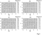
- FIG. 3 represents, by way of illustrative example, output signals from the power detector of a cell activated in transmission in four distinct configurations (A), (B), (C) and (D).
- A emission frequency
- B emission frequency
- VB bias voltage
- the configuration (A) of the picture 3 corresponds to a case in which the emission device is intact and surrounded by air.
- the configuration (B) of the picture 3 corresponds to a case in which the antenna 130 of the transmission cell considered has been removed.
- the configuration (C) of the picture 3 corresponds to a case in which the emission device is intact and correctly applied against the skin of a user.
- the configuration (D) of the picture 3 corresponds to a case in which the emission device is intact and applied against a metal plate.
- the response of the cell power detector varies according to the conditions of use of the device.
- predetermined reference signatures for example generated by learning during a preliminary calibration phase
- a feedback can be provided to adapt a frequency setpoint and/or transmission power of the circuit 110 of the cell, depending on the power measurement provided by its power detector circuit 120.
- the analysis of the output signals from the power detector of a cell activated in emission can also make it possible to determine information as to the emotional state of the subject, which influences the electrical conductivity of his skin, as described in particular in the article entitled " Human sweat ducts as helical antennas in the sub-THz frequency range-an overview" by A. Kochnev et al. (IEEE Transactions on Terahertz Science and Technology, Vol 11, N°2, June 2018 ).
Landscapes
- Engineering & Computer Science (AREA)
- Computer Networks & Wireless Communication (AREA)
- Signal Processing (AREA)
- Transmitters (AREA)
- Mobile Radio Communication Systems (AREA)
Claims (12)
- Funkübertragungsvorrichtung (100), die eine Vielzahl von Elementarzellen (C_i) aufweist, die jeweils eine Übertragungsschaltung (110) und eine Antenne (130), die mit einem Ausgangsanschluss (S) der Übertragungsschaltung verbunden ist, aufweisen, wobei jede Übertragungsschaltung (110) einen Leistungsdetektor (120) aufweist, der für die Zelle spezifisch ist, mit einem Eingangsknoten, der mit dem Ausgangsanschluss (S) der Zellübertragungsschaltung (110) gekoppelt ist, und einen Ausgangsknoten (s1), der für die Zelle spezifisch ist, wobei die Vorrichtung ferner eine Steuerschaltung (140) aufweist, die konfiguriert ist, während einer Betriebsphase die folgenden Schritte zu implementieren:a) gleichzeitiges Aktivieren bei Übertragung einer ersten Zelle der Vielzahl von Zellen, Deaktivieren bei Übertragung einer zweiten Zelle der Vielzahl von Zellen und Lesen aus dem Ausgangsknoten (s1) des Leistungsdetektors (120) der zweiten Zelle eines Signals, das für eine Funkfrequenzleistung repräsentativ ist, die am Ausgangsanschluss (S) der zweiten Zelle über die Antenne (130) der zweiten Zelle empfangen wird; undb) Ableiten aus dem Signal, das in Schritt a) gelesen wurde, von Information in Bezug auf den Zustand der Vorrichtung (100) oder ihrer Umgebung,wobei die Information, die im Schritt b) abgeleitet wurde, eine Leistungsübertragung zwischen den Antennen der ersten und zweiten Zelle charakterisiert.
- Vorrichtung nach Anspruch 1, wobei die Ausgangsknoten (s1) der Leistungsdetektoren (120) der verschiedenen Elementarzellen (C_i) elektrisch voneinander isoliert sind.
- Vorrichtung (100) nach Anspruch 1 oder 2, wobei die Steuerschaltung (140) konfiguriert ist zum Vergleichen, in Schritt b), des Signals, das in Schritt a) gelesen wurde, mit einem vorgegebenen Schwellenwert.
- Vorrichtung (100) nach einem der Ansprüche 1 bis 3, wobei die Steuerschaltung (140) konfiguriert ist, zum Implementieren, nach Schritt a), des folgenden Schritts:
a') gleichzeitiges Aktivieren bei Übertragung der zweiten Zelle, Deaktivieren bei Übertragung der ersten Zelle und Lesen vom Ausgangsknoten (s1) des Leistungsdetektors (120) der ersten Zelle eines Signals, das für eine Funkfrequenzleistung repräsentativ ist, die am Ausgangsanschluss (S) der ersten Zelle über die Antenne (130) der ersten Zelle empfangen wird. - Vorrichtung (100) nach Anspruch 4, wobei die Steuerschaltung (140) ferner konfiguriert ist, zum Vergleichen, nach Schritt a'), des Signals, das in Schritt a') gelesen wurde, mit dem Signal das in Schritt a) gelesen wurde.
- Vorrichtung (100) nach einem der Ansprüche 1 bis 5, wobei die Steuerschaltung (140) konfiguriert ist, zum Wiederholen der Schritte a) und b) für alle Kombinationen von zwei Zellen (C_i) der Vielzahl von Zellen.
- Vorrichtung (100) nach einem der Ansprüche 1 bis 6, wobei in jeder Zelle (C_i) der Leistungsdetektor (120) eingerichtet ist, zum Liefern, an seinem Ausgangsknoten (s1), eines Signals, das für den Durchschnitt des Quadrats der Spannung repräsentativ ist, die am Ausgangsanschluss (S) der Übertragungsschaltung (110) der Zelle anliegt.
- Vorrichtung (100) nach einem der Ansprüche 1 bis 7, wobei in jeder Zelle (C_i) die Übertragungsschaltung (110) einen Funkfrequenz-Signalgenerator (112) und einen Verstärker (114) aufweist, der einen Ausgangsknoten (n1) des Generators (112) mit dem Ausgangsanschluss (S) der Übertragungsschaltung (110) verbindet.
- Vorrichtung (100) nach Anspruch 8, wobei in jeder Zelle (C_i) der Funkfrequenz-Signalgenerator (112) einen lokalen Oszillator (116) und einen Mischer aufweist, der eingerichtet ist zum Modulieren eines Ausgangssignals des lokalen Oszillators (116).
- Vorrichtung (100) nach einem der Ansprüche 1 bis 9, wobei die Zellen (C_i) der Vielzahl von Zellen auf einer gleichen Leiterplatte montiert sind.
- Verfahren zur Steuerung einer Funkübertragungsvorrichtung (100), die eine Vielzahl von Elementarzellen (C_i) aufweist, von denen jede eine Übertragungsschaltung (110) und eine Antenne (130) aufweist, die mit einem Ausgangsanschluss (S) der Übertragungsschaltung verbunden ist, wobei jede Übertragungsschaltung (110) einen Leistungsdetektor (120) aufweist, der für die Zelle spezifisch ist mit einem Eingangsknoten, der mit dem Ausgangsanschluss (S) der Übertragungsschaltung (110) gekoppelt ist, und einen Ausgangsknoten (s1), der für die Zelle spezifisch ist, wobei das Verfahren die folgenden Schritte aufweist:a) gleichzeitiges Aktivieren bei Übertragung einer ersten Zelle der Vielzahl von Zellen, Deaktivieren bei Übertragung einer zweiten Zelle der Vielzahl von Zellen und Lesen aus dem Ausgangsknoten (s1) des Leistungsdetektors (120) der zweiten Zelle eines Signals, das für eine Funkfrequenzleistung repräsentativ ist, die am Ausgangsanschluss (S) der zweiten Zelle über die Antenne (130) der zweiten Zelle empfangen wird; undb) Ableiten aus dem Signal, das in Schritt a) gelesen wurde, von Information in Bezug auf den Zustand der Vorrichtung (100) oder ihrer Umgebung,wobei die Information, die im Schritt b) abgeleitet wurde, eine Leistungsübertragung zwischen den Antennen der ersten und zweiten Zelle charakterisiert.
- Verfahren nach Anspruch 11, wobei die Ausgangsknoten (s1) der Leistungsdetektoren (120) der verschiedenen Elementarzellen (C_i) elektrisch voneinander isoliert sind.
Applications Claiming Priority (2)
| Application Number | Priority Date | Filing Date | Title |
|---|---|---|---|
| FR1908690A FR3099668B1 (fr) | 2019-07-30 | 2019-07-30 | Dispositif d'émission radiofréquence et procédé de commande d'un tel dispositif |
| PCT/EP2020/070263 WO2021018631A1 (fr) | 2019-07-30 | 2020-07-17 | Dispositif d'emission radiofrequence et procede de commande d'un tel dispositif |
Publications (2)
| Publication Number | Publication Date |
|---|---|
| EP4005095A1 EP4005095A1 (de) | 2022-06-01 |
| EP4005095B1 true EP4005095B1 (de) | 2023-08-30 |
Family
ID=69024315
Family Applications (1)
| Application Number | Title | Priority Date | Filing Date |
|---|---|---|---|
| EP20739718.3A Active EP4005095B1 (de) | 2019-07-30 | 2020-07-17 | Funkfrequenzübertragungsvorrichtung und verfahren zur steuerung solch einer vorrichtung |
Country Status (4)
| Country | Link |
|---|---|
| US (1) | US12155403B2 (de) |
| EP (1) | EP4005095B1 (de) |
| FR (1) | FR3099668B1 (de) |
| WO (1) | WO2021018631A1 (de) |
Family Cites Families (7)
| Publication number | Priority date | Publication date | Assignee | Title |
|---|---|---|---|---|
| SE513156C2 (sv) * | 1998-07-10 | 2000-07-17 | Ericsson Telefon Ab L M | Anordning och förfarande relaterande till radiokommunikation |
| JP5933471B2 (ja) * | 2013-03-14 | 2016-06-08 | パナソニック株式会社 | フェーズドアレイ送信装置 |
| JP6379891B2 (ja) * | 2014-09-05 | 2018-08-29 | 富士通株式会社 | 位相調整装置、位相差検出装置及び位相調整方法 |
| JP6234360B2 (ja) * | 2014-12-24 | 2017-11-22 | 三菱電機株式会社 | アレイアンテナ装置及び校正方法 |
| US9722713B2 (en) * | 2015-06-26 | 2017-08-01 | Intel IP Corporation | Architecture and control of analog self-interference cancellation |
| US10917051B2 (en) * | 2017-06-30 | 2021-02-09 | Intel Corporation | Wireless architectures and digital pre-distortion (DPD) techniques using closed loop feedback for phased array transmitters |
| US11165397B2 (en) * | 2019-01-30 | 2021-11-02 | Skyworks Solutions, Inc. | Apparatus and methods for true power detection |
-
2019
- 2019-07-30 FR FR1908690A patent/FR3099668B1/fr not_active Expired - Fee Related
-
2020
- 2020-07-17 US US17/630,864 patent/US12155403B2/en active Active
- 2020-07-17 WO PCT/EP2020/070263 patent/WO2021018631A1/fr not_active Ceased
- 2020-07-17 EP EP20739718.3A patent/EP4005095B1/de active Active
Also Published As
| Publication number | Publication date |
|---|---|
| US20220302938A1 (en) | 2022-09-22 |
| EP4005095A1 (de) | 2022-06-01 |
| FR3099668B1 (fr) | 2022-07-29 |
| US12155403B2 (en) | 2024-11-26 |
| WO2021018631A1 (fr) | 2021-02-04 |
| FR3099668A1 (fr) | 2021-02-05 |
Similar Documents
| Publication | Publication Date | Title |
|---|---|---|
| EP2567478B1 (de) | System und verfahren zur simulation elektromagnetischer umgebungen mit einer anordnung einschliesslich einer vielzahl von sonden | |
| US10505275B2 (en) | System and method for near field test of active antenna system (ASS)transceiver | |
| US7362266B2 (en) | Mutual coupling method for calibrating a phased array | |
| EP0977304A1 (de) | Kommunikationsgerät, mobiles Funkgerät, Basisstation und verfahren zur steuerung der Leistungsverstärkung | |
| CN113206697A (zh) | 一种宽带射频接收处理系统装置及其自检方法 | |
| EP3121902A1 (de) | Funkvorrichtung zum senden/empfangen von funkwellen, und entsprechendes höhenmessungsfunksystem | |
| EP2706676A1 (de) | Verfahren zur Kennzeichnung einer Übertragungsantenne eines Satelliten auf seiner Umlaufbahn und Anordnung dafür | |
| EP3234638A1 (de) | Verfahren zur bestimmung von parametern eines kompressionsfilters und zugehöriges mehrkanalradar | |
| EP3182588B1 (de) | Automatische anpassung der impedanz eines funkempfängers | |
| EP4005095A1 (de) | Funkfrequenzübertragungsvorrichtung und verfahren zur steuerung solch einer vorrichtung | |
| Paulino et al. | Human activity recognition with a 6.5 ghz reconfigurable intelligent surface for wi-fi 6e | |
| Tekbıyık et al. | Graph attention network-based single-pixel compressive direction of arrival estimation | |
| EP1291974B1 (de) | Effizientes Hochleistungsantennensystem | |
| WO2023180344A2 (en) | Device and method for hybrid rf-optical multi-beamforming using correlation-based evm metrics | |
| Nielsen et al. | Remote diagnosis of fault element in active phased arrays using deep neural network | |
| FR3103338A1 (fr) | Procede de configuration d’un reseau d’antennes actives et réseau d’antennes actives configure selon ledit procede | |
| CN212572522U (zh) | 信号源和测试系统 | |
| TWI847639B (zh) | 基於近場到遠場轉換的天線場型的測量裝置和測量方法 | |
| Zhang et al. | RIS-aided communications at 3.5 GHz: Some insights from practical measurement results | |
| FR3106240A1 (fr) | Système antennaire à rayonnement contrôlé | |
| Yaghjian | Simplified approach to probe-corrected spherical near-field scanning | |
| Hoogelander et al. | Over-the-air characterization techniques for antenna-coupled direct-detectors at terahertz frequencies | |
| RU2716269C1 (ru) | Радиофотонный передающий тракт для передачи мощных широкополосных сигналов и эффективного возбуждения антенн | |
| EP0293287B1 (de) | Testeinrichtung für einen Phasendemodulator mit Spreizspektrum | |
| Buch et al. | Verification of maxSNR Method for Egmrt Experimental Aperture Array Beamformer |
Legal Events
| Date | Code | Title | Description |
|---|---|---|---|
| STAA | Information on the status of an ep patent application or granted ep patent |
Free format text: STATUS: UNKNOWN |
|
| STAA | Information on the status of an ep patent application or granted ep patent |
Free format text: STATUS: THE INTERNATIONAL PUBLICATION HAS BEEN MADE |
|
| PUAI | Public reference made under article 153(3) epc to a published international application that has entered the european phase |
Free format text: ORIGINAL CODE: 0009012 |
|
| STAA | Information on the status of an ep patent application or granted ep patent |
Free format text: STATUS: REQUEST FOR EXAMINATION WAS MADE |
|
| 17P | Request for examination filed |
Effective date: 20220112 |
|
| AK | Designated contracting states |
Kind code of ref document: A1 Designated state(s): AL AT BE BG CH CY CZ DE DK EE ES FI FR GB GR HR HU IE IS IT LI LT LU LV MC MK MT NL NO PL PT RO RS SE SI SK SM TR |
|
| DAV | Request for validation of the european patent (deleted) | ||
| DAX | Request for extension of the european patent (deleted) | ||
| GRAP | Despatch of communication of intention to grant a patent |
Free format text: ORIGINAL CODE: EPIDOSNIGR1 |
|
| STAA | Information on the status of an ep patent application or granted ep patent |
Free format text: STATUS: GRANT OF PATENT IS INTENDED |
|
| INTG | Intention to grant announced |
Effective date: 20230228 |
|
| GRAS | Grant fee paid |
Free format text: ORIGINAL CODE: EPIDOSNIGR3 |
|
| GRAA | (expected) grant |
Free format text: ORIGINAL CODE: 0009210 |
|
| STAA | Information on the status of an ep patent application or granted ep patent |
Free format text: STATUS: THE PATENT HAS BEEN GRANTED |
|
| AK | Designated contracting states |
Kind code of ref document: B1 Designated state(s): AL AT BE BG CH CY CZ DE DK EE ES FI FR GB GR HR HU IE IS IT LI LT LU LV MC MK MT NL NO PL PT RO RS SE SI SK SM TR |
|
| REG | Reference to a national code |
Ref country code: GB Ref legal event code: FG4D Free format text: NOT ENGLISH |
|
| REG | Reference to a national code |
Ref country code: CH Ref legal event code: EP |
|
| REG | Reference to a national code |
Ref country code: DE Ref legal event code: R096 Ref document number: 602020016749 Country of ref document: DE |
|
| REG | Reference to a national code |
Ref country code: IE Ref legal event code: FG4D Free format text: LANGUAGE OF EP DOCUMENT: FRENCH |
|
| REG | Reference to a national code |
Ref country code: LT Ref legal event code: MG9D |
|
| REG | Reference to a national code |
Ref country code: NL Ref legal event code: MP Effective date: 20230830 |
|
| REG | Reference to a national code |
Ref country code: AT Ref legal event code: MK05 Ref document number: 1606735 Country of ref document: AT Kind code of ref document: T Effective date: 20230830 |
|
| PG25 | Lapsed in a contracting state [announced via postgrant information from national office to epo] |
Ref country code: GR Free format text: LAPSE BECAUSE OF FAILURE TO SUBMIT A TRANSLATION OF THE DESCRIPTION OR TO PAY THE FEE WITHIN THE PRESCRIBED TIME-LIMIT Effective date: 20231201 |
|
| PG25 | Lapsed in a contracting state [announced via postgrant information from national office to epo] |
Ref country code: IS Free format text: LAPSE BECAUSE OF FAILURE TO SUBMIT A TRANSLATION OF THE DESCRIPTION OR TO PAY THE FEE WITHIN THE PRESCRIBED TIME-LIMIT Effective date: 20231230 |
|
| PG25 | Lapsed in a contracting state [announced via postgrant information from national office to epo] |
Ref country code: SE Free format text: LAPSE BECAUSE OF FAILURE TO SUBMIT A TRANSLATION OF THE DESCRIPTION OR TO PAY THE FEE WITHIN THE PRESCRIBED TIME-LIMIT Effective date: 20230830 Ref country code: RS Free format text: LAPSE BECAUSE OF FAILURE TO SUBMIT A TRANSLATION OF THE DESCRIPTION OR TO PAY THE FEE WITHIN THE PRESCRIBED TIME-LIMIT Effective date: 20230830 Ref country code: NO Free format text: LAPSE BECAUSE OF FAILURE TO SUBMIT A TRANSLATION OF THE DESCRIPTION OR TO PAY THE FEE WITHIN THE PRESCRIBED TIME-LIMIT Effective date: 20231130 Ref country code: LV Free format text: LAPSE BECAUSE OF FAILURE TO SUBMIT A TRANSLATION OF THE DESCRIPTION OR TO PAY THE FEE WITHIN THE PRESCRIBED TIME-LIMIT Effective date: 20230830 Ref country code: LT Free format text: LAPSE BECAUSE OF FAILURE TO SUBMIT A TRANSLATION OF THE DESCRIPTION OR TO PAY THE FEE WITHIN THE PRESCRIBED TIME-LIMIT Effective date: 20230830 Ref country code: IS Free format text: LAPSE BECAUSE OF FAILURE TO SUBMIT A TRANSLATION OF THE DESCRIPTION OR TO PAY THE FEE WITHIN THE PRESCRIBED TIME-LIMIT Effective date: 20231230 Ref country code: HR Free format text: LAPSE BECAUSE OF FAILURE TO SUBMIT A TRANSLATION OF THE DESCRIPTION OR TO PAY THE FEE WITHIN THE PRESCRIBED TIME-LIMIT Effective date: 20230830 Ref country code: GR Free format text: LAPSE BECAUSE OF FAILURE TO SUBMIT A TRANSLATION OF THE DESCRIPTION OR TO PAY THE FEE WITHIN THE PRESCRIBED TIME-LIMIT Effective date: 20231201 Ref country code: FI Free format text: LAPSE BECAUSE OF FAILURE TO SUBMIT A TRANSLATION OF THE DESCRIPTION OR TO PAY THE FEE WITHIN THE PRESCRIBED TIME-LIMIT Effective date: 20230830 Ref country code: AT Free format text: LAPSE BECAUSE OF FAILURE TO SUBMIT A TRANSLATION OF THE DESCRIPTION OR TO PAY THE FEE WITHIN THE PRESCRIBED TIME-LIMIT Effective date: 20230830 |
|
| PG25 | Lapsed in a contracting state [announced via postgrant information from national office to epo] |
Ref country code: PL Free format text: LAPSE BECAUSE OF FAILURE TO SUBMIT A TRANSLATION OF THE DESCRIPTION OR TO PAY THE FEE WITHIN THE PRESCRIBED TIME-LIMIT Effective date: 20230830 Ref country code: NL Free format text: LAPSE BECAUSE OF FAILURE TO SUBMIT A TRANSLATION OF THE DESCRIPTION OR TO PAY THE FEE WITHIN THE PRESCRIBED TIME-LIMIT Effective date: 20230830 |
|
| PG25 | Lapsed in a contracting state [announced via postgrant information from national office to epo] |
Ref country code: ES Free format text: LAPSE BECAUSE OF FAILURE TO SUBMIT A TRANSLATION OF THE DESCRIPTION OR TO PAY THE FEE WITHIN THE PRESCRIBED TIME-LIMIT Effective date: 20230830 |
|
| PG25 | Lapsed in a contracting state [announced via postgrant information from national office to epo] |
Ref country code: SM Free format text: LAPSE BECAUSE OF FAILURE TO SUBMIT A TRANSLATION OF THE DESCRIPTION OR TO PAY THE FEE WITHIN THE PRESCRIBED TIME-LIMIT Effective date: 20230830 Ref country code: RO Free format text: LAPSE BECAUSE OF FAILURE TO SUBMIT A TRANSLATION OF THE DESCRIPTION OR TO PAY THE FEE WITHIN THE PRESCRIBED TIME-LIMIT Effective date: 20230830 Ref country code: ES Free format text: LAPSE BECAUSE OF FAILURE TO SUBMIT A TRANSLATION OF THE DESCRIPTION OR TO PAY THE FEE WITHIN THE PRESCRIBED TIME-LIMIT Effective date: 20230830 Ref country code: EE Free format text: LAPSE BECAUSE OF FAILURE TO SUBMIT A TRANSLATION OF THE DESCRIPTION OR TO PAY THE FEE WITHIN THE PRESCRIBED TIME-LIMIT Effective date: 20230830 Ref country code: DK Free format text: LAPSE BECAUSE OF FAILURE TO SUBMIT A TRANSLATION OF THE DESCRIPTION OR TO PAY THE FEE WITHIN THE PRESCRIBED TIME-LIMIT Effective date: 20230830 Ref country code: CZ Free format text: LAPSE BECAUSE OF FAILURE TO SUBMIT A TRANSLATION OF THE DESCRIPTION OR TO PAY THE FEE WITHIN THE PRESCRIBED TIME-LIMIT Effective date: 20230830 Ref country code: SK Free format text: LAPSE BECAUSE OF FAILURE TO SUBMIT A TRANSLATION OF THE DESCRIPTION OR TO PAY THE FEE WITHIN THE PRESCRIBED TIME-LIMIT Effective date: 20230830 Ref country code: PT Free format text: LAPSE BECAUSE OF FAILURE TO SUBMIT A TRANSLATION OF THE DESCRIPTION OR TO PAY THE FEE WITHIN THE PRESCRIBED TIME-LIMIT Effective date: 20240102 |
|
| PG25 | Lapsed in a contracting state [announced via postgrant information from national office to epo] |
Ref country code: IT Free format text: LAPSE BECAUSE OF FAILURE TO SUBMIT A TRANSLATION OF THE DESCRIPTION OR TO PAY THE FEE WITHIN THE PRESCRIBED TIME-LIMIT Effective date: 20230830 |
|
| REG | Reference to a national code |
Ref country code: DE Ref legal event code: R097 Ref document number: 602020016749 Country of ref document: DE |
|
| PLBE | No opposition filed within time limit |
Free format text: ORIGINAL CODE: 0009261 |
|
| STAA | Information on the status of an ep patent application or granted ep patent |
Free format text: STATUS: NO OPPOSITION FILED WITHIN TIME LIMIT |
|
| PG25 | Lapsed in a contracting state [announced via postgrant information from national office to epo] |
Ref country code: SI Free format text: LAPSE BECAUSE OF FAILURE TO SUBMIT A TRANSLATION OF THE DESCRIPTION OR TO PAY THE FEE WITHIN THE PRESCRIBED TIME-LIMIT Effective date: 20230830 |
|
| 26N | No opposition filed |
Effective date: 20240603 |
|
| PG25 | Lapsed in a contracting state [announced via postgrant information from national office to epo] |
Ref country code: BG Free format text: LAPSE BECAUSE OF FAILURE TO SUBMIT A TRANSLATION OF THE DESCRIPTION OR TO PAY THE FEE WITHIN THE PRESCRIBED TIME-LIMIT Effective date: 20230830 |
|
| PG25 | Lapsed in a contracting state [announced via postgrant information from national office to epo] |
Ref country code: BG Free format text: LAPSE BECAUSE OF FAILURE TO SUBMIT A TRANSLATION OF THE DESCRIPTION OR TO PAY THE FEE WITHIN THE PRESCRIBED TIME-LIMIT Effective date: 20230830 |
|
| PG25 | Lapsed in a contracting state [announced via postgrant information from national office to epo] |
Ref country code: MC Free format text: LAPSE BECAUSE OF FAILURE TO SUBMIT A TRANSLATION OF THE DESCRIPTION OR TO PAY THE FEE WITHIN THE PRESCRIBED TIME-LIMIT Effective date: 20230830 |
|
| REG | Reference to a national code |
Ref country code: CH Ref legal event code: PL |
|
| PG25 | Lapsed in a contracting state [announced via postgrant information from national office to epo] |
Ref country code: LU Free format text: LAPSE BECAUSE OF NON-PAYMENT OF DUE FEES Effective date: 20240717 |
|
| GBPC | Gb: european patent ceased through non-payment of renewal fee |
Effective date: 20240717 |
|
| PG25 | Lapsed in a contracting state [announced via postgrant information from national office to epo] |
Ref country code: LU Free format text: LAPSE BECAUSE OF NON-PAYMENT OF DUE FEES Effective date: 20240717 |
|
| PG25 | Lapsed in a contracting state [announced via postgrant information from national office to epo] |
Ref country code: BE Free format text: LAPSE BECAUSE OF NON-PAYMENT OF DUE FEES Effective date: 20240731 Ref country code: CH Free format text: LAPSE BECAUSE OF NON-PAYMENT OF DUE FEES Effective date: 20240731 |
|
| PG25 | Lapsed in a contracting state [announced via postgrant information from national office to epo] |
Ref country code: GB Free format text: LAPSE BECAUSE OF NON-PAYMENT OF DUE FEES Effective date: 20240717 |
|
| REG | Reference to a national code |
Ref country code: BE Ref legal event code: MM Effective date: 20240731 |
|
| PG25 | Lapsed in a contracting state [announced via postgrant information from national office to epo] |
Ref country code: IE Free format text: LAPSE BECAUSE OF NON-PAYMENT OF DUE FEES Effective date: 20240717 |
|
| PGFP | Annual fee paid to national office [announced via postgrant information from national office to epo] |
Ref country code: DE Payment date: 20250722 Year of fee payment: 6 |
|
| PGFP | Annual fee paid to national office [announced via postgrant information from national office to epo] |
Ref country code: FR Payment date: 20250722 Year of fee payment: 6 |
|
| PG25 | Lapsed in a contracting state [announced via postgrant information from national office to epo] |
Ref country code: CY Free format text: LAPSE BECAUSE OF FAILURE TO SUBMIT A TRANSLATION OF THE DESCRIPTION OR TO PAY THE FEE WITHIN THE PRESCRIBED TIME-LIMIT; INVALID AB INITIO Effective date: 20200717 |
|
| PG25 | Lapsed in a contracting state [announced via postgrant information from national office to epo] |
Ref country code: HU Free format text: LAPSE BECAUSE OF FAILURE TO SUBMIT A TRANSLATION OF THE DESCRIPTION OR TO PAY THE FEE WITHIN THE PRESCRIBED TIME-LIMIT; INVALID AB INITIO Effective date: 20200717 |