EP4004366B1 - Structure de support pour une nacelle d'une éolienne - Google Patents
Structure de support pour une nacelle d'une éolienne Download PDFInfo
- Publication number
- EP4004366B1 EP4004366B1 EP20763990.7A EP20763990A EP4004366B1 EP 4004366 B1 EP4004366 B1 EP 4004366B1 EP 20763990 A EP20763990 A EP 20763990A EP 4004366 B1 EP4004366 B1 EP 4004366B1
- Authority
- EP
- European Patent Office
- Prior art keywords
- connection
- support structure
- connection arrangement
- main foundation
- rear end
- Prior art date
- Legal status (The legal status is an assumption and is not a legal conclusion. Google has not performed a legal analysis and makes no representation as to the accuracy of the status listed.)
- Active
Links
Images





Classifications
-
- F—MECHANICAL ENGINEERING; LIGHTING; HEATING; WEAPONS; BLASTING
- F03—MACHINES OR ENGINES FOR LIQUIDS; WIND, SPRING, OR WEIGHT MOTORS; PRODUCING MECHANICAL POWER OR A REACTIVE PROPULSIVE THRUST, NOT OTHERWISE PROVIDED FOR
- F03D—WIND MOTORS
- F03D13/00—Assembly, mounting or commissioning of wind motors; Arrangements specially adapted for transporting wind motor components
- F03D13/20—Arrangements for mounting or supporting wind motors; Masts or towers for wind motors
-
- F—MECHANICAL ENGINEERING; LIGHTING; HEATING; WEAPONS; BLASTING
- F03—MACHINES OR ENGINES FOR LIQUIDS; WIND, SPRING, OR WEIGHT MOTORS; PRODUCING MECHANICAL POWER OR A REACTIVE PROPULSIVE THRUST, NOT OTHERWISE PROVIDED FOR
- F03D—WIND MOTORS
- F03D80/00—Details, components or accessories not provided for in groups F03D1/00 - F03D17/00
-
- F—MECHANICAL ENGINEERING; LIGHTING; HEATING; WEAPONS; BLASTING
- F05—INDEXING SCHEMES RELATING TO ENGINES OR PUMPS IN VARIOUS SUBCLASSES OF CLASSES F01-F04
- F05B—INDEXING SCHEME RELATING TO WIND, SPRING, WEIGHT, INERTIA OR LIKE MOTORS, TO MACHINES OR ENGINES FOR LIQUIDS COVERED BY SUBCLASSES F03B, F03D AND F03G
- F05B2240/00—Components
- F05B2240/10—Stators
- F05B2240/14—Casings, housings, nacelles, gondels or the like, protecting or supporting assemblies there within
-
- F—MECHANICAL ENGINEERING; LIGHTING; HEATING; WEAPONS; BLASTING
- F05—INDEXING SCHEMES RELATING TO ENGINES OR PUMPS IN VARIOUS SUBCLASSES OF CLASSES F01-F04
- F05B—INDEXING SCHEME RELATING TO WIND, SPRING, WEIGHT, INERTIA OR LIKE MOTORS, TO MACHINES OR ENGINES FOR LIQUIDS COVERED BY SUBCLASSES F03B, F03D AND F03G
- F05B2250/00—Geometry
- F05B2250/70—Shape
- F05B2250/71—Shape curved
-
- F—MECHANICAL ENGINEERING; LIGHTING; HEATING; WEAPONS; BLASTING
- F05—INDEXING SCHEMES RELATING TO ENGINES OR PUMPS IN VARIOUS SUBCLASSES OF CLASSES F01-F04
- F05B—INDEXING SCHEME RELATING TO WIND, SPRING, WEIGHT, INERTIA OR LIKE MOTORS, TO MACHINES OR ENGINES FOR LIQUIDS COVERED BY SUBCLASSES F03B, F03D AND F03G
- F05B2260/00—Function
- F05B2260/30—Retaining components in desired mutual position
-
- Y—GENERAL TAGGING OF NEW TECHNOLOGICAL DEVELOPMENTS; GENERAL TAGGING OF CROSS-SECTIONAL TECHNOLOGIES SPANNING OVER SEVERAL SECTIONS OF THE IPC; TECHNICAL SUBJECTS COVERED BY FORMER USPC CROSS-REFERENCE ART COLLECTIONS [XRACs] AND DIGESTS
- Y02—TECHNOLOGIES OR APPLICATIONS FOR MITIGATION OR ADAPTATION AGAINST CLIMATE CHANGE
- Y02E—REDUCTION OF GREENHOUSE GAS [GHG] EMISSIONS, RELATED TO ENERGY GENERATION, TRANSMISSION OR DISTRIBUTION
- Y02E10/00—Energy generation through renewable energy sources
- Y02E10/70—Wind energy
- Y02E10/72—Wind turbines with rotation axis in wind direction
-
- Y—GENERAL TAGGING OF NEW TECHNOLOGICAL DEVELOPMENTS; GENERAL TAGGING OF CROSS-SECTIONAL TECHNOLOGIES SPANNING OVER SEVERAL SECTIONS OF THE IPC; TECHNICAL SUBJECTS COVERED BY FORMER USPC CROSS-REFERENCE ART COLLECTIONS [XRACs] AND DIGESTS
- Y02—TECHNOLOGIES OR APPLICATIONS FOR MITIGATION OR ADAPTATION AGAINST CLIMATE CHANGE
- Y02E—REDUCTION OF GREENHOUSE GAS [GHG] EMISSIONS, RELATED TO ENERGY GENERATION, TRANSMISSION OR DISTRIBUTION
- Y02E10/00—Energy generation through renewable energy sources
- Y02E10/70—Wind energy
- Y02E10/728—Onshore wind turbines
Definitions
- the present invention relates to a support structure for a nacelle of a wind turbine, a wind turbine and a method for connecting a rear frame to a main foundation in a support structure.
- Wind turbines are exposed to high mechanical stress.
- components of a wind turbine such as a main foundation have to be adapted to transfer loads and forces from a main axle of a wind turbine to a yaw bearing of the wind turbine.
- a rear frame is attached to the main foundation to form a nacelle for housing inner components of a wind turbine.
- a solid connection between the main foundation and the rear frame is essential for a transfer of loads, forces and torques during operation of a wind turbine.
- Document EP 2 494 198 B1 describes a connection of a rear frame and a main foundation that is based on two separate connection areas that are displaced from each other in a first direction towards side parts of a nacelle, in a second direction towards a front end, and in a third direction from top to bottom of the nacelle.
- Document WO 2007/096008 A1 describes a nacelle frame for a nacelle of a wind turbine that is attached to the nacelle via a plurality of connection interfaces.
- Document DE 10 2011 007836 B3 describes a connection interface between a rear beam and a main housing for a nacelle of a wind turbine, wherein a plurality of linear arranged bolts are used for connecting the beam and the housing.
- This object is solved by the subject-matter of the claims.
- the object is solved by a support structure for a nacelle, a wind turbine and a method for connecting a rear frame to a main foundation in a nacelle according to the independent claims. Further details of the invention unfold from the other claims as well as the description and the drawings.
- the object is solved by a support structure for a nacelle of a wind turbine.
- the nacelle comprises a main foundation and a rear frame comprising only two rear end beams that are connected to the main foundation at one end and extend from the main foundation.
- the main foundation and each of the only two rear end beams are connected in a connection area by a single connection arrangement.
- the connection arrangement comprises at least one curved section, such that a load on the connection area is distributed within the connection arrangement.
- the support structure according to the present invention is very stable and resistant with respect to loads, such as torques and forces that occur during operation of a wind turbine. This results from a connection arrangement that is used to connect a rear end beam and a main foundation of the support structure. Thus, for every rear end beam a corresponding connection area is used that connects the particular rear end beam with the main foundation.
- connection area may be an area where a rear end beam and a main foundation are attached to each other.
- a connection area may be formed by an overlap of a rear end beam and a main foundation.
- a connection area my transfer loads, such as torques and forces from a rear end beam to a main foundation and vice versa.
- a load may be a momentum, a force, or a torque.
- connection arrangement may be a pattern of connection elements, such as bolts, welds, cylindrical pins, rivets or a combination of these, which is arranged in a connection area.
- the connection arrangement according to the present invention comprises at least one curved section, such that a load on the connection area is distributed within the connection arrangement.
- the connection arrangement according to the present invention may have a contact face layout with circular or oval sections.
- the connection arrangement may be circular or oval in total.
- connection arrangement that comprises at least one curved section
- a number of connection elements may be reduced since the loads that occur during operation of a wind turbine are transferred within the connection arrangement, such that particular sections or elements of the connection arrangement that face high mechanical stress are unloaded and other sections or elements of the connection arrangement are loaded.
- a load on the connection arrangement is distributed, in particular uniformly distributed, among sections or elements of the connection arrangement, such that damage of the connection arrangement is avoided.
- connection arrangement according to the present invention provides for a stable and reliable connection between a rear end beam and main foundation, the number of connection elements or the size of the connection arrangement may be minimized with respect to prior art solutions where connection arrangements with straight rows of connections elements are used.
- connection arrangement according to the present invention results in reduced maximum stress in a rear end beam and a main foundation, in particular in a region close to the connection arrangement, by increasing a friction capacity and a buckling resistance of a corresponding connection area.
- the single connection arrangement comprises a plurality of connection elements, wherein connection elements in a first section of the connection arrangement are located closer to each other than connections elements in a second section of the connection arrangement.
- a section may be an area in a connection arrangement, such as segment in a curved structure of the connection arrangement, for example.
- connection arrangement disclosed herein may be fitted to a load characteristic of a particular wind turbine.
- a first section with a small distance between particular connection elements may be arranged in close distance to an origin of a load and a second section with larger distance between particular connection elements may be arranged distant, i.e. in a larger distance as the first section, to the origin of the load.
- Such an arrangement enables a transfer of high loads in the region of the origin of the load to other connection elements and avoids extensive use of material in regions distant from the origin of the load.
- connection arrangement extends in a longitudinal direction of the rear frame.
- connection elements of the connection arrangement By using a connection arrangement that extends in a longitudinal direction of the rear frame, a longitudinal load on the rear frame may be distributed on connection elements of the connection arrangement in a uniform way, such that a punctual burden of particular connection elements with a high load is avoided.
- each of the rear end beams comprises one or more J-shaped layers.
- each of the rear end beams comprises at least two J-shaped layers
- flanges that are to be loaded by compressive loads of the at least two J-shaped layers at least partially, have larger cross section areas than flanges of the at least two J-shaped layers that are to be loaded by tension loads.
- lower flanges of the at least two J-shaped layers may have larger cross section areas than upper flanges of the at least two J-shaped layers.
- the at least two J-shaped layers may be connected at least in the connection area using the connection arrangement disclosed herein.
- the strength and stiffness can be improved by a limited amount of material.
- At least one reinforcement element is arranged in the connection area that covers at least one section of the connection arrangement.
- a sandwich structure may be built by an inner layer, a reinforcement element, and an outer layer.
- the reinforcement element supports the inner and the outer layers and assists in distributing a load from the inner layer to the outer layer and vice versa, such that damage of the inner and outer layers is minimized or totally avoided.
- the reinforcement element may comprise drillings or receiving elements for connection elements of the connection arrangement.
- the reinforcement element may support the connection elements and protect them from cracking or any other sort of damage.
- the present invention relates to a wind turbine with a support structure as described herein .
- a wind turbine with a support structure according to the present invention is solid due to the connection arrangement, which distributes a load among connection elements of the connection arrangement. Further, a minimum of connection elements can be used for manufacturing the wind turbine by using the support structure as disclosed herewith, such that the wind turbine disclosed herein is light and easy to install.
- the present invention relates to a method for connecting a rear frame to a main foundation in a support structure as described herein, wherein the rear frame comprises only two rear end beams.
- the method comprising an alignment step for aligning each of the rear end beams with the main foundation in a connection area, and a connection step for connecting each of the rear end beams with the main foundation in the connection area by a single connection arrangement.
- the connection arrangement comprises at least one curved section, such that a load on the connection area is distributed within the connection arrangement.
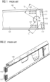
- a rear beam 100 of a nacelle of a wind turbine is shown.
- the rear beam 100 comprises a first layer 101 and a second layer 103.
- the first layer 101 and the second layer 103 are connected by a first connection face 105 that consists of two straight rows of bolts and a second connection face 107 that consists of two straight rows of bolts as well.
- a force F on a bolt will in general vary linear with a distance r from a centroid of all bolts to a particular bolt.
- F 2 F 1 • r 2 r 1
- rear beam 100 comprises a third connection face 115 and a fourth connection face 117 for connecting with a main foundation. If a downward force is added to the beam 100, all bolts in connection face 115 will be loaded by a horizontal force going to the left and all bolts in connection face 117 will be loaded by a horizontal force going to the right. Additionally, on all bolts in connection faces 115 and 117 there will be a vertical force component going upwards.
- Fig. 2 shows the rear beam 100 in a top view. From this view, it can be understood that, by separating the connection faces 115 and 117, a load can only be transferred from the third connection face 115 to the fourth connections face 117 by shear forces in a domain between connection faces 115 and 117.
- Fig. 3 shows a support structure 300 according to an embodiment.
- the support structure 300 comprises a first rear beam 301 a second rear beam 303 and a main foundation 305.
- the first rear beam 301 and the main foundation 305 are connected by a first connection arrangement 307 in a first connection area 309.
- the second rear beam 303 and the main foundation 305 are connected by a second connection arrangement 311 in a second connection area 313.
- Fig. 4 the support structure 300 is shown in a side view.
- the main foundation 305 is shown in detail with an installation guide 315 for installation of the connection arrangement 311.
- connection arrangement 311 can be provided very fast and precise by a technician.
- the installation guide 315 may be part of the main foundation 305.
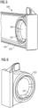
- a rear beam 500 is shown.
- the rear beam 500 comprises a first layer 501, a second layer 503, and a connection area 505.
- an installation guide 507 is located, in which bolts are inserted with a distance to each other that is predetermined by the installation guide 507.
- connection area 505 is shown in more detail.
- the installation guide 507 is an elevated structure comprising bore holes for receiving bolts.
- the bore holes are arranged in a circular shape, such that each bore hole and a corresponding connection element inserted in the bore hole has the same distance to a center of an opening of the connection area 505.
- the bore holes may be arranged in any other at least partially curved shape.
- Fig. 7 the rear beam 500 is shown on a cut view.
- the rear beam 500 has a sandwich structure comprising the first layer 501, a reinforcement element 509, and the second layer 503, which are connected by bolts of a connection arrangement 511 that are inserted in the installation guide 507 as shown in Fig. 5 .
- the first layer 501 and the second layer 503 are J-shaped.
- the J-shaped structure of the first layer 501 and the second layer 503 enables a transfer of loads between horizontal areas and vertical areas of the rear beam 500.
- the different cross sections of the upper and lower flanges provide for a very high capability for carrying buckling loads, which improves strength and stiffness of the rear beam 500 with a minimal amount of material.
- Fig. 8 the reinforcement element 509 is shown in detail.
- the reinforcement element 509 transfers bolt pretensions from the first layer 501 to the second layer 503 and vice versa.
- the reinforcement element 509 reinforces the rear beam in the connection area 505.
- the reinforcement element 509 may be part of a main foundation.
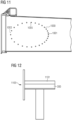
- connection arrangement 800 is shown.
- the connection arrangement 800 is built by an oval shaped weld placed in a connection area 801 on a first layer 803 and may be used to connect the first layer 803 with a main foundation 805.
- connection arrangement 900 is shown.
- the connection arrangement 900 is built by an oval shaped welding section placed in the connection area 801 on the first layer 803 and may be used to connect the first layer 803 with the main foundation 805 as shown in Fig 9 .
- connection arrangement 1000 comprises a first section 1001, where connection elements 1005, such as bolts, forming the connection arrangement 1000 are arranged close to each other, i.e. arranged with a small distance between each other, to transfer a high load on a high number of bolts.
- connection arrangement 1000 comprises a second section 1003, where bolts forming the connection arrangement 1000 are arranged in greater distance to each other than in the first section 1001. Since in the second section 1003 the loads are smaller than in the first section 1001, the number of bolts is reduced and the amount of material together with the weight of a corresponding support structure is minimized.
- a wind turbine 1100 is shown.
- the wind turbine 1100 comprises a nacelle 1101 that comprises the support structure 300 as described with respect to Fig. 3 .
- a method 1200 comprising an alignment step 1201 for aligning rear end beams with a main foundation in a connection area, and a connection step 1203 for connecting each the rear end beams with the main foundation in the connection area by a single connection arrangement.
Landscapes
- Engineering & Computer Science (AREA)
- Life Sciences & Earth Sciences (AREA)
- Sustainable Development (AREA)
- Sustainable Energy (AREA)
- Chemical & Material Sciences (AREA)
- Combustion & Propulsion (AREA)
- Mechanical Engineering (AREA)
- General Engineering & Computer Science (AREA)
- Wind Motors (AREA)
Claims (10)
- Structure de support (300) pour une nacelle (1101) d'une éolienne (1100), dans laquelle la structure de support (300) comprend une fondation principale (305, 805) et un cadre arrière comprenant seulement deux poutres d'extrémité arrière (301, 303, 500) qui sont raccordées à la fondation principale (305, 805) à une extrémité et s'étendent depuis la fondation principale (305, 805), dans laquelle la fondation principale (305, 805) et chacune des seulement deux poutres d'extrémité arrière (301, 303, 500) sont raccordées dans une zone de raccordement (309, 313, 801) par un seul dispositif de raccordement (307, 311, 511, 800, 900, 1000),
dans laquelle le dispositif de raccordement (307, 311, 511, 800, 900, 1000) comprend au moins une section incurvée avec un motif incurvé d'éléments de raccordement (1005), de telle sorte qu'une charge sur la zone de raccordement (309, 313, 801) est répartie au sein du dispositif de raccordement (307, 311, 511, 800, 900, 1000). - Structure de support (300) selon la revendication 1, dans laquelle les éléments de raccordement (1005) sont choisis parmi les boulons, les soudures, les broches cylindriques, les rivets ou une combinaison de ceux-ci.
- Structure de support (300) selon la revendication 1 ou 2, dans laquelle des éléments de raccordement (1005) dans une première section (1001) de l'agencement de raccordement (307, 311, 511, 800, 900, 1000) sont situés plus près les uns des autres que des éléments de raccordement (1005) dans une deuxième section (1003) de l'agencement de raccordement (307, 311, 511, 800, 900, 1000).
- Structure de support (300) selon l'une quelconque des revendications précédentes, dans laquelle l'agencement de raccordement (307, 311, 511, 800, 900, 1000) a une forme qui est au moins partiellement ovale ou circulaire.
- Structure de support (300) selon l'une quelconque des revendications précédentes, dans laquelle l'agencement de raccordement (307, 311, 511, 800, 900, 1000) s'étend dans un sens longitudinal du cadre arrière.
- Structure de support (300) selon l'une quelconque des revendications précédentes, dans laquelle chacune des poutres d'extrémité arrière (301, 303, 500) comprend une ou plusieurs couches en forme de J (501, 503).
- Structure de support (300) selon la revendication 6, dans laquelle dans le cas où chacune des poutres d'extrémité arrière (301, 303, 500) comprend au moins deux couches en forme de J (501, 503), des brides qui doivent être chargées par des charges de compression des au moins deux couches en forme de J (501, 503), au moins partiellement, ont des zones en section transversale plus grandes que des brides des au moins deux couches en forme de J (501, 503) qui doivent être chargées par des charges de tension.
- Structure de support (300) selon la revendication 7, dans laquelle dans la zone de raccordement (309, 313, 801) est agencé au moins un élément de renforcement qui recouvre au moins une section de la zone de raccordement (309, 313, 801).
- Éolienne (1100) avec une structure de support (300) selon l'une quelconque des revendications 1 à 8.
- Procédé (1200) de raccordement d'un cadre arrière à une fondation principale (305, 805) dans une structure de support (300) selon l'une quelconque des revendications 1 à 8, dans lequel le cadre arrière comprend uniquement deux poutres d'extrémité arrière (301, 303, 500), le procédé comprenant les étapes de :- alignement (1201) de chacune des poutres d'extrémité arrière (301, 303, 500) avec la fondation principale (305, 805) dans une zone de raccordement (309, 313, 801),- raccordement (1203) de chacune des poutres d'extrémité arrière (301, 303, 500) à la fondation principale (305, 805) dans la zone de raccordement (309, 313, 801) par un seul agencement de raccordement (307, 311, 511, 800, 900, 1000),dans lequel l'agencement de raccordement (307, 311, 511, 800, 900, 1000) comprend au moins une section incurvée avec un motif incurvé d'éléments de raccordement (1005), de telle sorte qu'une charge sur la zone de raccordement est répartie au sein du dispositif de raccordement (307, 311, 511, 800, 900, 1000).
Applications Claiming Priority (2)
| Application Number | Priority Date | Filing Date | Title |
|---|---|---|---|
| EP19195917.0A EP3789610A1 (fr) | 2019-09-06 | 2019-09-06 | Structure de support pour une nacelle d'une éolienne |
| PCT/EP2020/072224 WO2021043530A1 (fr) | 2019-09-06 | 2020-08-07 | Structure de soutien pour nacelle d'éolienne |
Publications (2)
| Publication Number | Publication Date |
|---|---|
| EP4004366A1 EP4004366A1 (fr) | 2022-06-01 |
| EP4004366B1 true EP4004366B1 (fr) | 2024-12-04 |
Family
ID=67875342
Family Applications (2)
| Application Number | Title | Priority Date | Filing Date |
|---|---|---|---|
| EP19195917.0A Withdrawn EP3789610A1 (fr) | 2019-09-06 | 2019-09-06 | Structure de support pour une nacelle d'une éolienne |
| EP20763990.7A Active EP4004366B1 (fr) | 2019-09-06 | 2020-08-07 | Structure de support pour une nacelle d'une éolienne |
Family Applications Before (1)
| Application Number | Title | Priority Date | Filing Date |
|---|---|---|---|
| EP19195917.0A Withdrawn EP3789610A1 (fr) | 2019-09-06 | 2019-09-06 | Structure de support pour une nacelle d'une éolienne |
Country Status (4)
| Country | Link |
|---|---|
| EP (2) | EP3789610A1 (fr) |
| DK (1) | DK4004366T3 (fr) |
| ES (1) | ES3011339T3 (fr) |
| WO (1) | WO2021043530A1 (fr) |
Families Citing this family (1)
| Publication number | Priority date | Publication date | Assignee | Title |
|---|---|---|---|---|
| EP4155537A1 (fr) * | 2021-09-27 | 2023-03-29 | Siemens Gamesa Renewable Energy A/S | Ensemble support de turbine éolienne et éolienne |
Family Cites Families (5)
| Publication number | Priority date | Publication date | Assignee | Title |
|---|---|---|---|---|
| WO2007096008A1 (fr) * | 2006-02-27 | 2007-08-30 | Ecotecnia Energias Renovables, S.L. | Procede et systeme pour lever des pieces lourdes vers une turbine a vent |
| KR101234380B1 (ko) * | 2008-06-11 | 2013-02-18 | 미츠비시 쥬고교 가부시키가이샤 | 구조 부재용의 플랜지 이음매 |
| EP2494198B1 (fr) | 2009-10-27 | 2015-03-18 | Vestas Wind Systems A/S | Éolienne |
| DE102011007836B3 (de) * | 2011-04-21 | 2012-10-04 | Repower Systems Se | Maschinenträger einer Windenergieanlage mit Verkabelung und Verfahren zum Verlegen eines Kabelstrangs an einem Maschinenträger einer Windenergieanlage |
| WO2019038709A1 (fr) * | 2017-08-24 | 2019-02-28 | Suzlon Energy Ltd. | Structure de cadre pour une éolienne et procédé de fabrication d'une structure de cadre |
-
2019
- 2019-09-06 EP EP19195917.0A patent/EP3789610A1/fr not_active Withdrawn
-
2020
- 2020-08-07 EP EP20763990.7A patent/EP4004366B1/fr active Active
- 2020-08-07 DK DK20763990.7T patent/DK4004366T3/da active
- 2020-08-07 WO PCT/EP2020/072224 patent/WO2021043530A1/fr not_active Ceased
- 2020-08-07 ES ES20763990T patent/ES3011339T3/es active Active
Also Published As
| Publication number | Publication date |
|---|---|
| DK4004366T3 (en) | 2025-02-03 |
| ES3011339T3 (en) | 2025-04-07 |
| WO2021043530A1 (fr) | 2021-03-11 |
| EP4004366A1 (fr) | 2022-06-01 |
| EP3789610A1 (fr) | 2021-03-10 |
Similar Documents
| Publication | Publication Date | Title |
|---|---|---|
| EP1889987B1 (fr) | Structures de support sans bride | |
| EP2558716B1 (fr) | Calage du pale d'une eolienne ayant boulon pour rainure en t | |
| EP2155470B1 (fr) | Procédé de production d'un revêtement composite dans le domaine aéronautique et astronautique | |
| US7954419B2 (en) | Belly system for a vehicle | |
| EP2319648A1 (fr) | Joint à bride destiné à un élément de charpente | |
| JP2010077965A (ja) | フランジレス風力発電タワーのための設計 | |
| WO2001046582A2 (fr) | Pale de rotor destinee a des installations d'energie eolienne | |
| US20230175248A1 (en) | Structural fuses configured to yield in tension and compression and structures including the same | |
| EP3653490B1 (fr) | Ensemble de cadre pour une section arrière d'un aéronef et section arrière d'un aéronef comprenant ledit ensemble de cadre | |
| AU2021203745B2 (en) | Dipper handle assembly for a power shovel | |
| EP2534376B1 (fr) | Partie de la paroi d'une tour de turbine éolienne | |
| EP3789610A1 (fr) | Structure de support pour une nacelle d'une éolienne | |
| US12480467B2 (en) | Root section, wind turbine blade and methods for producing and modifying a root portion of a wind turbine blade | |
| US7293643B2 (en) | Plate link chain having inner and outer plate members | |
| US20130333995A1 (en) | Structural part having the ability to dissipate energy | |
| EP4136347B1 (fr) | Alternance de calage pour brides de structure de support | |
| EP2402605B1 (fr) | Tour d'éolienne | |
| JP3998236B2 (ja) | コンクリート部材 | |
| AU784892B2 (en) | A composite beam | |
| RU2716987C1 (ru) | Шпренгель фермы дождевальной машины | |
| RU2651717C1 (ru) | Заполненный бетоном трубчатый элемент фермы и ферменная конструкция | |
| JP5612455B2 (ja) | 乗客コンベア | |
| EP3447283B1 (fr) | Nacelle d'éolienne et support de générateur | |
| US9085867B2 (en) | Water-gate | |
| EP4065835A1 (fr) | Pale d'éolienne modulaire |
Legal Events
| Date | Code | Title | Description |
|---|---|---|---|
| STAA | Information on the status of an ep patent application or granted ep patent |
Free format text: STATUS: UNKNOWN |
|
| STAA | Information on the status of an ep patent application or granted ep patent |
Free format text: STATUS: THE INTERNATIONAL PUBLICATION HAS BEEN MADE |
|
| PUAI | Public reference made under article 153(3) epc to a published international application that has entered the european phase |
Free format text: ORIGINAL CODE: 0009012 |
|
| STAA | Information on the status of an ep patent application or granted ep patent |
Free format text: STATUS: REQUEST FOR EXAMINATION WAS MADE |
|
| 17P | Request for examination filed |
Effective date: 20220224 |
|
| AK | Designated contracting states |
Kind code of ref document: A1 Designated state(s): AL AT BE BG CH CY CZ DE DK EE ES FI FR GB GR HR HU IE IS IT LI LT LU LV MC MK MT NL NO PL PT RO RS SE SI SK SM TR |
|
| DAV | Request for validation of the european patent (deleted) | ||
| DAX | Request for extension of the european patent (deleted) | ||
| GRAP | Despatch of communication of intention to grant a patent |
Free format text: ORIGINAL CODE: EPIDOSNIGR1 |
|
| STAA | Information on the status of an ep patent application or granted ep patent |
Free format text: STATUS: GRANT OF PATENT IS INTENDED |
|
| INTG | Intention to grant announced |
Effective date: 20240528 |
|
| GRAS | Grant fee paid |
Free format text: ORIGINAL CODE: EPIDOSNIGR3 |
|
| GRAA | (expected) grant |
Free format text: ORIGINAL CODE: 0009210 |
|
| STAA | Information on the status of an ep patent application or granted ep patent |
Free format text: STATUS: THE PATENT HAS BEEN GRANTED |
|
| AK | Designated contracting states |
Kind code of ref document: B1 Designated state(s): AL AT BE BG CH CY CZ DE DK EE ES FI FR GB GR HR HU IE IS IT LI LT LU LV MC MK MT NL NO PL PT RO RS SE SI SK SM TR |
|
| REG | Reference to a national code |
Ref country code: CH Ref legal event code: EP |
|
| REG | Reference to a national code |
Ref country code: DE Ref legal event code: R096 Ref document number: 602020042544 Country of ref document: DE |
|
| REG | Reference to a national code |
Ref country code: IE Ref legal event code: FG4D |
|
| REG | Reference to a national code |
Ref country code: DK Ref legal event code: T3 Effective date: 20250127 |
|
| REG | Reference to a national code |
Ref country code: LT Ref legal event code: MG9D |
|
| REG | Reference to a national code |
Ref country code: ES Ref legal event code: FG2A Ref document number: 3011339 Country of ref document: ES Kind code of ref document: T3 Effective date: 20250407 |
|
| REG | Reference to a national code |
Ref country code: NL Ref legal event code: MP Effective date: 20241204 |
|
| PG25 | Lapsed in a contracting state [announced via postgrant information from national office to epo] |
Ref country code: HR Free format text: LAPSE BECAUSE OF FAILURE TO SUBMIT A TRANSLATION OF THE DESCRIPTION OR TO PAY THE FEE WITHIN THE PRESCRIBED TIME-LIMIT Effective date: 20241204 |
|
| PG25 | Lapsed in a contracting state [announced via postgrant information from national office to epo] |
Ref country code: FI Free format text: LAPSE BECAUSE OF FAILURE TO SUBMIT A TRANSLATION OF THE DESCRIPTION OR TO PAY THE FEE WITHIN THE PRESCRIBED TIME-LIMIT Effective date: 20241204 |
|
| PG25 | Lapsed in a contracting state [announced via postgrant information from national office to epo] |
Ref country code: BG Free format text: LAPSE BECAUSE OF FAILURE TO SUBMIT A TRANSLATION OF THE DESCRIPTION OR TO PAY THE FEE WITHIN THE PRESCRIBED TIME-LIMIT Effective date: 20241204 |
|
| PG25 | Lapsed in a contracting state [announced via postgrant information from national office to epo] |
Ref country code: NO Free format text: LAPSE BECAUSE OF FAILURE TO SUBMIT A TRANSLATION OF THE DESCRIPTION OR TO PAY THE FEE WITHIN THE PRESCRIBED TIME-LIMIT Effective date: 20250304 |
|
| PG25 | Lapsed in a contracting state [announced via postgrant information from national office to epo] |
Ref country code: LV Free format text: LAPSE BECAUSE OF FAILURE TO SUBMIT A TRANSLATION OF THE DESCRIPTION OR TO PAY THE FEE WITHIN THE PRESCRIBED TIME-LIMIT Effective date: 20241204 Ref country code: GR Free format text: LAPSE BECAUSE OF FAILURE TO SUBMIT A TRANSLATION OF THE DESCRIPTION OR TO PAY THE FEE WITHIN THE PRESCRIBED TIME-LIMIT Effective date: 20250305 |
|
| PG25 | Lapsed in a contracting state [announced via postgrant information from national office to epo] |
Ref country code: RS Free format text: LAPSE BECAUSE OF FAILURE TO SUBMIT A TRANSLATION OF THE DESCRIPTION OR TO PAY THE FEE WITHIN THE PRESCRIBED TIME-LIMIT Effective date: 20250304 |
|
| PG25 | Lapsed in a contracting state [announced via postgrant information from national office to epo] |
Ref country code: NL Free format text: LAPSE BECAUSE OF FAILURE TO SUBMIT A TRANSLATION OF THE DESCRIPTION OR TO PAY THE FEE WITHIN THE PRESCRIBED TIME-LIMIT Effective date: 20241204 |
|
| REG | Reference to a national code |
Ref country code: AT Ref legal event code: MK05 Ref document number: 1748411 Country of ref document: AT Kind code of ref document: T Effective date: 20241204 |
|
| PG25 | Lapsed in a contracting state [announced via postgrant information from national office to epo] |
Ref country code: SM Free format text: LAPSE BECAUSE OF FAILURE TO SUBMIT A TRANSLATION OF THE DESCRIPTION OR TO PAY THE FEE WITHIN THE PRESCRIBED TIME-LIMIT Effective date: 20241204 |
|
| PG25 | Lapsed in a contracting state [announced via postgrant information from national office to epo] |
Ref country code: PL Free format text: LAPSE BECAUSE OF FAILURE TO SUBMIT A TRANSLATION OF THE DESCRIPTION OR TO PAY THE FEE WITHIN THE PRESCRIBED TIME-LIMIT Effective date: 20241204 |
|
| PG25 | Lapsed in a contracting state [announced via postgrant information from national office to epo] |
Ref country code: IS Free format text: LAPSE BECAUSE OF FAILURE TO SUBMIT A TRANSLATION OF THE DESCRIPTION OR TO PAY THE FEE WITHIN THE PRESCRIBED TIME-LIMIT Effective date: 20250404 |
|
| PG25 | Lapsed in a contracting state [announced via postgrant information from national office to epo] |
Ref country code: PT Free format text: LAPSE BECAUSE OF FAILURE TO SUBMIT A TRANSLATION OF THE DESCRIPTION OR TO PAY THE FEE WITHIN THE PRESCRIBED TIME-LIMIT Effective date: 20250404 |
|
| PG25 | Lapsed in a contracting state [announced via postgrant information from national office to epo] |
Ref country code: EE Free format text: LAPSE BECAUSE OF FAILURE TO SUBMIT A TRANSLATION OF THE DESCRIPTION OR TO PAY THE FEE WITHIN THE PRESCRIBED TIME-LIMIT Effective date: 20241204 |
|
| PG25 | Lapsed in a contracting state [announced via postgrant information from national office to epo] |
Ref country code: AT Free format text: LAPSE BECAUSE OF FAILURE TO SUBMIT A TRANSLATION OF THE DESCRIPTION OR TO PAY THE FEE WITHIN THE PRESCRIBED TIME-LIMIT Effective date: 20241204 Ref country code: RO Free format text: LAPSE BECAUSE OF FAILURE TO SUBMIT A TRANSLATION OF THE DESCRIPTION OR TO PAY THE FEE WITHIN THE PRESCRIBED TIME-LIMIT Effective date: 20241204 |
|
| PG25 | Lapsed in a contracting state [announced via postgrant information from national office to epo] |
Ref country code: SK Free format text: LAPSE BECAUSE OF FAILURE TO SUBMIT A TRANSLATION OF THE DESCRIPTION OR TO PAY THE FEE WITHIN THE PRESCRIBED TIME-LIMIT Effective date: 20241204 |
|
| PG25 | Lapsed in a contracting state [announced via postgrant information from national office to epo] |
Ref country code: CZ Free format text: LAPSE BECAUSE OF FAILURE TO SUBMIT A TRANSLATION OF THE DESCRIPTION OR TO PAY THE FEE WITHIN THE PRESCRIBED TIME-LIMIT Effective date: 20241204 |
|
| PG25 | Lapsed in a contracting state [announced via postgrant information from national office to epo] |
Ref country code: IT Free format text: LAPSE BECAUSE OF FAILURE TO SUBMIT A TRANSLATION OF THE DESCRIPTION OR TO PAY THE FEE WITHIN THE PRESCRIBED TIME-LIMIT Effective date: 20241204 |
|
| REG | Reference to a national code |
Ref country code: DE Ref legal event code: R097 Ref document number: 602020042544 Country of ref document: DE |
|
| PG25 | Lapsed in a contracting state [announced via postgrant information from national office to epo] |
Ref country code: SE Free format text: LAPSE BECAUSE OF FAILURE TO SUBMIT A TRANSLATION OF THE DESCRIPTION OR TO PAY THE FEE WITHIN THE PRESCRIBED TIME-LIMIT Effective date: 20241204 |
|
| PGFP | Annual fee paid to national office [announced via postgrant information from national office to epo] |
Ref country code: ES Payment date: 20250916 Year of fee payment: 6 |
|
| PGFP | Annual fee paid to national office [announced via postgrant information from national office to epo] |
Ref country code: DE Payment date: 20250827 Year of fee payment: 6 Ref country code: DK Payment date: 20250825 Year of fee payment: 6 |
|
| PLBE | No opposition filed within time limit |
Free format text: ORIGINAL CODE: 0009261 |
|
| STAA | Information on the status of an ep patent application or granted ep patent |
Free format text: STATUS: NO OPPOSITION FILED WITHIN TIME LIMIT |
|
| REG | Reference to a national code |
Ref country code: CH Ref legal event code: L10 Free format text: ST27 STATUS EVENT CODE: U-0-0-L10-L00 (AS PROVIDED BY THE NATIONAL OFFICE) Effective date: 20251015 |
|
| PGFP | Annual fee paid to national office [announced via postgrant information from national office to epo] |
Ref country code: GB Payment date: 20250826 Year of fee payment: 6 |
|
| PGFP | Annual fee paid to national office [announced via postgrant information from national office to epo] |
Ref country code: FR Payment date: 20250825 Year of fee payment: 6 |
|
| 26N | No opposition filed |
Effective date: 20250905 |
|
| REG | Reference to a national code |
Ref country code: CH Ref legal event code: H13 Free format text: ST27 STATUS EVENT CODE: U-0-0-H10-H13 (AS PROVIDED BY THE NATIONAL OFFICE) Effective date: 20260324 |
|
| PG25 | Lapsed in a contracting state [announced via postgrant information from national office to epo] |
Ref country code: MC Free format text: LAPSE BECAUSE OF FAILURE TO SUBMIT A TRANSLATION OF THE DESCRIPTION OR TO PAY THE FEE WITHIN THE PRESCRIBED TIME-LIMIT Effective date: 20241204 |
|
| PG25 | Lapsed in a contracting state [announced via postgrant information from national office to epo] |
Ref country code: LU Free format text: LAPSE BECAUSE OF NON-PAYMENT OF DUE FEES Effective date: 20250807 |
|
| PG25 | Lapsed in a contracting state [announced via postgrant information from national office to epo] |
Ref country code: CH Free format text: LAPSE BECAUSE OF NON-PAYMENT OF DUE FEES Effective date: 20250831 |