EP4004331B1 - Drill head and method for producing a vertical borehole in the ground - Google Patents
Drill head and method for producing a vertical borehole in the ground Download PDFInfo
- Publication number
- EP4004331B1 EP4004331B1 EP20746138.5A EP20746138A EP4004331B1 EP 4004331 B1 EP4004331 B1 EP 4004331B1 EP 20746138 A EP20746138 A EP 20746138A EP 4004331 B1 EP4004331 B1 EP 4004331B1
- Authority
- EP
- European Patent Office
- Prior art keywords
- drill head
- opening
- ground
- suction box
- loosened
- Prior art date
- Legal status (The legal status is an assumption and is not a legal conclusion. Google has not performed a legal analysis and makes no representation as to the accuracy of the status listed.)
- Active
Links
- 238000004519 manufacturing process Methods 0.000 title claims description 3
- 238000005553 drilling Methods 0.000 claims description 43
- 239000002609 medium Substances 0.000 claims description 29
- 230000001133 acceleration Effects 0.000 claims description 20
- 239000006163 transport media Substances 0.000 claims description 19
- 239000007788 liquid Substances 0.000 claims description 10
- 238000000034 method Methods 0.000 claims description 9
- 238000007599 discharging Methods 0.000 claims 2
- 238000010926 purge Methods 0.000 claims 1
- 239000002689 soil Substances 0.000 description 64
- 239000000463 material Substances 0.000 description 14
- 239000011435 rock Substances 0.000 description 12
- 238000011010 flushing procedure Methods 0.000 description 7
- 238000005520 cutting process Methods 0.000 description 6
- XLYOFNOQVPJJNP-UHFFFAOYSA-N water Substances O XLYOFNOQVPJJNP-UHFFFAOYSA-N 0.000 description 5
- 229910000278 bentonite Inorganic materials 0.000 description 4
- 239000000440 bentonite Substances 0.000 description 4
- SVPXDRXYRYOSEX-UHFFFAOYSA-N bentoquatam Chemical compound O.O=[Si]=O.O=[Al]O[Al]=O SVPXDRXYRYOSEX-UHFFFAOYSA-N 0.000 description 4
- 239000000203 mixture Substances 0.000 description 3
- 239000007787 solid Substances 0.000 description 2
- 239000000725 suspension Substances 0.000 description 2
- 238000010521 absorption reaction Methods 0.000 description 1
- 238000004140 cleaning Methods 0.000 description 1
- 230000007423 decrease Effects 0.000 description 1
- 230000001419 dependent effect Effects 0.000 description 1
- 238000001514 detection method Methods 0.000 description 1
- 239000000428 dust Substances 0.000 description 1
- 230000002262 irrigation Effects 0.000 description 1
- 238000003973 irrigation Methods 0.000 description 1
- 238000005065 mining Methods 0.000 description 1
- 230000008092 positive effect Effects 0.000 description 1
- 238000002360 preparation method Methods 0.000 description 1
- 239000010865 sewage Substances 0.000 description 1
Images


Classifications
-
- E—FIXED CONSTRUCTIONS
- E21—EARTH DRILLING; MINING
- E21B—EARTH DRILLING, e.g. DEEP DRILLING; OBTAINING OIL, GAS, WATER, SOLUBLE OR MELTABLE MATERIALS OR A SLURRY OF MINERALS FROM WELLS
- E21B10/00—Drill bits
- E21B10/60—Drill bits characterised by conduits or nozzles for drilling fluids
- E21B10/602—Drill bits characterised by conduits or nozzles for drilling fluids the bit being a rotary drag type bit with blades
-
- E—FIXED CONSTRUCTIONS
- E21—EARTH DRILLING; MINING
- E21B—EARTH DRILLING, e.g. DEEP DRILLING; OBTAINING OIL, GAS, WATER, SOLUBLE OR MELTABLE MATERIALS OR A SLURRY OF MINERALS FROM WELLS
- E21B21/00—Methods or apparatus for flushing boreholes, e.g. by use of exhaust air from motor
- E21B21/12—Methods or apparatus for flushing boreholes, e.g. by use of exhaust air from motor using drilling pipes with plural fluid passages, e.g. closed circulation systems
-
- E—FIXED CONSTRUCTIONS
- E21—EARTH DRILLING; MINING
- E21B—EARTH DRILLING, e.g. DEEP DRILLING; OBTAINING OIL, GAS, WATER, SOLUBLE OR MELTABLE MATERIALS OR A SLURRY OF MINERALS FROM WELLS
- E21B10/00—Drill bits
- E21B10/42—Rotary drag type drill bits with teeth, blades or like cutting elements, e.g. fork-type bits, fish tail bits
-
- E—FIXED CONSTRUCTIONS
- E21—EARTH DRILLING; MINING
- E21D—SHAFTS; TUNNELS; GALLERIES; LARGE UNDERGROUND CHAMBERS
- E21D9/00—Tunnels or galleries, with or without linings; Methods or apparatus for making thereof; Layout of tunnels or galleries
- E21D9/10—Making by using boring or cutting machines
- E21D9/1006—Making by using boring or cutting machines with rotary cutting tools
-
- E—FIXED CONSTRUCTIONS
- E21—EARTH DRILLING; MINING
- E21D—SHAFTS; TUNNELS; GALLERIES; LARGE UNDERGROUND CHAMBERS
- E21D9/00—Tunnels or galleries, with or without linings; Methods or apparatus for making thereof; Layout of tunnels or galleries
- E21D9/10—Making by using boring or cutting machines
- E21D9/11—Making by using boring or cutting machines with a rotary drilling-head cutting simultaneously the whole cross-section, i.e. full-face machines
-
- E—FIXED CONSTRUCTIONS
- E21—EARTH DRILLING; MINING
- E21D—SHAFTS; TUNNELS; GALLERIES; LARGE UNDERGROUND CHAMBERS
- E21D1/00—Sinking shafts
- E21D1/03—Sinking shafts mechanically, e.g. by loading shovels or loading buckets, scraping devices, conveying screws
- E21D1/06—Sinking shafts mechanically, e.g. by loading shovels or loading buckets, scraping devices, conveying screws with shaft-boring cutters
Description
Die Erfindung betrifft einen Bohrkopf und ein Verfahren zum Erstellen einer im Wesentlichen vertikalen Bohrung im Boden, insbesondere zum Erstellen eines Schachts, mit einem Körper, der mit einem Rotationsantrieb einer Bohrvorrichtung verbindbar ist, mit an dem Körper angeordneten Bohrwerkzeugen zum Lösen des Bodens an einer Ortsbrust der Bohrung, mit einer Abfördervorrichtung zum Abtransport des gelösten Bodens an der Ortsbrust, die mit einer Ansaugeinheit zum Ansaugen eines Fördermediums über eine Förderleitung verbindbar ist, wobei die Abfördervorrichtung einen am Körper angeordneten Öffnungsbereich mit wenigstens einer Öffnung im Bereich der Bohrwerkzeuge an der Ortsbrust aufweist, wobei die wenigstens eine Öffnung des Öffnungsbereichs mit einem Saugkasten als Bestandteil der Abfördervorrichtung verbunden ist, der an einem der Öffnung gegenüberliegenden Ende eine Anschlussöffnung für eine Verbindung mit der Förderleitung aufweist, und wobei wenigstens ein Element vorgesehen ist, das auf den gelösten Boden im Bereich Saugkastens eine Beschleunigung ausübt, durch die der von den Bohrwerkzeugen gelöste Boden in den Öffnungsbereich und/oder durch die Öffnung in den Saugkasten bewegbar ist, wobei der gelöste Boden im Öffnungsbereich, bevorzugt in der Öffnung und/oder im Saugkasten von dem Fördermedium erfasst und durch die Ansaugeinheit über die Förderleitung abförderbar ist..The invention relates to a drill head and a method for creating a substantially vertical bore in the ground, in particular for creating a shaft, with a body that can be connected to a rotation drive of a drilling device, with drilling tools arranged on the body for loosening the soil at a face the bore, with a discharge device for removing the loosened soil on the face, which can be connected to a suction unit for sucking in a conveyed medium via a conveyor line, the discharge device having an opening area arranged on the body with at least one opening in the area of the drilling tools on the face, wherein the at least one opening of the opening area is connected to a suction box as part of the discharge device, which has a connection opening at an end opposite the opening for a connection to the delivery line, and at least one element is provided which is applied to the loosened soil in the area of the suction box exerts an acceleration through which the soil loosened by the drilling tools can be moved into the opening area and/or through the opening into the suction box, the loosened soil being captured by the conveying medium in the opening area, preferably in the opening and/or in the suction box, and through the Suction unit can be removed via the delivery line.
Ein solcher Bohrkopf ist beispielsweise aus
Aufgabe der Erfindung ist es, die Absaugung bei den zuvor genannten Bohrköpfen zu vereinfachen und gleichzeitig in ihrer Leistungsfähigkeit zu verbessern.The object of the invention is to simplify the suction in the aforementioned drill heads and at the same time to improve their performance.
Gelöst wird die Aufgabe hinsichtlich des Bohrkopfes dadurch, dass der Abstand des Öffnungsbereichs zur Ortsbrust verstellbar ist. Dabei ist vorteilhaft, dass das Verstellen des Abstands über ein vertikales Bewegen des Saugkastens und/oder über ein Verschwenken des Saugkastens um einen Drehpunkt erfolgt, wobei für das Bewegen oder für das Verschwenken ein Antrieb, bevorzugt ein Hydraulikzylinder oder ein Federmechanismus, vorgesehen ist.The task with regard to the drill head is solved in that the distance of the opening area to the face is adjustable. It is advantageous that the distance is adjusted by moving the suction box vertically and/or by pivoting the suction box about a pivot point, with a drive, preferably a hydraulic cylinder or a spring mechanism, being provided for the movement or pivoting.
Hierdurch wird es auf überraschend einfache Weise möglich, den gelösten Boden insbesondere bei schwereren trägen Bestandteilen, die nicht ohne weiteres ansaugbar sind, abzufördern und gleichzeitig die Absaugleistung deutlich zu erhöhen. Weiterhin wird direkt auf einfache Weise die Menge des abgesaugten Materials beeinflussbarThis makes it possible in a surprisingly simple manner to remove the loosened soil, especially in the case of heavier, inert components that cannot be easily sucked in, and at the same time to significantly increase the suction performance. Furthermore, the amount of material extracted can be directly influenced in a simple manner
Eine weitere Lehre der Erfindung sieht vor, es sich bei dem wenigstens einen Element um wenigstens eine Düse handelt, die in den Öffnungsbereich gerichtet vorgesehen ist, die wenigstens einen Strahl eines Transportmediums zum Bewirken der Beschleunigung abgibt.A further teaching of the invention provides that the at least one element is at least one nozzle, which is provided directed into the opening area and which emits at least one jet of a transport medium to bring about the acceleration.
Eine weitere Lehre der Erfindung sieht vor, dass hinter der Öffnung wenigstens ein Umlenkbereich, bevorzugt vor dem Eintritt in den Saugkasten, vorgesehen ist, in dem die Strömungsrichtung des gelösten Bodens umlenkbar ist. Hierdurch lässt sich das abzufördernde Material besonders einfach der Abförderung zuführen und anschließend abfördern.A further teaching of the invention provides that at least one deflection area is provided behind the opening, preferably before entering the suction box, in which the flow direction of the loosened soil can be diverted. This makes it particularly easy for the material to be conveyed to be conveyed to the conveyor and then conveyed away.
Eine weitere Lehre der Erfindung sieht vor, im Öffnungsbereich wenigstens ein Werkzeug zum Lösen des Bodens, bevorzugt in Form einer Zahnleiste, und/oder zum Aufnehmen von gelöstem Boden vorgesehen ist. Hierdurch kann ein Lösen/Aufnehmen von Gestein/Boden an der Ortsbrust direkt im Öffnungsbereich vorgenommen werden. Das so gelöste/aufgenommene Material lässt sich besonders gut der Absaugung zuführen.A further teaching of the invention provides that at least one tool for loosening the soil, preferably in the form of a toothed strip, and/or for picking up loosened soil is provided in the opening area. This means that rock/soil can be loosened/picked up at the face directly in the opening area. The material dissolved/absorbed in this way can be fed particularly well to the suction system.
Weiterhin ist vorteilhaft, dass das wenigstens eine Werkzeug zur Veränderung des Abstands des Werkzeugs zur Ortsbrust bewegbar ist, bevorzugt über wenigstens einen Hydraulikzylinder, und/oder dass das wenigstens eine Werkzeug gegenüber dem Öffnungsbereich verschwenkbar ist, bevorzugt über wenigstens einen Hydraulikzylinder.Furthermore, it is advantageous that the at least one tool can be moved to change the distance of the tool from the face, preferably via at least one hydraulic cylinder, and/or that the at least one tool can be pivoted relative to the opening area, preferably via at least one hydraulic cylinder.
Eine weitere Lehre der Erfindung sieht vor, dass der Öffnungsbereich ein Reinigungswerkzeug, bevorzugt wenigstens ein bewegbares Element und/oder wenigstens eine Düse zum Abgeben eines Mediums, beispielsweise ein Gas (Luft) oder eine Flüssigkeit (Wasser, Bentonitspülung), vorgesehen ist. Hierdurch können Verschlüsse im Öffnungsbereich entweder beseitigt oder verhindert werden.A further teaching of the invention provides that the opening area is provided with a cleaning tool, preferably at least one movable element and/or at least one nozzle for dispensing a medium, for example a gas (air) or a liquid (water, bentonite rinse). This means that closures in the opening area can either be eliminated or prevented.
Eine weitere Lehre der Erfindung sieht vor, dass wenigstens eine Spüldüse vorgesehen ist, mit der von wenigstens einem Bohrwerkzeug gelöster Boden in einen Bereich auf der Ortsbrust transportierbar ist, der von dem Saugkasten beim Bohren mit dem Bohrkopf überfahren wird. Hierdurch wird der Materialtransport zum Saugkasten hin auf einfache Weise verbessert.A further teaching of the invention provides that at least one flushing nozzle is provided, with which soil loosened by at least one drilling tool can be transported into an area on the working face, which is passed over by the suction box when drilling with the drill head. This easily improves the material transport to the suction box.
Eine weitere Lehre der Erfindung sieht vor, dass der Saugkasten wechselbar im Bohrkopf vorgesehen ist. Hierdurch kann der Bohrkopf auf einfache Weise an unterschiedliche geologische Bedingungen angepasst werden. Weiterhin ist auch eine Umkehr der Drehrichtung möglich.A further teaching of the invention provides that the suction box is provided in the drill head in a replaceable manner. This allows the drill head to be easily adapted to different geological conditions. Reversing the direction of rotation is also possible.
Eine weitere Lehre der Erfindung sieht vor, dass ein Klassierungselement im Öffnungsbereich vorgesehen ist. Hierbei kann es sich beispielsweise um ein Gitter, Trennbleche, die den Öffnungsbereich in mehrere Öffnungen aufteilen, oder auch mehrere Öffnungen handeln. Hierdurch wird es auf einfache Weise möglich eine Korngrößenbegrenzung des angesaugten Materials zu erreichen.A further teaching of the invention provides that a classification element is provided in the opening area. This can be, for example, a grid, separating plates that divide the opening area into several openings, or even several openings. This makes it possible to easily limit the grain size of the material sucked in.
Eine weitere Lehre der Erfindung sieht vor, dass der Saugkasten im Wesentlichen horizontal angeordnet ist. Hierdurch werden der Materialtransport im Saugkasten und die Materialaufnahme positiv beeinflusst.A further teaching of the invention provides that the suction box is arranged essentially horizontally. This has a positive effect on material transport in the suction box and material absorption.
Eine weitere Lehre der Erfindung sieht vor, dass sich der Öffnungsbereich vom Mittelpunkt gesehen im Wesentlichen radial nach außen erstreckt. Dabei ist vorteilhaft, dass die Öffnung länglich bzw. schlitzartig ausgeführt ist. Eine weitere Lehre der Erfindung sieht dabei vor, dass sich der lichte Querschnitt der Öffnung entlang des Öffnungsbereichs radial nach außen gesehen verändert, bevorzugt vergrößert. Hierdurch lassen sich die Materialaufnahme, der Ort der Materialaufnahme sowie die Aufnahmemenge auf einfache Weise beeinflussen.A further teaching of the invention provides that the opening area extends essentially radially outwards as viewed from the center. It is advantageous that the opening is elongated or slot-like. A further teaching of the invention provides that the clear cross section of the opening changes along the opening area viewed radially outwards, preferably enlarged. This allows the material intake, the location of the material intake and the intake quantity to be easily influenced.
Weiterhin ist dabei vorteilhaft, dass die Anschlussöffnung des Saugkastens in Bezug auf den Öffnungsbereich gegenüber einer Mittelsenkrechten des Öffnungsbereichs versetzt angeordnet ist, bevorzugt nach außen. Dadurch wird der Saugkasten asymmetrisch aufgebaut. Es lässt sich auf einfache Weise die Ansaugstärke bzw. das Strömungsprofil im Saugkasten oder im Öffnungsbereich beeinflussen, so dass die angesaugte Materialmenge beeinflussbar ist. So kann beispielsweise durch ein Verschieben nach Außen die Strömung im radial gesehen äußeren Bereich des Saugkastens erhöht werden, um die dort anfallende größere Materialmenge besser absaugen zu können.Furthermore, it is advantageous that the connection opening of the suction box is arranged offset in relation to the opening area relative to a median perpendicular of the opening area, preferably towards the outside. This means that the suction box is constructed asymmetrically. The suction strength or the flow profile in the suction box or in the opening area can be easily influenced, so that the amount of material sucked in can be influenced. For example, by moving it outwards, the flow in the radially outer area of the suction box can be increased in order to be able to better suction off the larger amount of material that occurs there.
Eine weitere Lehre der Erfindung sieht vor, dass die Anschlussöffnung des Saugkastens in Bezug auf den Öffnungsbereich gegenüber einer Mittelsenkrechten des Öffnungsbereichs verschwenkt angeordnet ist. Es lässt sich auf einfache Weise die Ansaugstärke bzw. das Strömungsprofil im Saugkasten oder im Öffnungsbereich beeinflussen, so dass die angesaugte Materialmenge beeinflussbar ist. So kann beispielsweise durch ein Verkippen der Anschlussöffnung nach Innen die Strömung im radial gesehen äußeren Bereich des Saugkastens erhöht werden, um die dort anfallende größere Materialmenge besser absaugen zu können.A further teaching of the invention provides that the connection opening of the suction box is arranged pivoted in relation to the opening area relative to a median perpendicular of the opening area. The suction strength or the flow profile in the suction box or in the opening area can be easily influenced, so that the amount of material sucked in can be influenced. For example, by tilting the connection opening inwards, the flow in the radially outer area of the suction box can be increased in order to be able to better suction off the larger amount of material that occurs there.
Eine weitere Lehre der Erfindung sieht vor, dass der Saugkasten im Innenraum wenigstens eine Düse aufweist. Hierdurch kann auf einfache Weise die Bewegung des gelösten Bodens/Gesteins zum Erfassen durch das Fördermedium auf einfache Weise verbessert werden.A further teaching of the invention provides that the suction box has at least one nozzle in the interior. This makes it possible to easily improve the movement of the loosened soil/rock for capture by the conveying medium.
Eine weitere Lehre der Erfindung sieht vor, dass es sich bei dem Fördermedium und/oder bei dem Transportmedium um ein flüssiges oder gasförmiges Medium handelt, bevorzugt Wasser, eine Bentonitsuspension oder Luft. Dabei ist eine besonders bevorzugte Kombination, dass es sich bei dem Fördermedium um Luft und bei dem Transportmedium um Luft oder eine Flüssigkeit, bevorzugt Wasser, handelt. Diese findet Anwendung, wenn der Bohrkopf nicht geflutet ist/sein soll/kann und damit eine flüssigkeitsbasierte Förderung ausscheidet. Es hat sich überraschend gezeigt, dass sich der gelöste Boden/das gelöste Gestein gut durch den abgegebenen Strahl transportierbar/aktivierbar ist und auf vorteilhafte Weise dem Förderstrom aus Luft zuführbar und abförderbar ist.A further teaching of the invention provides that the conveying medium and/or the transport medium is a liquid or gaseous medium, preferably water, a bentonite suspension or air. A particularly preferred combination is that the conveying medium is air and the transport medium is air or a liquid, preferably water. This is used if the drill head is not/should/cannot be flooded and liquid-based production is therefore not possible. It has surprisingly been shown that the dissolved soil/the dissolved rock can be easily transported/activated by the emitted jet and can advantageously be fed into the conveying stream of air and removed.
Eine weitere Lehre der Erfindung sieht vor, dass es sich bei dem wenigstens einen Element um wenigstens ein angetriebenes Rotationselement mit wenigstens einem daran angeordneten Schlagelement handelt, wobei das wenigstens eine Schlagelement durch eine Rotationsbewegung die Beschleunigung des gelösten Bodens über einen Kontakt bewirkt.A further teaching of the invention provides that the at least one element is at least one driven rotating element with at least one impact element arranged thereon, the at least one impact element causing the acceleration of the loosened soil via a contact through a rotational movement.
Vorteilhaft ist dabei, dass das Schlagelement auf einem Schlagkreis, der konzentrisch um das Rotationselement vorgesehen ist, bewegbar ist.It is advantageous that the striking element is movable on a striking circle which is provided concentrically around the rotation element.
Eine weitere Lehre der Erfindung sieht vor, dass das wenigstens eine Schlagelement beweglich an dem wenigstens einen Rotationselement, bevorzugt über ein Gelenk, angeordnet ist.A further teaching of the invention provides that the at least one impact element is movably arranged on the at least one rotation element, preferably via a joint.
Eine weitere Lehre der Erfindung sieht vor, dass es sich bei dem wenigstens einen Schlagelement um einen Hammer, ein Schwert, ein Seil, eine Kette ein Bürstenelement, oder ein Meißel handelt.A further teaching of the invention provides that the at least one striking element is a hammer, a sword, a rope, a chain, a brush element, or a chisel.
Eine weitere Lehre der Erfindung sieht vor, dass die Rotation des wenigstens eine Rotationselements drehzahlregelbar ist.A further teaching of the invention provides that the rotation of the at least one rotation element can be speed-controlled.
Eine weitere Lehre der Erfindung sieht vor, dass das wenigstens eine Schlagelement eine Zerkleinerung des gelösten Bodens bewirkt.A further teaching of the invention provides that the at least one impact element causes the loosened soil to be comminuted.
Eine weitere Lehre der Erfindung sieht vor, dass der Saugkasten horizontal, geneigt und/oder vertikal vorgesehen ist.A further teaching of the invention provides that the suction box is provided horizontally, inclined and/or vertically.
Weiterhin gelöst wird die erfindungsgemäße Aufgabe durch ein Verfahren zum Erstellen einer im Wesentlichen vertikalen Bohrung im Boden, insbesondere zum Erstellen eines Schachts, mit einem Bohrkopf, insbesondere mit einem zuvor beschriebenen Bohrkopf, wobei der Bohrkopf mit einem Rotationsantrieb einer Bohrvorrichtung verbunden wird, wobei der Bohrkopf einen Körper aufweist, an dem Bohrwerkzeuge angeordnet sind, mit denen beim Bohren der Boden an einer Ortsbrust der Bohrung gelöst und auf eine abförderbare Größe zerkleinert wird, wobei der gelöste und zerkleinerte Boden mit einer Abfördervorrichtung von der Ortsbrust abtransportiert wird, die mit einer Ansaugeinheit zum Ansaugen eines Fördermediums über eine Förderleitung verbunden wird, wobei die Abfördervorrichtung einen Saugkasten mit einem Öffnungsbereich mit wenigstens einer Öffnung im Bereich der Bohrwerkzeuge an der Ortsbrust aufweist, mit den Schritten:
- Einbringen einer Beschleunigung in im Bereich des Öffnungsbereichs befindlichen gelösten Boden, und
- Erfassen des gelösten Bodens von einem Fördermedium und Abfördern durch die Ansaugeinheit über die Förderleitung.
- Introducing an acceleration into loosened soil in the area of the opening area, and
- Capturing the loosened soil from a conveying medium and conveying it away through the suction unit via the conveying line.
Eine weitere Lehre der Erfindung sieht vor, dass der gelöste Boden durch die Öffnung in den Saugkasten durch die eingebrachte Beschleunigung bewegt wird.A further teaching of the invention provides that the loosened soil is moved through the opening into the suction box by the acceleration introduced.
Eine weitere Lehre der Erfindung sieht vor, dass das Erfassen im Saugkasten und/oder im Öffnungsbereich, bevorzugt vor der Öffnung, erfolgt.A further teaching of the invention provides that the detection takes place in the suction box and/or in the opening area, preferably in front of the opening.
Eine weitere Lehre der Erfindung sieht vor, dass die Beschleunigung durch Abgabe eines Strahls eines Transportmediums aus einer Düse, die in den Öffnungsbereich des Saugkastens als Bestandteil der Abfördervorrichtung gerichtet ist, erfolgt.A further teaching of the invention provides that the acceleration takes place by emitting a jet of a transport medium from a nozzle which is directed into the opening area of the suction box as part of the discharge device.
Eine weitere Lehre der Erfindung sieht vor, dass das Bewegen des gelösten Bodens durch das Transportmedium erfolgt.A further teaching of the invention provides that the loosened soil is moved through the transport medium.
Alternativ oder ergänzend ist weiterhin vorgesehen, dass die Beschleunigung durch wenigstens ein angetriebenes Rotationselement mit wenigstens einem daran angeordneten Schlagelement erfolgt, wobei das wenigstens eine Schlagelement durch eine Rotationsbewegung die Beschleunigung des gelösten Bodens über einen Kontakt bewirkt.Alternatively or additionally, it is further provided that the acceleration takes place by at least one driven rotating element with at least one impact element arranged thereon, the at least one impact element causing the acceleration of the loosened soil via a contact through a rotational movement.
Eine weitere Lehre der Erfindung sieht vor, dass das Bewegen des gelösten Bodens durch das Schlagelement erfolgt.A further teaching of the invention provides that the loosened soil is moved by the impact element.
Vorteilhaft dabei ist, wie zuvor beschrieben, dass es sich bei dem Fördermedium und/oder bei dem Transportmedium um ein flüssiges oder gasförmiges Medium handelt, bevorzugt Wasser, eine Bentonitsuspension oder LuftIt is advantageous, as described above, that the conveying medium and/or the transport medium is a liquid or gaseous medium, preferably water, a bentonite suspension or air
Die Begriffe Boden und Gestein werden in dieser Anmeldung synonym verwendet. Gleiches gilt für gelöster Boden und Bohrklein.The terms soil and rock are used synonymously in this application. The same applies to loosened soil and cuttings.
Nachfolgend wird die Erfindung anhand von Ausführungsbeispielen in Verbindung mit einer Zeichnung näher erläutert. Dabei zeigen:
Dabei zeigen:
- Figur 1
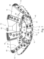
- eine räumliche Ansicht der Unterseite des erfindungsgemäßen Bohrkopfs der ersten Ausführungsform,
- Figur 2
- eine schematische Ausschnittsskizze zu
Figur 1 einer ersten Ausführungsform der Erfindung, - Figur 3
- eine schematische Teilschnittansicht in Draufsicht zu
Figur 2 , Figur 4- eine schematische Darstellung alternativer erfindungsgemäßer Bohrkopfformen,
- Figur 5
- eine schematische räumliche Teilansicht zu
Figur 1 , - Figur 6
- eine weitere schematische räumliche teilweise geschnittene Teilansicht zu
Figur 1 , - Figur 7
- eine weitere schematische räumliche teilweise geschnittene Teilansicht zu
Figur 1 , - Figur 8
- eine erste Prinzipskizze hinsichtlich der erfindungsgemäßen Abförderung in Verbindung mit einem Bohrkopf nach
Figur 1 , - Figur 9
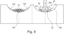
- eine zweite Prinzipskizze hinsichtlich der erfindungsgemäßen Abförderung in Verbindung mit einem Bohrkopf nach
Figur 1 , Figur 10- eine schematische Seitenansicht einer ersten Anordnung einer Saugkasten in einem erfindungsgemäßen Bohrkopf,
Figur 11- eine schematische Seitenansicht einer zweiten Anordnung einer Saugkasten in einem erfindungsgemäßen Bohrkopf,
Figur 12- eine
Teilschnittansicht zu Figur 11 , Figur 13- eine schematische Seitenansicht einer Aufbereitung in einer Bohrvorrichtung mit einem erfindungsgemäßen Bohrkopf,
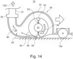
Figur 14- eine Schnittansicht zu einer zweiten Ausführungsform der Erfindung,
Figur 15- eine um 90° gedrehte Schnittansicht zu
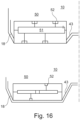
Figur 14 , und Figur 16- alternative
Bohrkopfprofile zu Figur 14 .
Show:
- Figure 1
- a spatial view of the underside of the drill head according to the invention of the first embodiment,
- Figure 2
- a schematic detail sketch
Figure 1 a first embodiment of the invention, - Figure 3
- a schematic partial sectional view in plan view
Figure 2 , - Figure 4
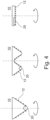
- a schematic representation of alternative drill head shapes according to the invention,
- Figure 5
- a schematic spatial partial view
Figure 1 , - Figure 6
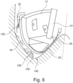
- another schematic spatial partially sectioned partial view
Figure 1 , - Figure 7
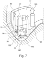
- another schematic spatial partially sectioned partial view
Figure 1 , - Figure 8
- a first schematic sketch with regard to the removal according to the invention in connection with a drill head
Figure 1 , - Figure 9
- a second basic sketch with regard to the removal according to the invention in connection with a drill head
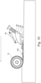
Figure 1 , - Figure 10
- a schematic side view of a first arrangement of a suction box in a drill head according to the invention,
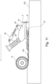
- Figure 11
- a schematic side view of a second arrangement of a suction box in a drill head according to the invention,
- Figure 12
- a partial section view
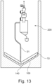
Figure 11 , - Figure 13
- a schematic side view of a preparation in a drilling device with a drill head according to the invention,
- Figure 14
- a sectional view of a second embodiment of the invention,
- Figure 15
- a sectional view rotated by 90°
Figure 14 , and - Figure 16
- alternative drill head profiles
Figure 14 .
Die Unterseite 13 weist einen hier beispielsweise planen (andere Formen sind möglich) Ringabschnitt 15 auf, an den dessen Unterseite 16 Bohrwerkzeuge 12 vorgesehen sind.The
Ausgehend von dem Ringabschnitt erstrecken sich nach außen Arme, hier beispielsweise 8 Arme, 17, die jeweils eine hier beispielsweise plane Flanke 18 aufweisen. An den Flanken können Räumwerkzeuge 19 und Verschleißelemente 40 vorgesehen sein. Alternativ können die Flanken 18 auch vollflächig umlaufend ausgeführt sein.Starting from the ring section, arms extend outwards, here for example 8 arms, 17, each of which has a
Im Zentrum der Unterseite 13 ist hier beispielsweise eine Vertiefung 41 vorgesehen, die beispielsweise eine plane Fläche 42 und Flanken 43 aufweist, an denen ebenfalls Bohrwerkzeuge 12 vorgesehen sind.In the center of the
Die hier beschriebene Bohrkopfform wird auch als W-Bohrkopf bezeichnet. Das Bohrprofil dazu ist in den
Bei den Bohrwerkzeugen 12 kann es sich beispielsweise um Diskenmeißel 12a, Schälmeißel bzw. Schälmesser 12b oder Rollenmeißel 12c oder andere Alternativen handeln. Die Auswahl der Bohrwerkzeuge 12 erfolgt in Abhängigkeit des zu lösenden Bodens/Gesteins zum Erstellen der Bohrung.The
An seiner Oberseite 14 ist in
Weiterhin weist der Körper 11 an seiner Unterseite 13 des W-Bohrkopfes 10 am Ringabschnitt 15 einen Saugkasten 20 auf.Furthermore, the
Alternative Anordnungen des Saugkastens 20 sind in
Der Saugkasten 20 in einer ersten Ausführungsform, wie er beispielsweise in
Der Innenraum 25 wird gebildet durch einen Deckel 26 als Oberseite und einen Boden 27 als Unterseite, die hier als eine Ausführungsform plan ausgeführt sind. Andere Formen von Deckel und Boden sind ebenfalls möglich. Weiterhin weist der Saugkasten 20 Seitenwände 28 auf, die sich hier von der Vorderseite 21 aus entlang der Form des Deckels und des Bodens erstrecken.The interior 25 is formed by a
Bedingt durch die Form des Deckels 26, des Bodens 27 und den Seitenwände 28 bildet sich die Form des Innenraums 25 des Saugkastens 20. Hierbei kann ein boxartiger Aufbau vorliegen. Alternativ kann ein Trichter vorliegen, wenn sich die Breite des Innenraums 25 beispielsweise durch eine geschwungene Form der Seitenwände 28 verkleinert, wodurch sich die Strömungsgeschwindigkeit des angesagten Gemisches aus gelöstem Boden/Gestein und Trägermedium mit abnehmender Breite erhöht.Due to the shape of the
An der Rückseite des Innenraums 25 ist eine Öffnung 29 vorgesehen, an der ein Anschluss 30 für eine Förderleistung 31 vorgesehen ist, die mit einer Absaugeinheit/Pumpe (nicht dargestellt) im Bohrbetrieb verbunden wird, um die Abförderung des gelösten Bodens/Gesteins bzw. des Gemisches aus Fördermedium und gelösten Boden/Gestein vorzunehmen.At the back of the interior 25 there is an
Zusätzlich und hier nicht dargestellt kann auch die Höhe des Innenraums 25 des Saugkasten 20 ausgehend von der Vorderseite 21 hin zur Öffnung 29 an der Rückseite des Saukastens 20 variiert, insbesondere vergrößert, werden, um Verstopfungen des Innenraums 25 durch gelösten Boden/Gestein entgegenzuwirken.In addition and not shown here, the height of the interior 25 of the
Weiterhin ist es ebenfalls möglich, den hier symmetrisch dargestellten Saugkasten 20 asymmetrisch auszuführen, indem beispielsweise die Öffnung 29 seitlich versetzt angeordnet wird (nicht dargestellt). Hierbei kann es insbesondere sinnvoll sein, beispielsweise bei einem flach ausgeführten Bohrkopf, wenn die Erstreckung des Öffnungsbereichs 22 länger ausgeführt ist, die Öffnung 29 hin zum äußeren Umfang des Körpers 11 versetzt anzuordnen, um in den Bereichen, in denen bei der Rotation des Bohrkopfes mehr Boden/Gestein gelöst wird und durch die Öffnung 23 in den Innenraum 25 des Saugkastens 20 eintritt, die Strömungsgeschwindigkeit gezielt zu erhöhen.Furthermore, it is also possible to design the
Gleiches ist auch möglich, in dem der Anschluss 30 der Förderleistung 31 (nicht dargestellt) unter einem Einfallen in den Innenraum 25 geneigt mündet.The same is also possible in that the
Der Öffnungsbereich 22 kann im Bereich der Öffnung 23, die sich entlang der Vorderseite 21 erstreckt, Bodenlösewerkzeuge und/oder Bodenaufnahmewerkzeuge 33, beispielsweise Schälmesser oder Räumer, aufweisen. Durch das Vorsehen solcher Werkzeuge ist es möglich, gezielt Boden/Gestein im Bereich der Vorderseite 21 des Saugkastens 20 zu lösen und/oder aufzunehmen und der Öffnung 23 des Saugkastens 20 zuzuführen.The
Zusätzlich oder alternativ können auch Leitbleche an der Unterseite 13 des Bohrkopfes 10 vorgesehen sein (nicht dargestellt), die gelöstes Material dem Öffnungsbereich 22 zuführen. Das Zuführen kann durch Düsen wie beispielsweise Spüldüsen 32 unterstützt werden.Additionally or alternatively, baffles can also be provided on the
Die an den Armen 17 angeordneten Bohrwerkzeuge 12 sind vom Innenraum der Arm 17 wechselbar.The
Der Ablauf des Bodenlösens und Abtransport des gelösten Bodens ist in
Die Bewegung/Beschleunigung des Bohrkleins in den Saugkasten 20 hinein kann zusätzlich durch mechanische Werkzeuge unterstützt werden.The movement/acceleration of the cuttings into the
In
Der über die Förderleitung 31 abgeförderte Förderstrom setzt sich zusammen aus einer Kombination von festen Bestandteilen (gelöster Boden 110) sowie flüssigen und/oder gasförmigen Bestandteilen. Diese werden über die Förderleitung 31 einer Aufbereitung 200 zugeführt (siehe
Alternativ oder ergänzend zum Eintrag der Beschleunigung in den gelösten Boden mittels Düsen und einem Transportmedium zeigt eine zweite Ausführungsform der Erfindung gemäß den
In einem Gehäuse 57 ist ein Rotationselement 51 vorgesehen, an dem umlaufend mehrere Schlagelemente 52, hier bevorzugt beweglich über ein Gelenk 53 vorgesehen, angeordnet sind. Die Schlagelemente 52 bewegen sich auf einem konzentrisch um das Rotationselement 51 vorgesehenen Schlagkreis 54. Das Rotationselement 51 wird über einen Antrieb (nicht dargestellt) angetrieben. Schlagelemente 52 treffen in einem Schlagbereich 55 auf gelösten Boden, der dann in Schlagrichtung 56 in den Saugkasten 20 bzw. in dessen Öffnung 23 eingebracht wird. Im dortigen Innenraum 25 und/oder im Öffnungsbereich 22 wird der beschleunigte gelöste Boden dann vom Fördermedium 90 erfasst und durch die Förderleitung 31 mit dem Förderstrom 120 abgefördert.A
Vorteilhaft ist hier, die Schlageinrichtung 50 möglichst breit (
Vorteilhaft ist hierbei weiterhin, dass die Flanken 18, 43, wie in
- 1010
- Bohrkopfdrill head
- 1111
- KörperBody
- 1212
- Bohrwerkzeugdrilling tool
- 12a12a
- DiskenmeißelDisc chisel
- 12b12b
- Schählmeißelpeeling chisel
- 12c12c
- RollenmeißelRoller chisel
- 1313
- Unterseitebottom
- 1414
- OberseiteTop
- 1515
- RingabschnittRing section
- 1616
- Unterseitebottom
- 1717
- Armpoor
- 1818
- FlankeFlank
- 1919
- RäumwerkzeugBroaching tool
- 2020
- SaugkastenSuction box
- 2121
- Vorderseitefront
- 2222
- ÖffnungsbereichOpening area
- 2323
- Öffnungopening
- 23a23a
- Öffnungsabschnittopening section
- 2424
- KlassierungselementClassification element
- 2525
- Innenrauminner space
- 2626
- DeckelLid
- 2727
- BodenFloor
- 2828
- SeitenwandSide wall
- 2929
- Öffnungopening
- 3030
- AnschlussConnection
- 3131
- Förderleitungdelivery line
- 3232
- SpüldüseFlushing nozzle
- 3333
- Bodenlösewerkzeug /BodenaufnahmewerkzeugSoil loosening tool/soil pick-up tool
- 34, 34'34, 34'
- Düsejet
- 3535
- Zylindercylinder
- 3636
- SchwenkpunktPivot point
- 3737
- AbstandDistance
- 4040
- VerschleißelementWear element
- 4141
- Vertiefungdeepening
- 4242
- FlächeArea
- 4343
- FlankeFlank
- 4545
- AnschlussConnection
- 5050
- SchlageinrichtungImpact device
- 5151
- Rotationselementrotation element
- 5252
- SchlagelementImpact element
- 5353
- Gelenkjoint
- 5454
- SchlagkreisStrike circle
- 5555
- SchlagbereichStrike area
- 5656
- SchlagrichtungDirection of impact
- 5757
- GehäuseHousing
- 5858
- RotationsrichtungDirection of rotation
- 8080
- TransportmediumTransport medium
- 8181
- TransportmediumstrahlTransport medium jet
- 9090
- Fördermediumconveying medium
- 100100
- Ortsbrustface
- 110110
- gelöster Bodenloosened soil
- 120120
- FörderstromFlow rate
- 130130
- SpülungsstrahlIrrigation jet
- 140140
- BohrlochtiefstesDeepest borehole
- 200200
- Aufbereitungprocessing
Claims (15)
- Drill head for producing a substantially vertical borehole in the ground, in particular for producing a shaft, having a body (11) which is able to be connected to a rotary drive of a drilling device, having drilling tools (12) which for loosening the ground at a face (100) of the borehole are disposed on the body (11), having a discharge device which for discharging the loosened ground on the face (100) is able to be connected to a suction unit for suctioning a conveying medium by way of a conveying line (31), wherein the discharge device has an opening region (22) which is disposed on the body (11) and has at least one opening (23) in the region of the drilling tools (12) at the face (100), wherein the at least one opening (23) of the opening region (22) is connected to a suction box (20) which as a component part of the discharge device has, at an end opposite the opening (23), a connector opening (29) for connecting to the conveying line (31), and wherein at least one element which exerts an acceleration on the loosened ground in the region of the suction box (20) is provided, by way of which acceleration the ground (110) loosened by the drilling tools (12) is able to be moved into the opening region (22) and/or through the opening (23) into the suction box (25), wherein the loosened ground (110) is acquired by the conveying medium (90) in the opening region (22) and/or in the suction box (25) and is able to be discharged by way of the conveying line (31) by the suction unit, characterized in that the spacing of the opening region (22) in relation to the face (100) is adjustable, in that the adjustment of the spacing takes place by vertically moving the suction box (20) and/or by pivoting the suction box (20) about a pivot point, and in that a drive is provided for moving or pivoting.
- Drill head according to Claim 1, characterized in that the at least one element is at least one nozzle (34) which is provided so as to be directed into the opening region (22) and dispenses at least one jet (81) of a transport medium (80) so as to effect the acceleration.
- Drill head according to Claim 1 or 2, characterized in that at least one purging nozzle (32) is provided by way of which ground loosened by at least one drilling tool (12) is able to be transported into a region on the face (100) that is travelled across by the suction box (20) when drilling with the drill head (10).
- Drill head according to one of Claims 1 to 3, characterized in that the suction box (20) has at least one nozzle (34a) in the interior space (25).
- Drill head according to one of Claims 1 to 4, characterized in that the conveying medium (90) and/or the transport medium (80) is a liquid or gaseous medium.
- Drill head according to one of Claims 1 to 5, characterized in that the at least one element is at least one driven rotary element (51) having at least one impact element (52) disposed thereon, wherein the at least one impact element (52), by way of a rotating movement, effects the acceleration of the loosened ground (110) by contacting the latter.
- Drill head according to Claim 6, characterized in that the impact element (52) is movable on an impact circle (54) which is provided so as to be concentric about the rotary element (51).
- Drill head according to Claim 6 or 7, characterized in that the at least one impact element (52) is movably disposed on the at least one rotary element (51).
- Drill head according to one of Claims 6 to 8, characterized in that the at least one impact element (52) is a hammer, a blade, a cable, a chain, a brush element, or a chisel.
- Drill head according to one of Claims 6 to 9, characterized in that the rotation of the at least one rotary element (51) is able to be controlled in terms of the rotating speed, and/or in that the at least one impact element (52) causes a comminution of the loosened ground (110) .
- Drill head according to one of Claims 1 to 10, characterized in that the suction box (20) is provided so as to be horizontal, inclined and/or vertical.
- Device for sinking a shaft, having a drill head (10) according to one of Claims 1 to 11.
- Method for producing a substantially vertical borehole in the ground, in particular for producing a shaft, by way of a drill head according to one of Claims 1 to 12, wherein the drill head (10) is connected to a rotary drive of a drilling device, wherein the drill head (10) has a body (11) on which drilling tools (12) are disposed by way of which during drilling the ground at a face (100) of the borehole is loosened and comminuted to a dischargeable size, wherein the loosened and comminuted ground (110) is transported from the face (100) by a discharge device which is connected to a suction unit for suctioning a conveying medium (90) by way of a conveying line (31), wherein the discharge device has a suction box (20) having an opening region (22) having at least one opening (23) in the region of the drilling tools (12) at the face (100), said method comprising the following steps:- introducing an acceleration into loosened ground (110) situated in the region of the opening region (22), and- acquiring the loosened ground (110) by a conveying medium (90) and discharging said loosened ground (110) by way of the conveying line (31) by the suction unit.
- Method according to Claim 13, characterized in that the acceleration takes place by dispensing a jet (81) of a transport medium from a nozzle (34) which is directed into the opening region (22) of the suction box (20) as a component part of the discharge device.
- Method according to Claim 13 or 14, characterized in that the acceleration takes place by at least one driven rotary element (51) having at least one impact element (52) disposed thereon, wherein the at least one impact element (52), by way of a rotating movement, effects the acceleration of the loosened ground by contacting the latter.
Applications Claiming Priority (2)
| Application Number | Priority Date | Filing Date | Title |
|---|---|---|---|
| US201962878264P | 2019-07-24 | 2019-07-24 | |
| PCT/EP2020/070579 WO2021013846A2 (en) | 2019-07-24 | 2020-07-21 | Drill head and method for producing a vertical borehole in the ground |
Publications (2)
| Publication Number | Publication Date |
|---|---|
| EP4004331A2 EP4004331A2 (en) | 2022-06-01 |
| EP4004331B1 true EP4004331B1 (en) | 2024-03-27 |
Family
ID=71786917
Family Applications (1)
| Application Number | Title | Priority Date | Filing Date |
|---|---|---|---|
| EP20746138.5A Active EP4004331B1 (en) | 2019-07-24 | 2020-07-21 | Drill head and method for producing a vertical borehole in the ground |
Country Status (6)
| Country | Link |
|---|---|
| US (1) | US20230147209A1 (en) |
| EP (1) | EP4004331B1 (en) |
| CN (1) | CN114514359A (en) |
| AU (1) | AU2020316928A1 (en) |
| CA (1) | CA3148224C (en) |
| WO (1) | WO2021013846A2 (en) |
Family Cites Families (10)
| Publication number | Priority date | Publication date | Assignee | Title |
|---|---|---|---|---|
| US3360061A (en) * | 1964-10-08 | 1967-12-26 | Otis Eng Co | Large well bore drilling apparatus |
| US3384191A (en) * | 1965-08-13 | 1968-05-21 | Reed Roller Bit Co | Drill bit |
| US4105083A (en) * | 1977-06-09 | 1978-08-08 | Smith International, Inc. | Large diameter drill bit |
| US4200160A (en) * | 1978-03-13 | 1980-04-29 | Smith International, Inc. | Sweep pickup for a big hole bit |
| US4296824A (en) * | 1978-06-29 | 1981-10-27 | Hughes Tool Company | Nozzle placement in large diameter earth boring bits |
| US4195700A (en) | 1978-08-14 | 1980-04-01 | Smith International, Inc. | Large diameter bit with sweep pickup |
| US4534426A (en) * | 1983-08-24 | 1985-08-13 | Unique Oil Tools, Inc. | Packer weighted and pressure differential method and apparatus for Big Hole drilling |
| US4646853A (en) | 1984-07-31 | 1987-03-03 | The Robbins Company | Shaft boring machine and method |
| EP2597249B1 (en) | 2011-11-24 | 2014-09-10 | Bauer Spezialtiefbau GmbH | Drilling device and method for creating a vertical borehole |
| BE1023852B1 (en) * | 2016-06-03 | 2017-08-14 | GeoSea N.V. | DEVICE AND METHOD FOR DRILLING A SHAFT WITH LARGE DIAMETER IN A SUBSTRATE |
-
2020
- 2020-07-21 CA CA3148224A patent/CA3148224C/en active Active
- 2020-07-21 CN CN202080062032.8A patent/CN114514359A/en active Pending
- 2020-07-21 EP EP20746138.5A patent/EP4004331B1/en active Active
- 2020-07-21 AU AU2020316928A patent/AU2020316928A1/en active Pending
- 2020-07-21 WO PCT/EP2020/070579 patent/WO2021013846A2/en active Application Filing
- 2020-07-21 US US17/628,852 patent/US20230147209A1/en active Pending
Also Published As
| Publication number | Publication date |
|---|---|
| CA3148224A1 (en) | 2021-01-28 |
| CA3148224C (en) | 2024-01-23 |
| CN114514359A (en) | 2022-05-17 |
| WO2021013846A2 (en) | 2021-01-28 |
| AU2020316928A1 (en) | 2022-02-24 |
| WO2021013846A3 (en) | 2021-04-08 |
| EP4004331A2 (en) | 2022-06-01 |
| US20230147209A1 (en) | 2023-05-11 |
Similar Documents
| Publication | Publication Date | Title |
|---|---|---|
| DE10357810A1 (en) | Rotatable insert with an elastic locking sleeve with play | |
| CH640304A5 (en) | DRILLING TOOL FOR DRILLING HOLES, ESPECIALLY FOR A SELF-DRIVING IMPACT MACHINE. | |
| DE2056598C3 (en) | Method and device for expanding continuous, essentially horizontal boreholes by mechanical removal of the surrounding rock | |
| DE4220430C2 (en) | Method and device for making an earth borehole | |
| EP0102557B1 (en) | Seed drill | |
| DE69918804T2 (en) | METHOD FOR PROCESSING FLOOR AND STONE LAYERS WITH SUCTION OR BUCKET MACHINES AND DEVICE WORKING THROUGH THIS METHOD | |
| DE1483857A1 (en) | Roller drill | |
| EP0909362B1 (en) | Boring tool for reverse circulation | |
| EP4004331B1 (en) | Drill head and method for producing a vertical borehole in the ground | |
| DE3239756C2 (en) | Method and apparatus for removing deposits from channels | |
| CH620726A5 (en) | Cutting machine for verge, ditch and slope cleaning | |
| EP3087298A1 (en) | Method and device for trenchless pipe laying | |
| DE102019120019A1 (en) | Boring head for drilling a hole in the ground | |
| DE4332113A1 (en) | Boring implement for making bores in earth with different soil classes | |
| DE4015340A1 (en) | PADDLE WHEEL ARRANGEMENT FOR CLEARING GROUNDS | |
| DE2910323A1 (en) | DRILLING TOOL, ESPECIALLY DRILLING DRILLS | |
| DE2541439A1 (en) | Ejector pump with mixing chamber - has injector ducts in two planes and inclined to produce eddy and downstream injection stage | |
| DE4226492A1 (en) | METHOD AND DEVICE FOR ENLARGING THE WATER DEPTH OF A WATER | |
| DE2758385B2 (en) | Impact drilling device for large holes | |
| DE19740078B4 (en) | Device for driving routes, tunnels or the like | |
| EP3763914B1 (en) | Device for producing a cavity in a soil | |
| DE10237889C1 (en) | Drilled material removal device, for earth boring machine, uses extensions of boring disc arms for feeding drilled material to feed line removing it from drilling head | |
| EP3645155B1 (en) | Device and method for the removing of granular catalyst material from a reactor, in particular a pressure vessel | |
| DE102004026234B3 (en) | Hole drilling system forming enlarged chamber at bottom of hole in ground for concrete pile has tube with boring crown at bottom end and fixed and swinging side arms for enlarging bore | |
| EP0442589A1 (en) | Method and device for digging stable trenches into the ground and/or unconsolidated soil |
Legal Events
| Date | Code | Title | Description |
|---|---|---|---|
| STAA | Information on the status of an ep patent application or granted ep patent |
Free format text: STATUS: UNKNOWN |
|
| STAA | Information on the status of an ep patent application or granted ep patent |
Free format text: STATUS: THE INTERNATIONAL PUBLICATION HAS BEEN MADE |
|
| PUAI | Public reference made under article 153(3) epc to a published international application that has entered the european phase |
Free format text: ORIGINAL CODE: 0009012 |
|
| STAA | Information on the status of an ep patent application or granted ep patent |
Free format text: STATUS: REQUEST FOR EXAMINATION WAS MADE |
|
| 17P | Request for examination filed |
Effective date: 20220118 |
|
| AK | Designated contracting states |
Kind code of ref document: A2 Designated state(s): AL AT BE BG CH CY CZ DE DK EE ES FI FR GB GR HR HU IE IS IT LI LT LU LV MC MK MT NL NO PL PT RO RS SE SI SK SM TR |
|
| DAV | Request for validation of the european patent (deleted) | ||
| DAX | Request for extension of the european patent (deleted) | ||
| GRAP | Despatch of communication of intention to grant a patent |
Free format text: ORIGINAL CODE: EPIDOSNIGR1 |
|
| STAA | Information on the status of an ep patent application or granted ep patent |
Free format text: STATUS: GRANT OF PATENT IS INTENDED |
|
| INTG | Intention to grant announced |
Effective date: 20231006 |
|
| GRAS | Grant fee paid |
Free format text: ORIGINAL CODE: EPIDOSNIGR3 |
|
| GRAA | (expected) grant |
Free format text: ORIGINAL CODE: 0009210 |
|
| STAA | Information on the status of an ep patent application or granted ep patent |
Free format text: STATUS: THE PATENT HAS BEEN GRANTED |
|
| AK | Designated contracting states |
Kind code of ref document: B1 Designated state(s): AL AT BE BG CH CY CZ DE DK EE ES FI FR GB GR HR HU IE IS IT LI LT LU LV MC MK MT NL NO PL PT RO RS SE SI SK SM TR |
|
| REG | Reference to a national code |
Ref country code: GB Ref legal event code: FG4D Free format text: NOT ENGLISH |
|
| REG | Reference to a national code |
Ref country code: CH Ref legal event code: EP |
|
| REG | Reference to a national code |
Ref country code: DE Ref legal event code: R096 Ref document number: 502020007478 Country of ref document: DE |