EP4004303B1 - Wall plastering bead - Google Patents
Wall plastering bead Download PDFInfo
- Publication number
- EP4004303B1 EP4004303B1 EP20732272.8A EP20732272A EP4004303B1 EP 4004303 B1 EP4004303 B1 EP 4004303B1 EP 20732272 A EP20732272 A EP 20732272A EP 4004303 B1 EP4004303 B1 EP 4004303B1
- Authority
- EP
- European Patent Office
- Prior art keywords
- teeth
- wall
- panel
- connection portion
- bead
- Prior art date
- Legal status (The legal status is an assumption and is not a legal conclusion. Google has not performed a legal analysis and makes no representation as to the accuracy of the status listed.)
- Active
Links
- 239000011324 bead Substances 0.000 title claims description 108
- 239000000463 material Substances 0.000 claims description 33
- 229910001220 stainless steel Inorganic materials 0.000 claims description 10
- 239000010935 stainless steel Substances 0.000 claims description 10
- 239000002184 metal Substances 0.000 claims description 9
- 229910001209 Low-carbon steel Inorganic materials 0.000 claims description 6
- 239000007787 solid Substances 0.000 description 20
- 230000001154 acute effect Effects 0.000 description 7
- 239000011505 plaster Substances 0.000 description 7
- 239000000758 substrate Substances 0.000 description 7
- 239000000853 adhesive Substances 0.000 description 4
- 230000001070 adhesive effect Effects 0.000 description 4
- 239000011248 coating agent Substances 0.000 description 4
- 238000000576 coating method Methods 0.000 description 4
- 230000015572 biosynthetic process Effects 0.000 description 3
- 238000004519 manufacturing process Methods 0.000 description 3
- 230000009471 action Effects 0.000 description 2
- 230000008901 benefit Effects 0.000 description 2
- 238000000034 method Methods 0.000 description 2
- 230000008569 process Effects 0.000 description 2
- 238000004080 punching Methods 0.000 description 2
- 239000006260 foam Substances 0.000 description 1
- 230000007246 mechanism Effects 0.000 description 1
- 238000012986 modification Methods 0.000 description 1
- 230000004048 modification Effects 0.000 description 1
- 238000002360 preparation method Methods 0.000 description 1
Images


Classifications
-
- E—FIXED CONSTRUCTIONS
- E04—BUILDING
- E04F—FINISHING WORK ON BUILDINGS, e.g. STAIRS, FLOORS
- E04F13/00—Coverings or linings, e.g. for walls or ceilings
- E04F13/02—Coverings or linings, e.g. for walls or ceilings of plastic materials hardening after applying, e.g. plaster
- E04F13/04—Bases for plaster
- E04F13/06—Edge-protecting borders
- E04F13/068—Edge-protecting borders combined with mesh material or the like to allow plaster to bond therewith
-
- E—FIXED CONSTRUCTIONS
- E04—BUILDING
- E04F—FINISHING WORK ON BUILDINGS, e.g. STAIRS, FLOORS
- E04F13/00—Coverings or linings, e.g. for walls or ceilings
- E04F13/02—Coverings or linings, e.g. for walls or ceilings of plastic materials hardening after applying, e.g. plaster
- E04F13/04—Bases for plaster
- E04F13/06—Edge-protecting borders
- E04F2013/063—Edge-protecting borders for corners
Definitions
- the present invention relates to a wall bead for applying across two adjoining surfaces of a wall, such as a corner, prior to the application of a surface coating thereto.
- US Patent No 4,876,837 discloses a typical corner bead which is formed from an elongate strip of sheet metal and comprises a rounded nose and two mounting flanges extending perpendicular to each other from the opposite sides of the nose.
- the mounting flanges are apertured to provide a key for the overlying plaster or render.
- the corner bead is applied to a corner by passing nails or screws through the apertured mounting flanges into the underlying wall material.
- a disadvantage of this arrangement is that the underlying wall material is often too hard or too soft to readily accept nails or screws and thus the process of applying corner beads can be difficult and time consuming.
- the corner beads have to be held in place whilst the adhesive sets and it will be appreciated that this is equally as difficult as permanently securing the corner beads.
- Another disadvantage of using adhesive is that the adhesive has to be allowed to set before the underlying wall is plastered or rendered.
- US Patent No 5,778,617 discloses a corner bead which attempts to overcome the above-mentioned problems and which comprises a plurality of integral pre-formed barbs along its length for securing the corner bead to underlying wall surfaces formed of plasterboard or other drywall material.
- the barbs In use, when a corner bead is applied to the plasterboard the barbs penetrate the outer layer of the plasterboard and temporarily secure the corner bead to the corner whilst it is plastered over.
- a disadvantage of this arrangement is that the barbs extend substantially perpendicular to the bead and so once the bead has been fixed to the wall surface it can be very difficult to remove or reposition the bead without unduly damaging the underlying plasterboard.
- WO 2011/023971 relates to a wall bead in accordance with the preamble of claim 1 for applying across two adjoining surfaces of a wall such as a corner, prior to the application of a surface coating thereto.
- DE 88 02 263 relates to a plaster edge protection rail for insulating boards made of rigid foam or the like.
- DE 10 2007 053473 relates to a metal element with at least one planar section in which a plurality of openings are formed.
- a wall bead comprising: a central longitudinally extending portion having a first longitudinal edge and a second longitudinal edge opposing the first edge; a first planar panel extending from the first edge; a second planar panel extending from the second edge; a first connection portion extending from the first panel; and a second connection portion extending from the second panel; wherein the first connection portion and the second connection portion each comprise a plurality of teeth protruding therefrom and distributed along a longitudinal length thereof; and characterised in that the first and second panel each comprise a flexible mesh or woven material such that the first and second panel are arranged to conform to a contour of a wall surface.
- the mesh panels of the present invention preferably provide a level of flexibility in wall beads not previously permitted, with a robust wall attachment mechanism in the form of the teeth protruding from the connection portions.
- the term "mesh" will be understood by the skilled addressee in the context of the present invention as an interlaced net or lattice structure.
- a material, such as stainless steel, which is arranged in an interlaced network provides improved flexibility relative to the equivalent material arranged as a substantially continuous, unmeshed structure.
- Current wall beads may provide panels having regularly interspaced apertures specifically arranged to receive nails or screws. The skilled addressee will appreciate the difference between such panels and the panels of the present invention comprising a mesh or woven material.
- the first panel and the second panel may each comprise a plurality of mesh portions separated by one or more solid portions.
- the surface area of the first and second panels to be occupied by said mesh portions may be selected during manufacturing to control a flexibility of said panels.
- a requirement for greater flexibility will require a greater surface area of said panels being formed of said mesh.
- An embodiment requiring maximum flexibility, for a particularly aggressive or acutely-angled wall corner for example, may comprise first and second panels formed entirely of said mesh.
- An embodiment requiring semi rigidity, such as for a gentle or curved wall corner may comprise first and second panels each having a first elongate mesh panel portion and a second elongate mesh panel portion separated by a solid panel portion located therebetween.
- the elongate mesh panel portions will be understood to extend along the length of the wall bead.
- the term “solid panel portion” will be understood to differentiate from the term “mesh panel portion” due to a lack of, or reduced number of, apertures of the solid panel portion relative to the mesh panel portion.
- the first panel and/or the second panel may comprise teeth.
- said teeth may protrude from the mesh or, in embodiments comprising first and second panels having one or more solid panel portion, said teeth may protrude from said solid panel portions.
- the teeth are preferably substantially the same as the teeth located on the connection portions.
- the teeth are not the same as the teeth located on the connection portions.
- teeth located on mesh portions of the panels may be formed during formation of the mesh during manufacture. Punching apertures into the mesh may accompany formation of teeth during said punching process.
- first and second panels comprise teeth
- some preferable examples of said embodiments may comprise teeth opposing the teeth of the corresponding connection portion.
- teeth protruding form the first panel may in some preferable embodiments oppose the teeth protruding from the first connection portion.
- Said opposing teeth preferably provide for a more robust connection of the wall bead to a wall surface such that the wall bead requires greater force to disconnect from said wall surface.
- the central portion may comprise one or more teeth.
- teeth located on the central portion may protrude from a surface of the central portion intended to engage a wall surface.
- the central portion comprises an elongate curved portion having a first and second longitudinal edge, a first planar portion extending from the first longitudinal edge and a second planar portion extending from the second longitudinal edge.
- the first and second planar portions form guide which aid in aligning the edge of the wall bead with a surface of a wall and also preferably provide improved lateral restraint.
- the central portion comprises teeth located on the elongate curved portion, the first planar portion and the second planar portion. Said teeth preferably aid in providing improved connection of the wall bead to a wall surface, and therefore providing more difficult removal.
- first and second panels comprise a plurality of panel sections distributed along the length of the respective longitudinal edge of the central portion separated by a space.
- Wall beads having panels comprising a plurality of panel section preferably provide greater flexibility of the wall bead.
- the teeth may comprise a first set of teeth arranged to extend from a surface of the first connection portion and the second connection portion, and a second set of teeth arranged to extend from a surface of the first connection portion and the second connection portion, the first set of teeth and the second set of teeth positioned in spaced pairs at longitudinal positions along the first connection portion and the second connection portion.
- the teeth may comprise a first set of teeth arranged to extend from a surface of the first connection portion and the second connection portion, and a smaller second set of teeth, collocated with the first set of teeth and formed therefrom.
- the second set of teeth may optionally extend from the surface at an angle of less than 90° relative to the surface.
- the teeth may be arranged to protrude from the respective connection portion in a single longitudinal direction along the respective connection portion.
- the teeth may optionally extend from the respective connection portion surface at an angle of less than 90° relative to the surface.
- the teeth may each comprise a pointed distal end and are generally triangular in shape. In other embodiments, the teeth may each comprise a generally straight distal end and generally trapezoid in shape. In some such embodiments, the teeth may each comprise a serrated edge having a non-linear profile. Embodiments will be appreciated wherein the teeth are any suitable shape and are arranged to puncture the surface of a wall substrate, such as for example plasterboard, following external force being applied thereto.
- the teeth may comprise a first portion proximate the connection portion or the mesh, and a second portion distal to the connection portion or the mesh, the first portion and the second portion being positioned at an angle relative to one another.
- the second portion of the teeth is preferably angled relative to the first portion, the angle preferably being obtuse.
- obtuse in the context of the present invention will be understood to mean greater than 90° but less than 180°. Teeth comprising said angle preferably provide a more robust connection between the connection portion and the surface of a wall, such that once connected to a wall surface, the wall bead is more difficult to disconnect from said wall surface.
- a front surface of the first and second panels are angularly spaced about the central portion by an angle of less than 180°. More preferably, the angle is substantially 90°.
- the flexible mesh or woven material comprises one selected from the group: stainless steel; mild steel; galvanised metal.
- Such a material may be a minimesh.
- connection portion and the second connection portion each comprise a connection portion material which is a continuous, unmeshed material.
- connection portion material is one selected from the group: stainless steel; mild steel; galvanised metal.
- the central portion comprises a central portion material which is a continuous, unmeshed material.
- the central portion material is one selected from the group: stainless steel; mild steel; galvanised metal.
- the term "flexible” will be understood by the skilled addressee to mean flexible relative to the connection portion and/or the central portion, which in preferable embodiments are a continuous, unmeshed material. It will be appreciated that the first panel material and the second panel material may be the same as the central portion material and/or the connection portion material, but in such embodiments the mesh of the first panel material and the second panel material imparts greater flexibility upon the panels relative to the central portion and/or the connection portion.
- the central portion provides a bridging connection between the first panel and the second panel.
- the bridging connection comprises a generally semicircular profile.
- the wall bead 100 comprises an elongate central portion 102 extending longitudinally along the centre of the wall bead 100. Extending outwardly, in a plane defined by a first direction, from the central portion 102 is a first planar panel 104 consisting of a foraminous, stainless steel mesh. The first panel 104 is affixed to the central portion 102 along a first longitudinal edge thereof.
- the wall bead 100 further comprises a second mesh panel 106, substantially the same as the first mesh panel 104, extending from the central portion 102 in a plane defined by a second direction opposite the first direction.
- the second panel 106 is affixed to the central portion along a second longitudinal edge thereof, the second edge opposing the first edge.
- the first panel 104 and the second panel 106 are positioned in their respective planes defining an angle of around 90 degrees therebetween.
- the wall bead 100 of the embodiment shown further comprises a first connection portion 108 extending from the first panel 104.
- the first connection portion 108 is affixed to the first panel 104 along a longitudinal edge of the first panel 104 distal to the central portion 102.
- the first connection portion 108 comprises a plurality of apertures 112 spaced evenly along the length of the first connection portion 108.
- the apertures 112 comprise an aperture diameter sized to receive a nail driven therethrough during fixing of the wall bead 100 to a corner surface of a plasterboard wall.
- a plurality of teeth 114 Spaced evenly along the first connection portion 108, and protruding in a single longitudinal direction therefrom, are a plurality of teeth 114, taking the form of stainless steel barbs each formed using a notch in the first connection portion 108.
- the barbs 114 protrude from a surface of the first connection portion 108 at an acute angle relative to the surface, the surface being intended to be directed toward a plasterboard wall for fixation of the wall bead thereto using the barbs 114.
- a second connection portion 110 Extending from the second panel 106, and affixed along a longitudinal edge thereof, is a second connection portion 110 which is substantially a mirror image of the first connection portion 108.
- the second connection portion 110 is affixed to an edge of the second panel 106 distal to the central portion 102.
- the central portion 102 forms a semicircular bridge between the first panel 104 and the second panel 106.
- the first panel 104 and the second panel 106 each extend in a plane which is roughly 90 degrees relative the plane of the other of the two panels.
- the bead 100 is ideally arranged to be positioned about a corner of a plasterboard wall.
- the flexible mesh of the first panel 104 and the second panel 106 are arranged to deviate from their respective planes shown FIG. 1C such that the panels 104, 106 may conform to the surface of a non-flat wall surface of said plasterboard wall corner.
- the wall bead 100 shown is affixed to a corner of a plasterboard wall (not shown) prior to coating said plasterboard wall with plaster.
- the central portion 102 acts to form a neat, continuous corner of a wall which is robust to wear and tear compared to the underlying plasterboard.
- the barbs 114 enable affixing of the bead 100 to the plasterboard with minimal effort and without specifically requiring the addition of nails through the apertures 112.
- the first and second panels 104, 106 of the bead 100 are highly flexible by virtue of the mesh. The enhanced flexibility of the first and second panels 104, 106 permits the bead 100 to conform to a surface of the corner of plasterboard wall easily and with minimal effort.
- the bead 100 may therefore be specifically suited to applications requiring a flexible beading with enhanced securing/affixing properties, such as those using a bespoke wall shape which may have, for example, a convex, concave, or otherwise non-flat surface. Simultaneous conforming of the bead to the non-flat plasterboard wall surface while fixation occurs is therefore provided. Said simultaneous action is key to providing a solution which is suited to applications requiring simple, fast and effective application of a wall bead to a non-flat surface of a plasterboard wall corner.
- FIG. 2A to FIG. 2C show a second example embodiment 200 of a wall bead 200 wherein the central portion 202 forms a longitudinal join between adjacent longitudinal edges of a first stainless steel mesh panel 204 and a second mesh panel 206 substantially the same as the first panel 204.
- Each panel 204, 206 extends in its respective plane each defined by opposing directions from the join 202 as can be seen in the sectional plan view of FIG. 2C .
- the bead 200 comprises a first connection portion 208 extending from the first mesh panel 204 and a second connection portion 210 extending from the second mesh panel 206, the second connection portion 210 being a mirror image of the first connection portion 208.
- connection portions 208, 210 of the second embodiment 200 comprise a plurality of apertures 212 distributed at regular intervals along the connection portions 208, 210, and a plurality of barbs 214 protruding from the connection portions 214.
- the barbs 214 protrude from a surface of the first connection portion 208 and the second connection portion 210 at an acute angle relative to the surface, the surface being intended to be directed toward a plasterboard wall for fixation of the wall bead thereto using the barbs 214.
- the wall bead 200 shown in FIG. 2A to FIG. 2C is arranged to provide complete flexibility of the bead in situations wherein the relatively inflexible central portion 102 of the previous embodiment 100 may be undesirable.
- the continuous nature of the communication between the first panel 204 and the second panel 206 along the longitudinal edge 202 permits maximum flexibility of the bead.
- a third embodiment 300 of a wall bead according to the present invention is shown wherein a push bead is provided arranged to be affixed to the corner of a wall by pushing the bead 300 into a wall substrate, such as plasterboard.
- the wall bead 300 comprises a central portion 302 and first and second planar panels 304, 306 equivalent to those described for the embodiment 100 of FIG. 1A to FIG. 1C .
- the third embodiment 300 comprises a first connection portion 308 extending from the first planar panel 304 and a second connection portion 310 extending from the second planar panel 306, the first and second connection portions 308, 310 comprising a series of rectangular grooves 312 therein, each having an upper surface 314 and a lower surface 315.
- the bead 300 also comprises a plurality of teeth 316, 318 protruding from a surface of the first connection portion 308 intended to be in contact with a wall surface.
- the second connection portion 310 also comprises said plurality of teeth 316, 318 (not shown).
- Two series of teeth 316, 318 are provided, with the first series 316 extending from the upper surface 314 of the grooves 312 perpendicular to the surface of the respective connection portion 308, 310.
- a second series of teeth 318 extend from the lower surface 315 of the grooves 312 in a direction away from the upper surface 315 such that an acute angle is provided between the second series of the teeth 318 and the surface of the respective connection portion 308, 310.
- the teeth 316, 318 have rectangular upper surface.
- FIG. 4A, FIG. 4B, FIG. 5A and FIG. 5B Additional sectional plan views of alternative embodiments of the present invention can be seen in FIG. 4A, FIG. 4B, FIG. 5A and FIG. 5B .
- like numbering is used to represent equivalent parts.
- a central longitudinally extending section 402 is shown having first and second planar panels 404, 406 extending therefrom. Extending from the planar panels 404, 406 are a respective first and second connection portion 408. 410 comprising a plurality of teeth 414 protruding therefrom.
- the embodiment 400 of FIG. 4A comprises a central portion 402 equivalent to that of the embodiment 100 of FIG. 1A to FIG. 1C .
- the teeth 414 comprise a central portion 402 equivalent to that of the embodiment 200 of FIG. 2A to FIG. 2C .
- the teeth 414 extend at an acute angle relative to a surface of the respective connection portion 408, 410, said surface being intended to communicate with a wall surface.
- the teeth 414 comprise a roughly trapezoid shape which may be suitable for particular wall substrates.
- FIG. 5A a central longitudinally extending section 502 is shown having first and second planar panels 504, 506 extending therefrom. Extending from the planar panels 504, 506 are a respective first and second connection portion 508. 510 comprising a plurality of teeth 514 protruding therefrom.
- the embodiment 500 of FIG. 5A comprises a central portion 502 equivalent to that of the embodiment 200 of FIG. 2A to FIG. 2C .
- the embodiment 550 of FIG. 5B comprises a central portion 502 equivalent to that of the embodiment 200 of FIG. 2A to FIG. 2C .
- the teeth 514 extend at an acute angle relative to a surface of the respective connection portion 508, 510, said surface being intended to communicate with a wall surface.
- the teeth 514 comprise a roughly rectangular shape having a serrated surface 516, which may be suitable for particular wall substrates, such as more dense substrates or those comprising a cover material through which the tooth penetrates.
- the serrated surface 516 permits easier entry of the teeth 514 into said substrate while maintaining the surface area of the rectangular teeth 514.
- a serrated surface 516 provides the additional advantage of improved entry of said teeth 514 into the wall substrate.
- FIG. 6 an example embodiment 600 of a wall bead is shown having enhanced flexibility compared to the embodiment 100 of FIG. 1A to FIG. 1C .
- the wall bead 600 comprises lateral grooves 602 distributed along the panels such that the panels have improved flexibility and can therefore conform to the contour of a non-flat wall surface.
- the semi rigid wall bead 700 comprising a curved central portion 702, a first planar panel 704 extending from a first longitudinal edge of the central portion 702, a second planar panel 706 extending from a second longitudinal edge of the central portion 702, the second longitudinal edge opposing the first longitudinal edge.
- the first and second planar panels 704, 706 each comprise a first mesh panel portion 708 and a second mesh panel portion 710 separated by a solid panel portion 712 therebetween.
- the solid panel portion 712 of the first and second panels 704, 706 comprises a plurality of apertures 714 distributed along the length thereof.
- a slit 716 each forming a tooth 718 in the solid panel portion 712.
- the outermost edge will be understood to be distal to the central portion 702.
- a connection portion 720 which, in the example embodiment shown, is substantially the same as the solid panel portion 712.
- the solid panel portions 712 of the example embodiment 700 of FIG. 7A and FIG. 7B provide a semi-rigid structure arranged to be less flexible than embodiments comprising first and second panels consisting entirely of mesh. Such examples 700 may be more suitable for corners which are less aggressive or wherein the flexible nature of the mesh is less important than the structural integrity of the wall bead.
- the solid panel portion 712 in the embodiment shown comprises teeth 718 which preferably cooperate with the teeth of the connection portion 720 to provide improved connection to a wall. Embodiments will be appreciated wherein the solid panel portion does not comprise teeth.
- teeth of the solid panel portion 712 and the teeth of the connection portion 720 are angled such that the teeth of the solid panel portion 712 oppose the corresponding teeth of the connection portion 720.
- Such opposing of the teeth preferably provides improved connection of a wall bead to a wall.
- the wall bead 800 comprises an elongate central portion formed of a central curved portion 802 having a solid semicircular cross-section extending along the length of the curved portion 802.
- the curved portion 802 comprises a first and second longitudinal edge extending along the length thereof. Extending outwardly from the first longitudinal edge of the curved portion 802 is a first solid planar panel 804 of the central portion. Extending outwardly from the second longitudinal edge of the curved portion 802 is a second solid planar panel 806 of the central portion.
- FIG. 8A to FIG. 8C and example embodiment 800 of a wall bead having toothed guides for easier alignment and improved lateral restraint is shown.
- the wall bead 800 comprises an elongate central portion formed of a central curved portion 802 having a solid semicircular cross-section extending along the length of the curved portion 802.
- the curved portion 802 comprises a first and second longitudinal edge extending along the length thereof. Extending outwardly from
- the first panel 804 of the central portion and the second panel 806 of the central portion are angled at roughly 90° to one another.
- Distributed along the curved portion 802, the first panel 804 of the central portion and the second panel 806 of the central portion, and protruding therefrom, are a plurality of teeth 808 being roughly triangular in shape.
- Extending from the first panel 804 of the central portion is a first planar mesh portion 810 and extending from the second panel 806 of the central portion is a second planar mesh portion 812.
- Extending from the first planar mesh portion 810 is a first connection portion 814, and extending from the second planar mesh portion 812 is a second connection portion 816.
- Each of the first and second connection portions 814, 816 comprise a plurality of apertures distributed evenly along the length thereof, a portion of the apertures comprising a slit extending to the outermost wall of the respective connection portion each forming a tooth.
- the first and second planar mesh portions 810, 812 and the first and second connection portions 814, 816 are substantially as hereinbefore described for the first example embodiment 100 of FIG. 1A to FIG. 1C .
- the first and second planar panels 804, 806 of the central portion form guides for affixing the wall bead 800 to a corner of a wall (not shown).
- the teeth 808 act as anchor points for the wall bead 800 in the wall and provide lateral restraint against removal of the wall bead 800 from said wall.
- a rotational force 820 about the central portion causes the opposing second panel 806 and the teeth 808 thereon to engage with the wall more rigorously.
- said consequent rotational action 820 preferably acts to cause the wall bead 800 to grip the wall surface more robustly and is therefore more difficult to remove.
- such an embodiment is preferably more difficult to move on or remove from a wall surface by accident during subsequent preparation of the wall surface to be coated with, for example, plaster. It will be understood that opposite forces to those described will cause equally improved gripping by teeth 808 of the opposing panel 804 of the central portion.
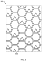
- an example mesh arrangement 900 is shown suitable for use with a wall bead according to the present invention.
- the mesh arrangement 900 comprises a mesh having teeth 902 formed therefrom.
- the teeth 902 are formed with the mesh during the manufacturing process.
- Teeth 902 formed with the mesh 900 preferably provide improved robustness of a connection of the mesh 900 to a wall surface and preferably aid improved contouring of the mesh 900 with non-flat wall surface, such as a curved wall surface for example.
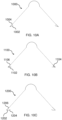
- the plan sectional view shown in FIG. 10A shows an alternate embodiment 1000 substantially as described with reference to FIG. 1C wherein the teeth 1002 are instead angled inwardly such that they form an approximately acute angle with their respective connection portion.
- Teeth 1002 such as those comprised within the alternate embodiment 1000 of FIG. 10A may provide a wall bead 1000 which is more difficult to remove from a wall surface, wherein an outward force placed on the wall bead 1000 causes the teeth 1002 thereon to grip the wall surface more robustly.
- the example embodiment 1100 shown in FIG. 10B is substantially as described for the embodiment 100 of FIG. 1C but instead comprises teeth formed of a first tooth 1102 and a smaller second tooth 1104, formed within the first tooth 1002, and having a smaller angle relative to the respective connection portion 1106.
- dually-formed teeth formed of a triangle within a triangle, for example, preferably provide improved gripping of a wall bead to a wall surface and therefore provide for more difficult removal.
- the alternate example embodiment 1200 of FIG. 10C is substantially as hereinbefore described with reference to FIG. 1C wherein the teeth are formed of a first tooth portion 1202 and a second tooth portion 1204 extending therefrom at an angle relative to the first tooth portion 1202.
- Such angled, or in some case curved, teeth can provide improved connection of a wall bead to a wall surface for more difficult removal.
- a right angle wall bead is represented.
- the wall bead comprises an acute or obtuse angle to better suit a wall to which the bead is intended to be applied.
- the corner of the wall to which the wall bead is applied may comprise a different angle at one point along the length of the corner compared to an angle at another point along the length of the corner.
- the present wall bead comprising the flexible mesh, is therefore arranged to suit a corner of any angle, or of mixed angles, and is preferably ideally suited to corners having a surface thereof which is non-flat, such as concave or convex.
- the wall bead is a rounded, or bullnose bead for producing a rounded corner of a wall.
- Other suitable forms of wall bead will be appreciated.
- Embodiments are shown having apertures extending along the connection portion or the solid panel portions intended for, for example, screws or nails.
- the formation, structure or frequency of the teeth is such that no other affixing means are required to affix the wall bead to a wall surface and such said embodiments may not comprise said screw or nail apertures.
Description
- The present invention relates to a wall bead for applying across two adjoining surfaces of a wall, such as a corner, prior to the application of a surface coating thereto.
- It is well known to apply a surface coating of plaster or other render material, to ceilings and other wall surfaces in buildings. Generally, prior to applying the plaster or the material, an elongate bead of metal is applied along external corners where two intersecting surfaces meet, in order to enable a good finish to be achieved to the corner. The bead also acts to strengthen and protect the corner.
-
US Patent No 4,876,837 discloses a typical corner bead which is formed from an elongate strip of sheet metal and comprises a rounded nose and two mounting flanges extending perpendicular to each other from the opposite sides of the nose. The mounting flanges are apertured to provide a key for the overlying plaster or render. - The corner bead is applied to a corner by passing nails or screws through the apertured mounting flanges into the underlying wall material. However, a disadvantage of this arrangement is that the underlying wall material is often too hard or too soft to readily accept nails or screws and thus the process of applying corner beads can be difficult and time consuming. In order to overcome this problem, it is has been proposed to attach corner beads using an adhesive. However, the corner beads have to be held in place whilst the adhesive sets and it will be appreciated that this is equally as difficult as permanently securing the corner beads. Another disadvantage of using adhesive is that the adhesive has to be allowed to set before the underlying wall is plastered or rendered.
-
US Patent No 5,778,617 discloses a corner bead which attempts to overcome the above-mentioned problems and which comprises a plurality of integral pre-formed barbs along its length for securing the corner bead to underlying wall surfaces formed of plasterboard or other drywall material. In use, when a corner bead is applied to the plasterboard the barbs penetrate the outer layer of the plasterboard and temporarily secure the corner bead to the corner whilst it is plastered over. A disadvantage of this arrangement is that the barbs extend substantially perpendicular to the bead and so once the bead has been fixed to the wall surface it can be very difficult to remove or reposition the bead without unduly damaging the underlying plasterboard. - Additional disadvantages shared by the previous solutions include the rigidity of the outwardly projecting flanges. Such flanges are unsuitable for walls having corners or varying shapes or angles and such, the purpose of the bead to provide a neat, continuous and robust corner of the wall, is eliminated.
- It is therefore desirable to provide a solution which overcomes the disadvantages of the current wall beads. Particularly it is desirable to provide a solution which provides improved ease of attachment to a wall, and in some cases more difficult removal, while providing improved flexibility.
-
DE 10 2006 053867 relates to a fixed edge plaster shine device having an integrated hook. -
WO 2011/023971 relates to a wall bead in accordance with the preamble of claim 1 for applying across two adjoining surfaces of a wall such as a corner, prior to the application of a surface coating thereto. -
DE 88 02 263 relates to a plaster edge protection rail for insulating boards made of rigid foam or the like. -
DE 10 2007 053473 relates to a metal element with at least one planar section in which a plurality of openings are formed. - In accordance with a first aspect of the present invention, there is provided a wall bead, the wall bead comprising: a central longitudinally extending portion having a first longitudinal edge and a second longitudinal edge opposing the first edge; a first planar panel extending from the first edge; a second planar panel extending from the second edge; a first connection portion extending from the first panel; and a second connection portion extending from the second panel; wherein the first connection portion and the second connection portion each comprise a plurality of teeth protruding therefrom and distributed along a longitudinal length thereof; and characterised in that the first and second panel each comprise a flexible mesh or woven material such that the first and second panel are arranged to conform to a contour of a wall surface.
- The mesh panels of the present invention preferably provide a level of flexibility in wall beads not previously permitted, with a robust wall attachment mechanism in the form of the teeth protruding from the connection portions. The term "mesh" will be understood by the skilled addressee in the context of the present invention as an interlaced net or lattice structure. A material, such as stainless steel, which is arranged in an interlaced network provides improved flexibility relative to the equivalent material arranged as a substantially continuous, unmeshed structure. Current wall beads may provide panels having regularly interspaced apertures specifically arranged to receive nails or screws. The skilled addressee will appreciate the difference between such panels and the panels of the present invention comprising a mesh or woven material.
- In some embodiments, the first panel and the second panel may each comprise a plurality of mesh portions separated by one or more solid portions. The surface area of the first and second panels to be occupied by said mesh portions may be selected during manufacturing to control a flexibility of said panels. A requirement for greater flexibility will require a greater surface area of said panels being formed of said mesh. An embodiment requiring maximum flexibility, for a particularly aggressive or acutely-angled wall corner for example, may comprise first and second panels formed entirely of said mesh. An embodiment requiring semi rigidity, such as for a gentle or curved wall corner may comprise first and second panels each having a first elongate mesh panel portion and a second elongate mesh panel portion separated by a solid panel portion located therebetween. In most embodiments the elongate mesh panel portions will be understood to extend along the length of the wall bead. The term "solid panel portion" will be understood to differentiate from the term "mesh panel portion" due to a lack of, or reduced number of, apertures of the solid panel portion relative to the mesh panel portion.
- In some embodiments, the first panel and/or the second panel may comprise teeth. In such embodiments said teeth may protrude from the mesh or, in embodiments comprising first and second panels having one or more solid panel portion, said teeth may protrude from said solid panel portions. In embodiments wherein the first and/or second panel comprises teeth, the teeth are preferably substantially the same as the teeth located on the connection portions. Embodiments will be appreciated wherein the teeth are not the same as the teeth located on the connection portions. For example, teeth located on mesh portions of the panels may be formed during formation of the mesh during manufacture. Punching apertures into the mesh may accompany formation of teeth during said punching process. In embodiments wherein the first and second panels comprise teeth, some preferable examples of said embodiments may comprise teeth opposing the teeth of the corresponding connection portion. For example, teeth protruding form the first panel may in some preferable embodiments oppose the teeth protruding from the first connection portion. Said opposing teeth preferably provide for a more robust connection of the wall bead to a wall surface such that the wall bead requires greater force to disconnect from said wall surface.
- In some embodiments the central portion may comprise one or more teeth. Preferably teeth located on the central portion may protrude from a surface of the central portion intended to engage a wall surface. In such embodiments, preferably the central portion comprises an elongate curved portion having a first and second longitudinal edge, a first planar portion extending from the first longitudinal edge and a second planar portion extending from the second longitudinal edge. Preferably the first and second planar portions form guide which aid in aligning the edge of the wall bead with a surface of a wall and also preferably provide improved lateral restraint. Preferably the central portion comprises teeth located on the elongate curved portion, the first planar portion and the second planar portion. Said teeth preferably aid in providing improved connection of the wall bead to a wall surface, and therefore providing more difficult removal.
- Embodiments will be appreciated wherein the first and second panels comprise a plurality of panel sections distributed along the length of the respective longitudinal edge of the central portion separated by a space. Wall beads having panels comprising a plurality of panel section preferably provide greater flexibility of the wall bead.
- In some embodiments, the teeth may comprise a first set of teeth arranged to extend from a surface of the first connection portion and the second connection portion, and a second set of teeth arranged to extend from a surface of the first connection portion and the second connection portion, the first set of teeth and the second set of teeth positioned in spaced pairs at longitudinal positions along the first connection portion and the second connection portion. In some embodiments, the teeth may comprise a first set of teeth arranged to extend from a surface of the first connection portion and the second connection portion, and a smaller second set of teeth, collocated with the first set of teeth and formed therefrom.
- In said embodiments, the second set of teeth may optionally extend from the surface at an angle of less than 90° relative to the surface.
- In some preferable embodiments, the teeth may be arranged to protrude from the respective connection portion in a single longitudinal direction along the respective connection portion. In such embodiments, the teeth may optionally extend from the respective connection portion surface at an angle of less than 90° relative to the surface.
- In some embodiments, the teeth may each comprise a pointed distal end and are generally triangular in shape. In other embodiments, the teeth may each comprise a generally straight distal end and generally trapezoid in shape. In some such embodiments, the teeth may each comprise a serrated edge having a non-linear profile. Embodiments will be appreciated wherein the teeth are any suitable shape and are arranged to puncture the surface of a wall substrate, such as for example plasterboard, following external force being applied thereto.
- The teeth may comprise a first portion proximate the connection portion or the mesh, and a second portion distal to the connection portion or the mesh, the first portion and the second portion being positioned at an angle relative to one another. In such embodiments, the second portion of the teeth is preferably angled relative to the first portion, the angle preferably being obtuse. The term "obtuse" in the context of the present invention will be understood to mean greater than 90° but less than 180°. Teeth comprising said angle preferably provide a more robust connection between the connection portion and the surface of a wall, such that once connected to a wall surface, the wall bead is more difficult to disconnect from said wall surface.
- Preferably a front surface of the first and second panels are angularly spaced about the central portion by an angle of less than 180°. More preferably, the angle is substantially 90°.
- Preferably the flexible mesh or woven material comprises one selected from the group: stainless steel; mild steel; galvanised metal. Such a material may be a minimesh.
- In preferable embodiments, the first connection portion and the second connection portion each comprise a connection portion material which is a continuous, unmeshed material. Preferably the connection portion material is one selected from the group: stainless steel; mild steel; galvanised metal.
- In preferable embodiments, the central portion comprises a central portion material which is a continuous, unmeshed material. Preferably the central portion material is one selected from the group: stainless steel; mild steel; galvanised metal.
- In the context of the present invention, the term "flexible" will be understood by the skilled addressee to mean flexible relative to the connection portion and/or the central portion, which in preferable embodiments are a continuous, unmeshed material. It will be appreciated that the first panel material and the second panel material may be the same as the central portion material and/or the connection portion material, but in such embodiments the mesh of the first panel material and the second panel material imparts greater flexibility upon the panels relative to the central portion and/or the connection portion.
- Preferably the central portion provides a bridging connection between the first panel and the second panel. In preferable embodiments the bridging connection comprises a generally semicircular profile.
- Specific embodiments will now be described by way of example only, and with reference to the accompanying drawings, in which:
-
FIG. 1A shows a front view of a first example embodiment of a wall bead according to the present invention; -
FIG. 1B shows a lateral view of the embodiment ofFIG. 1A ; -
FIG. 1C shows a sectional plan view of the embodiment ofFIG. 1A and FIG. 1B ; -
FIG. 2A shows a front view of a second example embodiment of a wall bead according to the present invention; -
FIG. 2B shows a lateral view of the embodiment ofFIG. 2A ; -
FIG. 2C shows a sectional plan view of the embodiment ofFIG. 2A and FIG. 2B ; -
FIG. 3A shows a front view of a third example embodiment of a wall bead according to the present invention; -
FIG. 3B shows a lateral view of the embodiment ofFIG. 3A ; -
FIG. 3C shows a sectional plan view of the embodiment ofFIG. 3A and FIG. 3B ; -
FIG. 4A shows a sectional plan view of fourth embodiment of a wall bead according to the present invention; -
FIG. 4B shows a sectional plan view of an alternate embodiment to that shown inFIG. 4A ; -
FIG. 5A shows a sectional plan view of fifth embodiment of a wall bead according to the present invention; -
FIG. 5B shows a sectional plan view of an alternate embodiment to that shown inFIG. 5A ; -
FIG. 6 shows a front view of a sixth example embodiment of a wall bead according to the present invention; -
FIG. 7A shows a front view of a seventh example embodiment of a wall bead according to the present invention; -
FIG. 7B shows a sectional plan view of the embodiment ofFIG. 7A ; -
FIG. 8A shows a front view of an eighth example embodiment of a wall bead according to the present invention; -
FIG. 8B shows a lateral view of the embodiment ofFIG. 8A ; -
FIG. 8C shows a sectional plan view of the embodiment ofFIG. 8A and FIG. 8B ; and -
FIG. 9 shows an enlarged view of an example mesh structure for use with the present invention. - Referring to
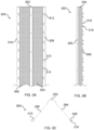
FIG. 1A , a front view of anexample embodiment 100 is shown of awall bead 100 according to the first aspect of the present invention. In the example 100 shown, thewall bead 100 comprises an elongatecentral portion 102 extending longitudinally along the centre of thewall bead 100. Extending outwardly, in a plane defined by a first direction, from thecentral portion 102 is a firstplanar panel 104 consisting of a foraminous, stainless steel mesh. Thefirst panel 104 is affixed to thecentral portion 102 along a first longitudinal edge thereof. Thewall bead 100 further comprises asecond mesh panel 106, substantially the same as thefirst mesh panel 104, extending from thecentral portion 102 in a plane defined by a second direction opposite the first direction. Thesecond panel 106 is affixed to the central portion along a second longitudinal edge thereof, the second edge opposing the first edge. Thefirst panel 104 and thesecond panel 106 are positioned in their respective planes defining an angle of around 90 degrees therebetween. - The
wall bead 100 of the embodiment shown further comprises afirst connection portion 108 extending from thefirst panel 104. Thefirst connection portion 108 is affixed to thefirst panel 104 along a longitudinal edge of thefirst panel 104 distal to thecentral portion 102. Thefirst connection portion 108 comprises a plurality ofapertures 112 spaced evenly along the length of thefirst connection portion 108. Theapertures 112 comprise an aperture diameter sized to receive a nail driven therethrough during fixing of thewall bead 100 to a corner surface of a plasterboard wall. Spaced evenly along thefirst connection portion 108, and protruding in a single longitudinal direction therefrom, are a plurality ofteeth 114, taking the form of stainless steel barbs each formed using a notch in thefirst connection portion 108. As can be seen fromFIG. 1B , thebarbs 114 protrude from a surface of thefirst connection portion 108 at an acute angle relative to the surface, the surface being intended to be directed toward a plasterboard wall for fixation of the wall bead thereto using thebarbs 114. - Extending from the
second panel 106, and affixed along a longitudinal edge thereof, is asecond connection portion 110 which is substantially a mirror image of thefirst connection portion 108. Thesecond connection portion 110 is affixed to an edge of thesecond panel 106 distal to thecentral portion 102. - As can be seen from the sectional plan view of
FIG. 1C , thecentral portion 102 forms a semicircular bridge between thefirst panel 104 and thesecond panel 106. In the embodiment shown, thefirst panel 104 and thesecond panel 106 each extend in a plane which is roughly 90 degrees relative the plane of the other of the two panels. As such, thebead 100 is ideally arranged to be positioned about a corner of a plasterboard wall. The flexible mesh of thefirst panel 104 and thesecond panel 106 are arranged to deviate from their respective planes shownFIG. 1C such that thepanels - In use, the
wall bead 100 shown is affixed to a corner of a plasterboard wall (not shown) prior to coating said plasterboard wall with plaster. Thecentral portion 102 acts to form a neat, continuous corner of a wall which is robust to wear and tear compared to the underlying plasterboard. Thebarbs 114 enable affixing of thebead 100 to the plasterboard with minimal effort and without specifically requiring the addition of nails through theapertures 112. The first andsecond panels bead 100 are highly flexible by virtue of the mesh. The enhanced flexibility of the first andsecond panels bead 100 to conform to a surface of the corner of plasterboard wall easily and with minimal effort. Thebead 100 may therefore be specifically suited to applications requiring a flexible beading with enhanced securing/affixing properties, such as those using a bespoke wall shape which may have, for example, a convex, concave, or otherwise non-flat surface. Simultaneous conforming of the bead to the non-flat plasterboard wall surface while fixation occurs is therefore provided. Said simultaneous action is key to providing a solution which is suited to applications requiring simple, fast and effective application of a wall bead to a non-flat surface of a plasterboard wall corner. -
FIG. 2A to FIG. 2C show asecond example embodiment 200 of awall bead 200 wherein thecentral portion 202 forms a longitudinal join between adjacent longitudinal edges of a first stainlesssteel mesh panel 204 and asecond mesh panel 206 substantially the same as thefirst panel 204. Eachpanel join 202 as can be seen in the sectional plan view ofFIG. 2C . Thebead 200 comprises afirst connection portion 208 extending from thefirst mesh panel 204 and asecond connection portion 210 extending from thesecond mesh panel 206, thesecond connection portion 210 being a mirror image of thefirst connection portion 208. As with thefirst embodiment 100 described in relation toFIG. 1A to FIG. 1C , theconnection portions second embodiment 200 comprise a plurality ofapertures 212 distributed at regular intervals along theconnection portions barbs 214 protruding from theconnection portions 214. Thebarbs 214 protrude from a surface of thefirst connection portion 208 and thesecond connection portion 210 at an acute angle relative to the surface, the surface being intended to be directed toward a plasterboard wall for fixation of the wall bead thereto using thebarbs 214. - In use, the
wall bead 200 shown inFIG. 2A to FIG. 2C is arranged to provide complete flexibility of the bead in situations wherein the relatively inflexiblecentral portion 102 of theprevious embodiment 100 may be undesirable. The continuous nature of the communication between thefirst panel 204 and thesecond panel 206 along thelongitudinal edge 202 permits maximum flexibility of the bead. - Referring to
FIG. 3A, FIG. 3B and FIG. 3C , athird embodiment 300 of a wall bead according to the present invention is shown wherein a push bead is provided arranged to be affixed to the corner of a wall by pushing thebead 300 into a wall substrate, such as plasterboard. Thewall bead 300 comprises acentral portion 302 and first and secondplanar panels embodiment 100 ofFIG. 1A to FIG. 1C . Thethird embodiment 300, however, comprises afirst connection portion 308 extending from the firstplanar panel 304 and asecond connection portion 310 extending from the secondplanar panel 306, the first andsecond connection portions rectangular grooves 312 therein, each having anupper surface 314 and alower surface 315. As can be seen from the lateral view ofFIG. 3B , thebead 300 also comprises a plurality ofteeth first connection portion 308 intended to be in contact with a wall surface. Thesecond connection portion 310 also comprises said plurality ofteeth 316, 318 (not shown). Two series ofteeth first series 316 extending from theupper surface 314 of thegrooves 312 perpendicular to the surface of therespective connection portion teeth 318 extend from thelower surface 315 of thegrooves 312 in a direction away from theupper surface 315 such that an acute angle is provided between the second series of theteeth 318 and the surface of therespective connection portion FIG. 3C , theteeth - Additional sectional plan views of alternative embodiments of the present invention can be seen in
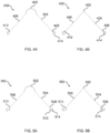
FIG. 4A, FIG. 4B, FIG. 5A and FIG. 5B . In theembodiments FIG. 4A and FIG. 4B , like numbering is used to represent equivalent parts. In eachembodiment longitudinally extending section 402 is shown having first and secondplanar panels planar panels second connection portion 408. 410 comprising a plurality ofteeth 414 protruding therefrom. Theembodiment 400 ofFIG. 4A comprises acentral portion 402 equivalent to that of theembodiment 100 ofFIG. 1A to FIG. 1C . Theembodiment 450 ofFIG. 4B comprises acentral portion 402 equivalent to that of theembodiment 200 ofFIG. 2A to FIG. 2C . In eachembodiment teeth 414 extend at an acute angle relative to a surface of therespective connection portion teeth 414 comprise a roughly trapezoid shape which may be suitable for particular wall substrates. - In the
embodiments FIG. 5A and FIG. 5B , like numbering is used to represent equivalent parts. In eachembodiment longitudinally extending section 502 is shown having first and secondplanar panels planar panels second connection portion 508. 510 comprising a plurality ofteeth 514 protruding therefrom. Theembodiment 500 ofFIG. 5A comprises acentral portion 502 equivalent to that of theembodiment 200 ofFIG. 2A to FIG. 2C . Theembodiment 550 ofFIG. 5B comprises acentral portion 502 equivalent to that of theembodiment 200 ofFIG. 2A to FIG. 2C . In eachembodiment teeth 514 extend at an acute angle relative to a surface of therespective connection portion teeth 514 comprise a roughly rectangular shape having aserrated surface 516, which may be suitable for particular wall substrates, such as more dense substrates or those comprising a cover material through which the tooth penetrates. Theserrated surface 516 permits easier entry of theteeth 514 into said substrate while maintaining the surface area of therectangular teeth 514. A relatively large surface area across the connection between the teeth and the wall surface, such as that provided by therectangular teeth 514, improves the robustness of said connection. Aserrated surface 516 provides the additional advantage of improved entry of saidteeth 514 into the wall substrate. - Referring to
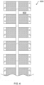
FIG. 6 , anexample embodiment 600 of a wall bead is shown having enhanced flexibility compared to theembodiment 100 ofFIG. 1A to FIG. 1C . Thewall bead 600 compriseslateral grooves 602 distributed along the panels such that the panels have improved flexibility and can therefore conform to the contour of a non-flat wall surface. - Referring to
FIG. 7A and FIG. 7B , anexample embodiment 700 of a semi-rigid wall bead in accordance with the present invention is shown, the semirigid wall bead 700 comprising a curvedcentral portion 702, a firstplanar panel 704 extending from a first longitudinal edge of thecentral portion 702, a secondplanar panel 706 extending from a second longitudinal edge of thecentral portion 702, the second longitudinal edge opposing the first longitudinal edge. The first and secondplanar panels mesh panel portion 710 separated by asolid panel portion 712 therebetween. Thesolid panel portion 712 of the first andsecond panels apertures 714 distributed along the length thereof. Extending from each even-numbered of saidapertures 714 toward an outermost edge of the respectivesolid panel portion 712 is aslit 716 each forming atooth 718 in thesolid panel portion 712. The outermost edge will be understood to be distal to thecentral portion 702. Extending from the secondmesh panel portion 710 is aconnection portion 720 which, in the example embodiment shown, is substantially the same as thesolid panel portion 712. - In use, the
solid panel portions 712 of theexample embodiment 700 ofFIG. 7A and FIG. 7B provide a semi-rigid structure arranged to be less flexible than embodiments comprising first and second panels consisting entirely of mesh. Such examples 700 may be more suitable for corners which are less aggressive or wherein the flexible nature of the mesh is less important than the structural integrity of the wall bead. Thesolid panel portion 712 in the embodiment shown comprisesteeth 718 which preferably cooperate with the teeth of theconnection portion 720 to provide improved connection to a wall. Embodiments will be appreciated wherein the solid panel portion does not comprise teeth. Embodiments will further be appreciated wherein the teeth of thesolid panel portion 712 and the teeth of theconnection portion 720 are angled such that the teeth of thesolid panel portion 712 oppose the corresponding teeth of theconnection portion 720. Such opposing of the teeth preferably provides improved connection of a wall bead to a wall. - Referring to
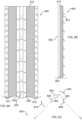
FIG. 8A to FIG. 8C , andexample embodiment 800 of a wall bead having toothed guides for easier alignment and improved lateral restraint is shown. Thewall bead 800 comprises an elongate central portion formed of a centralcurved portion 802 having a solid semicircular cross-section extending along the length of thecurved portion 802. Thecurved portion 802 comprises a first and second longitudinal edge extending along the length thereof. Extending outwardly from the first longitudinal edge of thecurved portion 802 is a first solidplanar panel 804 of the central portion. Extending outwardly from the second longitudinal edge of thecurved portion 802 is a second solidplanar panel 806 of the central portion. As can be seen inFIG. 8C , thefirst panel 804 of the central portion and thesecond panel 806 of the central portion are angled at roughly 90° to one another. Distributed along thecurved portion 802, thefirst panel 804 of the central portion and thesecond panel 806 of the central portion, and protruding therefrom, are a plurality ofteeth 808 being roughly triangular in shape. Extending from thefirst panel 804 of the central portion is a firstplanar mesh portion 810 and extending from thesecond panel 806 of the central portion is a secondplanar mesh portion 812. Extending from the firstplanar mesh portion 810 is afirst connection portion 814, and extending from the secondplanar mesh portion 812 is asecond connection portion 816. Each of the first andsecond connection portions planar mesh portions second connection portions first example embodiment 100 ofFIG. 1A to FIG. 1C . - In use, the first and second
planar panels wall bead 800 to a corner of a wall (not shown). Theteeth 808 act as anchor points for thewall bead 800 in the wall and provide lateral restraint against removal of thewall bead 800 from said wall. Upon rotation of thefirst panel 804 andfirst mesh portion 810 in thedirection 818 shown, arotational force 820 about the central portion causes the opposingsecond panel 806 and theteeth 808 thereon to engage with the wall more rigorously. As such, said consequentrotational action 820 preferably acts to cause thewall bead 800 to grip the wall surface more robustly and is therefore more difficult to remove. As an advantage, such an embodiment is preferably more difficult to move on or remove from a wall surface by accident during subsequent preparation of the wall surface to be coated with, for example, plaster. It will be understood that opposite forces to those described will cause equally improved gripping byteeth 808 of the opposingpanel 804 of the central portion. - Referring to
FIG. 9 , anexample mesh arrangement 900 is shown suitable for use with a wall bead according to the present invention. Themesh arrangement 900 comprises amesh having teeth 902 formed therefrom. Theteeth 902 are formed with the mesh during the manufacturing process.Teeth 902 formed with themesh 900 preferably provide improved robustness of a connection of themesh 900 to a wall surface and preferably aid improved contouring of themesh 900 with non-flat wall surface, such as a curved wall surface for example. - The plan sectional view shown in
FIG. 10A shows analternate embodiment 1000 substantially as described with reference toFIG. 1C wherein theteeth 1002 are instead angled inwardly such that they form an approximately acute angle with their respective connection portion.Teeth 1002 such as those comprised within thealternate embodiment 1000 ofFIG. 10A may provide awall bead 1000 which is more difficult to remove from a wall surface, wherein an outward force placed on thewall bead 1000 causes theteeth 1002 thereon to grip the wall surface more robustly. Theexample embodiment 1100 shown inFIG. 10B is substantially as described for theembodiment 100 ofFIG. 1C but instead comprises teeth formed of afirst tooth 1102 and a smallersecond tooth 1104, formed within thefirst tooth 1002, and having a smaller angle relative to therespective connection portion 1106. Such dually-formed teeth, formed of a triangle within a triangle, for example, preferably provide improved gripping of a wall bead to a wall surface and therefore provide for more difficult removal. Thealternate example embodiment 1200 ofFIG. 10C is substantially as hereinbefore described with reference toFIG. 1C wherein the teeth are formed of afirst tooth portion 1202 and asecond tooth portion 1204 extending therefrom at an angle relative to thefirst tooth portion 1202. Such angled, or in some case curved, teeth can provide improved connection of a wall bead to a wall surface for more difficult removal. - It will be appreciated that the above described embodiments are given by way of example only and that various modifications may be made to the described embodiments without departing from the scope of the invention as defined in the appended claims. For example, in the embodiments shown and described, a right angle wall bead is represented. Embodiments of the present invention will be appreciated wherein the wall bead comprises an acute or obtuse angle to better suit a wall to which the bead is intended to be applied. The corner of the wall to which the wall bead is applied may comprise a different angle at one point along the length of the corner compared to an angle at another point along the length of the corner. The present wall bead, comprising the flexible mesh, is therefore arranged to suit a corner of any angle, or of mixed angles, and is preferably ideally suited to corners having a surface thereof which is non-flat, such as concave or convex. Embodiments of the present invention will be appreciated wherein the wall bead is a rounded, or bullnose bead for producing a rounded corner of a wall. Other suitable forms of wall bead will be appreciated. Embodiments are shown having apertures extending along the connection portion or the solid panel portions intended for, for example, screws or nails. Embodiments will be appreciated wherein the formation, structure or frequency of the teeth is such that no other affixing means are required to affix the wall bead to a wall surface and such said embodiments may not comprise said screw or nail apertures.
Claims (15)
- A wall bead (100, 200, 300, 400, 500, 600), the wall bead (100, 200, 300, 400, 500, 600) comprising:a central longitudinally extending portion (102, 202, 302, 402, 502) having a first longitudinal edge and a second longitudinal edge opposing the first edge;a first planar panel (104, 204, 304, 404, 504) extending from the first edge;a second planar panel (106, 206, 306, 406, 506) extending from the second edge;a first connection portion (108, 208, 308, 408, 508) extending from the first panel (104, 204, 304, 404, 504); anda second connection (110, 210, 310, 410, 510) portion extending from the second panel (106, 206, 306, 406, 506);wherein the first connection portion (108, 208, 308, 408, 508) and the second connection portion (110, 210, 310, 410, 510) each comprise a plurality of teeth (114, 214, 316, 414, 514) protruding therefrom and distributed along a longitudinal length thereof; andcharacterised in that the first (104, 204, 304, 404, 504) and second panel (106, 206, 306, 406, 506) each comprise a flexible mesh or woven material such that the first (104, 204, 304, 404, 504) and second panel (106, 206, 306, 406, 506) are arranged to conform to a contour of a wall surface.
- A wall bead (100, 200, 300, 400, 500, 600) as claimed in claim 1, wherein the teeth (114, 214, 316, 414, 514) comprise a first set of teeth arranged to extend from a surface of the first connection portion (108, 208, 308, 408, 508) and the second connection portion (110, 210, 310, 410, 510), and a second set of teeth arranged to extend from a surface of the first connection portion (108, 208, 308, 408, 508) and the second connection portion (110, 210, 310, 410, 510), the first set of teeth and the second set of teeth positioned in spaced pairs at longitudinal positions along the first connection portion (108, 208, 308, 408, 508) and the second connection portion (110, 210, 310, 410, 510).
- A wall bead (100, 200, 300, 400, 500, 600) as claimed in claim 2, wherein the second set of teeth extend from the surface at an angle of less than 90° relative to the surface.
- A wall bead (100, 200, 300, 400, 500, 600) as claimed in claim 1, claim 2 or claim 3, wherein the teeth (114, 214, 316, 414, 514) each comprise a pointed distal end and are generally triangular in shape.
- A wall bead (100, 200, 300, 400, 500, 600) as claimed in claim 1, claim 2 or claim 3, wherein the teeth (114, 214, 316, 414, 514) each comprise a generally straight distal end and generally trapezoid in shape.
- A wall bead (100, 200, 300, 400, 500, 600) as claimed in any of claims 1 to 5, wherein the teeth (114, 214, 316, 414, 514) each comprise a serrated edge (516) having a non-linear profile.
- A wall bead (100, 200, 300, 400, 500, 600) as claimed in any one of claims 1 to 6, wherein a front surface of the first (104, 204, 304, 404, 504) and second panels (106, 206, 306, 406, 506) are angularly spaced about the central portion (102, 202, 302, 402, 502) by an angle of less than 180°.
- A wall bead (100, 200, 300, 400, 500, 600) as claimed in claim 7, wherein the angle is substantially 90°.
- A wall bead (100, 200, 300, 400, 500, 600) as claimed in any one of the preceding claims, wherein the flexible mesh or woven material is one selected from the group: stainless steel; mild steel; galvanised metal.
- A wall bead (100, 200, 300, 400, 500, 600) as claimed in any one of the preceding claims, wherein the first connection portion (108, 208, 308, 408, 508) and the second connection portion (110, 210, 310, 410, 510) each comprise a connection portion material which is a continuous, unmeshed material.
- A wall bead (100, 200, 300, 400, 500, 600) as claimed in claim 10 wherein the connection portion material is one selected from the group: stainless steel; mild steel; galvanised metal.
- A wall bead (100, 200, 300, 400, 500, 600) as claimed in any one of the preceding claims, wherein the central portion (102, 202, 302, 402, 502) comprises a central portion material which is a continuous, unmeshed material.
- A wall bead (100, 200, 300, 400, 500, 600) as claimed in claim 12, wherein the central portion material is one selected from the group: stainless steel; mild steel; galvanised metal.
- A wall bead (100, 200, 300, 400, 500, 600) as claimed in any one of the preceding claims, wherein the central portion (102, 202, 302, 402, 502) provides a bridging connection between the first panel (104, 204, 304, 404, 504) and the second panel (106, 206, 306, 406, 506).
- A wall bead (100, 200, 300, 400, 500, 600) as claimed in claim 14, wherein the bridging connection comprises a generally semicircular profile.
Applications Claiming Priority (2)
| Application Number | Priority Date | Filing Date | Title |
|---|---|---|---|
| GB1910659.0A GB2585937B (en) | 2019-07-25 | 2019-07-25 | Wall bead |
| PCT/GB2020/051331 WO2021014115A1 (en) | 2019-07-25 | 2020-06-03 | Wall plastering bead |
Publications (3)
| Publication Number | Publication Date |
|---|---|
| EP4004303A1 EP4004303A1 (en) | 2022-06-01 |
| EP4004303B1 true EP4004303B1 (en) | 2024-01-10 |
| EP4004303C0 EP4004303C0 (en) | 2024-01-10 |
Family
ID=67990464
Family Applications (1)
| Application Number | Title | Priority Date | Filing Date |
|---|---|---|---|
| EP20732272.8A Active EP4004303B1 (en) | 2019-07-25 | 2020-06-03 | Wall plastering bead |
Country Status (8)
| Country | Link |
|---|---|
| US (1) | US20220275650A1 (en) |
| EP (1) | EP4004303B1 (en) |
| CN (1) | CN114599846A (en) |
| AU (1) | AU2020318877A1 (en) |
| CA (1) | CA3148583A1 (en) |
| GB (1) | GB2585937B (en) |
| WO (1) | WO2021014115A1 (en) |
| ZA (1) | ZA202201237B (en) |
Families Citing this family (1)
| Publication number | Priority date | Publication date | Assignee | Title |
|---|---|---|---|---|
| US20230046179A1 (en) * | 2021-08-12 | 2023-02-16 | Noll/Norwesco Llc | Gripping cornerbead |
Family Cites Families (19)
| Publication number | Priority date | Publication date | Assignee | Title |
|---|---|---|---|---|
| US658386A (en) * | 1900-07-03 | 1900-09-25 | Ferris A Mitchell | Corner strip or bead. |
| US1748284A (en) * | 1924-06-26 | 1930-02-25 | Kalnian Steel Company Inc | Corner bead |
| US1804564A (en) * | 1930-05-31 | 1931-05-12 | Mcchesney David | Exterior corner connection for wall boards |
| US2904856A (en) * | 1957-05-21 | 1959-09-22 | George L Robinson | Corner bead |
| DE3805467A1 (en) * | 1988-02-22 | 1989-08-31 | Metal Deploye Belge Sa | Corner bead for insulating panels consisting of rigid foam or the like |
| US4876837A (en) | 1988-08-22 | 1989-10-31 | Usg Interiors, Inc. | Corner bead structure |
| CN2127944Y (en) * | 1991-06-07 | 1993-03-10 | 长沙板网制品厂 | Horned dinosaur bone for building |
| US5442886A (en) * | 1993-12-20 | 1995-08-22 | Iacobelli; Luigi | Prefabricated corner bead |
| US5778617A (en) * | 1995-10-27 | 1998-07-14 | Free; Gerald R. | Press-on corner bead |
| CN1231370A (en) * | 1998-04-08 | 1999-10-13 | 江木龙 | Corner protector |
| US6571520B2 (en) * | 2001-03-20 | 2003-06-03 | Trim-Tex, Inc. | Drywall-trimming strip having bullnose portion with minimal set-back requirement |
| DE102006053867A1 (en) * | 2006-11-14 | 2008-06-05 | Robert Baldus | Device, particularly fixed edge plaster shine for making clean plaster edges, has integrated barbed hook and is individually prestressed, where fixed edge plaster shine is put on corner to be plastered before applying plaster |
| DE102007053473A1 (en) * | 2007-11-09 | 2009-05-14 | Protektorwerk Florenz Maisch Gmbh & Co Kg | Metal element e.g. expanded metal, for producing e.g. pavement profile, has bar including material areas of metal element that are pulled apart within area between boundary planes and in direction parallel to boundary planes |
| US20110030297A1 (en) * | 2009-08-07 | 2011-02-10 | Robertson Frederick J | Cornerbead structure |
| GB2472108B (en) * | 2009-08-27 | 2011-07-13 | Budha Singh Dhinjan | Wall bead |
| CN201474211U (en) * | 2009-09-09 | 2010-05-19 | 浙江立鹏建设有限公司 | Angle bead protection device with mesh cloth |
| US20130186024A1 (en) * | 2012-01-25 | 2013-07-25 | Terry L. Rosentiel | Fiber composite corner bead |
| CN204418568U (en) * | 2014-12-26 | 2015-06-24 | 陈潇 | A kind of building operations location square staff |
| CN206769259U (en) * | 2017-05-22 | 2017-12-19 | 江苏建设控股集团有限公司 | A kind of metope external corner protector |
-
2019
- 2019-07-25 GB GB1910659.0A patent/GB2585937B/en active Active
-
2020
- 2020-06-03 CN CN202080063021.1A patent/CN114599846A/en active Pending
- 2020-06-03 US US17/629,710 patent/US20220275650A1/en active Pending
- 2020-06-03 EP EP20732272.8A patent/EP4004303B1/en active Active
- 2020-06-03 CA CA3148583A patent/CA3148583A1/en active Pending
- 2020-06-03 AU AU2020318877A patent/AU2020318877A1/en active Pending
- 2020-06-03 WO PCT/GB2020/051331 patent/WO2021014115A1/en active Application Filing
-
2022
- 2022-01-26 ZA ZA2022/01237A patent/ZA202201237B/en unknown
Also Published As
| Publication number | Publication date |
|---|---|
| CN114599846A (en) | 2022-06-07 |
| EP4004303A1 (en) | 2022-06-01 |
| WO2021014115A1 (en) | 2021-01-28 |
| GB201910659D0 (en) | 2019-09-11 |
| US20220275650A1 (en) | 2022-09-01 |
| CA3148583A1 (en) | 2021-01-28 |
| ZA202201237B (en) | 2023-06-28 |
| AU2020318877A1 (en) | 2022-02-24 |
| EP4004303C0 (en) | 2024-01-10 |
| GB2585937B (en) | 2023-05-10 |
| GB2585937A (en) | 2021-01-27 |
Similar Documents
| Publication | Publication Date | Title |
|---|---|---|
| US8875468B2 (en) | Wall bead | |
| EP1907649B1 (en) | Corner bead assembly and method of applying the same | |
| US5291717A (en) | Construction member and method for forming curved wall and the like | |
| US5647182A (en) | Corner cap with unitary prongs | |
| EP4004303B1 (en) | Wall plastering bead | |
| US7698867B1 (en) | Siding trim clip with triangular gripping pattern | |
| US9464433B1 (en) | Self-tightening splice | |
| OA20997A (en) | Wall plastering bead. | |
| US20230046179A1 (en) | Gripping cornerbead | |
| US20230046540A1 (en) | Grooved Cornerbead | |
| US11746804B2 (en) | Gripping bracket | |
| JP2017053100A (en) | Wall-covering corner material | |
| JP2001309531A (en) | Electric wire fixing means | |
| WO2004070133A1 (en) | Fixing method | |
| JPH0354501Y2 (en) | ||
| JP2001193225A (en) | Tile fixture and method for fixing tile using tile fixture | |
| AU2014203021B2 (en) | Angle bead clip | |
| GB2556161A (en) | Plaster bead | |
| JPH0334600A (en) | Wiring protective device | |
| WO2003080958A1 (en) | Edge reinforcement for fabricated structure | |
| GB2430699A (en) | A flexible plaster stop bead | |
| NZ514150A (en) | Mounting bracket | |
| AU6998701A (en) | Mounting bracket |
Legal Events
| Date | Code | Title | Description |
|---|---|---|---|
| STAA | Information on the status of an ep patent application or granted ep patent |
Free format text: STATUS: UNKNOWN |
|
| STAA | Information on the status of an ep patent application or granted ep patent |
Free format text: STATUS: THE INTERNATIONAL PUBLICATION HAS BEEN MADE |
|
| PUAI | Public reference made under article 153(3) epc to a published international application that has entered the european phase |
Free format text: ORIGINAL CODE: 0009012 |
|
| STAA | Information on the status of an ep patent application or granted ep patent |
Free format text: STATUS: REQUEST FOR EXAMINATION WAS MADE |
|
| 17P | Request for examination filed |
Effective date: 20220209 |
|
| AK | Designated contracting states |
Kind code of ref document: A1 Designated state(s): AL AT BE BG CH CY CZ DE DK EE ES FI FR GB GR HR HU IE IS IT LI LT LU LV MC MK MT NL NO PL PT RO RS SE SI SK SM TR |
|
| DAV | Request for validation of the european patent (deleted) | ||
| DAX | Request for extension of the european patent (deleted) | ||
| GRAP | Despatch of communication of intention to grant a patent |
Free format text: ORIGINAL CODE: EPIDOSNIGR1 |
|
| STAA | Information on the status of an ep patent application or granted ep patent |
Free format text: STATUS: GRANT OF PATENT IS INTENDED |
|
| INTG | Intention to grant announced |
Effective date: 20230531 |
|
| GRAS | Grant fee paid |
Free format text: ORIGINAL CODE: EPIDOSNIGR3 |
|
| GRAA | (expected) grant |
Free format text: ORIGINAL CODE: 0009210 |
|
| STAA | Information on the status of an ep patent application or granted ep patent |
Free format text: STATUS: THE PATENT HAS BEEN GRANTED |
|
| AK | Designated contracting states |
Kind code of ref document: B1 Designated state(s): AL AT BE BG CH CY CZ DE DK EE ES FI FR GB GR HR HU IE IS IT LI LT LU LV MC MK MT NL NO PL PT RO RS SE SI SK SM TR |
|
| REG | Reference to a national code |
Ref country code: GB Ref legal event code: FG4D |
|
| REG | Reference to a national code |
Ref country code: CH Ref legal event code: EP |
|
| REG | Reference to a national code |
Ref country code: DE Ref legal event code: R096 Ref document number: 602020024202 Country of ref document: DE |
|
| REG | Reference to a national code |
Ref country code: IE Ref legal event code: FG4D |
|
| U01 | Request for unitary effect filed |
Effective date: 20240212 |