EP4003945B1 - Dehydrogenation process and system with reactor re-sequencing - Google Patents
Dehydrogenation process and system with reactor re-sequencing Download PDFInfo
- Publication number
- EP4003945B1 EP4003945B1 EP20847637.4A EP20847637A EP4003945B1 EP 4003945 B1 EP4003945 B1 EP 4003945B1 EP 20847637 A EP20847637 A EP 20847637A EP 4003945 B1 EP4003945 B1 EP 4003945B1
- Authority
- EP
- European Patent Office
- Prior art keywords
- dehydrogenation
- reactors
- productivity
- modes
- sequence
- Prior art date
- Legal status (The legal status is an assumption and is not a legal conclusion. Google has not performed a legal analysis and makes no representation as to the accuracy of the status listed.)
- Active
Links
Images


Classifications
-
- B—PERFORMING OPERATIONS; TRANSPORTING
- B01—PHYSICAL OR CHEMICAL PROCESSES OR APPARATUS IN GENERAL
- B01J—CHEMICAL OR PHYSICAL PROCESSES, e.g. CATALYSIS OR COLLOID CHEMISTRY; THEIR RELEVANT APPARATUS
- B01J19/00—Chemical, physical or physico-chemical processes in general; Their relevant apparatus
- B01J19/24—Stationary reactors without moving elements inside
- B01J19/2415—Tubular reactors
- B01J19/2425—Tubular reactors in parallel
-
- B—PERFORMING OPERATIONS; TRANSPORTING
- B01—PHYSICAL OR CHEMICAL PROCESSES OR APPARATUS IN GENERAL
- B01J—CHEMICAL OR PHYSICAL PROCESSES, e.g. CATALYSIS OR COLLOID CHEMISTRY; THEIR RELEVANT APPARATUS
- B01J23/00—Catalysts comprising metals or metal oxides or hydroxides, not provided for in group B01J21/00
- B01J23/70—Catalysts comprising metals or metal oxides or hydroxides, not provided for in group B01J21/00 of the iron group metals or copper
- B01J23/76—Catalysts comprising metals or metal oxides or hydroxides, not provided for in group B01J21/00 of the iron group metals or copper combined with metals, oxides or hydroxides provided for in groups B01J23/02 - B01J23/36
- B01J23/825—Catalysts comprising metals or metal oxides or hydroxides, not provided for in group B01J21/00 of the iron group metals or copper combined with metals, oxides or hydroxides provided for in groups B01J23/02 - B01J23/36 with gallium, indium or thallium
-
- B—PERFORMING OPERATIONS; TRANSPORTING
- B01—PHYSICAL OR CHEMICAL PROCESSES OR APPARATUS IN GENERAL
- B01J—CHEMICAL OR PHYSICAL PROCESSES, e.g. CATALYSIS OR COLLOID CHEMISTRY; THEIR RELEVANT APPARATUS
- B01J8/00—Chemical or physical processes in general, conducted in the presence of fluids and solid particles; Apparatus for such processes
- B01J8/02—Chemical or physical processes in general, conducted in the presence of fluids and solid particles; Apparatus for such processes with stationary particles, e.g. in fixed beds
- B01J8/0242—Chemical or physical processes in general, conducted in the presence of fluids and solid particles; Apparatus for such processes with stationary particles, e.g. in fixed beds the fluid flow within the bed being predominantly vertical
- B01J8/025—Chemical or physical processes in general, conducted in the presence of fluids and solid particles; Apparatus for such processes with stationary particles, e.g. in fixed beds the fluid flow within the bed being predominantly vertical in a cylindrical shaped bed
-
- B—PERFORMING OPERATIONS; TRANSPORTING
- B01—PHYSICAL OR CHEMICAL PROCESSES OR APPARATUS IN GENERAL
- B01J—CHEMICAL OR PHYSICAL PROCESSES, e.g. CATALYSIS OR COLLOID CHEMISTRY; THEIR RELEVANT APPARATUS
- B01J8/00—Chemical or physical processes in general, conducted in the presence of fluids and solid particles; Apparatus for such processes
- B01J8/02—Chemical or physical processes in general, conducted in the presence of fluids and solid particles; Apparatus for such processes with stationary particles, e.g. in fixed beds
- B01J8/0285—Heating or cooling the reactor
-
- C—CHEMISTRY; METALLURGY
- C07—ORGANIC CHEMISTRY
- C07C—ACYCLIC OR CARBOCYCLIC COMPOUNDS
- C07C11/00—Aliphatic unsaturated hydrocarbons
- C07C11/02—Alkenes
- C07C11/08—Alkenes with four carbon atoms
- C07C11/09—Isobutene
-
- C—CHEMISTRY; METALLURGY
- C07—ORGANIC CHEMISTRY
- C07C—ACYCLIC OR CARBOCYCLIC COMPOUNDS
- C07C4/00—Preparation of hydrocarbons from hydrocarbons containing a larger number of carbon atoms
- C07C4/02—Preparation of hydrocarbons from hydrocarbons containing a larger number of carbon atoms by cracking a single hydrocarbon or a mixture of individually defined hydrocarbons or a normally gaseous hydrocarbon fraction
- C07C4/06—Catalytic processes
-
- C—CHEMISTRY; METALLURGY
- C07—ORGANIC CHEMISTRY
- C07C—ACYCLIC OR CARBOCYCLIC COMPOUNDS
- C07C5/00—Preparation of hydrocarbons from hydrocarbons containing the same number of carbon atoms
- C07C5/32—Preparation of hydrocarbons from hydrocarbons containing the same number of carbon atoms by dehydrogenation with formation of free hydrogen
- C07C5/327—Formation of non-aromatic carbon-to-carbon double bonds only
- C07C5/333—Catalytic processes
- C07C5/3332—Catalytic processes with metal oxides or metal sulfides
-
- C—CHEMISTRY; METALLURGY
- C07—ORGANIC CHEMISTRY
- C07C—ACYCLIC OR CARBOCYCLIC COMPOUNDS
- C07C5/00—Preparation of hydrocarbons from hydrocarbons containing the same number of carbon atoms
- C07C5/32—Preparation of hydrocarbons from hydrocarbons containing the same number of carbon atoms by dehydrogenation with formation of free hydrogen
- C07C5/327—Formation of non-aromatic carbon-to-carbon double bonds only
- C07C5/333—Catalytic processes
- C07C5/3335—Catalytic processes with metals
- C07C5/3337—Catalytic processes with metals of the platinum group
-
- B—PERFORMING OPERATIONS; TRANSPORTING
- B01—PHYSICAL OR CHEMICAL PROCESSES OR APPARATUS IN GENERAL
- B01J—CHEMICAL OR PHYSICAL PROCESSES, e.g. CATALYSIS OR COLLOID CHEMISTRY; THEIR RELEVANT APPARATUS
- B01J2208/00—Processes carried out in the presence of solid particles; Reactors therefor
- B01J2208/02—Processes carried out in the presence of solid particles; Reactors therefor with stationary particles
- B01J2208/021—Processes carried out in the presence of solid particles; Reactors therefor with stationary particles comprising a plurality of beds with flow of reactants in parallel
-
- B—PERFORMING OPERATIONS; TRANSPORTING
- B01—PHYSICAL OR CHEMICAL PROCESSES OR APPARATUS IN GENERAL
- B01J—CHEMICAL OR PHYSICAL PROCESSES, e.g. CATALYSIS OR COLLOID CHEMISTRY; THEIR RELEVANT APPARATUS
- B01J2208/00—Processes carried out in the presence of solid particles; Reactors therefor
- B01J2208/02—Processes carried out in the presence of solid particles; Reactors therefor with stationary particles
- B01J2208/023—Details
- B01J2208/024—Particulate material
- B01J2208/025—Two or more types of catalyst
-
- C—CHEMISTRY; METALLURGY
- C07—ORGANIC CHEMISTRY
- C07C—ACYCLIC OR CARBOCYCLIC COMPOUNDS
- C07C2523/00—Catalysts comprising metals or metal oxides or hydroxides, not provided for in group C07C2521/00
- C07C2523/16—Catalysts comprising metals or metal oxides or hydroxides, not provided for in group C07C2521/00 of arsenic, antimony, bismuth, vanadium, niobium, tantalum, polonium, chromium, molybdenum, tungsten, manganese, technetium or rhenium
- C07C2523/24—Chromium, molybdenum or tungsten
- C07C2523/26—Chromium
Definitions
- the present invention relates generally to cyclic dehydrogenation processes and systems with multiple dehydrogenation reactors operating in alternating and synchronized production/regeneration modes. These processes include the dehydrogenation of alkanes over fixed beds of catalyst such as supported chromium, gallium, or platinum/tin or the like.
- the invention involves sequencing or re-sequencing the reactors to reduce fluctuation in production rates over a system cycle which allows productivity to be increased.
- Hydrocarbon dehydrogenation processes are conventionally practiced with systems having compressors and absorbers serving a plurality of sequenced reactors which operate in alternating production/regeneration modes over a system repeating cycle.
- a process for catalytic dehydrogenation of hydrocarbons carried out wherein the catalyst is alternately contacted with a hydrocarbon charge and subjected to regeneration by combustion of carbonaceous deposits resulting from dehydrogenation of the hydrocarbon charge.
- Each of the operations are carried out in a battery of reactors operated in a timed sequence of substantially equal periods of hydrocarbon conversion and catalyst regeneration.
- the sequence of operations for each reactor is as follows: (1) hydrocarbon dehydrogenation, (2) steam purging to free catalyst and reaction vessel of hydrocarbon products, (3) catalyst regeneration in oxygen-containing gas, (4) evacuation and (5) reduction of oxidized catalyst in hydrogencontaining gas.
- An exemplary form of the dehydrogenation system is illustrated in Figure 2 of GB 794,089 . As there is shown, the system comprises five reactors, R, which are operated in a cycle such that two are simultaneously on stream for catalytic dehydrogenation, two are being subjected to regeneration of catalyst therein, and one is in a stage involving an operation such as evacuation, steam purge, hydrogen reduction or valve changes.
- the diagram in Figure 3 of GB 794,089 shows how the reactors are operated on an approximately 22.5 minute cycle.
- FIG. 823,626 Another multi-reactor dehydrogenation system is shown in GB 823,626 .
- two or more 3-reactor batteries are used.
- An exemplary dehydrogenation system is illustrated in Figure 2 of GB 823,626 .
- the system comprises six reactors, R, which are arranged in two batteries of three reactors each and are operated in a sequence such that two, i.e., one reactor of each battery, are simultaneously on stream for catalytic dehydrogenation, two are being subjected to regeneration of catalyst therein, and two are in a stage involving an operation such as evacuation, steam purge, hydrogen reduction or valve changes.
- FIG. 3 of GB 823,626 shows how the reactors are operated on a 15 minute repeating cycle. It will be noted from an inspection of the cycle chart of Figure 3 of GB 823,626 that reactors 1 and 4, 2 and 5 and 3 and 6 are always in the same phase of a cycle. The desirability of such arrangements according to the GB 823,626 specification is dictated by the fact that the paired reactors are opposite each other, as shown in Figure 2 of GB 823,626 . Thus the gaseous materials charged to the paired reactors, and the gaseous materials withdrawn therefrom, will have equal distances of travel to the mains conducting the gases to and from the unit. The GB 823,626 specification further notes that staggered cycle times may be desirable in terms of reducing demands on associated auxiliaries such as pumps, compressors and the like since only one reactor at a time is making a transition.
- auxiliaries such as pumps, compressors and the like since only one reactor at a time is making a transition.
- productivity differences between reactors in a multi- reactor system can also lead to inefficiency, productivity and yield losses when the downstream product recovery equipment capacity, notably absorber capacity, is exceeded or underutilized.
- product recovery capacity When product recovery capacity is exceeded, dehydrogenation product is flared and lost.
- absorbers When absorbers are underutilized, hydrogen is sorbed unnecessarily, increasing energy requirements of the system.
- a preferred system for implementing the present invention is a multi-fixed bed, adiabatic endothermic reaction system known in the art as a Houdry dehydrogenation system as is shown in GB 794,089 and GB 823,626 .
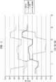
- Figure 1 is a plot of isobutylene yield over time for different reactor sequences over a system repeating cycle in a seven reactor system operating on a twenty-two (22) minute system cycle. It is seen in an initial sequence, prior to re-sequencing, the system exhibits a yield delta of about 8% or so, but that after re-sequencing, the yield delta is reduced to half of that or less; while peak productivity is lowered by about 5% on a relative basis, corresponding to 2.5% yield reduction.
- productivity may be increased in the re-sequenced system by increasing feed rates of hydrocarbon, by raising temperature of the hydrocarbon charge, by raising the regeneration air temperature or decreasing inlet pressure to produce 5% more product on an hourly basis with the same equipment as is shown in the dashed productivity line in Figure 1 .
- the invention may be realized in various ways by determining productivity of the various reactors and making adjustments to increase productivity. For instance, in a relatively simple system limited by a downstream product compressor to a yield value of 50, having 4 reactors, 2 reactors exhibiting yields of 50 operating simultaneously in dehydrogenation and regeneration modes alternating with two reactors having yield values of 40 operating simultaneously in dehydrogenation and regeneration modes over a cycle, the peak yield value will be 50 and the yield delta will be 10 over a system repeating operating cycle. If the reactors are re-sequenced over an operating cycle, with 1 reactor having a yield value of 50 and 1 reactor having a yield value of 40 being operating simultaneously in the same modes, the peak yield value is 45 and the yield delta goes away. Since the system can handle a yield value of 50, productivity can be increased by increasing feed rates of hydrocarbon, by raising temperature of the hydrocarbon charge, by raising the regeneration air temperature and so forth. Additional capacity is provided with no capital expense and only incremental operating expense.
- the number of reactors on-line at any given time is more or less the same prior to and after re-sequencing; However, it is also possible to sequester an over-active reactor (hot spot) or an underperforming reactor in order to bring the system into better balance, if so desired.
- an over-active reactor hot spot
- an underperforming reactor in order to bring the system into better balance, if so desired.
- Characteristic peak productivity refers to the aggregate maximum productivity of the reactors at a given point in time during a production cycle at a given feed rate, temperatures of operation and so forth.
- the characteristic peak productivity of the re-sequenced reactors may be calculated instead of measured, if so desired.
- Characteristic productivity delta is the difference between the aggregate maximum productivity of the reactors and the aggregate minimum productivity of the reactors during a system dehydrogenation cycle at a given feed rate, temperatures of operation and so forth.
- the minimum and maximum productivities of the re-sequenced reactors may be calculated instead of measured, if so desired.
- Liquid hourly space velocity based solely on the dehydrogenation reactant feed and is calculated as the hourly volumetric flow rate of liquid dehydrogenation reactant to the system divided by the volume of dehydrogenation catalyst beds in the multistage system, that is, in units of hr -1 .
- LHSV Liquid hourly space velocity
- percent refers to weight percent of a component or relative value to an initial value.
- Productivity of the system at any given time refers to the aggregate rate of dehydrogenation product produced by the reactor system by the reactors operating in dehydrogenation mode, in kg per hour or in like units.
- productivity is conveniently represented graphically by yield as is seen in Figure 1 , or may be approximated by conversion under a given set of conditions.
- Terminology to the effect that the characteristic productivity delta of the re-sequenced system is at least 25% lower than as compared with the characteristic productivity delta of the initial system sequence refers to the change in the difference between the aggregate peak and minimum productivity over a system cycle.
- the initial system cycle has a peak yield of 50% and a minimum yield of 40% over a cycle and the re-sequenced system has a peak yield of 47.5% and a minimum of 42.5%
- we refer to the characteristic productivity delta as decreasing from 10 to 5 or by 50% as compared to the initial system sequence.
- the re-sequenced system has a characteristic productivity delta of 3.6/7.8 or 46% lower as compared to the initial sequence.
- the characteristic productivity delta of the re-sequenced system is 3.6/47.3 or 7.6% of the characteristic peak productivity of the re-sequenced system.
- Figures 5 and 6 Complete repeating system cycles are shown in Figures 5 and 6 .
- Sequence “Sequence”, “re-sequence” and like terminology refers to the temporal order in which the various reactors are operated in a dehydrogenation mode before being switched to a regeneration mode of the reactor.
- Figure 5 shows a reactor sequence for the system cycle of 7 reactors as 1, 3, 5, 7, 2, 4, 6, while Figure 6 shows a reactor sequence of 1, 5, 4, 2, 7, 3, 6.
- the timed sequence is completed, the system cycle is repeated.
- the present invention may be applied to any suitable cyclical gas phase dehydrogenation process, for example, as described generally in United States Patent No. 4,172,854 to Ellis et al.
- Dehydrogenation processes which may be re-sequenced in accordance with the invention thus include isobutane to isobutylene; butane to butenes and butadiene; propionitrile to acrylonitrile; propionaldehyde to acrolein; ethyl chloride to vinyl chloride; methyl isobutyrate to methyl methacylate; 2 or 3-chlorobutene-1 or 2,3-dichlorobutane to chloroprene; ethyl pyridine to vinyl pyridine; ethylbenzene to styrene; isopropylbenzene to ⁇ -methyl styrene; ethylchlorohexane to styrene; cyclohexane to
- the preferred compounds to be dehydrogenated are hydrocarbons with a particularly preferred class being acyclic non-quaternary hydrocarbons having 3 to 5 carbon atoms or ethyl benzene and the preferred products are isobutene, propene, n-butene-1 or 2, butadiene-1,3vinyl acetylene, 2-methyl-1-butene, 3-methyl-1-butene, 3-methyl-2-butene, isoprene, styrene or mixtures thereof.
- Especially preferred as feed are isobutane, n-butane, isopentane, ethyl benzene mixtures thereof such as hydrocarbon mixtures containing these compounds in at least 50 mol percent.
- Suitable catalysts are described in Ullman's Encyclopedia of Industrial Chemistry, Hydrogenation and Dehydrogenation, Domenico Sanfilippo and Paul N. Rylander, Ed. Volume 18, PP. 451-471 Published Online: 15 OCT 2009, DOI: 10.1002/14356007.a13_487.pub2, Copyright ⁇ 2002 by Wiley-VCH Verlag GmbH & Co. KgaA and the references cited therein.
- the catalyst formulation includes promotion with alkali metals, which is fundamental for increasing the chromium active sites and decreasing the surface acidity (of both chromium and aluminum oxides). Potassium has the best effect if provided in the right amount. Typically, a volcano-shape curve of activity and selectivity is obtained by increasing the potassium content.
- Pt/Sn is supported either on alumina or on either ZnAl 2 O 4 or MgAl 2 O 4 .
- the catalyst is promoted with alkali metals and further promoters.
- Sn is to improve activity, selectivity, and stability because it neutralizes the acidity of supports, interacts electronically with Pt, and reduces the ensemble effect that favors coke formation.
- Increasing the loading of Pt + Sn, increasing the Sn/Pt ratio, or increasing the temperature of the reduction reaction causes the system to shift from separated phases towards the formation of Pt-Sn alloys.
- the catalyst preserves some bifunctional (acidic and noble-metal) activity, resulting in a moderate tendency to skeletal isomerization (e.g., isobutyl to n-butyl).
- Some characteristics of the catalysts have significant impact on the industrial implementation:
- the Pt/Sn catalysts undergo a double-mechanism ageing through coke fouling and sintering.
- the Pt/Sn catalysts can tolerate a coke build-up of several percentage points, preserving enough catalytic activity for allowing a period "on stream" of several hours/days before mandating a regeneration.
- the two promoted and optimized catalytic systems show comparable performances in terms of selectivity to olefins.
- a periodical regeneration with air is mandatory for both catalysts to burn off the coke.
- the catalyst will therefore undergo a cycle during which it will be exposed to a hydrocarbon atmosphere, followed by a period in the presence of oxygen (and/or some steam). It must therefore keep its morphological, structural, and chemical stability under severe hydrothermal conditions.
- the length of the time on hydrocarbon stream is distinctive of the selected active phase: typical values are minutes/hours for Cr catalysts and hours/days for the Pt ones.
- gallium (Ga) catalysts may be employed, as is seen in United States Patent Application Publication No. 2019/0126242 of Xing et al. with or without additional catalyst metals present. See United States Patent No. 5,219,816 to Zhou et al. which discloses Ga/Pt dehydrogenation catalysts.
- the catalyst beds may be undiluted, i.e. consist entirely of the supported active catalyst, or diluted with inert material if so desired and/or include a heat-generating material as is disclosed in United States Patent Nos.: 7,622,623 ; 7,973,207 ; 8,188,328 ; and 9,725,380 .
- the inert material may be, for example, a granular, alpha-alumina material of similar particle size to the supported catalyst.
- the heat generating material may include a metal selected from the group consisting of copper, chromium, molybdenum, vanadium, cerium, yttrium, scandium, tungsten, manganese, iron, cobalt, nickel, silver, bismuth and combinations thereof.
- Exemplary carriers for the heat-generating material include, but are not limited to, various aluminum oxides or hydroxides such as aluminum trihydroxide, boehmite, pseudo-boehmite, gibbsite, bayerite, transition aluminas or alpha-alumina, silica/alumina, silica, silicates, aluminates such as calcium aluminate or barium hexyluminate, calcined hydrotalcites, zeolites, zinc oxide, chromium oxides, magnesium oxides and combinations thereof.
- various aluminum oxides or hydroxides such as aluminum trihydroxide, boehmite, pseudo-boehmite, gibbsite, bayerite, transition aluminas or alpha-alumina, silica/alumina, silica, silicates, aluminates such as calcium aluminate or barium hexyluminate, calcined hydrotalcites, zeolites, zinc oxide, chromium oxides, magnesium oxide
- the heat-generating material may further comprise a promoter, such as an alkali, an alkaline earth metal, lithium, sodium, potassium, rubidium, cesium, beryllium, magnesium, calcium, strontium, zirconium, barium and a combination thereof.
- a promoter such as an alkali, an alkaline earth metal, lithium, sodium, potassium, rubidium, cesium, beryllium, magnesium, calcium, strontium, zirconium, barium and a combination thereof.
- the dehydrogenation reaction may be carried out in a gas phase at atmospheric pressure, superatmospheric pressure or at sub-atmospheric pressure.
- the total pressure of the system will normally be about atmospheric pressure or sub-atmospheric pressure. Generally the total pressure will be between about 101.3 kPa (1 p.s.i.a.) and about 618.5 kPa (75 p.s.i.a.). Preferably, the total pressure will be less than about 446.1 kPa (50 p.s.i.a.).
- the temperature of the dehydrogenation reaction will generally be in a range of about 350°C to 700°C with excellent results being obtained in the range of 400°C to 650°C.
- the gaseous reactants can be conducted through the reaction chamber at a fairly wide range of flow rates.
- the optimum flow rates will be dependent upon such variables as the temperature of reaction, pressure, particle size of the catalyst, and so forth. Desirable flow rates may be established by one skilled in the art.
- the flow rates will be within the range of about 0.10 to 10 liquid volumes of the organic compound to be dehydrogenated per volume of dehydrogenation zone containing catalyst per hour (referred to as LHSV).
- LHSV liquid volumes of the organic compound to be dehydrogenated per volume of dehydrogenation zone containing catalyst per hour
- the LHSV will be between 0.15 and about 5.
- the volume of a fixed bed dehydrogenation zone containing the catalyst is that original void volume of reactor space containing catalyst.
- the dehydrogenation is carried out in a series of cycles which comprise dehydrogenation of a suitable feed over the catalysts of the invention under the conditions as defined for a period of time, usually about 6 to 12 minutes followed by a regeneration cycle during which the coke deposited from the dehydrogenation is burnt off.
- the regeneration can be longer or shorter than the dehydrogenation cycle as needed to remove the coke, usually about 6 to 12 minutes will be sufficient.
- the coke is removed by passing oxygen at a temperature of 550°C to 650°C over the catalyst.
- a convenient source of oxygen is air, however, pure oxygen or a mixture of oxygen with inert gases, such as nitrogen, either in the same or different proportions as air, can be used.
- At least two reactors are concurrently operated in a dehydrogenation production mode and at least two reactors are in various stages of regeneration.
- the overall repeating dehydrogenation/regeneration sequence for the system may be about 20-25 minutes for a chrome/alumina catalyzed fixed bed reactor.
- a typical cycle of each reactor includes operating the reactor in a dehydrogenation mode for about 10 minutes, followed by regeneration including sequentially a steam purge, regeneration with air and optionally fuel gas, evacuation, and catalyst reduction. Steam purging continues for about 1 minute, regeneration with air and optionally fuel gas is carried out for about 10 minutes, evacuation of the reactors is accomplished in about 30 seconds and the catalyst is reduced with hydrogen for about 1 minute.
- Suitable reaction systems which may be re-sequenced in accordance with the present invention include those seen in GB 794,089 and GB 823,626 , as well as the reactor system shown schematically in Figures 2 , 3 of the present application which is a chromia catalyzed gas phase dehydrogenation system for producing isobutylene from isobutane.
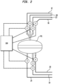
- FIG. 2 there is shown in Figure 2 a catalytic dehydrogenation reactor R1 connected in a battery of other reactors, R2 through R7, shown in Figure 3 .
- Reactor R1 is connected to a hydrocarbon charge feed line 12, a product discharge line 14, a steam line 16, an air regeneration line 18, a vacuum line 20, a reduction line 22, as well as a discharge line 24 for discharging of the gas from regeneration.
- reactor R1 Operation of reactor R1 is controlled via a plurality of valves V and output from the reactor is sampled via a port S to determine productivity.
- the valves are connected to a digital controller 100 which sequences the various steps in each of the various reactors in the reaction system, as described below in connection with Figure 3 .
- Each of reactors R2 through R7 are likewise provided with valves V and a sampling port S and are connected to controller 100 in the same manner as R1 and operate the same way.
- controller 100 connected to the valves, V, by way of dashed lines as indicated in the diagram. Connection to controller 100 are shown schematically only for the seven valves of reactor R1 ; it being appreciated that the valving on the other reactors is similarly connected and controlled by controller 100. Controller 100 is a DelataV DCS controller, model no. SD+ digital controller. If so desired, a second controller may be used to provide additional control integrity to critical features such as a Triconex controller, model 3008. Both can be utilized concurrently and are represented in the Figure collectively simply as controller 100.
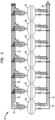
- system 10 comprises seven reactors, R1 through R7, which are operated in a cycle such that three are simultaneously on stream for catalytic dehydrogenation, three are being subjected to regeneration of catalyst therein, and one is in a stage involving an operation such as evacuation, steam purge, hydrogen reduction or valve changes.
- the diagram in Figure 5 shows how the reactors are operated on a twenty-two (22) minute (Appx.) cycle; it will be understood that the same operation can be carried out on a somewhat longer or a somewhat shorter cycle period.
- cycle time for a single system cycle is conveniently represented in two modes, dehydrogenation extending to regeneration which, for purposes of Figures 5 , 6 , includes purging, air regeneration and reduction of the catalyst bed.
- Figures 5 , 6 While it is seen in Figures 5 , 6 that equal numbers of reactors are in dehydrogenation and regeneration modes at any given time in a cycle, the system may be sequenced such that more reactors are in dehydrogenation mode than regeneration mode at a given point in time in a cycle if so desired. That is Figures 5 , 6 show roughly a 3-3-1 distribution between dehydrogenation and regeneration modes with one reactor in transition, however, the system could be sequenced in a 4-2-1 distribution between dehydrogenation and regeneration modes if that would provide better productivity balance in the system.
- the hydrocarbon charge is fed to the battery of reactors by means of a line 12 connecting through suitable branch lines and valving arrangements to each of said reactors R1-R7 in the series; the motor operated valves therein being opened and closed at the appropriate time by the operation of a cycle controller 100.
- the hydrocarbon conversion products will be withdrawn from the system as by means of a line 14 also suitably connected with each of the reactors of the series by suitable branch lines and valving arrangement.
- the reactor effluent from line 14 is subjected to the series of steps for recovery of the desired products, including the use of a downstream product compressor and an absorber tower (not shown).
- each reactor is on stream for dehydrogenation for 9-10 minutes and is on regeneration for 9-10 minutes or so including purging and valve changes.
- 40-50% of the total time of the cycle is devoted to actual on-stream production of desired hydrocarbon products while roughly equal time is used for regeneration, purging and valve operation.
- the system is conveniently controlled with a digital controller 100 connected to the valves, V, by way of dashed lines as indicated in the diagram. Connection to controller 100 are shown schematically only for the seven valves of reactor R1 ; it being appreciated that the valving on the other reactors is similarly connected and controlled by controller 100.
- each reactor in Figures 2 , 3 is determined by sampling the branch lines from each reactor to output line 14 as indicated by the S designations and comparing with the hydrocarbon charge stream to the reactors.
- Means for determining reactor performance can be on-line or off line and include any suitable analytical technique such as chromatography, IR, or any suitable analytical technique.
- Sampling ports, S may be used to obtain a sample for off-line or on-line analysis by chromatography, NMR, spectrometry and so forth, or may be used for determining productivity on-line by way of optical, infra-red, or other spectral detectors, if so desired.
- System 10 is operated such that the operating limit of the downstream product compressor (as well as the other components such as the regeneration air compressor) is capable of accommodating peak productivity during the 22 minute cycle.
- peak production is seen at the beginning of a cycle and a yield delta of 8 or so is seen at mid-cycle.
- a yield delta of 8 or so is seen at mid-cycle.
- productivity is increased by simply raising temperature, all other things being equal, productivity may be increased to the dashed line of Figure 1 without exceeding the compressor limit.
- productivity can be increased following resequencing by increasing feed rates of hydrocarbon, by raising temperature of the hydrocarbon charge, by raising the regeneration air temperature and so forth since the peak yield is reduced.
- An increase in productivity of 5.5% generates millions of dollars in additional revenue.
- the reactor system of Figures 2 , 3 was operated in a reactor cycle of approximately twenty-two (22) minutes in an initial reactor sequence wherein each reactor alternated between a dehydrogenation (production) mode and regeneration mode as indicated in Table 2 and Figure 5 .
- the system of Figure 3 was re-sequenced to the sequence of Table 3 and Figure 6 .
- the re-sequencing and subsequent increase in productivity boosts output anywhere from about 2-10% and more using the same reactors, even though peak conversion is lower as noted above.
- Figure 7 is a diagram showing downstream product compressor turbine speed and temperature before and after re-sequencing.
- the invention allows one to increase downstream turbine speed by 20% or more and raise temperatures by 10% or more without causing an upset in the system.
- the re-sequencing methodology is based on determining the productivity characteristics of each reactor and sequencing them so as to reduce system productivity deltas over the system cycle, including reducing peak rates. While any particular calculation method may be employed, it is particularly convenient to base re-sequencing calculations on yield data for all of the reactors for a given feed rate and set of operating conditions.
- the present invention is directed to a method of operating a dehydrogenation system according to claim 1 with a plurality of dehydrogenation reactors alternating between dehydrogenation modes and regeneration modes in a timed sequence in a system cycle comprising: (a) operating the plurality of dehydrogenation reactors in an initial system sequence having an initial characteristic peak productivity over the course of a system cycle; (b) determining the productivity characteristics of each of the dehydrogenation reactors; (c) re-sequencing the reactors to operate in a second system sequence having a re-sequenced characteristic peak productivity lower than that of said initial characteristic peak productivity ; and (d) increasing the re-sequenced characteristic peak productivity to a re-sequenced operating level to thereby increase system productivity over a system cycle as compared with operation in the initial system sequence.
- the method of the invention preferably includes one or more of the process features listed below:
- the invention also relates to a dehydrogenation system according to claim 17 comprising: (a) a plurality of dehydrogenation reactors valved to operate in alternating dehydrogenation modes and regeneration modes in a timed sequence in a system cycle by way of the plurality of valves; (b) a programmable digital controller connected to the plurality of valves for sequencing the reactors; and (c) means for determining the productivity characteristics of each reactor over a system cycle, which is the aggregate rate of dehydrogenation product produced by the reactor system by the reactors operating in dehydrogenation mode.
- the digital controller is operable to re-sequence the reactors via a pluratlity of valves to reduce either characteristic peak productivity or characteristic productivity deltas over a system cycle.
- the dehydrogenation system of the invention preferably includes one or more of the features listed immediately below:
Landscapes
- Chemical & Material Sciences (AREA)
- Organic Chemistry (AREA)
- Chemical Kinetics & Catalysis (AREA)
- Physics & Mathematics (AREA)
- Fluid Mechanics (AREA)
- Engineering & Computer Science (AREA)
- General Chemical & Material Sciences (AREA)
- Oil, Petroleum & Natural Gas (AREA)
- Materials Engineering (AREA)
- Organic Low-Molecular-Weight Compounds And Preparation Thereof (AREA)
- Low-Molecular Organic Synthesis Reactions Using Catalysts (AREA)
Description
- The present invention relates generally to cyclic dehydrogenation processes and systems with multiple dehydrogenation reactors operating in alternating and synchronized production/regeneration modes. These processes include the dehydrogenation of alkanes over fixed beds of catalyst such as supported chromium, gallium, or platinum/tin or the like. The invention involves sequencing or re-sequencing the reactors to reduce fluctuation in production rates over a system cycle which allows productivity to be increased.
- Hydrocarbon dehydrogenation processes are conventionally practiced with systems having compressors and absorbers serving a plurality of sequenced reactors which operate in alternating production/regeneration modes over a system repeating cycle. There is shown, for example, in
GB 794,089 Figure 2 ofGB 794,089 Figure 3 ofGB 794,089 - Another multi-reactor dehydrogenation system is shown in
GB 823,626 GB 823,626 Figure 2 ofGB 823,626 Figure 3 ofGB 823,626 Figure 3 ofGB 823,626 reactors GB 823,626 Figure 2 ofGB 823,626 GB 823,626 - Other dehydrogenation systems with programmable controllers are seen in
United States Patent Nos. 4,581,339 and7,271,307 , as well asWO 2018/203233 . - It is appreciated from the prior art that multiple alternating reactors in a dehydrogenation system are on a fixed sequence of operation, that is, the reactors are always operated in the same successive order. This is based, in part, on the assumption that reactor performance in terms of conversion is equivalent in reactors of the same construction having the same catalyst, feed and operating conditions. It has been found, however, that like reactors may not perform in a substantially identical manner, especially as the catalyst ages. Significant differences can arise in pressure/volume requirements and productivity, which are not unrelated in a gaseous dehydrogenation system because the product stream has an additional mole of hydrogen for each mole of dehydrogenation product produced. Differences in pressure drop/volume requirements may overtax the downstream product compressor or upstream regeneration air compressor when multiple reactors exhibiting high productivity are operated concurrently in a production mode. This leads to system shut down when horsepower limitations are reached; and therefore limits productivity based on peak production over a cycle.
- Likewise, productivity differences between reactors in a multi- reactor system can also lead to inefficiency, productivity and yield losses when the downstream product recovery equipment capacity, notably absorber capacity, is exceeded or underutilized. When product recovery capacity is exceeded, dehydrogenation product is flared and lost. When absorbers are underutilized, hydrogen is sorbed unnecessarily, increasing energy requirements of the system.
- It has been found that by re-sequencing reactors in an alternating cyclical multi-reactor dehydrogenation system that substantial and unexpected increases in productivity are achieved. In fact, production rates are maximized by reducing peak conversion of the system in a repeating cycle. Aggregate productivity of the reactors is balanced to run closer to compressor capacities for an entire cycle and process swings are reduced, improving absorber performance. In a preferred embodiment, the invention involves resequencing the reactors to reduce peak conversion and reduce productivity deltas over a system cycle. A preferred system for implementing the present invention is a multi-fixed bed, adiabatic endothermic reaction system known in the art as a Houdry dehydrogenation system as is shown in
GB 794,089 GB 823,626 - The invention is better appreciated by reference to
Figure 1 which is a plot of isobutylene yield over time for different reactor sequences over a system repeating cycle in a seven reactor system operating on a twenty-two (22) minute system cycle. It is seen in an initial sequence, prior to re-sequencing, the system exhibits a yield delta of about 8% or so, but that after re-sequencing, the yield delta is reduced to half of that or less; while peak productivity is lowered by about 5% on a relative basis, corresponding to 2.5% yield reduction. Inasmuch as the system is limited by peak productivity prior to re-sequencing, productivity may be increased in the re-sequenced system by increasing feed rates of hydrocarbon, by raising temperature of the hydrocarbon charge, by raising the regeneration air temperature or decreasing inlet pressure to produce 5% more product on an hourly basis with the same equipment as is shown in the dashed productivity line inFigure 1 . - The invention may be realized in various ways by determining productivity of the various reactors and making adjustments to increase productivity. For instance, in a relatively simple system limited by a downstream product compressor to a yield value of 50, having 4 reactors, 2 reactors exhibiting yields of 50 operating simultaneously in dehydrogenation and regeneration modes alternating with two reactors having yield values of 40 operating simultaneously in dehydrogenation and regeneration modes over a cycle, the peak yield value will be 50 and the yield delta will be 10 over a system repeating operating cycle. If the reactors are re-sequenced over an operating cycle, with 1 reactor having a yield value of 50 and 1 reactor having a yield value of 40 being operating simultaneously in the same modes, the peak yield value is 45 and the yield delta goes away. Since the system can handle a yield value of 50, productivity can be increased by increasing feed rates of hydrocarbon, by raising temperature of the hydrocarbon charge, by raising the regeneration air temperature and so forth. Additional capacity is provided with no capital expense and only incremental operating expense.
- In many embodiments the number of reactors on-line at any given time is more or less the same prior to and after re-sequencing; However, it is also possible to sequester an over-active reactor (hot spot) or an underperforming reactor in order to bring the system into better balance, if so desired.
- Further details and advantages will become apparent from the discussion which follows.
- The invention is described in detail below with reference to the drawings wherein:
-
Figure 1 is a plot of yield of isobutylene from isobutane over time in a multi-reactor system having a cycle time of about twenty-two (22) minutes; -
Figure 2 is a schematic view of an individual dehydrogenation reactor connected to a digital controller as part of a battery of reactors in accordance with the present invention; -
Figure 3 is a partial schematic view showing a battery of reactors of the type shown inFigure 2 (all of which are connected to the controller as inFigure 2 ) which may be re-sequenced with the digital controller in accordance with the invention; -
Figure 4 is a histogram showing yield of each of the reactors ofFigure 3 during operation in a dehydrogenation mode; -
Figure 5 is a diagram illustrating alternating production/regeneration times for seven reactors in a dehydrogenation system operating on a twenty-two (22) minute cycle in an initial sequence; -
Figure 6 is a diagram illustrating alternating production/regeneration times for seven reactors in a dehydrogenation system operating on a twenty-two (22) minute cycle after re-sequencing; and -
Figure 7 is a diagram showing downstream product compressor temperature and turbine speed (first stage compressor) before and after re-sequencing. - The invention is described in detail below in connection with the Figures for purposes of illustration, only. The invention is defined in the appended claims. Terminology used throughout the specification and claims herein is given its ordinary meaning as supplemented by the discussion immediately below, for example, "conversion", " selectivity" and yield are related by the mathematical definition X(conversion) * S(selectivity) = Y(yield), all calculated on a weight or molar basis; e.g. in a certain reaction, 90% of substance A is converted (consumed), but only 80% of it is converted to the desired substance B and 20% to undesired by-products, so conversion of A is 90%, selectivity for B 80% and yield of substance B is 72% (= 90% * 80%).
- Characteristic peak productivity refers to the aggregate maximum productivity of the reactors at a given point in time during a production cycle at a given feed rate, temperatures of operation and so forth. The characteristic peak productivity of the re-sequenced reactors may be calculated instead of measured, if so desired.
- Characteristic productivity delta is the difference between the aggregate maximum productivity of the reactors and the aggregate minimum productivity of the reactors during a system dehydrogenation cycle at a given feed rate, temperatures of operation and so forth. The minimum and maximum productivities of the re-sequenced reactors may be calculated instead of measured, if so desired.
- Liquid hourly space velocity ("LHSV") based solely on the dehydrogenation reactant feed and is calculated as the hourly volumetric flow rate of liquid dehydrogenation reactant to the system divided by the volume of dehydrogenation catalyst beds in the multistage system, that is, in units of hr-1. For purposes of Calculation of LHSV, the liquid density at atmospheric pressure and the boiling point of the reactant is used.
- Unless otherwise indicated, "percent", "%" or like terminology refers to weight percent of a component or relative value to an initial value.
- Productivity of the system at any given time refers to the aggregate rate of dehydrogenation product produced by the reactor system by the reactors operating in dehydrogenation mode, in kg per hour or in like units. For a given hydrocarbon feed rate, productivity is conveniently represented graphically by yield as is seen in
Figure 1 , or may be approximated by conversion under a given set of conditions. - Generally speaking, terminology to the effect that the re-sequenced characteristic peak productivity is from 2% to 20% lower as compared to the initial characteristic peak productivity of the system refers to the productivity difference as compared to the characteristic initial peak productivity level. Thus, if peak yield decreases from 50% to 47.5% under a given set of conditions, we refer to the peak productivity as decreasing by 2.5/50 or 5% and so forth.
- Terminology to the effect that the characteristic productivity delta of the re-sequenced system is at least 25% lower than as compared with the characteristic productivity delta of the initial system sequence refers to the change in the difference between the aggregate peak and minimum productivity over a system cycle. Thus, the initial system cycle has a peak yield of 50% and a minimum yield of 40% over a cycle and the re-sequenced system has a peak yield of 47.5% and a minimum of 42.5%, we refer to the characteristic productivity delta as decreasing from 10 to 5 or by 50% as compared to the initial system sequence.
- When sequencing the reactors to achieve a productivity delta less than a certain value, the aggregate maximum and aggregate minimum production over a cycle is considered. Thus, a cycle having a peak productivity of 100 units and a minimum productivity of 80 units is said to have a productivity delta of 20 units or 20% of the peak productivity.
- It will be appreciated from the foregoing and the discussion which follows that changes in characteristic peak productivity and characteristic productivity deltas can be conveniently expressed in percentages based on yield or conversion data from the reactors of the system. Thus, referring to
Figure 1 and Table 1, the re-sequenced system has a characteristic productivity delta of 3.6/7.8 or 46% lower as compared to the initial sequence. Moreover, the characteristic productivity delta of the re-sequenced system is 3.6/47.3 or 7.6% of the characteristic peak productivity of the re-sequenced system. - Complete repeating system cycles are shown in
Figures 5 and6 . "Sequence", "re-sequence" and like terminology refers to the temporal order in which the various reactors are operated in a dehydrogenation mode before being switched to a regeneration mode of the reactor. Thus,Figure 5 shows a reactor sequence for the system cycle of 7 reactors as 1, 3, 5, 7, 2, 4, 6, whileFigure 6 shows a reactor sequence of 1, 5, 4, 2, 7, 3, 6. When the timed sequence is completed, the system cycle is repeated. - The present invention may be applied to any suitable cyclical gas phase dehydrogenation process, for example, as described generally in
United States Patent No. 4,172,854 to Ellis et al. Dehydrogenation processes which may be re-sequenced in accordance with the invention thus include isobutane to isobutylene; butane to butenes and butadiene; propionitrile to acrylonitrile; propionaldehyde to acrolein; ethyl chloride to vinyl chloride; methyl isobutyrate to methyl methacylate; 2 or 3-chlorobutene-1 or 2,3-dichlorobutane to chloroprene; ethyl pyridine to vinyl pyridine; ethylbenzene to styrene; isopropylbenzene to α-methyl styrene; ethylchlorohexane to styrene; cyclohexane to benzene; ethane to ethylene to acetylene; propane to propylene or methyl acetylene or allene; isopentane to isoanylene and isoprene; n-butene to butadiene-1,3 and vinyl acetylene; methyl butene to isoprene; cyclopentane to cyclopentene and cyclopentadiene; n-octane to ethyl benzene and orthoxylene; monomethylheptanes to xylenes; ethyl acetate to vinyl acetate; 2,4,4-trimethylpentane to xylenes; and the like. The preferred compounds to be dehydrogenated are hydrocarbons with a particularly preferred class being acyclic non-quaternary hydrocarbons having 3 to 5 carbon atoms or ethyl benzene and the preferred products are isobutene, propene, n-butene-1 or 2, butadiene-1,3vinyl acetylene, 2-methyl-1-butene, 3-methyl-1-butene, 3-methyl-2-butene, isoprene, styrene or mixtures thereof. Especially preferred as feed are isobutane, n-butane, isopentane, ethyl benzene mixtures thereof such as hydrocarbon mixtures containing these compounds in at least 50 mol percent. - Suitable catalysts are described in Ullman's Encyclopedia of Industrial Chemistry, Hydrogenation and Dehydrogenation, Domenico Sanfilippo and Paul N. Rylander, Ed. and the references cited therein.
- Two large families of catalysts for the dehydrogenation of alkanes (based on Cr and Pt, respectively) do not differ substantially in terms of activity and selectivity but rather in the quality of some byproducts and in the treatment needed to complete the regeneration after the combustion of the coke. The maximum level of coke accumulation and consequently the time length needed for the reaction step before the regeneration depend on the nature of the particular catalyst used. In addition, the phenomena that lead to the irreversible deactivation (sintering, volatilization of the active components, and transformations of the morphology or the state of the support) are typically connected to the chemical types that characterize the various catalysts.
- With respect to Chromium-Based Catalysts, two supports are most widely used, ZrO2, which shows low acidity and high thermal stability, and transition aluminas (δ-θ), which are selected as actual supports for commercial catalysts. The catalyst formulation includes promotion with alkali metals, which is fundamental for increasing the chromium active sites and decreasing the surface acidity (of both chromium and aluminum oxides). Potassium has the best effect if provided in the right amount. Typically, a volcano-shape curve of activity and selectivity is obtained by increasing the potassium content. The nature of the active site is debated: Cr3+, both Cr3+ and Cr2+, and coordinatively unsaturated Cr2+ have been indicated as playing a role in the catalytic activity. For dehydrogenation of isobutane on Cr2O3/Al2O3, a Langmuir-Hinshelwood-type of kinetic equation is proposed, where it is assumed that the adsorption of isobutane represents the slow stage of the reaction and that no competition with adsorption of hydrogen exists.
- With respect to Platinum-Tin-Based Catalysts, typically, Pt/Sn is supported either on alumina or on either ZnAl2O4 or MgAl2O4. The catalyst is promoted with alkali metals and further promoters. The role of Sn is to improve activity, selectivity, and stability because it neutralizes the acidity of supports, interacts electronically with Pt, and reduces the ensemble effect that favors coke formation. Increasing the loading of Pt + Sn, increasing the Sn/Pt ratio, or increasing the temperature of the reduction reaction causes the system to shift from separated phases towards the formation of Pt-Sn alloys. The catalyst preserves some bifunctional (acidic and noble-metal) activity, resulting in a moderate tendency to skeletal isomerization (e.g., isobutyl to n-butyl). Some characteristics of the catalysts have significant impact on the industrial implementation: The Pt/Sn catalysts undergo a double-mechanism ageing through coke fouling and sintering. The Pt/Sn catalysts can tolerate a coke build-up of several percentage points, preserving enough catalytic activity for allowing a period "on stream" of several hours/days before mandating a regeneration. The two promoted and optimized catalytic systems (Pt-Sn/Al2O3 and Cr2O3/Al2O3) show comparable performances in terms of selectivity to olefins. A periodical regeneration with air is mandatory for both catalysts to burn off the coke. The catalyst will therefore undergo a cycle during which it will be exposed to a hydrocarbon atmosphere, followed by a period in the presence of oxygen (and/or some steam). It must therefore keep its morphological, structural, and chemical stability under severe hydrothermal conditions. The length of the time on hydrocarbon stream is distinctive of the selected active phase: typical values are minutes/hours for Cr catalysts and hours/days for the Pt ones.
- Likewise, gallium (Ga) catalysts may be employed, as is seen in
United States Patent Application Publication No. 2019/0126242 of Xing et al. with or without additional catalyst metals present. SeeUnited States Patent No. 5,219,816 to Zhou et al. which discloses Ga/Pt dehydrogenation catalysts. - The catalyst beds may be undiluted, i.e. consist entirely of the supported active catalyst, or diluted with inert material if so desired and/or include a heat-generating material as is disclosed in
United States Patent Nos.: 7,622,623 ;7,973,207 ;8,188,328 ; and9,725,380 - The dehydrogenation reaction may be carried out in a gas phase at atmospheric pressure, superatmospheric pressure or at sub-atmospheric pressure. The total pressure of the system will normally be about atmospheric pressure or sub-atmospheric pressure. Generally the total pressure will be between about 101.3 kPa (1 p.s.i.a.) and about 618.5 kPa (75 p.s.i.a.). Preferably, the total pressure will be less than about 446.1 kPa (50 p.s.i.a.). The temperature of the dehydrogenation reaction will generally be in a range of about 350°C to 700°C with excellent results being obtained in the range of 400°C to 650°C. The gaseous reactants can be conducted through the reaction chamber at a fairly wide range of flow rates. The optimum flow rates will be dependent upon such variables as the temperature of reaction, pressure, particle size of the catalyst, and so forth. Desirable flow rates may be established by one skilled in the art. Generally the flow rates will be within the range of about 0.10 to 10 liquid volumes of the organic compound to be dehydrogenated per volume of dehydrogenation zone containing catalyst per hour (referred to as LHSV). Usually the LHSV will be between 0.15 and about 5. For calculation, the volume of a fixed bed dehydrogenation zone containing the catalyst is that original void volume of reactor space containing catalyst. The dehydrogenation is carried out in a series of cycles which comprise dehydrogenation of a suitable feed over the catalysts of the invention under the conditions as defined for a period of time, usually about 6 to 12 minutes followed by a regeneration cycle during which the coke deposited from the dehydrogenation is burnt off. The regeneration can be longer or shorter than the dehydrogenation cycle as needed to remove the coke, usually about 6 to 12 minutes will be sufficient. The coke is removed by passing oxygen at a temperature of 550°C to 650°C over the catalyst. A convenient source of oxygen is air, however, pure oxygen or a mixture of oxygen with inert gases, such as nitrogen, either in the same or different proportions as air, can be used.
- In a typical embodiment, at least two reactors are concurrently operated in a dehydrogenation production mode and at least two reactors are in various stages of regeneration. The overall repeating dehydrogenation/regeneration sequence for the system may be about 20-25 minutes for a chrome/alumina catalyzed fixed bed reactor. A typical cycle of each reactor includes operating the reactor in a dehydrogenation mode for about 10 minutes, followed by regeneration including sequentially a steam purge, regeneration with air and optionally fuel gas, evacuation, and catalyst reduction. Steam purging continues for about 1 minute, regeneration with air and optionally fuel gas is carried out for about 10 minutes, evacuation of the reactors is accomplished in about 30 seconds and the catalyst is reduced with hydrogen for about 1 minute. Suitable reaction systems which may be re-sequenced in accordance with the present invention include those seen in
GB 794,089 GB 823,626 Figures 2 ,3 of the present application which is a chromia catalyzed gas phase dehydrogenation system for producing isobutylene from isobutane. - Referring to
Figures 2 ,3 there is shown inFigure 2 a catalytic dehydrogenation reactor R1 connected in a battery of other reactors, R2 through R7, shown inFigure 3 . Reactor R1 is connected to a hydrocarboncharge feed line 12, aproduct discharge line 14, asteam line 16, anair regeneration line 18, avacuum line 20, areduction line 22, as well as adischarge line 24 for discharging of the gas from regeneration. - Operation of reactor R1 is controlled via a plurality of valves V and output from the reactor is sampled via a port S to determine productivity. The valves are connected to a
digital controller 100 which sequences the various steps in each of the various reactors in the reaction system, as described below in connection withFigure 3 . Each of reactors R2 through R7 are likewise provided with valves V and a sampling port S and are connected tocontroller 100 in the same manner as R1 and operate the same way. - The system is conveniently controlled with a
digital controller 100 connected to the valves, V, by way of dashed lines as indicated in the diagram. Connection tocontroller 100 are shown schematically only for the seven valves of reactor R1; it being appreciated that the valving on the other reactors is similarly connected and controlled bycontroller 100.Controller 100 is a DelataV DCS controller, model no. SD+ digital controller. If so desired, a second controller may be used to provide additional control integrity to critical features such as a Triconex controller, model 3008. Both can be utilized concurrently and are represented in the Figure collectively simply ascontroller 100. - It is appreciated from the diagram, that resequencing is enabled by the digital controller, since 49 valves must be sequenced on the reactors alone in order to operate the system effectively.
- As there is shown in
Figure 3 ,system 10 comprises seven reactors, R1 through R7, which are operated in a cycle such that three are simultaneously on stream for catalytic dehydrogenation, three are being subjected to regeneration of catalyst therein, and one is in a stage involving an operation such as evacuation, steam purge, hydrogen reduction or valve changes. The diagram inFigure 5 shows how the reactors are operated on a twenty-two (22) minute (Appx.) cycle; it will be understood that the same operation can be carried out on a somewhat longer or a somewhat shorter cycle period. The diagrams and cycle times are shown in approximation, that is, cycle time for a single system cycle is conveniently represented in two modes, dehydrogenation extending to regeneration which, for purposes ofFigures 5 ,6 , includes purging, air regeneration and reduction of the catalyst bed. - While it is seen in
Figures 5 ,6 that equal numbers of reactors are in dehydrogenation and regeneration modes at any given time in a cycle, the system may be sequenced such that more reactors are in dehydrogenation mode than regeneration mode at a given point in time in a cycle if so desired. That isFigures 5 ,6 show roughly a 3-3-1 distribution between dehydrogenation and regeneration modes with one reactor in transition, however, the system could be sequenced in a 4-2-1 distribution between dehydrogenation and regeneration modes if that would provide better productivity balance in the system. - Referring again to
Figures 2 ,3 , the hydrocarbon charge is fed to the battery of reactors by means of aline 12 connecting through suitable branch lines and valving arrangements to each of said reactors R1-R7 in the series; the motor operated valves therein being opened and closed at the appropriate time by the operation of acycle controller 100. The hydrocarbon conversion products will be withdrawn from the system as by means of aline 14 also suitably connected with each of the reactors of the series by suitable branch lines and valving arrangement. The reactor effluent fromline 14 is subjected to the series of steps for recovery of the desired products, including the use of a downstream product compressor and an absorber tower (not shown). - In order to purge the reactors and the catalyst herein at the end of the on-stream cycle, steam is admitted to the system as by means of a
line 16 connected by suitable valved lines to each of the reactors R. Following the steam purge, a regenerating medium is introduced for removing contaminating deposit from the catalyst in the reactors, the medium being supplied to the appropriate reactor R1-R7 from asupply line 18 connected through suitable branch lines and valving arrangements for each of the reactors. Usually air or air diluted with flue gas is utilized as the regenerating medium, being raised to required temperature and pressure. While in some instances the reduction of the oxidized catalyst following regeneration can be effected by hydrocarbon charge, it is preferred in the operation of the present system to effect such reduction by means of hydrogen. Accordingly, following evacuation of the reactor subsequent to regeneration throughline 20 and appropriate valve connections, hydrogen is admitted throughline 22 and is appropriate connections. As shown,lines - The flue gas from regeneration is discharged through
line 24 and its valved branch lines connecting to each of the reactors. Thus, as shown inFigures 5 ,6 , each reactor is on stream for dehydrogenation for 9-10 minutes and is on regeneration for 9-10 minutes or so including purging and valve changes. In other words, 40-50% of the total time of the cycle is devoted to actual on-stream production of desired hydrocarbon products while roughly equal time is used for regeneration, purging and valve operation. The system is conveniently controlled with adigital controller 100 connected to the valves, V, by way of dashed lines as indicated in the diagram. Connection tocontroller 100 are shown schematically only for the seven valves of reactor R1; it being appreciated that the valving on the other reactors is similarly connected and controlled bycontroller 100. - Conventional operating systems for dehydrogenation systems with multiple synchronized reactors generally assume that the reactors, being more or less identical have more or less the same productivity, so that changing sequences is not necessary. The various reactors in the system have different productivities, even though they are of the same design. This is appreciated by reference to
Figure 4 which is a histogram of yields of reactors R1 - R7 during operation in a roughly ten minute dehydrogenation mode during production. For purposes of determining production rates, average yields may be used. It is seen that yields may vary by ten percentage points or more. - The performance of each reactor in
Figures 2 ,3 is determined by sampling the branch lines from each reactor tooutput line 14 as indicated by the S designations and comparing with the hydrocarbon charge stream to the reactors. Means for determining reactor performance can be on-line or off line and include any suitable analytical technique such as chromatography, IR, or any suitable analytical technique. Sampling ports, S, may be used to obtain a sample for off-line or on-line analysis by chromatography, NMR, spectrometry and so forth, or may be used for determining productivity on-line by way of optical, infra-red, or other spectral detectors, if so desired. -
System 10 is operated such that the operating limit of the downstream product compressor (as well as the other components such as the regeneration air compressor) is capable of accommodating peak productivity during the 22 minute cycle. In an initial sequence shown inFigure 1 , peak production is seen at the beginning of a cycle and a yield delta of 8 or so is seen at mid-cycle. Once re-sequenced under the same operating conditions, one reduces the peak yield by around 2.5% corresponding to a productivity reduction of around 5% while lowering the yield delta as shown onFigure 1 . If productivity is increased by simply raising temperature, all other things being equal, productivity may be increased to the dashed line ofFigure 1 without exceeding the compressor limit. As shown onFigure 1 , peak yield is reduced 2.5%, so that productivity of the system can be increased 5.5%:Table 1 - Re-Sequencing Productivity Increase Initial Re-Sequenced Average Yield (%) 45.4 45.4 Peak Yield (%) 49.8 47.3 Min Yield (%) 42.0 43.7 Yield delta (%) 7.8 3.6 Reduced Peak yield (%) 2.5 - While the initial and resequenced reactors have the same average yield, since the system can handle a peak yield value of approximately 50, productivity can be increased following resequencing by increasing feed rates of hydrocarbon, by raising temperature of the hydrocarbon charge, by raising the regeneration air temperature and so forth since the peak yield is reduced. The increased productivity thus realized = 2.5/45.4 or 5.5%. An increase in productivity of 5.5% generates millions of dollars in additional revenue.
- The reactor system of
Figures 2 ,3 was operated in a reactor cycle of approximately twenty-two (22) minutes in an initial reactor sequence wherein each reactor alternated between a dehydrogenation (production) mode and regeneration mode as indicated in Table 2 andFigure 5 . After determining the productivity of each reactor and system productivity when operating in the initial sequence, the system ofFigure 3 was re-sequenced to the sequence of Table 3 andFigure 6 . The re-sequencing and subsequent increase in productivity boosts output anywhere from about 2-10% and more using the same reactors, even though peak conversion is lower as noted above.Table 2 - Initial Reactor Sequence (1, 3, 5, 7, 2, 6) Reactor # 1 2 3 4 5 6 7 Dehydro Start (seconds) 728 175 912 359 1096 543 1280 Regen Start (seconds) 8 745 193 930 377 1114 561 Table 3 - Re-Sequenced System (1, 5, 4, 2, 7, 3, 6) Reactor # 1 2 3 4 5 6 7 Dehydro Start (seconds) 728 1281 359 1096 912 543 175 Regen Start (seconds) 8 561 930 377 193 1114 745 - By re-sequencing, it is possible to operate a downstream compressor at a higher rate and use higher regeneration air temperatures since it is not necessary to accommodate higher peak rates. This is shown in
Figure 7 , which is a diagram showing downstream product compressor turbine speed and temperature before and after re-sequencing. The invention allows one to increase downstream turbine speed by 20% or more and raise temperatures by 10% or more without causing an upset in the system. - As is appreciated from the foregoing description and the appended drawings, the re-sequencing methodology is based on determining the productivity characteristics of each reactor and sequencing them so as to reduce system productivity deltas over the system cycle, including reducing peak rates. While any particular calculation method may be employed, it is particularly convenient to base re-sequencing calculations on yield data for all of the reactors for a given feed rate and set of operating conditions.
- Generally speaking, the present invention is directed to a method of operating a dehydrogenation system according to
claim 1 with a plurality of dehydrogenation reactors alternating between dehydrogenation modes and regeneration modes in a timed sequence in a system cycle comprising: (a) operating the plurality of dehydrogenation reactors in an initial system sequence having an initial characteristic peak productivity over the course of a system cycle; (b) determining the productivity characteristics of each of the dehydrogenation reactors; (c) re-sequencing the reactors to operate in a second system sequence having a re-sequenced characteristic peak productivity lower than that of said initial characteristic peak productivity ; and (d) increasing the re-sequenced characteristic peak productivity to a re-sequenced operating level to thereby increase system productivity over a system cycle as compared with operation in the initial system sequence. - The method of the invention preferably includes one or more of the process features listed below:
- the re-sequenced characteristic peak productivity is from 2% to 20% lower as compared to the initial characteristic peak productivity of the system-;
- the re-sequenced characteristic peak productivity is from 3% to 6% lower as compared to the initial characteristic peak productivity of the system-;
- peak productivities are determined from yield of dehydrogenation product;
the re-sequenced reactors have a characteristic productivity delta lower than a characteristic productivity delta of the initial system sequence.
6. the characteristic productivity delta of the re-sequenced system is preferably at least 25% lower as compared to the characteristic productivity delta of the initial system sequence-; - the characteristic productivity delta of the re-sequenced system is at least 40% lower as compared to the characteristic productivity delta of the initial system sequence;
- the characteristic productivity deltas are determined from differences in yield of product;
- the step of increasing the re-sequenced characteristic peak productivity to the re-sequenced operating level includes: (i) raising a temperature of regeneration air or (ii) raising a temperature of a hydrocarbon feed or (iii) increasing a feed rate of hydrocarbon charge to the dehydrogenation system or (iv) decreasing an inlet pressure to the dehydrogenation system or (v) combinations of two or more of items (i) to (iv);
- the dehydrogenation system has from 3 to 12 reactors;
- the dehydrogenation system has preferably from 5 to 10 reactors;
- a hydrocarbon charge to the reactor comprises an alkane;
- a hydrocarbon charge to the reactor comprises preferably a butane;
- a hydrocarbon charge to the reactor comprises most preferably an isobutane;
- the reactors contain fixed beds of catalyst selected from supported chromium catalysts, supported platinum-tin catalysts and supported gallium metal containing catalysts;
- a catalyst support is selected from alumina, ZrO2, ZnAl2O4 and MgAl2O4;
- a hydrocarbon charge is provided to each reactor at a liquid hourly space velocity of from 0.15 to 5;
- the reactors are operated in a dehydrogenation mode at a reactor temperature of from 350°C to 700°C;
- the reactors are regenerated with air at a temperature of from about 550°C to 700°C;
- each reactor is operated in a dehydrogenation mode within a system cycle for a duration of from 5 minutes to 15 minutes;
- more reactors are operated in a dehydrogenation mode than in a regeneration mode at the same time within the system cycle.
- The invention also relates to a dehydrogenation system according to claim 17 comprising: (a) a plurality of dehydrogenation reactors valved to operate in alternating dehydrogenation modes and regeneration modes in a timed sequence in a system cycle by way of the plurality of valves; (b) a programmable digital controller connected to the plurality of valves for sequencing the reactors; and (c) means for determining the productivity characteristics of each reactor over a system cycle, which is the aggregate rate of dehydrogenation product produced by the reactor system by the reactors operating in dehydrogenation mode. The digital controller is operable to re-sequence the reactors via a pluratlity of valves to reduce either characteristic peak productivity or characteristic productivity deltas over a system cycle.
- The dehydrogenation system of the invention preferably includes one or more of the features listed immediately below:
- the dehydrogenation system has from 3 to 12 reactors;
- the dehydrogenation system has from 5 to 10 reactors;
- the dehydrogenation system includes a hydrocarbon charge to the reactor comprising an alkane;.
- the dehydrogenation system includes a hydrocarbon charge to the reactor comprising a butane;
- the dehydrogenation system includes a hydrocarbon charge to the reactor comprising isobutane;.
- the reactors contain fixed beds of catalyst selected from supported chromium catalysts, supported platinum-tin catalysts and supported gallium metal containing catalysts;
- the catalyst support is selected from alumina, ZrO2, ZnAl2O4 and MgAl2O4; and,
- more reactors are operated in a dehydrogenation mode than in a regeneration mode at the same time within the system cycle.
Claims (20)
- A method of operating a dehydrogenation system with a plurality of dehydrogenation reactors alternating between dehydrogenation modes and regeneration modes in a timed sequence in a repeating system cycle comprising:(a) operating the plurality of dehydrogenation reactors in an initial system sequence having an initial characteristic peak productivity over the course of a system cycle;(b) determining the productivity characteristics of each of the dehydrogenation reactors;(c) re-sequencing the reactors to operate in a second system sequence having a re-sequenced characteristic peak productivity lower than that of said initial characteristic peak productivity; and(d) increasing the re-sequenced characteristic peak productivity to a re-sequenced operating level to thereby increase system productivity over a system cycle as compared with operation in the initial system sequence.
- The method of operating a dehydrogenation system with a plurality of dehydrogenation reactors alternating between dehydrogenation modes and regeneration modes in a timed sequence in a repeating system cycle according to Claim 1, wherein the re-sequenced characteristic peak productivity is from 2% to 20% lower as compared to the initial characteristic peak productivity of the system.
- The method of operating a dehydrogenation system with a plurality of dehydrogenation reactors alternating between dehydrogenation modes and regeneration modes in a timed sequence in a repeating system cycle according to Claim 2, wherein the re-sequenced characteristic peak productivity is from 3% to 6% lower as compared to the initial characteristic peak productivity of the system.
- The method of operating a dehydrogenation system with a plurality of dehydrogenation reactors alternating between dehydrogenation modes and regeneration modes in a timed sequence in a repeating system cycle according to Claim 1, wherein peak productivities are determined from yield of dehydrogenation product.
- The method of operating a dehydrogenation system with a plurality of dehydrogenation reactors alternating between dehydrogenation modes and regeneration modes in a timed sequence in a repeating system cycle according to Claim 1, wherein the re-sequenced reactors have a characteristic productivity delta lower than a characteristic productivity delta of the initial system sequence.
- The method of operating a dehydrogenation system with a plurality of dehydrogenation reactors alternating between dehydrogenation modes and regeneration modes in a timed sequence in a repeating system cycle according to Claim 1, wherein the characteristic productivity delta of the re-sequenced system is at least 25% lower as compared to the characteristic productivity delta of the initial system sequence.
- The method of operating a dehydrogenation system with a plurality of dehydrogenation reactors alternating between dehydrogenation modes and regeneration modes in a timed sequence in a repeating system cycle according to Claim 6, wherein the characteristic productivity delta of the re-sequenced system is at least 40% lower as compared to the characteristic productivity delta of the initial system sequence.
- The method of operating a dehydrogenation system with a plurality of dehydrogenation reactors alternating between dehydrogenation modes and regeneration modes in a timed sequence in a repeating system cycle according to Claim 5, wherein the characteristic productivity deltas are determined from differences in yield of product.
- The method of operating a dehydrogenation system with a plurality of dehydrogenation reactors alternating between dehydrogenation modes and regeneration modes in a timed sequence in a repeating system cycle according to Claim 1, wherein the step of increasing the re-sequenced characteristic peak productivity to the re-sequenced operating level includes: (i) raising a temperature of regeneration air or (ii) raising a temperature of a hydrocarbon feed or (iii) increasing a feed rate of hydrocarbon charge to the dehydrogenation system or (iv) decreasing an inlet pressure to the dehydrogenation system or (v) combinations of two or more of items (i) to (iv).
- The method of operating a dehydrogenation system with a plurality of dehydrogenation reactors alternating between dehydrogenation modes and regeneration modes in a timed sequence in a repeating system cycle according to Claim 1, wherein the dehydrogenation system has from 5 to 10 reactors.
- The method of operating a dehydrogenation system with a plurality of dehydrogenation reactors alternating between dehydrogenation modes and regeneration modes in a timed sequence in a repeating system cycle according to Claim 1, wherein a hydrocarbon charge to the reactors comprises isobutane.
- The method of operating a dehydrogenation system with a plurality of dehydrogenation reactors alternating between dehydrogenation modes and regeneration modes in a timed sequence in a repeating system cycle according to Claim 1, wherein the reactors contain fixed beds of catalyst selected from supported chromium catalysts, supported platinum-tin catalysts and supported gallium metal containing catalysts.
- The method of operating a dehydrogenation system with a plurality of dehydrogenation reactors alternating between dehydrogenation modes and regeneration modes in a timed sequence in a repeating system cycle according to Claim 12, wherein the catalyst support is selected from alumina, ZrO2, ZnAl2O4 and MgAl2O4.
- The method of operating a dehydrogenation system with a plurality of dehydrogenation reactors alternating between dehydrogenation modes and regeneration modes in a timed sequence in a repeating system cycle according to claim 1, wherein the characteristic productivity delta of the re-sequenced system is less than 25% of a characteristic peak productivity of the system cycle.
- The method of operating a dehydrogenation system with a plurality of dehydrogenation reactors alternating between dehydrogenation modes and regeneration modes in a timed sequence in a repeating system cycle according to Claim 14, wherein the characteristic productivity delta of the re-sequenced system less than 12.5% of a characteristic peak productivity of the system cycle.
- The method of operating a dehydrogenation system with a plurality of dehydrogenation reactors alternating between dehydrogenation modes and regeneration modes in a timed sequence in a repeating system cycle according to at least one of Claims 1 to 15, wherein the second system sequence has a different temporal order in which the reactors are operated in said dehydrogenation mode before being switched to said regeneration mode than the initial system sequence.
- A dehydrogenation system comprising:(a) a plurality of dehydrogenation reactors valved to operate in alternating dehydrogenation modes and regeneration modes in a timed initial sequence in a system cycle by way of the plurality of valves;(b) a programmable digital controller connected to the plurality of valves for sequencing the reactors; and(c) means for determining the productivity characteristics of each reactor over a system cycle, which is the aggregate rate of dehydrogenation product produced by the reactor system by the reactors operating in dehydrogenation mode,wherein the programmable digital controller is operable to re-sequence the reactors via the plurality of valves to a second system sequence to reduce either characteristic peak productivity or characteristic productivity deltas over a system cycle, the characteristic peak productivity being the aggregate maximum productivity of the reactors at a given point in time during a production cycle and the characteristic productivity delta being the difference between the aggregate maximum productivity of the reactors and the aggregate minimum productivity of the reactors during a system dehydrogenation cycle, and wherein the second system sequence has a different temporal order in which the reactors are operated in said dehydrogenation mode before being switched to said regeneration mode than the initial system sequence.
- The dehydrogenation system according to Claim 17, wherein the dehydrogenation system has from 3 to 12 reactors.
- The dehydrogenation system according to Claim 18, wherein the dehydrogenation system has from 5 to 10 reactors.
- The dehydrogenation system comprising according to Claim 17, wherein the reactors contain fixed beds of catalyst selected from supported chromium catalysts, supported platinum-tin catalysts and supported gallium metal containing catalysts.
Applications Claiming Priority (3)
| Application Number | Priority Date | Filing Date | Title |
|---|---|---|---|
| US201962878864P | 2019-07-26 | 2019-07-26 | |
| US16/587,161 US10836690B1 (en) | 2019-07-26 | 2019-09-30 | Dehydrogenation process and system with reactor re-sequencing |
| PCT/US2020/030734 WO2021021263A1 (en) | 2019-07-26 | 2020-04-30 | Dehydrogenation process and system with reactor re-sequencing |
Publications (3)
| Publication Number | Publication Date |
|---|---|
| EP4003945A1 EP4003945A1 (en) | 2022-06-01 |
| EP4003945A4 EP4003945A4 (en) | 2023-09-20 |
| EP4003945B1 true EP4003945B1 (en) | 2025-03-19 |
Family
ID=73263991
Family Applications (1)
| Application Number | Title | Priority Date | Filing Date |
|---|---|---|---|
| EP20847637.4A Active EP4003945B1 (en) | 2019-07-26 | 2020-04-30 | Dehydrogenation process and system with reactor re-sequencing |
Country Status (5)
| Country | Link |
|---|---|
| US (1) | US10836690B1 (en) |
| EP (1) | EP4003945B1 (en) |
| KR (1) | KR102889401B1 (en) |
| CN (2) | CN117181126B (en) |
| WO (1) | WO2021021263A1 (en) |
Families Citing this family (2)
| Publication number | Priority date | Publication date | Assignee | Title |
|---|---|---|---|---|
| CN114700005B (en) * | 2022-06-06 | 2022-09-13 | 天津渤海石化有限公司 | Adaptive control method for variable number of reactors in PDH (chemical vapor deposition) process |
| CN116617966B (en) * | 2023-04-28 | 2026-03-27 | 中化学科学技术研究有限公司 | A dehydrogenation system and method |
Family Cites Families (22)
| Publication number | Priority date | Publication date | Assignee | Title |
|---|---|---|---|---|
| GB794089A (en) | 1955-10-17 | 1958-04-30 | Houdry Process Corp | System and method for dehydrogenation |
| GB823626A (en) | 1957-09-27 | 1959-11-18 | Houdry Process Corp | Improvements in or relating to dehydrogenation of hydrocarbons |
| US4172854A (en) | 1974-07-01 | 1979-10-30 | Petro-Tex Chemical Corporation | Dehydrogenation process and catalyst |
| US4581339A (en) | 1985-03-18 | 1986-04-08 | Air Products And Chemicals, Inc. | Catalytic dehydrogenation reactor cycle |
| IN165974B (en) * | 1985-06-05 | 1990-02-17 | Uop Inc | |
| US5219816A (en) | 1991-12-20 | 1993-06-15 | Exxon Research & Engineering Company | Dehydrogenation catalysts and process for preparing the catalysts |
| US7271307B2 (en) * | 2002-10-29 | 2007-09-18 | Sud-Chemie Inc. | Method for improving the performance of a dehydrogenation catalyst |
| AU2005307854A1 (en) * | 2004-11-18 | 2006-05-26 | Shell Internationale Research Maatschappij B.V. | Dehydrogenation process |
| US7973207B2 (en) | 2005-09-02 | 2011-07-05 | Sud-Chemie Inc. | Endothermic hydrocarbon conversion process |
| US7622623B2 (en) | 2005-09-02 | 2009-11-24 | Sud-Chemie Inc. | Catalytically inactive heat generator and improved dehydrogenation process |
| DE102006035718A1 (en) * | 2006-07-28 | 2008-01-31 | Basf Ag | Preparing dehydrogenated hydrocarbon comprises providing a gaseous reaction mixture stream containing hydrocarbon at an increased temperature through a catalyst bed system, and supplying a volume flow of e.g. molecular oxygen |
| EP2586524A1 (en) | 2011-10-24 | 2013-05-01 | Borealis AG | A catalyst bed system for an endothermic catalytic dehydrogenation process and an endothermic dehydrogenation process |
| US9085736B2 (en) | 2011-10-26 | 2015-07-21 | Chevron Phillips Chemical Company Lp | System and method for on stream catalyst replacement |
| CN104254589B (en) * | 2012-04-23 | 2016-06-15 | 沙特基础工业公司 | Based on the continuation method of sun power and the reactor assembly for being produced alkene by corresponding dehydrating alkanes |
| US20140163292A1 (en) | 2012-12-06 | 2014-06-12 | Basf Se | Process for the Oxidative Dehydrogenation of N-Butenes to Butadiene |
| US9725380B2 (en) * | 2014-03-14 | 2017-08-08 | Clariant Corporation | Dehydrogenation process with heat generating material |
| US10017431B2 (en) * | 2014-12-10 | 2018-07-10 | Lummus Technology Inc. | Process for co-producing C3 olefins, iC4 olefins, nC4 olefins and diolefins, and/or C5 olefins and diolefins |
| KR102579627B1 (en) | 2015-03-30 | 2023-09-18 | 다우 글로벌 테크놀로지스 엘엘씨 | Integrated C3-C4 hydrocarbon dehydrogenation process |
| CN106478351B (en) * | 2015-08-28 | 2019-02-19 | 中国石油化工股份有限公司 | The method of iso-butane and/or dehydrogenating propane |
| US9861976B2 (en) | 2016-03-01 | 2018-01-09 | Tpc Group Llc | Regeneration of oxidative dehydrogenation catalyst in a reactor |
| EP3619185A1 (en) | 2017-05-03 | 2020-03-11 | SABIC Global Technologies B.V. | Programmable logic controller in dehydrogenation process |
| MX2020003104A (en) | 2017-10-30 | 2020-07-28 | Clariant Corp | Dehydrogenation catalysts. |
-
2019
- 2019-09-30 US US16/587,161 patent/US10836690B1/en active Active
-
2020
- 2020-04-30 CN CN202311168010.1A patent/CN117181126B/en active Active
- 2020-04-30 KR KR1020227006029A patent/KR102889401B1/en active Active
- 2020-04-30 WO PCT/US2020/030734 patent/WO2021021263A1/en not_active Ceased
- 2020-04-30 CN CN202080050920.8A patent/CN114222727B/en active Active
- 2020-04-30 EP EP20847637.4A patent/EP4003945B1/en active Active
Also Published As
| Publication number | Publication date |
|---|---|
| US10836690B1 (en) | 2020-11-17 |
| CN114222727B (en) | 2023-11-17 |
| WO2021021263A1 (en) | 2021-02-04 |
| CN117181126A (en) | 2023-12-08 |
| EP4003945A4 (en) | 2023-09-20 |
| CN117181126B (en) | 2026-05-08 |
| EP4003945A1 (en) | 2022-06-01 |
| CN114222727A (en) | 2022-03-22 |
| KR102889401B1 (en) | 2025-11-20 |
| KR20220038444A (en) | 2022-03-28 |
Similar Documents
| Publication | Publication Date | Title |
|---|---|---|
| US7622623B2 (en) | Catalytically inactive heat generator and improved dehydrogenation process | |
| US5866737A (en) | Oxidation and oxydehydrogenation of hydrocarbons in the fluidized bed | |
| EP3230237B1 (en) | Process for co-producing c3 olefins, ic4 olefins, nc4 olefins and diolefins, and/or c5 olefins and diolefins | |
| US4704497A (en) | Method for dehydrogenating hydrocarbons | |
| EP0403462B1 (en) | Process for the catalytic dehydrogenation of hydrocarbons | |
| EP2969172B1 (en) | Method of shutting down a reactor | |
| US7094942B2 (en) | Carbon dioxide promoted dehydrogenation process for olefins | |
| US10836690B1 (en) | Dehydrogenation process and system with reactor re-sequencing | |
| US20100191030A1 (en) | Method for reactivating metathesis catalysts, and olefin production process including reactivating step | |
| US2383643A (en) | Catalytic dehydrogenation | |
| CN101765576A (en) | Regeneration of catalysts for alkane dehydrogenation | |
| US9861976B2 (en) | Regeneration of oxidative dehydrogenation catalyst in a reactor | |
| CA3230431A1 (en) | Catalysts for dehydrogenation process | |
| HK40062416A (en) | Dehydrogenation process and system with reactor re-sequencing | |
| HK40096801A (en) | Dehydrogenation process and system with reactor re-sequencing | |
| US20060183627A1 (en) | Method for regenerating re2o7 doped catalyst supports | |
| US11920078B2 (en) | Heat storage in chemical reactors | |
| JP4406542B2 (en) | Carbon dioxide promoted dehydrogenation process to olefins | |
| US7091392B2 (en) | Dehydrogenation process for olefins | |
| KR20190123158A (en) | Dehydrogenation apparatus and method | |
| WO2021250610A1 (en) | Process for hydrocarbon dehydrogenation | |
| KR20190079406A (en) | Dehydrogenation appratus and method | |
| CN1326817C (en) | Process for preparing propylene by assimilation of ethylene and butylene on moving bed | |
| CN107074682B (en) | Endothermic gas phase catalytic dehydrogenation process | |
| EA045638B1 (en) | HEAT ACCUMULATION IN CHEMICAL REACTORS |
Legal Events
| Date | Code | Title | Description |
|---|---|---|---|
| STAA | Information on the status of an ep patent application or granted ep patent |
Free format text: STATUS: THE INTERNATIONAL PUBLICATION HAS BEEN MADE |
|
| PUAI | Public reference made under article 153(3) epc to a published international application that has entered the european phase |
Free format text: ORIGINAL CODE: 0009012 |
|
| STAA | Information on the status of an ep patent application or granted ep patent |
Free format text: STATUS: REQUEST FOR EXAMINATION WAS MADE |
|
| 17P | Request for examination filed |
Effective date: 20220228 |
|
| AK | Designated contracting states |
Kind code of ref document: A1 Designated state(s): AL AT BE BG CH CY CZ DE DK EE ES FI FR GB GR HR HU IE IS IT LI LT LU LV MC MK MT NL NO PL PT RO RS SE SI SK SM TR |
|
| DAV | Request for validation of the european patent (deleted) | ||
| DAX | Request for extension of the european patent (deleted) | ||
| A4 | Supplementary search report drawn up and despatched |
Effective date: 20230822 |
|
| RIC1 | Information provided on ipc code assigned before grant |
Ipc: B01J 19/24 20060101ALI20230816BHEP Ipc: B01J 8/02 20060101ALI20230816BHEP Ipc: C07C 11/167 20060101ALI20230816BHEP Ipc: B01J 23/08 20060101ALI20230816BHEP Ipc: B01J 23/42 20060101ALI20230816BHEP Ipc: C07C 11/09 20060101ALI20230816BHEP Ipc: C07C 5/333 20060101AFI20230816BHEP |
|
| STAA | Information on the status of an ep patent application or granted ep patent |
Free format text: STATUS: EXAMINATION IS IN PROGRESS |
|
| 17Q | First examination report despatched |
Effective date: 20240822 |
|
| GRAP | Despatch of communication of intention to grant a patent |
Free format text: ORIGINAL CODE: EPIDOSNIGR1 |
|
| STAA | Information on the status of an ep patent application or granted ep patent |
Free format text: STATUS: GRANT OF PATENT IS INTENDED |
|
| INTG | Intention to grant announced |
Effective date: 20241217 |
|
| GRAS | Grant fee paid |
Free format text: ORIGINAL CODE: EPIDOSNIGR3 |
|
| GRAA | (expected) grant |
Free format text: ORIGINAL CODE: 0009210 |
|
| STAA | Information on the status of an ep patent application or granted ep patent |
Free format text: STATUS: THE PATENT HAS BEEN GRANTED |
|
| AK | Designated contracting states |
Kind code of ref document: B1 Designated state(s): AL AT BE BG CH CY CZ DE DK EE ES FI FR GB GR HR HU IE IS IT LI LT LU LV MC MK MT NL NO PL PT RO RS SE SI SK SM TR |
|
| REG | Reference to a national code |
Ref country code: GB Ref legal event code: FG4D |
|
| REG | Reference to a national code |
Ref country code: CH Ref legal event code: EP |
|
| REG | Reference to a national code |
Ref country code: IE Ref legal event code: FG4D |
|
| REG | Reference to a national code |
Ref country code: DE Ref legal event code: R096 Ref document number: 602020048074 Country of ref document: DE |
|
| PGFP | Annual fee paid to national office [announced via postgrant information from national office to epo] |
Ref country code: NL Payment date: 20250427 Year of fee payment: 6 |
|
| REG | Reference to a national code |
Ref country code: NL Ref legal event code: FP |
|
| PG25 | Lapsed in a contracting state [announced via postgrant information from national office to epo] |
Ref country code: RS Free format text: LAPSE BECAUSE OF FAILURE TO SUBMIT A TRANSLATION OF THE DESCRIPTION OR TO PAY THE FEE WITHIN THE PRESCRIBED TIME-LIMIT Effective date: 20250619 |
|
| PG25 | Lapsed in a contracting state [announced via postgrant information from national office to epo] |
Ref country code: FI Free format text: LAPSE BECAUSE OF FAILURE TO SUBMIT A TRANSLATION OF THE DESCRIPTION OR TO PAY THE FEE WITHIN THE PRESCRIBED TIME-LIMIT Effective date: 20250319 |
|
| PGFP | Annual fee paid to national office [announced via postgrant information from national office to epo] |
Ref country code: GB Payment date: 20250428 Year of fee payment: 6 |
|
| REG | Reference to a national code |
Ref country code: LT Ref legal event code: MG9D |
|
| PG25 | Lapsed in a contracting state [announced via postgrant information from national office to epo] |
Ref country code: NO Free format text: LAPSE BECAUSE OF FAILURE TO SUBMIT A TRANSLATION OF THE DESCRIPTION OR TO PAY THE FEE WITHIN THE PRESCRIBED TIME-LIMIT Effective date: 20250619 |
|
| PGFP | Annual fee paid to national office [announced via postgrant information from national office to epo] |
Ref country code: BE Payment date: 20250428 Year of fee payment: 6 |
|
| PG25 | Lapsed in a contracting state [announced via postgrant information from national office to epo] |
Ref country code: HR Free format text: LAPSE BECAUSE OF FAILURE TO SUBMIT A TRANSLATION OF THE DESCRIPTION OR TO PAY THE FEE WITHIN THE PRESCRIBED TIME-LIMIT Effective date: 20250319 |
|
| PG25 | Lapsed in a contracting state [announced via postgrant information from national office to epo] |
Ref country code: LV Free format text: LAPSE BECAUSE OF FAILURE TO SUBMIT A TRANSLATION OF THE DESCRIPTION OR TO PAY THE FEE WITHIN THE PRESCRIBED TIME-LIMIT Effective date: 20250319 |
|
| PG25 | Lapsed in a contracting state [announced via postgrant information from national office to epo] |
Ref country code: GR Free format text: LAPSE BECAUSE OF FAILURE TO SUBMIT A TRANSLATION OF THE DESCRIPTION OR TO PAY THE FEE WITHIN THE PRESCRIBED TIME-LIMIT Effective date: 20250620 Ref country code: BG Free format text: LAPSE BECAUSE OF FAILURE TO SUBMIT A TRANSLATION OF THE DESCRIPTION OR TO PAY THE FEE WITHIN THE PRESCRIBED TIME-LIMIT Effective date: 20250319 |
|
| REG | Reference to a national code |
Ref country code: AT Ref legal event code: MK05 Ref document number: 1776871 Country of ref document: AT Kind code of ref document: T Effective date: 20250319 |
|
| PG25 | Lapsed in a contracting state [announced via postgrant information from national office to epo] |
Ref country code: SE Free format text: LAPSE BECAUSE OF FAILURE TO SUBMIT A TRANSLATION OF THE DESCRIPTION OR TO PAY THE FEE WITHIN THE PRESCRIBED TIME-LIMIT Effective date: 20250319 |
|
| PG25 | Lapsed in a contracting state [announced via postgrant information from national office to epo] |
Ref country code: SM Free format text: LAPSE BECAUSE OF FAILURE TO SUBMIT A TRANSLATION OF THE DESCRIPTION OR TO PAY THE FEE WITHIN THE PRESCRIBED TIME-LIMIT Effective date: 20250319 |
|
| PG25 | Lapsed in a contracting state [announced via postgrant information from national office to epo] |
Ref country code: ES Free format text: LAPSE BECAUSE OF FAILURE TO SUBMIT A TRANSLATION OF THE DESCRIPTION OR TO PAY THE FEE WITHIN THE PRESCRIBED TIME-LIMIT Effective date: 20250319 Ref country code: PT Free format text: LAPSE BECAUSE OF FAILURE TO SUBMIT A TRANSLATION OF THE DESCRIPTION OR TO PAY THE FEE WITHIN THE PRESCRIBED TIME-LIMIT Effective date: 20250721 |
|
| PG25 | Lapsed in a contracting state [announced via postgrant information from national office to epo] |
Ref country code: PL Free format text: LAPSE BECAUSE OF FAILURE TO SUBMIT A TRANSLATION OF THE DESCRIPTION OR TO PAY THE FEE WITHIN THE PRESCRIBED TIME-LIMIT Effective date: 20250319 Ref country code: IT Free format text: LAPSE BECAUSE OF FAILURE TO SUBMIT A TRANSLATION OF THE DESCRIPTION OR TO PAY THE FEE WITHIN THE PRESCRIBED TIME-LIMIT Effective date: 20250319 |
|
| PG25 | Lapsed in a contracting state [announced via postgrant information from national office to epo] |
Ref country code: AT Free format text: LAPSE BECAUSE OF FAILURE TO SUBMIT A TRANSLATION OF THE DESCRIPTION OR TO PAY THE FEE WITHIN THE PRESCRIBED TIME-LIMIT Effective date: 20250319 |
|
| PG25 | Lapsed in a contracting state [announced via postgrant information from national office to epo] |
Ref country code: CZ Free format text: LAPSE BECAUSE OF FAILURE TO SUBMIT A TRANSLATION OF THE DESCRIPTION OR TO PAY THE FEE WITHIN THE PRESCRIBED TIME-LIMIT Effective date: 20250319 Ref country code: EE Free format text: LAPSE BECAUSE OF FAILURE TO SUBMIT A TRANSLATION OF THE DESCRIPTION OR TO PAY THE FEE WITHIN THE PRESCRIBED TIME-LIMIT Effective date: 20250319 |
|
| PG25 | Lapsed in a contracting state [announced via postgrant information from national office to epo] |
Ref country code: RO Free format text: LAPSE BECAUSE OF FAILURE TO SUBMIT A TRANSLATION OF THE DESCRIPTION OR TO PAY THE FEE WITHIN THE PRESCRIBED TIME-LIMIT Effective date: 20250319 |
|
| PG25 | Lapsed in a contracting state [announced via postgrant information from national office to epo] |
Ref country code: SK Free format text: LAPSE BECAUSE OF FAILURE TO SUBMIT A TRANSLATION OF THE DESCRIPTION OR TO PAY THE FEE WITHIN THE PRESCRIBED TIME-LIMIT Effective date: 20250319 |
|
| PG25 | Lapsed in a contracting state [announced via postgrant information from national office to epo] |
Ref country code: IS Free format text: LAPSE BECAUSE OF FAILURE TO SUBMIT A TRANSLATION OF THE DESCRIPTION OR TO PAY THE FEE WITHIN THE PRESCRIBED TIME-LIMIT Effective date: 20250719 |
|
| REG | Reference to a national code |
Ref country code: DE Ref legal event code: R119 Ref document number: 602020048074 Country of ref document: DE |
|
| REG | Reference to a national code |
Ref country code: CH Ref legal event code: H13 Free format text: ST27 STATUS EVENT CODE: U-0-0-H10-H13 (AS PROVIDED BY THE NATIONAL OFFICE) Effective date: 20251125 |
|
| PG25 | Lapsed in a contracting state [announced via postgrant information from national office to epo] |
Ref country code: LU Free format text: LAPSE BECAUSE OF NON-PAYMENT OF DUE FEES Effective date: 20250430 |
|
| PG25 | Lapsed in a contracting state [announced via postgrant information from national office to epo] |
Ref country code: MC Free format text: LAPSE BECAUSE OF FAILURE TO SUBMIT A TRANSLATION OF THE DESCRIPTION OR TO PAY THE FEE WITHIN THE PRESCRIBED TIME-LIMIT Effective date: 20250319 |
|
| PG25 | Lapsed in a contracting state [announced via postgrant information from national office to epo] |
Ref country code: DE Free format text: LAPSE BECAUSE OF NON-PAYMENT OF DUE FEES Effective date: 20251104 |
|
| PG25 | Lapsed in a contracting state [announced via postgrant information from national office to epo] |
Ref country code: DK Free format text: LAPSE BECAUSE OF FAILURE TO SUBMIT A TRANSLATION OF THE DESCRIPTION OR TO PAY THE FEE WITHIN THE PRESCRIBED TIME-LIMIT Effective date: 20250319 |
|
| PG25 | Lapsed in a contracting state [announced via postgrant information from national office to epo] |
Ref country code: CH Free format text: LAPSE BECAUSE OF NON-PAYMENT OF DUE FEES Effective date: 20250430 |
|
| PLBE | No opposition filed within time limit |
Free format text: ORIGINAL CODE: 0009261 |
|
| STAA | Information on the status of an ep patent application or granted ep patent |
Free format text: STATUS: NO OPPOSITION FILED WITHIN TIME LIMIT |
|
| REG | Reference to a national code |
Ref country code: CH Ref legal event code: L10 Free format text: ST27 STATUS EVENT CODE: U-0-0-L10-L00 (AS PROVIDED BY THE NATIONAL OFFICE) Effective date: 20260128 |
|
| 26N | No opposition filed |
Effective date: 20251222 |
|
| PG25 | Lapsed in a contracting state [announced via postgrant information from national office to epo] |
Ref country code: IE Free format text: LAPSE BECAUSE OF NON-PAYMENT OF DUE FEES Effective date: 20250430 |
|
| PG25 | Lapsed in a contracting state [announced via postgrant information from national office to epo] |
Ref country code: FR Free format text: LAPSE BECAUSE OF NON-PAYMENT OF DUE FEES Effective date: 20250519 |