EP4003797B1 - Elektropneumatisches not- und betriebsbremssteuersystem für mindestens ein schienenfahrzeug - Google Patents
Elektropneumatisches not- und betriebsbremssteuersystem für mindestens ein schienenfahrzeug Download PDFInfo
- Publication number
- EP4003797B1 EP4003797B1 EP20754369.5A EP20754369A EP4003797B1 EP 4003797 B1 EP4003797 B1 EP 4003797B1 EP 20754369 A EP20754369 A EP 20754369A EP 4003797 B1 EP4003797 B1 EP 4003797B1
- Authority
- EP
- European Patent Office
- Prior art keywords
- electro
- module
- emergency braking
- braking
- pneumatic
- Prior art date
- Legal status (The legal status is an assumption and is not a legal conclusion. Google has not performed a legal analysis and makes no representation as to the accuracy of the status listed.)
- Active
Links
Images


Classifications
-
- B—PERFORMING OPERATIONS; TRANSPORTING
- B60—VEHICLES IN GENERAL
- B60T—VEHICLE BRAKE CONTROL SYSTEMS OR PARTS THEREOF; BRAKE CONTROL SYSTEMS OR PARTS THEREOF, IN GENERAL; ARRANGEMENT OF BRAKING ELEMENTS ON VEHICLES IN GENERAL; PORTABLE DEVICES FOR PREVENTING UNWANTED MOVEMENT OF VEHICLES; VEHICLE MODIFICATIONS TO FACILITATE COOLING OF BRAKES
- B60T8/00—Arrangements for adjusting wheel-braking force to meet varying vehicular or ground-surface conditions, e.g. limiting or varying distribution of braking force
- B60T8/17—Using electrical or electronic regulation means to control braking
- B60T8/1701—Braking or traction control means specially adapted for particular types of vehicles
- B60T8/1705—Braking or traction control means specially adapted for particular types of vehicles for rail vehicles
-
- B—PERFORMING OPERATIONS; TRANSPORTING
- B60—VEHICLES IN GENERAL
- B60T—VEHICLE BRAKE CONTROL SYSTEMS OR PARTS THEREOF; BRAKE CONTROL SYSTEMS OR PARTS THEREOF, IN GENERAL; ARRANGEMENT OF BRAKING ELEMENTS ON VEHICLES IN GENERAL; PORTABLE DEVICES FOR PREVENTING UNWANTED MOVEMENT OF VEHICLES; VEHICLE MODIFICATIONS TO FACILITATE COOLING OF BRAKES
- B60T8/00—Arrangements for adjusting wheel-braking force to meet varying vehicular or ground-surface conditions, e.g. limiting or varying distribution of braking force
- B60T8/32—Arrangements for adjusting wheel-braking force to meet varying vehicular or ground-surface conditions, e.g. limiting or varying distribution of braking force responsive to a speed condition, e.g. acceleration or deceleration
- B60T8/88—Arrangements for adjusting wheel-braking force to meet varying vehicular or ground-surface conditions, e.g. limiting or varying distribution of braking force responsive to a speed condition, e.g. acceleration or deceleration with failure responsive means, i.e. means for detecting and indicating faulty operation of the speed responsive control means
- B60T8/92—Arrangements for adjusting wheel-braking force to meet varying vehicular or ground-surface conditions, e.g. limiting or varying distribution of braking force responsive to a speed condition, e.g. acceleration or deceleration with failure responsive means, i.e. means for detecting and indicating faulty operation of the speed responsive control means automatically taking corrective action
- B60T8/94—Arrangements for adjusting wheel-braking force to meet varying vehicular or ground-surface conditions, e.g. limiting or varying distribution of braking force responsive to a speed condition, e.g. acceleration or deceleration with failure responsive means, i.e. means for detecting and indicating faulty operation of the speed responsive control means automatically taking corrective action on a fluid pressure regulator
-
- B—PERFORMING OPERATIONS; TRANSPORTING
- B60—VEHICLES IN GENERAL
- B60T—VEHICLE BRAKE CONTROL SYSTEMS OR PARTS THEREOF; BRAKE CONTROL SYSTEMS OR PARTS THEREOF, IN GENERAL; ARRANGEMENT OF BRAKING ELEMENTS ON VEHICLES IN GENERAL; PORTABLE DEVICES FOR PREVENTING UNWANTED MOVEMENT OF VEHICLES; VEHICLE MODIFICATIONS TO FACILITATE COOLING OF BRAKES
- B60T13/00—Transmitting braking action from initiating means to ultimate brake actuator with power assistance or drive; Brake systems incorporating such transmitting means, e.g. air-pressure brake systems
- B60T13/10—Transmitting braking action from initiating means to ultimate brake actuator with power assistance or drive; Brake systems incorporating such transmitting means, e.g. air-pressure brake systems with fluid assistance, drive, or release
- B60T13/66—Electrical control in fluid-pressure brake systems
- B60T13/665—Electrical control in fluid-pressure brake systems the systems being specially adapted for transferring two or more command signals, e.g. railway systems
-
- B—PERFORMING OPERATIONS; TRANSPORTING
- B60—VEHICLES IN GENERAL
- B60T—VEHICLE BRAKE CONTROL SYSTEMS OR PARTS THEREOF; BRAKE CONTROL SYSTEMS OR PARTS THEREOF, IN GENERAL; ARRANGEMENT OF BRAKING ELEMENTS ON VEHICLES IN GENERAL; PORTABLE DEVICES FOR PREVENTING UNWANTED MOVEMENT OF VEHICLES; VEHICLE MODIFICATIONS TO FACILITATE COOLING OF BRAKES
- B60T8/00—Arrangements for adjusting wheel-braking force to meet varying vehicular or ground-surface conditions, e.g. limiting or varying distribution of braking force
- B60T8/18—Arrangements for adjusting wheel-braking force to meet varying vehicular or ground-surface conditions, e.g. limiting or varying distribution of braking force responsive to vehicle weight or load, e.g. load distribution
- B60T8/1893—Arrangements for adjusting wheel-braking force to meet varying vehicular or ground-surface conditions, e.g. limiting or varying distribution of braking force responsive to vehicle weight or load, e.g. load distribution especially adapted for railway vehicles
-
- B—PERFORMING OPERATIONS; TRANSPORTING
- B60—VEHICLES IN GENERAL
- B60T—VEHICLE BRAKE CONTROL SYSTEMS OR PARTS THEREOF; BRAKE CONTROL SYSTEMS OR PARTS THEREOF, IN GENERAL; ARRANGEMENT OF BRAKING ELEMENTS ON VEHICLES IN GENERAL; PORTABLE DEVICES FOR PREVENTING UNWANTED MOVEMENT OF VEHICLES; VEHICLE MODIFICATIONS TO FACILITATE COOLING OF BRAKES
- B60T17/00—Component parts, details, or accessories of power brake systems not covered by groups B60T8/00, B60T13/00 or B60T15/00, or presenting other characteristic features
- B60T17/18—Safety devices; Monitoring
- B60T17/22—Devices for monitoring or checking brake systems; Signal devices
- B60T17/228—Devices for monitoring or checking brake systems; Signal devices for railway vehicles
-
- B—PERFORMING OPERATIONS; TRANSPORTING
- B60—VEHICLES IN GENERAL
- B60T—VEHICLE BRAKE CONTROL SYSTEMS OR PARTS THEREOF; BRAKE CONTROL SYSTEMS OR PARTS THEREOF, IN GENERAL; ARRANGEMENT OF BRAKING ELEMENTS ON VEHICLES IN GENERAL; PORTABLE DEVICES FOR PREVENTING UNWANTED MOVEMENT OF VEHICLES; VEHICLE MODIFICATIONS TO FACILITATE COOLING OF BRAKES
- B60T8/00—Arrangements for adjusting wheel-braking force to meet varying vehicular or ground-surface conditions, e.g. limiting or varying distribution of braking force
- B60T8/17—Using electrical or electronic regulation means to control braking
- B60T8/172—Determining control parameters used in the regulation, e.g. by calculations involving measured or detected parameters
-
- B—PERFORMING OPERATIONS; TRANSPORTING
- B60—VEHICLES IN GENERAL
- B60T—VEHICLE BRAKE CONTROL SYSTEMS OR PARTS THEREOF; BRAKE CONTROL SYSTEMS OR PARTS THEREOF, IN GENERAL; ARRANGEMENT OF BRAKING ELEMENTS ON VEHICLES IN GENERAL; PORTABLE DEVICES FOR PREVENTING UNWANTED MOVEMENT OF VEHICLES; VEHICLE MODIFICATIONS TO FACILITATE COOLING OF BRAKES
- B60T8/00—Arrangements for adjusting wheel-braking force to meet varying vehicular or ground-surface conditions, e.g. limiting or varying distribution of braking force
- B60T8/18—Arrangements for adjusting wheel-braking force to meet varying vehicular or ground-surface conditions, e.g. limiting or varying distribution of braking force responsive to vehicle weight or load, e.g. load distribution
- B60T8/1881—Arrangements for adjusting wheel-braking force to meet varying vehicular or ground-surface conditions, e.g. limiting or varying distribution of braking force responsive to vehicle weight or load, e.g. load distribution characterised by failure-responsive means
-
- B—PERFORMING OPERATIONS; TRANSPORTING
- B60—VEHICLES IN GENERAL
- B60T—VEHICLE BRAKE CONTROL SYSTEMS OR PARTS THEREOF; BRAKE CONTROL SYSTEMS OR PARTS THEREOF, IN GENERAL; ARRANGEMENT OF BRAKING ELEMENTS ON VEHICLES IN GENERAL; PORTABLE DEVICES FOR PREVENTING UNWANTED MOVEMENT OF VEHICLES; VEHICLE MODIFICATIONS TO FACILITATE COOLING OF BRAKES
- B60T8/00—Arrangements for adjusting wheel-braking force to meet varying vehicular or ground-surface conditions, e.g. limiting or varying distribution of braking force
- B60T8/26—Arrangements for adjusting wheel-braking force to meet varying vehicular or ground-surface conditions, e.g. limiting or varying distribution of braking force characterised by producing differential braking between front and rear wheels
- B60T8/262—Arrangements for adjusting wheel-braking force to meet varying vehicular or ground-surface conditions, e.g. limiting or varying distribution of braking force characterised by producing differential braking between front and rear wheels using valves with stepped characteristics
- B60T8/263—Arrangements for adjusting wheel-braking force to meet varying vehicular or ground-surface conditions, e.g. limiting or varying distribution of braking force characterised by producing differential braking between front and rear wheels using valves with stepped characteristics for pneumatic brake systems
-
- B—PERFORMING OPERATIONS; TRANSPORTING
- B60—VEHICLES IN GENERAL
- B60T—VEHICLE BRAKE CONTROL SYSTEMS OR PARTS THEREOF; BRAKE CONTROL SYSTEMS OR PARTS THEREOF, IN GENERAL; ARRANGEMENT OF BRAKING ELEMENTS ON VEHICLES IN GENERAL; PORTABLE DEVICES FOR PREVENTING UNWANTED MOVEMENT OF VEHICLES; VEHICLE MODIFICATIONS TO FACILITATE COOLING OF BRAKES
- B60T8/00—Arrangements for adjusting wheel-braking force to meet varying vehicular or ground-surface conditions, e.g. limiting or varying distribution of braking force
- B60T8/32—Arrangements for adjusting wheel-braking force to meet varying vehicular or ground-surface conditions, e.g. limiting or varying distribution of braking force responsive to a speed condition, e.g. acceleration or deceleration
-
- B—PERFORMING OPERATIONS; TRANSPORTING
- B60—VEHICLES IN GENERAL
- B60T—VEHICLE BRAKE CONTROL SYSTEMS OR PARTS THEREOF; BRAKE CONTROL SYSTEMS OR PARTS THEREOF, IN GENERAL; ARRANGEMENT OF BRAKING ELEMENTS ON VEHICLES IN GENERAL; PORTABLE DEVICES FOR PREVENTING UNWANTED MOVEMENT OF VEHICLES; VEHICLE MODIFICATIONS TO FACILITATE COOLING OF BRAKES
- B60T8/00—Arrangements for adjusting wheel-braking force to meet varying vehicular or ground-surface conditions, e.g. limiting or varying distribution of braking force
- B60T8/32—Arrangements for adjusting wheel-braking force to meet varying vehicular or ground-surface conditions, e.g. limiting or varying distribution of braking force responsive to a speed condition, e.g. acceleration or deceleration
- B60T8/321—Arrangements for adjusting wheel-braking force to meet varying vehicular or ground-surface conditions, e.g. limiting or varying distribution of braking force responsive to a speed condition, e.g. acceleration or deceleration deceleration
- B60T8/3235—Systems specially adapted for rail vehicles
-
- B—PERFORMING OPERATIONS; TRANSPORTING
- B60—VEHICLES IN GENERAL
- B60T—VEHICLE BRAKE CONTROL SYSTEMS OR PARTS THEREOF; BRAKE CONTROL SYSTEMS OR PARTS THEREOF, IN GENERAL; ARRANGEMENT OF BRAKING ELEMENTS ON VEHICLES IN GENERAL; PORTABLE DEVICES FOR PREVENTING UNWANTED MOVEMENT OF VEHICLES; VEHICLE MODIFICATIONS TO FACILITATE COOLING OF BRAKES
- B60T8/00—Arrangements for adjusting wheel-braking force to meet varying vehicular or ground-surface conditions, e.g. limiting or varying distribution of braking force
- B60T8/32—Arrangements for adjusting wheel-braking force to meet varying vehicular or ground-surface conditions, e.g. limiting or varying distribution of braking force responsive to a speed condition, e.g. acceleration or deceleration
- B60T8/88—Arrangements for adjusting wheel-braking force to meet varying vehicular or ground-surface conditions, e.g. limiting or varying distribution of braking force responsive to a speed condition, e.g. acceleration or deceleration with failure responsive means, i.e. means for detecting and indicating faulty operation of the speed responsive control means
-
- B—PERFORMING OPERATIONS; TRANSPORTING
- B60—VEHICLES IN GENERAL
- B60T—VEHICLE BRAKE CONTROL SYSTEMS OR PARTS THEREOF; BRAKE CONTROL SYSTEMS OR PARTS THEREOF, IN GENERAL; ARRANGEMENT OF BRAKING ELEMENTS ON VEHICLES IN GENERAL; PORTABLE DEVICES FOR PREVENTING UNWANTED MOVEMENT OF VEHICLES; VEHICLE MODIFICATIONS TO FACILITATE COOLING OF BRAKES
- B60T8/00—Arrangements for adjusting wheel-braking force to meet varying vehicular or ground-surface conditions, e.g. limiting or varying distribution of braking force
- B60T8/32—Arrangements for adjusting wheel-braking force to meet varying vehicular or ground-surface conditions, e.g. limiting or varying distribution of braking force responsive to a speed condition, e.g. acceleration or deceleration
- B60T8/88—Arrangements for adjusting wheel-braking force to meet varying vehicular or ground-surface conditions, e.g. limiting or varying distribution of braking force responsive to a speed condition, e.g. acceleration or deceleration with failure responsive means, i.e. means for detecting and indicating faulty operation of the speed responsive control means
- B60T8/92—Arrangements for adjusting wheel-braking force to meet varying vehicular or ground-surface conditions, e.g. limiting or varying distribution of braking force responsive to a speed condition, e.g. acceleration or deceleration with failure responsive means, i.e. means for detecting and indicating faulty operation of the speed responsive control means automatically taking corrective action
-
- B—PERFORMING OPERATIONS; TRANSPORTING
- B60—VEHICLES IN GENERAL
- B60T—VEHICLE BRAKE CONTROL SYSTEMS OR PARTS THEREOF; BRAKE CONTROL SYSTEMS OR PARTS THEREOF, IN GENERAL; ARRANGEMENT OF BRAKING ELEMENTS ON VEHICLES IN GENERAL; PORTABLE DEVICES FOR PREVENTING UNWANTED MOVEMENT OF VEHICLES; VEHICLE MODIFICATIONS TO FACILITATE COOLING OF BRAKES
- B60T2270/00—Further aspects of brake control systems not otherwise provided for
- B60T2270/40—Failsafe aspects of brake control systems
- B60T2270/402—Back-up
-
- B—PERFORMING OPERATIONS; TRANSPORTING
- B60—VEHICLES IN GENERAL
- B60T—VEHICLE BRAKE CONTROL SYSTEMS OR PARTS THEREOF; BRAKE CONTROL SYSTEMS OR PARTS THEREOF, IN GENERAL; ARRANGEMENT OF BRAKING ELEMENTS ON VEHICLES IN GENERAL; PORTABLE DEVICES FOR PREVENTING UNWANTED MOVEMENT OF VEHICLES; VEHICLE MODIFICATIONS TO FACILITATE COOLING OF BRAKES
- B60T2270/00—Further aspects of brake control systems not otherwise provided for
- B60T2270/40—Failsafe aspects of brake control systems
- B60T2270/406—Test-mode; Self-diagnosis
-
- B—PERFORMING OPERATIONS; TRANSPORTING
- B60—VEHICLES IN GENERAL
- B60Y—INDEXING SCHEME RELATING TO ASPECTS CROSS-CUTTING VEHICLE TECHNOLOGY
- B60Y2200/00—Type of vehicle
- B60Y2200/30—Railway vehicles
Definitions
- the present invention is generally in the sector of railway braking systems; in particular, the invention relates to an electro-pneumatic emergency and service braking control system for a railway vehicle.
- FIG. 1 illustrates a typical architecture of a new generation electro-pneumatic system 100.
- An electro-pneumatic emergency braking module 101 is powered by a pneumatic supply pressure 102.
- the electro-pneumatic emergency braking module 101 is controlled, through closed-chain control algorithms, by an emergency braking control module 103 by means of control and feedback signals 105, this emergency braking control module 103 being an electronic control unit.
- the emergency braking control module 103 receives at its input one or more weight signals 104 indicating the weight value that must be braked by the electro-pneumatic system 100.
- Said one or more weight signals 104 may be generated by pressure transducers suitable to measure the pressure generated by the suspension systems of the railway vehicle.
- said one or more weight signals 104 may be generated by linear or angular position transducers suitable to measure the distance of a bogie from the body of the railway vehicle. This distance varies according to the weight of the body.
- the emergency braking control module 103 controls the electro-pneumatic emergency braking module 101 to generate an emergency braking pressure 106.
- This emergency braking pressure 106 is a function of design parameters of the railway vehicle, such as, for example, but not exclusively, the maximum adhesion value envisaged between the wheel and the rail, and the weight value to be braked derived from the weight signals 104. Further values may affect the calculation of the emergency pressure 106 such as, but not exclusively, the instantaneous speed value of the vehicle 130, and/or a pressure value 131 indicating an emergency pressure request value, and/or an efficiency value 132 of the electro-dynamic braking provided by the traction systems.
- Said emergency braking pressure 106 powers an electro-pneumatic service braking module 107, allowing said electro-pneumatic service braking module to in turn generate one or more service braking pressures 111, ..., 114.
- the emergency braking pressure 106 is supplied to the electro-pneumatic service braking module 107 simultaneously with the supply pressure 102.
- the current value of the emergency braking pressure 106 represents at all times the maximum current value that may be reached by the service braking pressures 111, ..., 114.
- the electro-pneumatic service braking module 107 is controlled, via closed-chain control algorithms, by a service braking control module 108 by means of control and feedback signals 109, said service braking control module 108 also being an electronic control unit.
- the service braking control module 108 receives an input signal 110 indicating a service braking request, in the form of a pressure value request, or a braking force request, or a deceleration request. Furthermore, the service braking control module 108 receives at its input one or more weight signals 104 indicating the weight value that must be braked by the electro-pneumatic system 100.
- the service braking control module 108 controls the electro-pneumatic service braking module 107 to generate one or more service braking pressures 111,..., 114.
- Such one or more service braking pressures 111, ..., 114 are a function of at least the service braking request 110 and the weight value to be braked derived from the weight signals 104.
- the one or more service braking pressures 111, ..., 114 are arranged to brake one or more axles of the railway vehicle. Further values may affect the calculation of one or more service braking pressures 111, ..., 114 such as, but not exclusively, the instantaneous speed value of the vehicle 130, and/or an efficiency value 132 of the electrodynamic braking provided by the traction systems.
- the electro-pneumatic service braking module 107 is designed to generate a maximum pneumatic service pressure value 111,..., 114 corresponding to the current value of the emergency pressure 106.
- the electro-pneumatic service braking module 107 is designed in such a way that, in the absence of control and feedback signals 109 between the electro-pneumatic service braking module 107 and the service braking control module 108, it transfers the current emergency braking pressure value 106 to its service outputs 111,..., 114.
- An emergency braking request signal 115 acts on an interruption device 116.
- This interruption device 116 may be, for example, but not exclusively, a multi-switching relay, or a multiplicity of semiconductor switches.
- the interruption device 116 is designed in such a way as to maintain a closed contact configuration in the absence of an emergency braking request from the emergency braking request signal 115 and to maintain an open contact configuration in the presence of an emergency braking request from the emergency braking request signal 115.
- the electropneumatic service braking module 107 in the absence of an emergency braking request from the signal 115, the electropneumatic service braking module 107 generates one or more service braking pressures 111, ..., 114 under control of the service braking control module 108.
- These service braking pressures 111, ..., 114 are upwardly limited to the current value of the emergency braking pressure 106.
- the electro-pneumatic service module 107 propagates the value of the emergency braking pressure 106 to the service braking pressures 111, ..., 114.
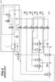
- a first example of an electro-pneumatic system 100 is claimed in patent EP3148853 , shown in FIG. 3 .
- the EPDA module corresponds to the electro-pneumatic emergency braking module 101
- the weighing control module corresponds to the emergency braking control module 103
- the EPCA modules each correspond to the electro-pneumatic service braking module 107
- the outputs of the EPCA modules toward brake cylinders BC1, ..., BCN each correspond to a service braking pressure 111, ..., 114
- the braking control units each correspond to the service braking control module 108
- the output pressure to the relay valve 4 corresponds to the emergency braking pressure 106
- the MBP pressure corresponds to the supply pressure 102.
- the outlet pressure to the relay valve 4 supplies power to an electro-valve group made up of solenoid valves 10, 12, 20 used to pilot a relay valve RV.
- a second example of an electro-pneumatic system 100 is claimed in patent EP2830918 , shown in FIG. 4 .
- the dashed box 401 corresponds to the electro-pneumatic emergency braking module 101
- the dashed box 402 corresponds to an electro-pneumatic service braking module 111
- the pneumatic signal 403 corresponds to the emergency braking pressure 106.
- the braking systems as previously described are developed in accordance with railway standards EN50126, EN50128, EN50129.
- the EN50126 standard defines the methodology for assigning SIL0/1/2/3/4 safety levels to the subsystems, based on the results of the Safety Analysis, while the EN50128 and EN50129 standards define the design criteria to be applied to the software and hardware components respectively according to the assigned SIL levels. Based on the application of the standards cited above, the following statements and concepts may be expressed:
- the emergency braking control module 103 being used to control the generation of the emergency braking pressure 106, must be developed according to an SIL safety level higher than the SIL safety level required for the development of the service braking control module 108.
- the emergency braking control module 103 is developed according to EN50128 and EN50129 SEL ⁇ 3, while the service braking control module 108 is developed according to EN50128 and EN50129 SEL ⁇ 2.
- a development according to EN50129 SIL ⁇ 3 requires said emergency braking control module 103 to be isolated and independent from said service braking control module 108.
- a drawback of the system described above is represented in that in the presence of a failure of the emergency braking control module 103, the emergency braking pressure 106 may assume a value lower than the actual value necessary for emergency braking and service braking requested after the failure of the emergency braking control module 103. In this case, the electro-pneumatic system 100 will no longer be able to provide the braking force currently requested.
- WO2019123198 describes a further braking control system for at least one railway vehicle.
- An object of the present invention is to provide an electro-pneumatic service braking control system, particularly for at least one railway vehicle, which even in the presence of a failure of an emergency braking control module is capable of providing the braking force currently requested.
- an electro-pneumatic service and emergency braking control system for at least one railway vehicle or one railway bogie, having the features defined in Claim 1.
- Preferred embodiments of the invention are defined in the dependent claims, the content of which is to be understood as an integral part of the present description.
- an electro-pneumatic service and emergency braking control system 200 is illustrated, for at least one railway vehicle or one railway bogie, according to the invention.
- This electro-pneumatic service and emergency braking control system 200 comprises an electro-pneumatic emergency braking module 201 powered by a supply pressure 202 and arranged to generate an emergency braking pressure 206 and a emergency braking control module 203 arranged to control the electro-pneumatic emergency braking module 201 by means of a first group of control and feedback signals 222, so as to generate the emergency braking pressure 206 according to at least one weight information 204 relating to the at least one railway vehicle or railway bogie to be braked.
- Further values may condition the calculation of the emergency pressure 206 such as, but not exclusively, the instantaneous speed value of the vehicle 230, and/or a pressure value 231 indicating an emergency pressure request value, and/or an electrodynamic braking efficiency value 232 provided by the traction systems.
- Group of control and feedback signals may mean the case wherein there is a control signal and a feedback signal, or the case wherein there are more control signals and/or more feedback signals, or even the case wherein there is also only a single signal that performs both the control and feedback functions.
- at least one control signal may be present, normally two, one to excite a charging valve and one to excite a discharging valve, and at least one feedback signal, that is a signal from a feedback sensor.
- the electro-pneumatic service and emergency braking control system 200 further comprises an electro-pneumatic service braking module 207, which receives the emergency braking pressure 206 and generates at least one service braking pressure 211, ..., 214, and a service braking control module 208 arranged to control the electro-pneumatic service braking module 207 when an interruption device 216 of the electro-pneumatic service and emergency braking control system 200 allows the connection of a second group of control and feedback signals 209 from the service braking control module 208 to the electro-pneumatic service braking module 207.
- the electro-pneumatic service braking module 207 may also receive the supply pressure 202.
- the service braking control module 208 controls the electro-pneumatic service braking module 207 by means of the second group of control and feedback signals 209 so as to generate the at least one service braking pressure 211, ..., 214 as a function of the at least one weight information 204 relating to the at least one railway vehicle or railway bogie to be braked and a service braking request 210. Further values may condition the calculation of the service braking pressure 211,..., 214 such as for example, but not exclusively, the instantaneous speed value of the vehicle 230, and/or an electrodynamic braking efficiency value 232 provided by the traction systems.
- the one or more service braking pressures 211,..., 214 have a value less than or equal to a maximum value corresponding to the current assumed value of the emergency braking pressure 206.
- the electro-pneumatic service braking module 207 propagates the value of the emergency braking pressure 206 to the at least one service braking pressure 211, ..., 214 when the interruption device 216 does not allow the connection of the second group of control and feedback signals 209 from the service braking control module 208 to the electro-pneumatic service braking module 207.
- the interruption device 216 allows the connection of the second group of control and feedback signals 209 from the service braking control module 208 to the electro-pneumatic service braking module 207 when an emergency braking request signaled by an emergency request signal 215 is absent.
- the interruption device 216 does not allow the connection of the second group of control and feedback signals 209 from the service braking control module 208 to the electro-pneumatic service braking module 207 when there is an emergency braking request signaled by the emergency braking request signal 215.
- the interruption device 216 may maintain a closed contact configuration in the absence of the emergency braking request from the emergency request signal 215, and maintain an open contact configuration in the presence of the emergency braking request from the emergency braking request signal 215.
- the electro-pneumatic service and emergency braking control system comprises a switching device 221 which allows the connection of the first group of control and feedback signals 222 from the emergency braking control module 203 to the electro-pneumatic emergency braking control module 201 when a monitoring device 223, which monitors the operating status of the emergency braking control module 203, determines the correct operation of the emergency braking control module 203.
- the switching device 221 allows the connection of a third group of control and feedback signals 220 from the service braking control module 208 to the electro-pneumatic emergency braking module 201 when the monitoring device 223 determines an incorrect operation of the emergency braking control module 203.
- the monitoring device 223 may be obtained by means of a software function, a hardware circuit, or by means of a combination of a software function and a hardware circuit.
- the monitoring device 223 may also be included directly in the emergency braking control module 203.
- the electro-pneumatic emergency braking module 201 is connected via a group of signals 205 to a common terminal of the switching device 221.
- the first group of control and feedback signals 222 is connected to a further terminal of the switching device 221, and the third group of control and feedback signals 220 is connected to a still further terminal of the switching device 221.
- the switching device 221 has an excitation operative state, in which the switching device 221 positions itself when powered. In this resting operative state, the connection of the first group of control and feedback signals 222 from the emergency braking control module 203 to the electro-pneumatic emergency braking module 201 is allowed.
- the switching device 221 has a resting state, wherein said switching device 221 positions itself when not powered, so as to allow the connection of the third group of control and feedback signals 220 from the service braking control module 208 to the electro-pneumatic emergency braking module 201.
- said switching device 221 connects the group of signals 205 to the third group of control and feedback signals 220 of the service braking control module 208, connected to the respective terminals of the switching device 221.
- said switching device 221 connects the group of signals 205 to the first group of control and feedback signals 222 of the emergency control module 203, connected to the respective terminals of the switching device 221.
- the switching device 221 may be composed of a multi-switching relay, or a multiplicity of semiconductor switches.
- the monitoring module 223 may generate a control signal 224 for the switching device 221.
- said monitoring module 223 detects a correct operation of the emergency braking control module
- said monitoring module 223 powers the control signal 224, bringing the switching device 221 to the excitation state, connecting the group of signals 205 to the emergency braking control module 203.
- said monitoring module 223 disconnects the control signal 224, bringing the switching device 221 to the resting state, connecting the group of signals 205 to the service braking control module 208.
- the emergency braking control module 203 As long as the emergency braking control module 203 is functioning properly, it is able to control the electro-pneumatic emergency braking module 201 to generate the emergency braking pressure 206.
- the monitoring module 223 When the monitoring module 223 detects a malfunction of the emergency braking control module 203, the monitoring module 223 passes the control of the electro-pneumatic emergency braking module 203 to the service braking control module 208. In this way, the service braking control module 208 may control the electro-pneumatic emergency braking module 201 to continue to correctly generate the emergency braking pressure 206.
- a first advantage offered by this solution is that, in the presence of a failure of the emergency braking control module 203, the electro-pneumatic service braking module 207 continues to receive a correct emergency pressure value 206, which allows it to correctly generate the service braking pressures 211, 214 up to their maximum requested value.
- a second advantage offered by the solution proposed by the present invention is represented in that, in the presence of a failure of the emergency braking control module 203, upon the arrival of an emergency braking request by the signal 215, the emergency braking pressure 206 will still be available and replicated on the service braking pressures 211, ..., 214 of the electro-pneumatic service braking module 207, with a safety level at least equal to the safety level of the service braking control module 208. In this case, it will be the responsibility of the railway operator to decide whether the safety level lower than that recommended by the regulations is acceptable to complete the daily service cycle of the vehicle before resorting to the replacement of the electropneumatic system 200.
Landscapes
- Engineering & Computer Science (AREA)
- Transportation (AREA)
- Mechanical Engineering (AREA)
- Physics & Mathematics (AREA)
- Fluid Mechanics (AREA)
- Braking Systems And Boosters (AREA)
- Electric Propulsion And Braking For Vehicles (AREA)
- Valves And Accessory Devices For Braking Systems (AREA)
- Regulating Braking Force (AREA)
- Safety Devices In Control Systems (AREA)
- Braking Arrangements (AREA)
Claims (6)
- Elektropneumatisches Betriebs- und Notbremssteuerungssystem (200) für mindestens ein Schienenfahrzeug oder ein Schienendrehgestell, mit:- einem elektropneumatischen Notbremsmodul (201), das durch einen Versorgungsdruck (202) mit Leistung versorgt wird und so eingerichtet ist, dass es einen Notbremsdruck (206) erzeugt;- einem Notbremssteuerungsmodul (203), das so eingerichtet ist, dass es das elektropneumatische Notbremsmodul (201) mittels einer ersten Gruppe von Steuerungs- und Rückkopplungssignalen (222) so steuert, dass der Notbremsdruck (206) als eine Funktion mindestens einer Gewichtsinformation (204) in Bezug auf das mindestens eine Schienenfahrzeug oder Schienendrehgestell, das zu bremsen ist, erzeugt wird;- einem elektropneumatischen Betriebsbremsmodul (207), das den Notbremsdruck (206) aufnimmt und so eingerichtet ist, dass es mindestens einen Betriebsbremsdruck (211, ..., 214) erzeugt; und- einem Betriebsbremssteuerungsmodul (208), das so eingerichtet ist, dass es das elektropneumatische Betriebsbremsmodul (207) steuert, wenn eine Unterbrechungsvorrichtung (216) des elektropneumatischen Betriebs- und Notbremssteuerungssystems (200) die Verbindung einer zweiten Gruppe von Steuerungs- und Rückkopplungssignalen (209) von dem Betriebsbremssteuerungsmodul (208) zu dem elektropneumatischen Betriebsbremsmodul (207) zulässt; welches Betriebsbremssteuerungsmodul (208) das elektropneumatische Betriebsbremsmodul (207) mittels der zweiten Gruppe von Steuerungs- und Rückkopplungssignalen (209) so steuert, dass der mindestens eine Betriebsbremsdruck (211, ..., 214) als eine Funktion der mindestens einen Gewichtsinformation (204) in Bezug auf das mindestens eine Schienenfahrzeug oder Schienendrehgestell, das zu bremsen ist, und eine Betriebsbremsanforderung (210) erzeugt wird;welche eine oder mehreren Betriebsbremsdrücke (211, ..., 214) einen Wert kleiner als oder gleich einem maximalen Wert, der dem gegenwärtigen Wert des Notbremsdrucks (206) entspricht, aufweisen;bei dem das elektropneumatische Betriebsbremsmodul (207) so eingerichtet ist, dass es den Wert des Notbremsdrucks (206) an den mindestens einen Betriebsbremsdruck (211, ..., 214) überträgt, wenn die Unterbrechungsvorrichtung (216) die Verbindung der zweiten Gruppe von Steuerungs- und Rückkopplungssignalen (209) von dem Betriebsbremssteuerungsmodul (208) zu dem elektropneumatischen Betriebsbremsmodul (207) nicht zulässt;welche Unterbrechungsvorrichtung (216) die Verbindung der zweiten Gruppe von Steuerungs- und Rückkopplungssignalen (209) von dem Betriebsbremssteuerungsmodul (208) zu dem elektropneumatischen Betriebsbremsmodul (207) zulässt, wenn eine Notbremsanforderung durch ein Notanforderungssignal (215) nicht vorliegt, und die Verbindung der zweiten Gruppe von Steuerungs- und Rückkopplungssignalen (209) von dem Betriebsbremssteuerungsmodul (208) zu dem elektropneumatischen Betriebsbremsmodul (207) nicht zulässt, wenn eine Notbremsanforderung durch das Notbremsanforderungssignal (215) vorliegt;welches elektropneumatische Betriebs- und Notbremssteuerungssystem (200) dadurch gekennzeichnet ist, dass es eine Schaltvorrichtung (221) aufweist, die so eingerichtet ist, dass sie die Verbindung der ersten Gruppe von Steuerungs- und Rückkopplungssignalen (222) von dem Notbremssteuerungsmodul (203) zu dem elektropneumatischen Notbremsmodul (201) zulässt, wenn eine Überwachungsvorrichtung (223), die so eingerichtet ist, dass sie den Betriebszustand des Notbremssteuerungsmoduls (203) überwacht, einen korrekten Betrieb des Notbremssteuerungsmoduls (203) bestimmt, und dass sie die Verbindung einer dritten Gruppe von Steuerungs- und Rückkopplungssignalen (220) von dem Betriebsbremssteuerungsmodul (208) zu dem elektropneumatischen Notbremsmodul (201) zulässt, wenn die Überwachungsvorrichtung (223) einen inkorrekten Betrieb des Notbremssteuerungsmoduls (203) bestimmt.
- System nach Anspruch 1, bei dem die Überwachungsvorrichtung (223) so eingerichtet ist, dass sie die Schaltvorrichtung (221) durch ein Steuerungssignal (224) mit Leistung versorgt, wenn sie einen korrekten Betrieb des Notbremssteuerungsmoduls (203) bestimmt, und so eingerichtet ist, dass sie die Leistungszufuhr zu der Schaltvorrichtung (221) durch das Steuerungssignal (224) unterbricht, wenn sie einen inkorrekten Betrieb des Notbremssteuerungsmoduls (203) bestimmt;
welche Schaltvorrichtung (221) aufweist:einen Anregungswirksamkeitszustand, bei dem die Schaltvorrichtung (221) so eingerichtet ist, dass sie sich selbst so positioniert, wenn sie mit Leistung versorgt wird, dass die Verbindung des ersten Steuerungs- und Rückkopplungssignals (222) von dem Notbremssteuerungsmodul (203) zu dem elektropneumatischen Notbremsmodul (201) zugelassen wird, undeinen Ruhewirksamkeitszustand, bei dem die Schaltvorrichtung (221) so eingerichtet ist, dass sie sich selbst so positioniert, wenn sie nicht mit Leistung versorgt wird, dass die Verbindung des dritten Steuerungs- und Rückkopplungssignals (220) von dem Betriebsbremssteuerungsmodul (208) zu dem elektropneumatischen Notbremsmodul (201) zugelassen wird. - System nach Anspruch 1 oder 2, bei dem die Unterbrechungsvorrichtung (216) so eingerichtet ist, dass sie eine geschlossene Kontaktkonfiguration bei dem Nichtvorliegen der Notbremsanforderung durch das Notanforderungssignal (215) beibehält, und dass sie eine offene Kontaktkonfiguration bei dem Vorliegen der Notbremsanforderung durch das Notbremsanforderungssignal (215) beibehält.
- System nach einem der vorhergehenden Ansprüche, bei dem das elektropneumatische Betriebsbremsmodul (207) auch so eingerichtet ist, dass es den Versorgungsdruck (202) aufnimmt.
- System nach einem der vorhergehenden Ansprüche, bei dem die Überwachungsvorrichtung (223) mittels einer Softwarefunktion, einer Hardwareschaltung oder mittels einer Kombination einer Softwarefunktion und einer Hardwareschaltung ausgebildet ist.
- System nach einem der vorhergehenden Ansprüche, bei dem die Überwachungsvorrichtung (223) in dem Notbremssteuerungsmodul (203) enthalten ist.
Applications Claiming Priority (2)
| Application Number | Priority Date | Filing Date | Title |
|---|---|---|---|
| IT102019000012480A IT201900012480A1 (it) | 2019-07-22 | 2019-07-22 | Sistema di controllo elettro-pneumatico della frenatura di servizio, per almeno un veicolo ferroviario |
| PCT/IB2020/056887 WO2021014374A1 (en) | 2019-07-22 | 2020-07-22 | Electro-pneumatic emergency and service braking control system, for at least one railway vehicle |
Publications (2)
| Publication Number | Publication Date |
|---|---|
| EP4003797A1 EP4003797A1 (de) | 2022-06-01 |
| EP4003797B1 true EP4003797B1 (de) | 2023-09-06 |
Family
ID=68582249
Family Applications (1)
| Application Number | Title | Priority Date | Filing Date |
|---|---|---|---|
| EP20754369.5A Active EP4003797B1 (de) | 2019-07-22 | 2020-07-22 | Elektropneumatisches not- und betriebsbremssteuersystem für mindestens ein schienenfahrzeug |
Country Status (10)
| Country | Link |
|---|---|
| US (1) | US11981301B2 (de) |
| EP (1) | EP4003797B1 (de) |
| JP (1) | JP7558245B2 (de) |
| KR (1) | KR102647666B1 (de) |
| CN (1) | CN114174132B (de) |
| BR (1) | BR112022001166A2 (de) |
| ES (1) | ES2964153T3 (de) |
| HU (1) | HUE064004T2 (de) |
| IT (1) | IT201900012480A1 (de) |
| WO (1) | WO2021014374A1 (de) |
Cited By (1)
| Publication number | Priority date | Publication date | Assignee | Title |
|---|---|---|---|---|
| US20230083980A1 (en) * | 2020-02-13 | 2023-03-16 | Faiveley Transport Italia S.P.A. | Monitoring device of the open or closed state of an electric line of a railway vehicle, and electric line of a railway vehicle |
Families Citing this family (2)
| Publication number | Priority date | Publication date | Assignee | Title |
|---|---|---|---|---|
| DE102022203763A1 (de) * | 2022-04-13 | 2023-10-19 | Knorr-Bremse Systeme für Schienenfahrzeuge GmbH | Bremssystem und Bremsverfahren für Schienenfahrzeuge |
| DE102023209050A1 (de) * | 2023-09-18 | 2025-03-20 | Knorr-Bremse Systeme für Schienenfahrzeuge GmbH | Funktionseinheit mit Rückfallbetriebsmodus für ein Betriebssystem eines Schienenfahrzeugs |
Family Cites Families (14)
| Publication number | Priority date | Publication date | Assignee | Title |
|---|---|---|---|---|
| US5662391A (en) * | 1996-01-16 | 1997-09-02 | Westinghouse Air Brake Company | Pneumatic empty/load proportioning for electro-pneumatic brake |
| US5934765A (en) * | 1996-12-19 | 1999-08-10 | Westinghouse Air Brake Company | Electro-pneumatic brake system and controller therefor |
| ATE374138T1 (de) * | 1998-10-23 | 2007-10-15 | Knorr Bremse Systeme | Bremssystem für ein schienenfahrzeug |
| GB2359600A (en) * | 2000-02-25 | 2001-08-29 | Westinghouse Brake & Signal | Controlling a pneumatic brake system |
| US6631873B2 (en) * | 2000-05-12 | 2003-10-14 | Glen T. Fisher | Protection device to prevent train incursions into a forbidden area |
| GB2502252B (en) * | 2012-03-26 | 2018-09-05 | Knorr Bremse Rail Systems Uk Ltd | Emergency braking |
| KR101306133B1 (ko) * | 2012-04-17 | 2013-09-09 | 주식회사 대동 | 차량의 비상등 점멸 스위치 장치 및 그 제어방법 |
| ES2676830T3 (es) * | 2014-05-28 | 2018-07-25 | Faiveley Transport Italia S.P.A. | Sistema de frenado electro-neumático para un vehículo de ferrocarril |
| US11498541B2 (en) * | 2015-11-12 | 2022-11-15 | Faiveley Transport Italia S.P.A. | Vehicle braking assembly |
| IT201700040680A1 (it) * | 2017-04-12 | 2018-10-12 | Faiveley Transport Italia Spa | Sistema di controllo elettronico della frenatura di emergenza e di servizio, per un veicolo ferroviario. |
| DE102017120691A1 (de) * | 2017-09-07 | 2019-03-07 | Knorr-Bremse Systeme für Nutzfahrzeuge GmbH | Elektropneumatische Parkbremssteuereinrichtung |
| CN107963071B (zh) * | 2017-11-29 | 2019-08-20 | 中车青岛四方车辆研究所有限公司 | 轨道车辆制动控制装置 |
| ES2911573T3 (es) * | 2017-12-18 | 2022-05-19 | Faiveley Transport Italia Spa | Sistema de control de frenado de emergencia y de servicio para al menos un vehículo ferroviario |
| CN108177639B (zh) * | 2018-01-11 | 2019-10-15 | 威马智慧出行科技(上海)有限公司 | 用于电动汽车的紧急制动系统及方法和电动汽车 |
-
2019
- 2019-07-22 IT IT102019000012480A patent/IT201900012480A1/it unknown
-
2020
- 2020-07-22 JP JP2022503994A patent/JP7558245B2/ja active Active
- 2020-07-22 CN CN202080053280.6A patent/CN114174132B/zh active Active
- 2020-07-22 US US17/597,762 patent/US11981301B2/en active Active
- 2020-07-22 KR KR1020227005901A patent/KR102647666B1/ko active Active
- 2020-07-22 WO PCT/IB2020/056887 patent/WO2021014374A1/en not_active Ceased
- 2020-07-22 HU HUE20754369A patent/HUE064004T2/hu unknown
- 2020-07-22 ES ES20754369T patent/ES2964153T3/es active Active
- 2020-07-22 BR BR112022001166A patent/BR112022001166A2/pt unknown
- 2020-07-22 EP EP20754369.5A patent/EP4003797B1/de active Active
Cited By (2)
| Publication number | Priority date | Publication date | Assignee | Title |
|---|---|---|---|---|
| US20230083980A1 (en) * | 2020-02-13 | 2023-03-16 | Faiveley Transport Italia S.P.A. | Monitoring device of the open or closed state of an electric line of a railway vehicle, and electric line of a railway vehicle |
| US12570264B2 (en) * | 2020-02-13 | 2026-03-10 | Faiveley Transport Italia S.P.A. | Monitoring device of the open or closed state of an electric line of a railway vehicle, and electric line of a railway vehicle |
Also Published As
| Publication number | Publication date |
|---|---|
| KR20220061101A (ko) | 2022-05-12 |
| US20220258709A1 (en) | 2022-08-18 |
| IT201900012480A1 (it) | 2021-01-22 |
| JP7558245B2 (ja) | 2024-09-30 |
| CN114174132A (zh) | 2022-03-11 |
| CN114174132B (zh) | 2023-06-30 |
| ES2964153T3 (es) | 2024-04-04 |
| US11981301B2 (en) | 2024-05-14 |
| KR102647666B1 (ko) | 2024-03-14 |
| EP4003797A1 (de) | 2022-06-01 |
| WO2021014374A1 (en) | 2021-01-28 |
| JP2022541595A (ja) | 2022-09-26 |
| HUE064004T2 (hu) | 2024-02-28 |
| BR112022001166A2 (pt) | 2022-03-15 |
Similar Documents
| Publication | Publication Date | Title |
|---|---|---|
| EP4003797B1 (de) | Elektropneumatisches not- und betriebsbremssteuersystem für mindestens ein schienenfahrzeug | |
| RU2762606C2 (ru) | Электронная система управления аварийным и служебным торможением для железнодорожного транспорта | |
| EP1531109B1 (de) | Elektronische Regeleinheit für eine Lokomotive | |
| US6435623B1 (en) | Valve assembly for electrically controlled pneumatic brakes | |
| EP1583677B1 (de) | Schnittstellensystem von druckluftgesteuerten zu elektrogesteuerten druckluftbremssystemen | |
| EP3784539B1 (de) | Elektronisch-pneumatisches steuerungssystem für not- und betriebsbremsung, insbesondere für mindestens ein schienenfahrzeug | |
| US5332297A (en) | Charging cut-off valve arrangement for microprocessor-based electropneumatic locomotive brake control system | |
| US11851040B2 (en) | Electronic control system of the braking of a railway vehicle | |
| AU2010297446A1 (en) | Brake system having smart actuator for braking a rail-guided vehicle | |
| WO2004054839A9 (en) | Interface system from pneumatic to electrically-controlled pneumatic brake systems | |
| US6347840B1 (en) | ECP commanded emergencies via a conventional EAB brake controller | |
| CA2359238C (en) | Method of braking in an integrated train propulsion and brake system | |
| US20250153691A1 (en) | Brake system for a rail vehicle, and method for controlling such a brake system | |
| AU750378B2 (en) | Integrated train electrical and pneumatic brakes | |
| US5803554A (en) | Brake monitoring device for railroad cars | |
| CN116901920A (zh) | 一种商用车线控冗余制动单元及其控制方法 | |
| US20260070530A1 (en) | Redundant Brake System for Highly Automated Vehicles | |
| EA042326B1 (ru) | Электропневматическая система управления экстренным и рабочим торможением для по меньшей мере одного железнодорожного транспортного средства | |
| CN114599560A (zh) | 用于车辆的电制动系统 | |
| KR102953500B1 (ko) | 브레이크 시스템 및 그 제어방법 | |
| JPH0958450A (ja) | 電気車用空気ブレーキ装置 |
Legal Events
| Date | Code | Title | Description |
|---|---|---|---|
| STAA | Information on the status of an ep patent application or granted ep patent |
Free format text: STATUS: UNKNOWN |
|
| STAA | Information on the status of an ep patent application or granted ep patent |
Free format text: STATUS: THE INTERNATIONAL PUBLICATION HAS BEEN MADE |
|
| PUAI | Public reference made under article 153(3) epc to a published international application that has entered the european phase |
Free format text: ORIGINAL CODE: 0009012 |
|
| STAA | Information on the status of an ep patent application or granted ep patent |
Free format text: STATUS: REQUEST FOR EXAMINATION WAS MADE |
|
| 17P | Request for examination filed |
Effective date: 20220217 |
|
| AK | Designated contracting states |
Kind code of ref document: A1 Designated state(s): AL AT BE BG CH CY CZ DE DK EE ES FI FR GB GR HR HU IE IS IT LI LT LU LV MC MK MT NL NO PL PT RO RS SE SI SK SM TR |
|
| DAV | Request for validation of the european patent (deleted) | ||
| DAX | Request for extension of the european patent (deleted) | ||
| GRAP | Despatch of communication of intention to grant a patent |
Free format text: ORIGINAL CODE: EPIDOSNIGR1 |
|
| STAA | Information on the status of an ep patent application or granted ep patent |
Free format text: STATUS: GRANT OF PATENT IS INTENDED |
|
| INTG | Intention to grant announced |
Effective date: 20230327 |
|
| GRAS | Grant fee paid |
Free format text: ORIGINAL CODE: EPIDOSNIGR3 |
|
| P01 | Opt-out of the competence of the unified patent court (upc) registered |
Effective date: 20230530 |
|
| GRAA | (expected) grant |
Free format text: ORIGINAL CODE: 0009210 |
|
| STAA | Information on the status of an ep patent application or granted ep patent |
Free format text: STATUS: THE PATENT HAS BEEN GRANTED |
|
| AK | Designated contracting states |
Kind code of ref document: B1 Designated state(s): AL AT BE BG CH CY CZ DE DK EE ES FI FR GB GR HR HU IE IS IT LI LT LU LV MC MK MT NL NO PL PT RO RS SE SI SK SM TR |
|
| REG | Reference to a national code |
Ref country code: GB Ref legal event code: FG4D |
|
| REG | Reference to a national code |
Ref country code: CH Ref legal event code: EP |
|
| REG | Reference to a national code |
Ref country code: IE Ref legal event code: FG4D |
|
| REG | Reference to a national code |
Ref country code: DE Ref legal event code: R096 Ref document number: 602020017318 Country of ref document: DE |
|
| REG | Reference to a national code |
Ref country code: LT Ref legal event code: MG9D |
|
| REG | Reference to a national code |
Ref country code: NL Ref legal event code: MP Effective date: 20230906 |
|
| PG25 | Lapsed in a contracting state [announced via postgrant information from national office to epo] |
Ref country code: GR Free format text: LAPSE BECAUSE OF FAILURE TO SUBMIT A TRANSLATION OF THE DESCRIPTION OR TO PAY THE FEE WITHIN THE PRESCRIBED TIME-LIMIT Effective date: 20231207 |
|
| PG25 | Lapsed in a contracting state [announced via postgrant information from national office to epo] |
Ref country code: SE Free format text: LAPSE BECAUSE OF FAILURE TO SUBMIT A TRANSLATION OF THE DESCRIPTION OR TO PAY THE FEE WITHIN THE PRESCRIBED TIME-LIMIT Effective date: 20230906 Ref country code: RS Free format text: LAPSE BECAUSE OF FAILURE TO SUBMIT A TRANSLATION OF THE DESCRIPTION OR TO PAY THE FEE WITHIN THE PRESCRIBED TIME-LIMIT Effective date: 20230906 Ref country code: NO Free format text: LAPSE BECAUSE OF FAILURE TO SUBMIT A TRANSLATION OF THE DESCRIPTION OR TO PAY THE FEE WITHIN THE PRESCRIBED TIME-LIMIT Effective date: 20231206 Ref country code: LV Free format text: LAPSE BECAUSE OF FAILURE TO SUBMIT A TRANSLATION OF THE DESCRIPTION OR TO PAY THE FEE WITHIN THE PRESCRIBED TIME-LIMIT Effective date: 20230906 Ref country code: LT Free format text: LAPSE BECAUSE OF FAILURE TO SUBMIT A TRANSLATION OF THE DESCRIPTION OR TO PAY THE FEE WITHIN THE PRESCRIBED TIME-LIMIT Effective date: 20230906 Ref country code: HR Free format text: LAPSE BECAUSE OF FAILURE TO SUBMIT A TRANSLATION OF THE DESCRIPTION OR TO PAY THE FEE WITHIN THE PRESCRIBED TIME-LIMIT Effective date: 20230906 Ref country code: GR Free format text: LAPSE BECAUSE OF FAILURE TO SUBMIT A TRANSLATION OF THE DESCRIPTION OR TO PAY THE FEE WITHIN THE PRESCRIBED TIME-LIMIT Effective date: 20231207 Ref country code: FI Free format text: LAPSE BECAUSE OF FAILURE TO SUBMIT A TRANSLATION OF THE DESCRIPTION OR TO PAY THE FEE WITHIN THE PRESCRIBED TIME-LIMIT Effective date: 20230906 |
|
| REG | Reference to a national code |
Ref country code: AT Ref legal event code: MK05 Ref document number: 1608160 Country of ref document: AT Kind code of ref document: T Effective date: 20230906 |
|
| REG | Reference to a national code |
Ref country code: HU Ref legal event code: AG4A Ref document number: E064004 Country of ref document: HU |
|
| PG25 | Lapsed in a contracting state [announced via postgrant information from national office to epo] |
Ref country code: NL Free format text: LAPSE BECAUSE OF FAILURE TO SUBMIT A TRANSLATION OF THE DESCRIPTION OR TO PAY THE FEE WITHIN THE PRESCRIBED TIME-LIMIT Effective date: 20230906 |
|
| REG | Reference to a national code |
Ref country code: ES Ref legal event code: FG2A Ref document number: 2964153 Country of ref document: ES Kind code of ref document: T3 Effective date: 20240404 |
|
| PG25 | Lapsed in a contracting state [announced via postgrant information from national office to epo] |
Ref country code: IS Free format text: LAPSE BECAUSE OF FAILURE TO SUBMIT A TRANSLATION OF THE DESCRIPTION OR TO PAY THE FEE WITHIN THE PRESCRIBED TIME-LIMIT Effective date: 20240106 |
|
| PG25 | Lapsed in a contracting state [announced via postgrant information from national office to epo] |
Ref country code: AT Free format text: LAPSE BECAUSE OF FAILURE TO SUBMIT A TRANSLATION OF THE DESCRIPTION OR TO PAY THE FEE WITHIN THE PRESCRIBED TIME-LIMIT Effective date: 20230906 |
|
| PG25 | Lapsed in a contracting state [announced via postgrant information from national office to epo] |
Ref country code: SM Free format text: LAPSE BECAUSE OF FAILURE TO SUBMIT A TRANSLATION OF THE DESCRIPTION OR TO PAY THE FEE WITHIN THE PRESCRIBED TIME-LIMIT Effective date: 20230906 Ref country code: RO Free format text: LAPSE BECAUSE OF FAILURE TO SUBMIT A TRANSLATION OF THE DESCRIPTION OR TO PAY THE FEE WITHIN THE PRESCRIBED TIME-LIMIT Effective date: 20230906 Ref country code: IS Free format text: LAPSE BECAUSE OF FAILURE TO SUBMIT A TRANSLATION OF THE DESCRIPTION OR TO PAY THE FEE WITHIN THE PRESCRIBED TIME-LIMIT Effective date: 20240106 Ref country code: EE Free format text: LAPSE BECAUSE OF FAILURE TO SUBMIT A TRANSLATION OF THE DESCRIPTION OR TO PAY THE FEE WITHIN THE PRESCRIBED TIME-LIMIT Effective date: 20230906 Ref country code: CZ Free format text: LAPSE BECAUSE OF FAILURE TO SUBMIT A TRANSLATION OF THE DESCRIPTION OR TO PAY THE FEE WITHIN THE PRESCRIBED TIME-LIMIT Effective date: 20230906 Ref country code: AT Free format text: LAPSE BECAUSE OF FAILURE TO SUBMIT A TRANSLATION OF THE DESCRIPTION OR TO PAY THE FEE WITHIN THE PRESCRIBED TIME-LIMIT Effective date: 20230906 Ref country code: SK Free format text: LAPSE BECAUSE OF FAILURE TO SUBMIT A TRANSLATION OF THE DESCRIPTION OR TO PAY THE FEE WITHIN THE PRESCRIBED TIME-LIMIT Effective date: 20230906 Ref country code: PT Free format text: LAPSE BECAUSE OF FAILURE TO SUBMIT A TRANSLATION OF THE DESCRIPTION OR TO PAY THE FEE WITHIN THE PRESCRIBED TIME-LIMIT Effective date: 20240108 |
|
| PG25 | Lapsed in a contracting state [announced via postgrant information from national office to epo] |
Ref country code: PL Free format text: LAPSE BECAUSE OF FAILURE TO SUBMIT A TRANSLATION OF THE DESCRIPTION OR TO PAY THE FEE WITHIN THE PRESCRIBED TIME-LIMIT Effective date: 20230906 |
|
| REG | Reference to a national code |
Ref country code: DE Ref legal event code: R097 Ref document number: 602020017318 Country of ref document: DE |
|
| PG25 | Lapsed in a contracting state [announced via postgrant information from national office to epo] |
Ref country code: DK Free format text: LAPSE BECAUSE OF FAILURE TO SUBMIT A TRANSLATION OF THE DESCRIPTION OR TO PAY THE FEE WITHIN THE PRESCRIBED TIME-LIMIT Effective date: 20230906 |
|
| PLBE | No opposition filed within time limit |
Free format text: ORIGINAL CODE: 0009261 |
|
| STAA | Information on the status of an ep patent application or granted ep patent |
Free format text: STATUS: NO OPPOSITION FILED WITHIN TIME LIMIT |
|
| PG25 | Lapsed in a contracting state [announced via postgrant information from national office to epo] |
Ref country code: DK Free format text: LAPSE BECAUSE OF FAILURE TO SUBMIT A TRANSLATION OF THE DESCRIPTION OR TO PAY THE FEE WITHIN THE PRESCRIBED TIME-LIMIT Effective date: 20230906 Ref country code: SI Free format text: LAPSE BECAUSE OF FAILURE TO SUBMIT A TRANSLATION OF THE DESCRIPTION OR TO PAY THE FEE WITHIN THE PRESCRIBED TIME-LIMIT Effective date: 20230906 |
|
| 26N | No opposition filed |
Effective date: 20240607 |
|
| PG25 | Lapsed in a contracting state [announced via postgrant information from national office to epo] |
Ref country code: BG Free format text: LAPSE BECAUSE OF FAILURE TO SUBMIT A TRANSLATION OF THE DESCRIPTION OR TO PAY THE FEE WITHIN THE PRESCRIBED TIME-LIMIT Effective date: 20230906 |
|
| PG25 | Lapsed in a contracting state [announced via postgrant information from national office to epo] |
Ref country code: BG Free format text: LAPSE BECAUSE OF FAILURE TO SUBMIT A TRANSLATION OF THE DESCRIPTION OR TO PAY THE FEE WITHIN THE PRESCRIBED TIME-LIMIT Effective date: 20230906 |
|
| PG25 | Lapsed in a contracting state [announced via postgrant information from national office to epo] |
Ref country code: MC Free format text: LAPSE BECAUSE OF FAILURE TO SUBMIT A TRANSLATION OF THE DESCRIPTION OR TO PAY THE FEE WITHIN THE PRESCRIBED TIME-LIMIT Effective date: 20230906 |
|
| REG | Reference to a national code |
Ref country code: CH Ref legal event code: PL |
|
| PG25 | Lapsed in a contracting state [announced via postgrant information from national office to epo] |
Ref country code: LU Free format text: LAPSE BECAUSE OF NON-PAYMENT OF DUE FEES Effective date: 20240722 |
|
| PG25 | Lapsed in a contracting state [announced via postgrant information from national office to epo] |
Ref country code: LU Free format text: LAPSE BECAUSE OF NON-PAYMENT OF DUE FEES Effective date: 20240722 |
|
| PG25 | Lapsed in a contracting state [announced via postgrant information from national office to epo] |
Ref country code: BE Free format text: LAPSE BECAUSE OF NON-PAYMENT OF DUE FEES Effective date: 20240731 Ref country code: CH Free format text: LAPSE BECAUSE OF NON-PAYMENT OF DUE FEES Effective date: 20240731 |
|
| REG | Reference to a national code |
Ref country code: BE Ref legal event code: MM Effective date: 20240731 |
|
| PG25 | Lapsed in a contracting state [announced via postgrant information from national office to epo] |
Ref country code: IE Free format text: LAPSE BECAUSE OF NON-PAYMENT OF DUE FEES Effective date: 20240722 |
|
| PGFP | Annual fee paid to national office [announced via postgrant information from national office to epo] |
Ref country code: HU Payment date: 20250630 Year of fee payment: 6 |
|
| PGFP | Annual fee paid to national office [announced via postgrant information from national office to epo] |
Ref country code: ES Payment date: 20250822 Year of fee payment: 6 |
|
| PGFP | Annual fee paid to national office [announced via postgrant information from national office to epo] |
Ref country code: DE Payment date: 20250618 Year of fee payment: 6 |
|
| PGFP | Annual fee paid to national office [announced via postgrant information from national office to epo] |
Ref country code: IT Payment date: 20250618 Year of fee payment: 6 |
|
| PGFP | Annual fee paid to national office [announced via postgrant information from national office to epo] |
Ref country code: GB Payment date: 20250717 Year of fee payment: 6 |
|
| PGFP | Annual fee paid to national office [announced via postgrant information from national office to epo] |
Ref country code: FR Payment date: 20250722 Year of fee payment: 6 |
|
| PG25 | Lapsed in a contracting state [announced via postgrant information from national office to epo] |
Ref country code: CY Free format text: LAPSE BECAUSE OF FAILURE TO SUBMIT A TRANSLATION OF THE DESCRIPTION OR TO PAY THE FEE WITHIN THE PRESCRIBED TIME-LIMIT; INVALID AB INITIO Effective date: 20200722 |