EP4003761B1 - Tyre comprising a tread - Google Patents
Tyre comprising a tread Download PDFInfo
- Publication number
- EP4003761B1 EP4003761B1 EP20757643.0A EP20757643A EP4003761B1 EP 4003761 B1 EP4003761 B1 EP 4003761B1 EP 20757643 A EP20757643 A EP 20757643A EP 4003761 B1 EP4003761 B1 EP 4003761B1
- Authority
- EP
- European Patent Office
- Prior art keywords
- tread
- block
- incision
- pattern
- cutout
- Prior art date
- Legal status (The legal status is an assumption and is not a legal conclusion. Google has not performed a legal analysis and makes no representation as to the accuracy of the status listed.)
- Active
Links
- 229920001971 elastomer Polymers 0.000 claims description 36
- 229920003244 diene elastomer Polymers 0.000 claims description 28
- 239000000806 elastomer Substances 0.000 claims description 24
- XUIMIQQOPSSXEZ-UHFFFAOYSA-N Silicon Chemical group [Si] XUIMIQQOPSSXEZ-UHFFFAOYSA-N 0.000 claims description 18
- 239000000463 material Substances 0.000 claims description 18
- 239000000203 mixture Substances 0.000 claims description 18
- 229910052710 silicon Inorganic materials 0.000 claims description 18
- 125000005372 silanol group Chemical group 0.000 claims description 16
- 125000000524 functional group Chemical group 0.000 claims description 15
- 229910052757 nitrogen Inorganic materials 0.000 claims description 7
- KAKZBPTYRLMSJV-UHFFFAOYSA-N butadiene group Chemical group C=CC=C KAKZBPTYRLMSJV-UHFFFAOYSA-N 0.000 claims description 6
- 230000009477 glass transition Effects 0.000 claims description 6
- 125000004433 nitrogen atom Chemical group N* 0.000 claims description 6
- 239000004215 Carbon black (E152) Substances 0.000 claims description 5
- 229920001577 copolymer Polymers 0.000 claims description 5
- 229930195733 hydrocarbon Natural products 0.000 claims description 5
- 150000001875 compounds Chemical class 0.000 claims description 4
- SCPYDCQAZCOKTP-UHFFFAOYSA-N silanol Chemical compound [SiH3]O SCPYDCQAZCOKTP-UHFFFAOYSA-N 0.000 claims description 4
- 150000003512 tertiary amines Chemical class 0.000 claims description 4
- PPBRXRYQALVLMV-UHFFFAOYSA-N Styrene Natural products C=CC1=CC=CC=C1 PPBRXRYQALVLMV-UHFFFAOYSA-N 0.000 claims description 3
- 125000001931 aliphatic group Chemical group 0.000 claims description 2
- 125000001664 diethylamino group Chemical group [H]C([H])([H])C([H])([H])N(*)C([H])([H])C([H])([H])[H] 0.000 claims description 2
- 125000002147 dimethylamino group Chemical group [H]C([H])([H])N(*)C([H])([H])[H] 0.000 claims description 2
- CWAFVXWRGIEBPL-UHFFFAOYSA-N ethoxysilane Chemical compound CCO[SiH3] CWAFVXWRGIEBPL-UHFFFAOYSA-N 0.000 claims description 2
- ARYZCSRUUPFYMY-UHFFFAOYSA-N methoxysilane Chemical compound CO[SiH3] ARYZCSRUUPFYMY-UHFFFAOYSA-N 0.000 claims description 2
- 125000006850 spacer group Chemical group 0.000 claims description 2
- 150000002430 hydrocarbons Chemical class 0.000 claims 2
- 239000011295 pitch Substances 0.000 description 50
- 150000001412 amines Chemical group 0.000 description 14
- 238000009432 framing Methods 0.000 description 9
- XLYOFNOQVPJJNP-UHFFFAOYSA-N water Substances O XLYOFNOQVPJJNP-UHFFFAOYSA-N 0.000 description 8
- -1 hydrocarbon radical Chemical class 0.000 description 7
- 238000000034 method Methods 0.000 description 6
- 238000005096 rolling process Methods 0.000 description 6
- 238000006460 hydrolysis reaction Methods 0.000 description 5
- VYPSYNLAJGMNEJ-UHFFFAOYSA-N Silicium dioxide Chemical compound O=[Si]=O VYPSYNLAJGMNEJ-UHFFFAOYSA-N 0.000 description 4
- 239000000178 monomer Substances 0.000 description 4
- 125000003545 alkoxy group Chemical group 0.000 description 3
- 125000004429 atom Chemical group 0.000 description 3
- 230000007062 hydrolysis Effects 0.000 description 3
- JCXJVPUVTGWSNB-UHFFFAOYSA-N Nitrogen dioxide Chemical compound O=[N]=O JCXJVPUVTGWSNB-UHFFFAOYSA-N 0.000 description 2
- 239000011324 bead Substances 0.000 description 2
- 239000011203 carbon fibre reinforced carbon Substances 0.000 description 2
- 125000004122 cyclic group Chemical group 0.000 description 2
- 150000001993 dienes Chemical class 0.000 description 2
- 229920001519 homopolymer Polymers 0.000 description 2
- 125000002887 hydroxy group Chemical group [H]O* 0.000 description 2
- 230000000977 initiatory effect Effects 0.000 description 2
- 230000004048 modification Effects 0.000 description 2
- 238000012986 modification Methods 0.000 description 2
- 238000006116 polymerization reaction Methods 0.000 description 2
- 150000003254 radicals Chemical class 0.000 description 2
- 239000000377 silicon dioxide Substances 0.000 description 2
- 239000000126 substance Substances 0.000 description 2
- 239000013032 Hydrocarbon resin Substances 0.000 description 1
- BLRPTPMANUNPDV-UHFFFAOYSA-N Silane Chemical group [SiH4] BLRPTPMANUNPDV-UHFFFAOYSA-N 0.000 description 1
- ATJFFYVFTNAWJD-UHFFFAOYSA-N Tin Chemical compound [Sn] ATJFFYVFTNAWJD-UHFFFAOYSA-N 0.000 description 1
- 230000001154 acute effect Effects 0.000 description 1
- 230000003542 behavioural effect Effects 0.000 description 1
- 150000007942 carboxylates Chemical class 0.000 description 1
- 238000006243 chemical reaction Methods 0.000 description 1
- 239000003795 chemical substances by application Substances 0.000 description 1
- 239000007822 coupling agent Substances 0.000 description 1
- 125000004093 cyano group Chemical group *C#N 0.000 description 1
- 230000005489 elastic deformation Effects 0.000 description 1
- 229940082150 encore Drugs 0.000 description 1
- 150000002118 epoxides Chemical class 0.000 description 1
- 125000005842 heteroatom Chemical group 0.000 description 1
- 229920006270 hydrocarbon resin Polymers 0.000 description 1
- 238000006459 hydrosilylation reaction Methods 0.000 description 1
- 150000002466 imines Chemical class 0.000 description 1
- 239000003999 initiator Substances 0.000 description 1
- 239000012948 isocyanate Substances 0.000 description 1
- 150000002513 isocyanates Chemical class 0.000 description 1
- 239000007788 liquid Substances 0.000 description 1
- 239000011159 matrix material Substances 0.000 description 1
- 238000005259 measurement Methods 0.000 description 1
- 229910052760 oxygen Inorganic materials 0.000 description 1
- 150000003003 phosphines Chemical group 0.000 description 1
- 239000004014 plasticizer Substances 0.000 description 1
- 229920002587 poly(1,3-butadiene) polymer Polymers 0.000 description 1
- 229920001296 polysiloxane Polymers 0.000 description 1
- 150000003141 primary amines Chemical class 0.000 description 1
- 230000008569 process Effects 0.000 description 1
- 125000002572 propoxy group Chemical group [*]OC([H])([H])C(C([H])([H])[H])([H])[H] 0.000 description 1
- 229920005989 resin Polymers 0.000 description 1
- 239000011347 resin Substances 0.000 description 1
- 230000004044 response Effects 0.000 description 1
- 150000003335 secondary amines Chemical class 0.000 description 1
- 238000010008 shearing Methods 0.000 description 1
- 229910000077 silane Inorganic materials 0.000 description 1
- 239000010703 silicon Substances 0.000 description 1
- 229910052717 sulfur Inorganic materials 0.000 description 1
- 229920005992 thermoplastic resin Polymers 0.000 description 1
- 150000003573 thiols Chemical class 0.000 description 1
Images


Classifications
-
- B—PERFORMING OPERATIONS; TRANSPORTING
- B60—VEHICLES IN GENERAL
- B60C—VEHICLE TYRES; TYRE INFLATION; TYRE CHANGING; CONNECTING VALVES TO INFLATABLE ELASTIC BODIES IN GENERAL; DEVICES OR ARRANGEMENTS RELATED TO TYRES
- B60C11/00—Tyre tread bands; Tread patterns; Anti-skid inserts
- B60C11/03—Tread patterns
- B60C11/0302—Tread patterns directional pattern, i.e. with main rolling direction
-
- B—PERFORMING OPERATIONS; TRANSPORTING
- B60—VEHICLES IN GENERAL
- B60C—VEHICLE TYRES; TYRE INFLATION; TYRE CHANGING; CONNECTING VALVES TO INFLATABLE ELASTIC BODIES IN GENERAL; DEVICES OR ARRANGEMENTS RELATED TO TYRES
- B60C1/00—Tyres characterised by the chemical composition or the physical arrangement or mixture of the composition
- B60C1/0016—Compositions of the tread
-
- B—PERFORMING OPERATIONS; TRANSPORTING
- B60—VEHICLES IN GENERAL
- B60C—VEHICLE TYRES; TYRE INFLATION; TYRE CHANGING; CONNECTING VALVES TO INFLATABLE ELASTIC BODIES IN GENERAL; DEVICES OR ARRANGEMENTS RELATED TO TYRES
- B60C11/00—Tyre tread bands; Tread patterns; Anti-skid inserts
- B60C11/03—Tread patterns
- B60C11/0318—Tread patterns irregular patterns with particular pitch sequence
-
- B—PERFORMING OPERATIONS; TRANSPORTING
- B60—VEHICLES IN GENERAL
- B60C—VEHICLE TYRES; TYRE INFLATION; TYRE CHANGING; CONNECTING VALVES TO INFLATABLE ELASTIC BODIES IN GENERAL; DEVICES OR ARRANGEMENTS RELATED TO TYRES
- B60C11/00—Tyre tread bands; Tread patterns; Anti-skid inserts
- B60C11/03—Tread patterns
- B60C11/12—Tread patterns characterised by the use of narrow slits or incisions, e.g. sipes
-
- C—CHEMISTRY; METALLURGY
- C08—ORGANIC MACROMOLECULAR COMPOUNDS; THEIR PREPARATION OR CHEMICAL WORKING-UP; COMPOSITIONS BASED THEREON
- C08K—Use of inorganic or non-macromolecular organic substances as compounding ingredients
- C08K3/00—Use of inorganic substances as compounding ingredients
- C08K3/34—Silicon-containing compounds
- C08K3/36—Silica
-
- C—CHEMISTRY; METALLURGY
- C08—ORGANIC MACROMOLECULAR COMPOUNDS; THEIR PREPARATION OR CHEMICAL WORKING-UP; COMPOSITIONS BASED THEREON
- C08L—COMPOSITIONS OF MACROMOLECULAR COMPOUNDS
- C08L15/00—Compositions of rubber derivatives
-
- C—CHEMISTRY; METALLURGY
- C08—ORGANIC MACROMOLECULAR COMPOUNDS; THEIR PREPARATION OR CHEMICAL WORKING-UP; COMPOSITIONS BASED THEREON
- C08L—COMPOSITIONS OF MACROMOLECULAR COMPOUNDS
- C08L57/00—Compositions of unspecified polymers obtained by reactions only involving carbon-to-carbon unsaturated bonds
- C08L57/02—Copolymers of mineral oil hydrocarbons
-
- C—CHEMISTRY; METALLURGY
- C08—ORGANIC MACROMOLECULAR COMPOUNDS; THEIR PREPARATION OR CHEMICAL WORKING-UP; COMPOSITIONS BASED THEREON
- C08L—COMPOSITIONS OF MACROMOLECULAR COMPOUNDS
- C08L9/00—Compositions of homopolymers or copolymers of conjugated diene hydrocarbons
- C08L9/06—Copolymers with styrene
-
- C—CHEMISTRY; METALLURGY
- C08—ORGANIC MACROMOLECULAR COMPOUNDS; THEIR PREPARATION OR CHEMICAL WORKING-UP; COMPOSITIONS BASED THEREON
- C08L—COMPOSITIONS OF MACROMOLECULAR COMPOUNDS
- C08L91/00—Compositions of oils, fats or waxes; Compositions of derivatives thereof
-
- B—PERFORMING OPERATIONS; TRANSPORTING
- B60—VEHICLES IN GENERAL
- B60C—VEHICLE TYRES; TYRE INFLATION; TYRE CHANGING; CONNECTING VALVES TO INFLATABLE ELASTIC BODIES IN GENERAL; DEVICES OR ARRANGEMENTS RELATED TO TYRES
- B60C11/00—Tyre tread bands; Tread patterns; Anti-skid inserts
- B60C11/0008—Tyre tread bands; Tread patterns; Anti-skid inserts characterised by the tread rubber
- B60C2011/0016—Physical properties or dimensions
- B60C2011/0025—Modulus or tan delta
-
- B—PERFORMING OPERATIONS; TRANSPORTING
- B60—VEHICLES IN GENERAL
- B60C—VEHICLE TYRES; TYRE INFLATION; TYRE CHANGING; CONNECTING VALVES TO INFLATABLE ELASTIC BODIES IN GENERAL; DEVICES OR ARRANGEMENTS RELATED TO TYRES
- B60C11/00—Tyre tread bands; Tread patterns; Anti-skid inserts
- B60C11/03—Tread patterns
- B60C11/0311—Patterns comprising tread lugs arranged parallel or oblique to the axis of rotation
- B60C2011/0313—Patterns comprising tread lugs arranged parallel or oblique to the axis of rotation directional type
-
- B—PERFORMING OPERATIONS; TRANSPORTING
- B60—VEHICLES IN GENERAL
- B60C—VEHICLE TYRES; TYRE INFLATION; TYRE CHANGING; CONNECTING VALVES TO INFLATABLE ELASTIC BODIES IN GENERAL; DEVICES OR ARRANGEMENTS RELATED TO TYRES
- B60C11/00—Tyre tread bands; Tread patterns; Anti-skid inserts
- B60C11/03—Tread patterns
- B60C2011/0337—Tread patterns characterised by particular design features of the pattern
- B60C2011/0339—Grooves
- B60C2011/0374—Slant grooves, i.e. having an angle of about 5 to 35 degrees to the equatorial plane
-
- B—PERFORMING OPERATIONS; TRANSPORTING
- B60—VEHICLES IN GENERAL
- B60C—VEHICLE TYRES; TYRE INFLATION; TYRE CHANGING; CONNECTING VALVES TO INFLATABLE ELASTIC BODIES IN GENERAL; DEVICES OR ARRANGEMENTS RELATED TO TYRES
- B60C11/00—Tyre tread bands; Tread patterns; Anti-skid inserts
- B60C11/03—Tread patterns
- B60C11/12—Tread patterns characterised by the use of narrow slits or incisions, e.g. sipes
- B60C2011/129—Sipe density, i.e. the distance between the sipes within the pattern
- B60C2011/1295—Sipe density, i.e. the distance between the sipes within the pattern variable
Definitions
- the present invention relates to a tire for a motor vehicle, the tread of which comprises a plurality of oblique grooves having a strong slenderness.
- the invention is more particularly suitable for a tire intended to equip a passenger vehicle or a van.
- a tire intended to equip a motor vehicle comprises a tread.
- This tread comprises a tread surface and two edges delimiting said tread surface.
- the running surface corresponds to all the points of the tread which come into contact with a road surface when the tire, inflated to its reference pressure and crushed by a reference load, rolls on this road surface.
- the reference inflation pressure and the reference load are defined in the conditions of use of the tire, conditions specified in particular by the ETRTO standard.
- the running surface of the tread includes depressions formed by various grooves, such as oblique grooves.
- the oblique grooves form channels intended to evacuate water on the sides of the tread. It is known from the document GB2240522 a directional tread comprising a plurality of oblique grooves.
- the tread comprises a central axis X and two edges which frame said tread and which determine a tread width, denoted A on the figure 1 .
- the tread also has a central part of width denoted K and which corresponds to approximately 80% of the width A of the tread.
- each oblique groove has a large slenderness, that is to say that the projection in the circumferential direction X of said groove is very close to or even greater than half the width K of this central part.
- the very large slenderness of the oblique grooves improves the evacuation of water out of the tread and therefore improves grip on wet ground.
- the present invention aims to remedy this drawback.
- the present invention aims to improve the grip compromise on snowy ground/wet ground for an all-season tire while improving the wear performance of such a tire.
- the invention relates to a tire comprising a directional tread.
- trimer is understood to mean all types of tire made of rubber material subjected to internal pressure when driving or not subjected to such internal pressure when driving (this is the case of a tire without compressed air, for example, Tweel TM type).
- rubber material is meant a diene elastomer, that is to say in known manner an elastomer derived from at least in part (that is to say homopolymer or copolymer) of diene monomers (monomers carrying carbon-carbon double bonds, conjugated or not).
- tread of a tire is meant a quantity of rubber material delimited by a tread surface.
- the running surface groups together all the points of the tire which will come into contact with the ground under normal driving conditions.
- the “usual driving conditions” are the conditions of use defined by the ETRTO standard (European Tire and Rim Technical Organisation). These conditions of use specify the reference inflation pressure corresponding to the load capacity of the tire indicated by its load index and its speed code. These conditions of use can also be called “nominal conditions” or “conditions of use”.
- Directional tread means a tread whose tread elements are specifically arranged to optimize the behavioral characteristics as a function of a predetermined direction of rotation. This direction of rotation is conventionally indicated by an arrow on the sidewall of the tire.
- the tread of the invention comprises a central axis and two edges flanking said central axis and determining a tread width W, the width of the tread being greater than or equal to 140 mm.
- This tread width is determined from a dynamically generated footprint.
- black ink is deposited on part of the tread of the tire and this inked part is rolled on a sheet of paper at a certain forward speed.
- the conditions for making such an imprint are at nominal pressure, for a load corresponding to 0.76 times the nominal load and at a forward speed of 100 mm/s. For example, for a tire of size 205/55R16 91V, the conditions for making the footprint will be at a pressure of 2.5 bar and for a load of 480 daN. All the measurements for determining the slenderness E, the density of incisions SD, the average density of incisions SDmoy are then made from an imprint of the tread rolling on a support under the load, pressure and forward speed conditions as described above.
- the tread comprises a plurality of patterns which follow one another in the circumferential direction, each pattern having a pitch P.
- “By pattern” is meant a set of blocks which is repeated in the circumferential direction. This repetition can be done at iso-dimension.
- the tread is then said to be single-pitch. As a variant, this repetition can be done with different dimensions, in particular different pitch values.
- the tread is then said to be multistep.
- the number of different pitch values for a multi-pitch tread is between 3 and 5 pitches.
- the block assembly of the pattern extends over the entire width W of the tread.
- Each block set includes at least one block.
- “By block” is meant an element in relief delimited by grooves and comprising side walls and a contact face, the latter being intended to come into contact with the ground during rolling.
- Second circumferential direction is meant a direction which is tangent to any circle centered on the axis of rotation. This direction is perpendicular to both an axial direction and a radial direction.
- Axial direction means a direction parallel to the axis of rotation of the tire.
- Ring direction means a direction which is perpendicular to the axis of rotation of the tire (this direction corresponds to the direction of the thickness of the tread at the center of said tread).
- Body groove is meant a cutout whose distance between the walls of material is greater than 2 mm.
- “By oblique groove”, is meant a groove whose main orientation makes an acute angle of between 20° and 70° with the axial direction.
- “Circumferential groove” means a groove whose main orientation is in the circumferential direction.
- “Incision” means a cutout whose distance between the walls of material is less than or equal to 2 mm. It is also determined that the depth of an incision in the tread is greater than or equal to 1 mm. Consequently, aesthetic cutouts, of the "barleycorn" type, the depth of which is less than 1 mm in the tread are not considered as incisions.
- the patterns delimit a plurality of oblique grooves, each oblique groove extending from one of the edges of the tread towards the central axis.
- all or part of the oblique grooves of the plurality of oblique grooves has a slenderness of between 0 .85 and 1.5 and preferably between 0.87 and 1.1.
- Each pattern includes at least one incision.
- An SD incision density in the pattern is between 10 mm -1 and 70 mm -1 .
- the incision density SD or the mean incision density SDmoy is greater than 25 mm ⁇ 1 and/or less than 50 mm ⁇ 1 .
- the incision density SD or the mean incision density SDmoy is between 30 mm ⁇ 1 and 40 mm ⁇ 1 .
- each pattern comprising a set of blocks comprising at least one block, in which said block has a maximum radial height Hmax in new condition of between 5.5 mm and 9 mm and preferably between 6 mm and 7.5mm.
- the overall rolling resistance of the tire is improved as well as road behavior on dry ground.
- the strong slenderness of the tread helps to offset, at least in part, a lower radial block height for water evacuation performance.
- each pattern comprises at least two adjacent blocks and the number of incisions in each block is greater than or equal to one incision.
- the number of incisions and/or the arrangement of said incisions is different between the two adjacent blocks.
- each block is made of rubber material.
- the composition of this rubber material has a glass transition temperature Tg of between -40°C and -10°C, and preferably between -35°C and -15°C.
- the glass transition temperature Tg of the rubber material is measured by means of a differential scanning calorimeter. The analysis is carried out according to the requirements of the ASTM D3418 standard.
- the composition of this rubber material also has a shear modulus G* measured at 60° C. of between 0.5 MPa and 1.5 MPa, preferably between 0.8 MPa and 1.1 MPa.
- the shear modulus G* characterizes the composition of the rubber material. This mechanical property is measured on a viscoanalyzer (Metravib VA4000), according to standard ASTM D 5992-96. The response of a sample of vulcanized composition (cylindrical specimen 4 mm thick and 400 mm 2 in section) subjected to a sinusoidal stress in alternating simple shearing, at the frequency of 10 Hz, during a sweep is recorded. in temperature. The results used correspond to the complex dynamic shear modulus G* measured at 60°C. The value of G* measured at 60° C. is representative of the rigidity of the rubber material, that is to say of its resistance to elastic deformation.
- the elastomeric mixture of the block(s) comprises 100 phr (parts by weight per hundred parts by weight of elastomer) of a modified dine elastomer).
- a diene elastomer is a homopolymer or a copolymer, derived at least in part from diene monomers, that is to say monomers carrying two carbon-carbon double bonds, whether conjugated or not.
- the elastomeric mixture comprises the modified diene elastomer at a level at least equal to 20 phr.
- the modified diene elastomer comprises at least one functional group comprising a silicon atom, the latter being located within the main chain, including the chain ends.
- the composition of the at least a block preferably comprises an elastomeric mixture, said elastomeric mixture comprising a modified diene elastomer comprising at least one functional group comprising a silicon atom, the latter being located within the main chain of the elastomer including the chain ends.
- the modified diene elastomer comprising a functional group comprising a silicon atom can be a modified elastomer comprising at least one silanol function located at one end of the main chain of the elastomer.
- Corresponding modified diene elastomers are described in particular in the documents EP 0 778 311 A1 , WO 2011/042507 A1 .
- the functional group is located in the main elastomer chain, it will then be said that the diene elastomer is coupled or else functionalized in the middle of the chain.
- the silicon atom of the functional group then links the two branches of the main chain of the diene elastomer.
- the silicon atom of the functional group can be substituted by at least one alkoxy function, optionally totally or partially hydrolyzed to hydroxyl.
- the modified diene elastomer is predominantly functionalized in the middle of the chain by an alkoxysilane group bonded to the two branches of the modified diene elastomer via the silicon atom.
- the silicon atom of the functional group may be substituted by at least one alkoxy function, optionally totally or partially hydrolyzed to hydroxyl, the silicon atom may also be substituted, directly or via a divalent hydrocarbon radical, by at least one other function comprising at least one heteroatom chosen from N, S, O, P.
- the silicon atom is substituted by at least one other function via a divalent hydrocarbon radical, more preferentially aliphatic linear in C 1 - C 18 .
- the other function is preferably a tertiary amine, more preferably a diethylamino- or dimethylamino-.
- the alkoxy function is preferably methoxy, ethoxy, butoxy or propoxy. Modified diene elastomers corresponding to these variants are described in particular in the documents WO 2009/133068 A1 , WO 2015/018743 A1 .
- the modification of the diene elastomer by at least one functional group comprising a silicon atom does not exclude another modification of the elastomer, for example at the end of the chain by an amine function introduced during the initiation of the polymerization, as described in WO 2015/018774 A1 , WO 2015/018772 A1 .
- the modified diene elastomer comprising a functional group comprising a silicon atom is advantageously a modified elastomer comprising within its structure at least one alkoxysilane group bonded to the elastomer via the silicon atom, and at least one comprising a nitrogen atom.
- Such modified diene elastomers can be obtained by the process described in the patent application EP 2 285 852 , followed by hydrolysis of the alkoxysilane function to silanol function.
- the hydrolysis reaction of the alkoxysilane function to silanol function can for example be carried out according to the procedure described in the patent application EP 2 266 819 A1 .
- the modified diene elastomer according to the invention is a 1,3-butadiene polymer, more preferably a butadiene-styrene copolymer (SBR).
- SBR butadiene-styrene copolymer
- the modified diene elastomer has a glass transition temperature comprised in a range ranging from -105°C to -70°C, preferably from -100°C to -75°C and preferably from -95°C to -80°C.
- the modified diene elastomer according to the invention can be, according to different variants, used alone in the elastomeric mixture or in a blend with at least one other diene elastomer conventionally used in tires, whether it is star-shaped, coupled, functionalized for example with tin or silicon, or not.
- the elastomeric mixture of the tread according to the invention comprises a plasticizing resin of the thermoplastic resin type at a rate at least equal to 10 phr, preferably from 10 to 100 phr, preferably from 20 to 50 pc.
- the tire has a 3PMSF winter certification, said certification being indicated on a sidewall of the tire.
- a tire according to a first embodiment of the invention comprises a tread 10 and two sidewalls 11A, 11B framing said tread 10.
- the sidewalls 11A, 11B form the side parts of the tire.
- Each sidewall has at its end a bead intended to sit on a rim of a wheel.
- the sidewalls 11A, 11B delimit the tread 10 at a first edge 14A and a second edge 14B.
- the first edge 14A and the second edge 14B frame a central axis 12 of the tread 10.
- This first edge 14A and this second edge 14B determine a tread width W.
- This tread width is here greater than 140 mm.
- the tread 10 also comprises a central part centered on the central axis 12 and whose width corresponds to 80% of the width W of said tread 10. This central part is delimited by a third edge 15A and a fourth edge 15B.
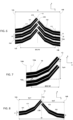
- the tread 10 comprises a plurality of patterns 13 which follow one another in the circumferential direction X. Each pattern 13 comprises a block 17 which extends, in the embodiment of the figure 1 , continuously from the first edge 14A of the tread 10 to the second edge 14B. This block 17 is delimited by oblique grooves 16A, 16B which are represented in gray on the figure 1 . In the tread, the oblique grooves 16A, 16B extend from the first edge 14A and from the second edge 14B to the central axis 12 of the tread.
- Block 17 also includes an incision 18 to promote the grip of the tire on snow-covered ground. In the tread, this incision 18 extends continuously from the first edge 14A to the second edge 14B. More particularly, the incision 18 here divides the block 17 into two parts of generally identical width.
- Each pattern 13 has a pitch P.
- This pitch P is determined as the distance between the centers of two adjacent oblique grooves framing a block 17. It will be noted that in the example of the figure 1 , the pitch P of the different tread patterns is identical.
- FIG. 2 represents an imprint of the tread of the figure 1 .
- This imprint was made dynamically under conditions as described above.
- the recessed elements such as the oblique grooves 16A, 16B, the incisions 18 are represented in white.
- Blocks 17 are shown in black. From this imprint, it is possible to determine a slenderness E of the oblique grooves ( picture 3 ) and an SD incision density in blocks 17 ( figure 4 ).
- FIG. 3 There picture 3 represents part of the footprint of the figure 2 centered on an oblique groove 16A.
- this oblique groove 16A starts from the first edge 14A and stops at the level of the central axis 12. It is possible to determine a slenderness E of the oblique groove 16A in the central part of the tread. bearing, that is, the level of its inclination in this central part. As has already been specified, the central part is delimited in part by the third edge 15A.
- the projected length Lpx is measured between a first point A and a second point B.
- Point A is determined at the intersection between a median 19 of the oblique groove 16A and the third edge 15A.
- the median 19 of the oblique groove 16A separates said oblique groove 16A into two oblique half-grooves of the same width.
- Point B is determined at the intersection between the median 19 of the oblique groove 16A and the central axis 12 of the tread 10.
- the slenderness E is here between 0.85 and 1.5 and preferably between 0.87 and 1.1.
- block 17 extends continuously from the first edge 14A to the second edge 14B.
- the incision 18 also extends continuously between a third point C and a fourth point D.
- the third point C is determined at the intersection between the incision 18 and the first edge 14A.
- the fourth point D is determined at the intersection between the incision 18 and the second edge 14B.
- the incision density SD in block 17 is between 10 mm -1 and 42 mm -1 and preferably between 30 mm -1 and 40 mm -1 .
- the incision density in block 17 is 33.33 mm ⁇ 1 .
- a tire according to a second embodiment of the invention comprises a tread 10 and two sidewalls 11A, 11B framing said tread 10.
- the sidewalls 11A, 11B form the side parts of the tire.
- Each sidewall has at its end a bead intended to sit on a rim of a wheel.
- the sidewalls 11A, 11B delimit the tread 10 at a first edge 14A and a second edge 14B.
- the first edge 14A and the second edge 14B frame a central axis 12 of the tread 10.
- This first edge 14A and this second edge 14B determine a tread width W.
- This tread width is here greater than 140 mm.
- the tread 10 also comprises a central part centered on the central axis 12 and whose width corresponds to 80% of the width W of said tread 10. This central part is delimited by a third edge 15A and a fourth edge 15B.
- the tread 10 comprises a plurality of patterns 13 which follow one another in the circumferential direction X. Each pattern 13 comprises a set of blocks comprising here a first block 171 and a second block 172. These blocks 171, 172 extend respectively to from the first edge 14A and from the second edge 14B of the tread 10 as far as the central axis 12. These blocks 171, 172 are delimited by oblique grooves 16A, 16B.
- the oblique grooves 16A, 16B extend respectively from the first edge 14A and from the second edge 14B to the central axis 12. These oblique grooves 16A, 16B promote the evacuation of water out of the tread when driving on wet pavement.
- Each block 171, 172 respectively comprises a first incision 181 and a second incision 182 to promote the grip of the tire on snow-covered ground.
- each incision 181, 182 respectively extends from continuously from the first edge 14A or the second edge 14B to one end 21A, 21B of the block 171, 17
- each incision 181, 182 divides the associated block 171, 172 into two parts of generally identical width.
- Each pattern 13 has a pitch P.
- This pitch P is determined as the distance between the centers of two adjacent oblique grooves framing a block 171, 172. It will be noted that in the example of the figure 5 , the pitch P of the different tread patterns is identical.
- FIG 6 represents an imprint of the tread of the figure 5 .
- This imprint was made dynamically under conditions as described above.
- the recessed elements such as the oblique grooves 16A, 16B, the incisions 181, 182 are represented in white.
- Blocks 171, 172 are shown in black. From this imprint, it is possible to determine a slenderness E of the oblique grooves ( figure 7 ) and a density of SD incisions in blocks 171, 172 ( figure 8 ).
- FIG. 7 represents part of the footprint of the figure 6 centered on an oblique groove 16A.
- this oblique groove 16A starts from the first edge 14A and stops at the level of the central axis 12. It is possible to determine a slenderness E of the oblique groove 16A in the central part of the tread. bearing, that is, the level of its inclination in this central part. As has already been specified, the central part is delimited in part by the third edge 15A.
- the projected length Lpx is measured between a first point A and a second point B.
- Point A is determined at the intersection between a median 19 of the oblique groove 16A and the third edge 15A.
- the median 19 of the oblique groove 16A separates said oblique groove 16A into two oblique half-grooves of the same width.
- Point B is determined at the intersection between the median 19 of the oblique groove 16 and the central axis 12 of the tread 10.
- the slenderness E is here between 0.85 and 1.5, and preferably between 0.87 and 1.1.
- FIG 8 represents part of the footprint of the figure 6 centered on the first block 171 and the second block 172.
- the first block 171 extends from the first edge 14A to the central axis 12 of the tread and the second block 172 is extends from the second edge 14B to the central axis 12 of the tread.
- the first incision 181 of the first block 171 extends continuously between a third point C and the end 21A of the block 171.
- the third point C is determined at the intersection between the first incision 181 and the first edge 14A.
- the second incision 182 of the second block 172 extends continuously between a fourth point D and the end 21B of the block 172.
- the fourth point D is determined at the intersection between the second incision 182 and the second edge 14B.
- the incision density SD in the set of blocks comprising the first block 171 and the second block 172 is between 10 mm -1 and 42 mm -1 and preferably between 30 mm -1 and 40 mm -1 .
- a tire according to a third embodiment of the invention comprises a tread 10 and two sidewalls 11A, 11B framing said tread 10.
- the sidewalls 11A, 11B delimit the tread 10 at a first edge 14A and a second edge 14B.
- the first edge 14A and the second edge 14B frame a central axis 12 of the tread 10.
- This first edge 14A and this second edge 14B determine a tread width W.
- This tread width is here greater than 140 mm.
- the tread 10 also comprises a central part centered on the central axis 12 and whose width corresponds to 80% of the width W of said tread 10. This central part is delimited by a third edge 15A and a fourth edge 15B.
- the tread 10 comprises a plurality of patterns 13 which follow one another in the circumferential direction X.
- Each pattern 13 comprises a set of blocks comprising here 4 blocks, including a first block 171, a second block 172, a third block 173 and a fourth block 174.
- the first block 171 and the third block 173 are located on the same side with respect to the central axis 12.
- the second block 172 and the fourth block 174 are located on the same side with respect to the central axis 12 in opposition with respect to the first block 171 and the third block 173.
- the first block 171 and the third block 173 are separated by a first cutout 231.
- the second block 172 and the fourth block 174 are separated by a second cutout 232.
- the first cutout 231 and the second cutout 232 are here grooves which will decouple the blocks between them in order to facilitate the flattening of the tread during rolling.
- the first cutout 231 is an incision
- the two blocks 171, 173 form a single block.
- the second cutout 232 is an incision
- the two blocks 172, 174 form a single block.
- the first block 171 and the fourth block 174 respectively extend from the first edge 14A and from the second edge 14B of the tread 10 as far as the first cutout 231 and the second cutout 232.
- the second block 172 and the fourth block 174 respectively extend from the first cutout 231 and the second cutout 232 to the central axis 12.
- the blocks 171, 172, 173, 174 are delimited by oblique grooves 16A, 16B .
- the oblique grooves 16A, 16B extend respectively from the first edge 14A and from the second edge 14B to the central axis 12. These oblique grooves 16A, 16B promote the evacuation of water out of the tread when driving on wet pavement.
- Each block 171, 172, 173, 174 respectively comprises a first incision 181, a second incision 182, a third incision 183 and a fourth incision 184 to promote the grip of the tire on snow-covered ground.
- the first incision 181 and the fourth incision 184 respectively extend from the first edge 14A or from the second edge 14B to an end which does not here lead to the first cutout 231 or the second cutout 232.
- the second incision 182 and the third incision 183 respectively extend from the second cutout 232 and the first cutout 231 to the end 21B of the block 172 or to the end 21A of block 173.
- Each incision 181, 182, 183, 184 divides the associated blocks 171, 172, 173, 174 into two half-blocks of generally identical width.
- Each pattern 13 has a pitch P.
- This pitch P is determined as the distance between the centers of two adjacent oblique grooves framing a block 171, 172, 173, 174. It will be noted that in the example of figure 9 , the pitch P of the different tread patterns is identical.
- FIG 10 represents an imprint of the tread of the figure 9 .
- This imprint was made dynamically under conditions as described above.
- the recessed elements such as the oblique grooves 16A, 16B, the incisions 181, 182, 183, 184 are represented in white.
- Blocks 171, 172, 173, 174 are shown in black. From this imprint, it is possible to determine a slenderness E of the oblique grooves ( figure 11 ) and a density of SD incisions in blocks 171, 172, 173, 174 ( figure 12 ).
- FIG 11 represents part of the footprint of the figure 10 centered on an oblique groove 16A.
- this oblique groove 16A starts from the first edge 14A and stops at the level of the central axis 12. It is possible to determine a slenderness E of the oblique groove 16A in the central part of the tread. bearing, that is, the level of its inclination in this central part. As has already been specified, the central part is delimited in part by the third edge 15A.
- the projected length Lpx is measured between a first point A and a second point B.
- Point A is determined at the intersection between a median 19 of the oblique groove 16A and the third edge 15A.
- the median 19 of the oblique groove 16A separates said oblique groove 16A into two oblique half-grooves of the same width.
- Point B is determined at the intersection between the median 19 of the oblique groove 16 and the central axis 12 of the tread 10.
- the slenderness E is here between 0.85 and 1.5, and preferably between 0.87 and 1.1.
- FIG 12 represents part of the footprint of the figure 10 centered on the first block 171, the second block 172, the third block 173 and the fourth block 174.
- the first block 171 extends from the first edge 14A to the first cutout 231.
- the third block 173 extends from first cutout 231 to end 21A of block 173.
- Second block 172 extends from end 21B of block 172 to second cutout 232.
- the fourth block is extends from the second cutout 232 to the second edge 14B.
- the first incision 181 of the first block 171 extends between a third point C and an end close to the first cutout 231.
- the third point C is determined at the intersection between the first incision 181 and the first edge 14A.
- Third incision 183 extends from first cutout 231 to end 21A of block 173.
- Second incision 182 extends from end 21B of second block 172 to second cutout 232
- the fourth incision 184 extends from the second cutout 232 to the fourth point D.
- the fourth point D is determined at the intersection between the fourth incision 184 and the second edge 14B.
- the incision density SD in the set of blocks comprising the first block 171, the second block 172, the third block 173 and the fourth block 174 is between 10 mm -1 and 42 mm -1 and preferably between 30 mm -1 and 40 mm -1 .
- this tire comprises a tread 10 and two sidewalls 11A, 11B framing said tread 10.
- the sidewalls 11A, 11B delimit the tread 10 at a first edge 14A and a second edge 14B.
- the first edge 14A and the second edge 14B frame a central axis 12 of the tread 10. This first edge 14A and this second edge 14B thus determine a tread width W.
- This tread width is here greater than 140 mm.
- the tread 10 also comprises a central part centered on the central axis 12 and whose width corresponds to 80% of the width W of said tread 10. This central part is delimited by a third edge 15A and a fourth edge 15B.
- the tread 10 comprises a plurality of patterns 13 which follow one another in the circumferential direction X.
- Each pattern 13 comprises a set of blocks comprising here 6 blocks, including a first block 171, a second block 172, a third block 173, a fourth block 174, a fifth block 175, a sixth block 176.
- the first block 171, the third block 173 and the fifth block 175 are located on the same side with respect to the central axis 12.
- the second block 172, the fourth block 174 and the sixth block 176 are located on the same side with respect to the central axis 12 in opposition with respect to the first block 171, the third block 173 and the fifth block 175.
- the first block 171 and the third block 173 are separated by a first cutout 231.
- the second block 172 and the fourth block 174 are separated by a second cutout 232.
- the third block 173 and the fifth block 175 are separated by a third cutout 233.
- the fourth block 174 and the sixth block 176 are separated by a fourth cutout 234.
- the first cutout 231, the second cutout 232, the third cutout 233, the fourth cutout 234 are here grooves which will decouple the blocks from each other in order to facilitate the flattening of the tread during rolling.
- the first cutout 231, the second cutout 232, the third cutout 233 and the fourth cutout 234 are grooves.
- first block 171 and the sixth block 176 respectively extend from the first edge 14A and from the second edge 14B of the tread 10 as far as the first cutout 231 and the fourth cutout 234.
- the third block 173 and the fourth block 174 respectively extend from the first cutout 231 and the fourth cutout 234 to the third cutout 233 and the second cutout 232.
- the fifth block 175 and the second block 172 respectively extend to from the third cutout 233 and the second cutout 232 to the central axis 12.
- the blocks 171, 172, 173, 174, 175, 176 are delimited by oblique grooves 16A, 16B.
- the oblique grooves 16A, 16B extend respectively from the first edge 14A and from the second edge 14B to the central axis 12. As already indicated, these oblique grooves 16A, 16B promote the evacuation of water from the tread when driving on wet pavement.
- Each block 171, 172, 173, 174, 175, 176 respectively comprises a first incision 181, a second incision 182, a third incision 183, a fourth incision 184, a fifth incision 185 and a sixth incision 186 to promote adhesion of the tire on snowy ground.
- the first incision 181 and the sixth incision 186 respectively extend from the first edge 14A or from the second edge 14B to an end which does not here lead to the first cutout 231 or the fourth cutout 234.
- the third incision 183 and the fourth incision 184 respectively extend from the first cutout 231 and the fourth cutout 234 to the third cutout 233 and to the second cutout 232.
- the fifth incision 185 and the second incision 182 extend respectively from the third cutout 233 and the second cutout 232 to the end 21A of the block 175 and to the end 21B of the block 172.
- Each incision 181, 182, 183, 184, 185, 186 divides the associated blocks 171, 172, 173, 174, 175, 176 in two half-blocks of generally identical width.
- Each pattern 13 has a pitch P.
- This pitch P is determined as the distance between the centers of two adjacent oblique grooves framing a block 171, 172, 173, 174, 175, 176. It will be noted that in the example of figure 13 , the pitch P of the different tread patterns is identical.
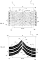
- the figure 14 represents a portion of a tire tread footprint figure 13 .
- This imprint was made dynamically under conditions as described above.
- the recessed elements such as the oblique grooves 16A, 16B, the incisions 181, 182, 183, 184, 185, 186 are represented in white.
- Blocks 171, 172, 173, 174, 175, 176 are shown in black. From an imprint, it is possible to determine a slenderness E of the oblique grooves and a density of incisions SD in blocks 171, 172, 173, 174, 175, 176.
- the determination of the slenderness E is done in the same way as in the examples of figure 8 , 12 .
- This slenderness E is between 0.85 and 1.5 and preferably between 0.87 and 1.1.
- FIG 14 thus represents part of the tire tread footprint figure 13 centered on the first block 171, the second block 172, the third block 173, the fourth block 174, the fifth block 175 and the sixth block 176.
- the first block 171 extends from the first edge 14A up to the first cutout 231.
- the third block 173 extends from the first cutout 231 to the third cutout 233.
- the fifth block 175 extends from the third cutout 233 to the central axis 12.
- the second block 172 extends from centerline 12 to second cutout 232.
- Fourth block 174 extends from second cutout to fourth cutout 234.
- Sixth block 176 extends from fourth cutout 234 to the second edge 14B.
- the first incision 181 of the first block 171 extends between a third point C and an end close to the first cutout 231.
- the third point C is determined at the intersection between the first incision 181 and the first edge 14A.
- Third incision 183 extends from first cutout 231 to third cutout 233.
- Fifth incision 185 extends from third cutout 233 to end 21A of block 175.
- the second incision 182 extends from end 21B of second block 172 to second cutout 232.
- Fourth cutout 184 extends from second cutout 232 to fourth cutout 234.
- Sixth cutout 176 s extends from an end of this incision close to the fourth cutout 234 to the fourth point D.
- the fourth point D is determined at the intersection between the sixth incision 186 and the second edge 14B.
- the incision density SD in the set of blocks comprising the first block 171, the second block 172, the third block 173, the fourth block 174, the fifth block 175 and the sixth block 176 is between 10 mm -1 and 42 mm -1 and preferably between 30 mm -1 and 40 mm -1 .
- FIG. 15 represents part of a footprint of a tread according to a fifth embodiment of the invention.
- This footprint part is centered on the blocks of a pattern of this tread. More particularly, this footprint part comprises, as in the previous embodiment, a first block 171, a second block 172, a third block 173, a fourth block 174, a fifth block 175 and a sixth block 176.
- the first block 171 extends from first edge 14A to first cutout 231.
- Third block 173 extends from first cutout 231 to third cutout 233.
- Fifth block 175 extends from third cutout 233 to 'to the central axis 12.
- the second block 172 extends from the central axis 12 to the second cutout 232.
- the fourth block 174 extends from the second cutout to the fourth cutout 234.
- the sixth block 176 extends from fourth cutout 234 to second edge 14B.
- the different blocks 171, 172, 173, 174, 175, 176 comprise at least one incision.
- the first block 171 comprises a first incision 181
- the third block 173 comprises a third incision 183.
- the fifth block 175 for its part comprises three incisions: a fifth incision 185a, a fifth incision bis 185b and a fifth incision ter 185c.
- the second block 172 comprises three incisions: a second incision 182a, a second bis incision 182b and a second ter incision 182c.
- the fourth block 174 comprises a fourth incision 184 and the sixth block 176 comprises a sixth incision 186. More particularly, the first incision 181 of the first block 171 extends between a third point C and an end close to the first cutout 231. The third point C is determined at the intersection between the first incision 181 and the first edge 14A. The third incision 183 extends from the first cutout 231 to the third cutout 233.
- the fifth incision 185a, the fifth incision bis 185b and the fifth incision ter 185c extend globally in the axial direction from a first side wall of the fifth block 175 up to a second side wall of this fifth block 175.
- the second incision 182a, the second bis incision 182b and the second ter incision 182c extend globally in the axial direction from a first wall of the second block 172 to a second side wall of this second block 172.
- the fourth incision 184 extends from the second cutout 232 to the fourth cutout 234.
- the sixth incision 186 extends from an end of this incision close to the fourth cutout 234 to a fourth point D.
- the fourth point D is determined at the intersection between the sixth incision 186 and the second edge 14B.
- the incisions 181, 183, 184, 186 divide their associated block 171, 173, 174, 176 into two half-blocks of generally identical width.
- the portion of the tread pattern shown in figure 15 thus comprises at least two adjacent blocks, such as the couple of blocks comprising the third block 173 and the fifth block 175 or the couple of blocks comprising the second block 172 and the fourth block 174.
- These adjacent blocks have a different number of incisions and also a different arrangement of incisions.
- the incision density SD in the set of blocks comprising the first block 171, the second block 172, the third block 173, the fourth block 174, the fifth block 175 and the sixth block 176 is between 10 mm -1 and 42 mm -1 and preferably between 30 mm -1 and 40 mm -1 .
- THE figures 16, 17 and 18 illustrate three patterns of the same tread belonging to three different types of patterns.
- This first pattern thus illustrates a first pattern having a first step P1.
- This first pattern comprises a first block 171, a second block 172, a third block 173, a fourth block 174, a fifth block 175 and a sixth block 176.
- the first block 171 extends from the first edge 14A to a first cutout 231.
- the third block 173 extends from the first cutout 231 to the third cutout 233.
- the fifth block 175 extends from the third cutout 233 to the central axis 12.
- the second block 172 extends from the extends from the central axis 12 to the second cutout 232.
- the fourth block 174 extends from the second cutout 232 to the fourth cutout 234.
- the sixth block 176 extends from the fourth cutout 234 to the second edge 14B.
- the different blocks 171, 172, 173, 174, 175, 176 each include an incision.
- the first block 171 comprises a first incision 181 which extends between a third point C and an end close to the first cutout 231.
- the third point C is determined at the intersection between the first incision 181 and the first edge 14A .
- the third block 173 comprises a third incision 183 which extends between the first cutout 231 and the third cutout 233.
- the fifth block 175 comprises a fifth incision 185 which extends between the third cutout 233 and an end 21A of the fifth block 175
- the second block 172 includes a second incision 182 which extends between an end 21B of the second block 172 and a second cutout 232.
- the fourth block 174 includes a fourth incision 184 which extends between the second cutout 232 and the fourth cutout 234.
- the sixth block 176 includes a sixth incision 186 which extends between the fourth cutout 234 and a fourth point D.
- the fourth point D is determined at the intersection between the sixth incision 186 and the second edge 14B.
- the incisions 181, 182, 183, 184, 185, 186 divide their associated block 171, 172, 173, 174, 175, 176 into two half-blocks of generally identical width.
- FIG 17 illustrates a second pattern having a second pitch P2.
- this second pattern comprises a first block 171, a second block 172, a third block 173, a fourth block 174, a fifth block 175 and a sixth block 176.
- the different blocks 171, 172, 173, 174 , 175, 176 each include an incision 181, 182, 183, 184, 185, 186.
- the arrangement of the blocks 171, 172, 173, 174, 175, 176 and , 184, 185, 186 reference is made to the above description of the first pattern.
- FIG 18 illustrates a third pattern having a third step P3.
- this third pattern comprises a first block 171, a second block 172, a third block 173, a fourth block 174, a fifth block 175 and a sixth block 176.
- the different blocks 171, 172 , 173, 174, 175, 176 each include an incision 181, 182, 183, 184, 185, 186.
- incision 181, 182, 183, 184, 185, 186 For a more detailed description of the arrangement of blocks 171, 172, 173, 174, 175, 176 and , 182, 183, 184, 185, 186, reference is made to the above description of the first pattern or the second pattern.
- the tread comprises an arrangement of N1 pitch patterns P1, N2 pitch patterns P2 and N3 pitch patterns P3. It is thus possible to determine an average incision density SDmoy corresponding to the average of the incision densities SD1, SD2, SD3 of the patterns of steps P1, P2, P3 over the entire circumference of the tread.
- the pitch patterns P1, P2, P3 are arranged randomly on the tread in order to limit the emergence of noise from the tire when rolling.
- the arrangement between pitch patterns P1, P2 and P3 could be as follows: P1 P1 P2 P1 P2 P2 P2 P2 P1 P1 P2 P1 P1 P1 P2 P2 P3 P2 P2 P3 P2 P1 P2 P2 P1 P1 P1 P1 P2 P1 P1 P1 P1 P2 P1 P1 P1 P1 P2 P1 P1 P1 P2 P2 P3 P3 P3 P2 P2 P3 P3 P3 P3 P3 P3 P3 P3 P2 P2 P1 P2 P2 P3 P2 P1 P2 P2 P1 P2 P2 P1 P1 P2 P2 P1 P1 P1 P2 P3 P2 P1 P1 P1 P2 P3 P2 P1.
- Such an arrangement would then comprise 21 pitch patterns P1, 35 pitch patterns P2 and 13 pitch patterns P3.
- a pitch P is determined as the distance between the centers of two adjacent oblique grooves framing a block.
- these are measured in groups of patterns belonging to the same type of pattern, for example in groups of patterns P1 P1 P1, P2 P2 P2 and P3 P3 P3 .
- each block is formed from a rubber material.
- the composition of this rubber material has a glass transition temperature of between -40°C and -10°C, and preferably between -35°C and -15°C and a shear modulus measured at 60° C. between 0.5 MPa and 2 MPa, and preferably between 0.7 MPa and 1.5 MPa.
- the solution SBR of this preferred embodiment is a copolymer of styrene and butadiene prepared in solution. It has the characteristic of wearing a silanol function and an amine function.
- the silanol function of the SBR solution bearing a silanol function and an amine function can for example be introduced by hydrosilylation of the elastomer chain by a silane bearing an alkoxysilane group, followed by hydrolysis of the alkoxysilane function into silanol function.
- the silanol function of the SBR solution carrying a silanol function and an amine function can also be introduced by reaction of the living elastomer chains with a cyclic polysiloxane compound as described in EP 0 778 311 .
- the amine function of the SBR solution carrying a silanol function and an amine function can for example be introduced by initiating the polymerization with an initiator carrying such a function.
- An SBR solution bearing a silanol function and an amine function can also be prepared by reacting living elastomer chains with a compound bearing an alkoxysilane function and an amine function according to the procedure described in the patent application EP 2 285 852 , followed by hydrolysis of the alkoxysilane function to silanol function.
- the silanol function and the amine function are preferably located inside the chain of the SBR solution, outside the chain ends.
- the hydrolysis reaction of the alkoxysilane function carried by the SBR solution as a silanol function can be carried out according to the procedure described in the patent application EP 2 266 819 A1 or else by a step of stripping the solution containing the SBR solution.
- the amine function can be a primary, secondary or tertiary, preferably tertiary, amine.
- the blocks have a relatively low maximum radial height Hmax when new. This radial height is between 5.5 mm and 9 mm and preferably between 6 mm and 7.5 mm. This relatively low radial height could penalize grip on wet ground.
- the radial height is compensated by the strong slenderness of the tread and by the characteristics of the material used containing the SBR solution. This makes it possible to ensure good grip of the tire on wet ground over time.
- blind incisions which do not extend over the entire length of a block and which therefore do not join a cutout for all the ends of the cutouts.
- all the incisions of the blocks of the pattern open into a cutout.
- all the incisions of the blocks of the pattern are blind.
- the figure 18 has a number of oblique cutouts 231, 232, 233, 234 equal to four.
- the number of oblique cutouts on the tread is greater than four.
- the oblique cutouts 231, 232, 233, 234 have a depth identical to that of the oblique grooves 16A, 16B.
- the oblique cutouts have a depth less than that of the oblique grooves 16A, 16B.
- the patterns have an overall simple arrangement of the block(s).
- the patterns may have more complex arrangements.
- each pattern can comprise several adjacent blocks which follow one another in the circumferential direction. These adjacent blocks are delimited by secondary oblique grooves.
- These secondary oblique grooves may have a slenderness identical to the main oblique grooves 16A, 16B.
- the slenderness of the secondary oblique grooves is different from that of the main oblique grooves 16A, 16B.
Landscapes
- Chemical & Material Sciences (AREA)
- Engineering & Computer Science (AREA)
- Mechanical Engineering (AREA)
- Health & Medical Sciences (AREA)
- Chemical Kinetics & Catalysis (AREA)
- Medicinal Chemistry (AREA)
- Polymers & Plastics (AREA)
- Organic Chemistry (AREA)
- Oil, Petroleum & Natural Gas (AREA)
- Tires In General (AREA)
Description
La présente invention concerne un pneumatique pour véhicule automobile dont la bande de roulement comprend une pluralité de rainures obliques présentant un fort élancement. L'invention est plus particulièrement adaptée pour un pneumatique destiné à équiper un véhicule de tourisme ou une camionnette.The present invention relates to a tire for a motor vehicle, the tread of which comprises a plurality of oblique grooves having a strong slenderness. The invention is more particularly suitable for a tire intended to equip a passenger vehicle or a van.
De manière connue, un pneumatique destiné à équiper un véhicule automobile comporte une bande de roulement. Cette bande de roulement comprend une surface de roulement et deux bords délimitant ladite surface de roulement. La surface de roulement correspond à l'ensemble des points de la bande de roulement qui entrent en contact avec une chaussée lorsque le pneumatique, gonflé à sa pression de référence et écrasé par une charge de référence, roule sur cette chaussée. La pression de gonflage de référence et la charge de référence sont définies dans les conditions d'utilisation du pneumatique, conditions précisées notamment par la norme E.T.R.T.O.. La surface de roulement de la bande de roulement comprend des creux formés par diverses rainures, telles que des rainures obliques. Les rainures obliques constituent des canaux destinés à évacuer l'eau sur les côtés de la bande de roulement. Il est connu du document
En outre, il existe une demande de plus en plus importante pour des pneumatiques dits « quatre saisons » présentant un excellent compromis d'adhérence sur sol enneigé/sol mouillé tout en préservant les performances sur sol sec. Ces pneumatiques quatre saisons ont pour objectif de rouler en sécurité toute l'année quelle que soit la météo. Ces pneumatiques ont généralement reçu la certification hiver 3PMSF (pour 3 Peak Mountain Snow Flake). Cette certification est notamment indiquée sur l'un ou les deux flancs desdits pneumatiques.In addition, there is an increasing demand for so-called “four-season” tires having an excellent compromise of grip on snowy ground/wet ground while preserving performance on dry ground. These four-season tires are designed to drive safely all year round, whatever the weather. These tires have generally received 3PMSF winter certification (for 3 Peak Mountain Snow Flake). This certification is indicated in particular on one or both sidewalls of said tires.
Il existe donc un besoin d'obtenir un pneumatique quatre saisons présentant des performances d'adhérence sur sol sec et sur sol mouillé qui soient proches d'un pneumatique été tout en assurant une très grande sécurité sur un sol enneigé et une résistance à l'usure améliorée.There is therefore a need to obtain an all-season tire with grip performance on dry ground and on wet ground which is close to that of a summer tire while ensuring very high safety on snowy ground and resistance to improved wear.
La présente invention vise à remédier à cet inconvénient.The present invention aims to remedy this drawback.
Plus particulièrement, la présente invention vise à améliorer le compromis d'adhérence sur sol enneigé/sol mouillé pour un pneumatique quatre saisons tout en améliorant les performances en usure d'un tel pneumatique.More particularly, the present invention aims to improve the grip compromise on snowy ground/wet ground for an all-season tire while improving the wear performance of such a tire.
L'invention concerne un pneumatique comportant une bande de roulement directionnelle.The invention relates to a tire comprising a directional tread.
Par « pneumatique », on entend tous les types de bandage en matériau caoutchoutique soumis en roulage à une pression interne ou non soumis à une telle pression interne en roulage (c'est le cas d'un bandage sans air comprimé, par exemple, de type Tweel™).The term “tyre” is understood to mean all types of tire made of rubber material subjected to internal pressure when driving or not subjected to such internal pressure when driving (this is the case of a tire without compressed air, for example, Tweel ™ type).
Par « matériau caoutchoutique », on entend un élastomère diénique, c'est-à-dire de manière connue un élastomère issu d'au moins en partie (c'est-à-dire homopolymère ou copolymère) de monomères diènes (monomères porteurs de doubles liaisons carbone-carbone, conjuguées ou non).By “rubber material”, is meant a diene elastomer, that is to say in known manner an elastomer derived from at least in part (that is to say homopolymer or copolymer) of diene monomers (monomers carrying carbon-carbon double bonds, conjugated or not).
Par « bande de roulement » d'un pneumatique, on entend une quantité de matériau caoutchoutique délimitée par une surface de roulement. La surface de roulement regroupe l'ensemble des points du pneumatique qui vont entrer en contact avec un sol dans des conditions usuelles de roulage. Pour un pneumatique, les « conditions usuelles » de roulage sont les conditions d'utilisation définies par la norme ETRTO (European Tyre and Rim Technical Organisation). Ces conditions d'utilisation précisent la pression de gonflage de référence correspondant à la capacité de charge du pneu indiquée par son indice de charge et son code vitesse. Ces conditions d'utilisation peuvent aussi être dites « conditions nominales » ou « conditions d'usage ».By “tread” of a tire is meant a quantity of rubber material delimited by a tread surface. The running surface groups together all the points of the tire which will come into contact with the ground under normal driving conditions. For a tyre, the “usual driving conditions” are the conditions of use defined by the ETRTO standard (European Tire and Rim Technical Organisation). These conditions of use specify the reference inflation pressure corresponding to the load capacity of the tire indicated by its load index and its speed code. These conditions of use can also be called “nominal conditions” or “conditions of use”.
Par « bande de roulement directionnelle », on entend une bande de roulement dont les éléments de sculpture sont spécifiquement agencés pour optimiser les caractéristiques comportementales en fonction d'un sens de rotation prédéterminé. Ce sens de rotation est classiquement indiqué par une flèche sur le flanc du pneumatique.“Directional tread” means a tread whose tread elements are specifically arranged to optimize the behavioral characteristics as a function of a predetermined direction of rotation. This direction of rotation is conventionally indicated by an arrow on the sidewall of the tire.
La bande de roulement de l'invention comprend un axe central et deux bords encadrant ledit axe central et déterminant une largeur de bande de roulement W, la largeur de la bande de roulement étant supérieure ou égale à 140 mm. Cette largeur de bande de roulement est déterminée à partir d'une empreinte réalisée de manière dynamique. Afin d'obtenir une telle empreinte, on dépose de l'encre noire sur une partie de la bande de roulement du pneumatique et on vient faire rouler cette partie encrée sur une feuille de papier selon une certaine vitesse d'avancement. Les conditions de réalisation d'une telle empreinte se font à la pression nominale, pour une charge correspondant à 0,76 fois la charge nominale et à une vitesse d'avancement de 100 mm/s. Par exemple pour un pneumatique de dimension 205/55R16 91V, les conditions de réalisation de l'empreinte se feront à une pression de 2,5 bar et pour une charge de 480 daN. L'ensemble des mesures pour la détermination de l'élancement E, de la densité d'incisions SD, de la densité moyenne d'incisions SDmoy se font par la suite à partir d'une empreinte de la bande de roulement roulant sur un support aux conditions de charge, de pression et de vitesse d'avancement telles que décrites ci-dessus.The tread of the invention comprises a central axis and two edges flanking said central axis and determining a tread width W, the width of the tread being greater than or equal to 140 mm. This tread width is determined from a dynamically generated footprint. In order to obtain such an imprint, black ink is deposited on part of the tread of the tire and this inked part is rolled on a sheet of paper at a certain forward speed. The conditions for making such an imprint are at nominal pressure, for a load corresponding to 0.76 times the nominal load and at a forward speed of 100 mm/s. For example, for a tire of size 205/55R16 91V, the conditions for making the footprint will be at a pressure of 2.5 bar and for a load of 480 daN. All the measurements for determining the slenderness E, the density of incisions SD, the average density of incisions SDmoy are then made from an imprint of the tread rolling on a support under the load, pressure and forward speed conditions as described above.
La bande de roulement comprend une pluralité de motifs qui se succèdent selon la direction circonférentielle, chaque motif ayant un pas P.The tread comprises a plurality of patterns which follow one another in the circumferential direction, each pattern having a pitch P.
« Par motif », on entend un ensemble de bloc qui est répété selon la direction circonférentielle. Cette répétition peut se faire à iso-dimension. La bande de roulement est dite alors monopas. En variante, cette répétition peut se faire avec des dimensions différentes, notamment des valeurs de pas différentes. La bande de roulement est dite alors multipas. Avantageusement, le nombre de valeurs de pas différent pour une bande de roulement multipas est compris entre 3 et 5 pas. De manière préférentielle, l'ensemble de bloc du motif s'étend sur toute la largeur W de bande de roulement. Chaque ensemble de bloc comprend au moins un bloc. « Par bloc », on entend un élément en relief délimité par des rainures et comprenant des parois latérales et une face de contact, cette dernière étant destinée à venir en contact avec un sol pendant le roulage.“By pattern” is meant a set of blocks which is repeated in the circumferential direction. This repetition can be done at iso-dimension. The tread is then said to be single-pitch. As a variant, this repetition can be done with different dimensions, in particular different pitch values. The tread is then said to be multistep. Advantageously, the number of different pitch values for a multi-pitch tread is between 3 and 5 pitches. Preferably, the block assembly of the pattern extends over the entire width W of the tread. Each block set includes at least one block. “By block” is meant an element in relief delimited by grooves and comprising side walls and a contact face, the latter being intended to come into contact with the ground during rolling.
« Par direction circonférentielle », on entend une direction qui est tangente à tout cercle centré sur l'axe de rotation. Cette direction est perpendiculaire à la fois à une direction axiale et à une direction radiale."By circumferential direction" is meant a direction which is tangent to any circle centered on the axis of rotation. This direction is perpendicular to both an axial direction and a radial direction.
« Par direction axiale », on entend une direction parallèle à l'axe de rotation du pneumatique.“Axial direction” means a direction parallel to the axis of rotation of the tire.
« Par direction radiale », on entend une direction qui est perpendiculaire à l'axe de rotation du pneumatique (cette direction correspond à la direction de l'épaisseur de la bande de roulement au centre de ladite bande de roulement).“Radial direction” means a direction which is perpendicular to the axis of rotation of the tire (this direction corresponds to the direction of the thickness of the tread at the center of said tread).
« Par rainure », on entend une découpure dont la distance entre les parois de matière est supérieure à 2 mm."By groove" is meant a cutout whose distance between the walls of material is greater than 2 mm.
« Par rainure oblique », on entend une rainure dont l'orientation principale fait un angle aigu compris entre 20° et 70° avec la direction axiale.“By oblique groove”, is meant a groove whose main orientation makes an acute angle of between 20° and 70° with the axial direction.
« Par rainure circonférentielle », on entend une rainure dont l'orientation principale est selon la direction circonférentielle."Circumferential groove" means a groove whose main orientation is in the circumferential direction.
« Par incision », on entend une découpure dont la distance entre les parois de matière est inférieure ou égale à 2 mm. Il est également déterminé que la profondeur d'une incision dans la bande de roulement est supérieure ou égale à 1 mm. Dès lors, des découpures esthétiques, de type « grain d'orge », dont la profondeur est inférieure à 1 mm dans la bande de roulement ne sont pas considérés comme des incisions.“Incision” means a cutout whose distance between the walls of material is less than or equal to 2 mm. It is also determined that the depth of an incision in the tread is greater than or equal to 1 mm. Consequently, aesthetic cutouts, of the "barleycorn" type, the depth of which is less than 1 mm in the tread are not considered as incisions.
Les motifs délimitent une pluralité de rainures obliques, chaque rainure oblique s'étendant d'un des bords de la bande de roulement vers l'axe central.The patterns delimit a plurality of oblique grooves, each oblique groove extending from one of the edges of the tread towards the central axis.
Dans une partie centrale de la bande de roulement centrée sur l'axe central et de largeur correspondant à 80% de la largeur W de ladite bande de roulement, tout ou partie des rainures obliques de la pluralité de rainures obliques a un élancement compris entre 0,85 et 1,5 et de préférence entre 0,87 et 1,1. Avec une telle valeur d'élancement dans la partie centrale de la bande de roulement, on s'assure d'une meilleure évacuation de l'eau hors de la bande de roulement et on limite en conséquence les risques d'hydroplanage.In a central part of the tread centered on the central axis and with a width corresponding to 80% of the width W of said tread, all or part of the oblique grooves of the plurality of oblique grooves has a slenderness of between 0 .85 and 1.5 and preferably between 0.87 and 1.1. With such a slenderness value in the central part of the tread, better evacuation of the water out of the tread is ensured and the risks of hydroplaning are consequently limited.
« Par élancement » E, on entend le rapport entre une longueur projetée Lpx de la rainure oblique selon la direction circonférentielle avec la moitié de la largeur W de la largeur de la partie centrale de la bande de roulement, tel que 
Chaque motif comprend au moins une incision. Une densité d'incision SD dans le motif est comprise entre 10 mm-1 et 70 mm-1.Each pattern includes at least one incision. An SD incision density in the pattern is between 10 mm -1 and 70 mm -1 .
Par « densité d'incision SD » on entend le rapport entre la somme de la/les longueur(s) projetée(s) lpyi de la/desdites incision(s) selon une direction axiale sur le produit du pas P du motif et de la largeur W de la bande de roulement tel que 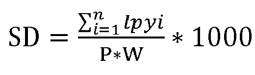
Les caractéristiques de la bande de roulement ainsi énoncées permettent d'obtenir une pneumatique de type quatre saisons présentant un excellent compromis d'adhérence sur sol enneigé/sol mouillé tout en améliorant les performances en usure de ce pneumatique.The characteristics of the tread thus stated make it possible to obtain a tire of the four-season type having an excellent compromise of grip on snowy ground/wet ground while improving the wear performance of this tire.
Dans un mode de réalisation préférentiel, la bande de roulement comprend différent types de motifs Mj, avec j supérieur ou égal à 2, les motifs appartenant à un même type de motif ayant un même pas, le pas entre des motifs appartenant à deux types de motifs différents étant différent, et en ce que la densité moyenne d'incision (SDmoy) est comprise entre 10 mm-1 et 70 mm-1, ladite densité moyenne d'incisions (SDmoy) correspondant à la moyenne des densités d'incisions SDj des motifs des différents types de motifs Mj sur toute la circonférence de la bande de roulement, ladite densité moyenne d'incisions SDmoy étant pondérée en fonction du nombre de motifs Nj par type de motif Mj et du pas Pj des motifs appartenant au type de motif Mj sur ladite circonférence de la bande de roulement, tel que 
Préférentiellement, la densité d'incision SD ou la densité moyenne d'incision SDmoy est supérieure à 25 mm-1 et/ou inférieure à 50 mm-1.Preferably, the incision density SD or the mean incision density SDmoy is greater than 25 mm −1 and/or less than 50 mm −1 .
Préférentiellement, la densité d'incision SD ou la densité moyenne d'incision SDmoy est comprise entre 30 mm-1 et 40 mm-1.Preferably, the incision density SD or the mean incision density SDmoy is between 30 mm −1 and 40 mm −1 .
Dans un mode de réalisation préférentiel, chaque motif comprenant un ensemble de bloc comportant au moins un bloc, dans lequel ledit bloc a une hauteur radiale maximale Hmax à l'état neuf comprise entre 5,5 mm et 9 mm et de préférence entre 6 mm et 7,5 mm.In a preferred embodiment, each pattern comprising a set of blocks comprising at least one block, in which said block has a maximum radial height Hmax in new condition of between 5.5 mm and 9 mm and preferably between 6 mm and 7.5mm.
En diminuant la hauteur radiale du bloc, on améliore globalement la résistance au roulement du pneumatique ainsi que le comportement routier sur sol sec. Le fort élancement de la bande de roulement permet de compenser, au moins en partie, une hauteur radiale de bloc plus faible pour la performance d'évacuation de l'eau.By reducing the radial height of the block, the overall rolling resistance of the tire is improved as well as road behavior on dry ground. The strong slenderness of the tread helps to offset, at least in part, a lower radial block height for water evacuation performance.
Dans un mode de réalisation préférentiel, chaque motif comprend au moins deux blocs adjacents et le nombre d'incision dans chaque bloc est supérieur ou égal à une incision. Le nombre d'incision et/ou l'arrangement desdites incisions est différent entre les deux blocs adjacents.In a preferred embodiment, each pattern comprises at least two adjacent blocks and the number of incisions in each block is greater than or equal to one incision. The number of incisions and/or the arrangement of said incisions is different between the two adjacent blocks.
Dans un mode de réalisation préférentiel, chaque bloc est en matériau caoutchoutique. La composition de ce matériau caoutchoutique a une température de transition vitreuse Tg comprise entre -40°C et -10°C, et préférentiellement entre -35°C et -15°C. La température de transition vitreuse Tg du matériau caoutchoutique est mesurée au moyen d'un calorimètre différentiel (« differential scanning calorimeter »). L'analyse est réalisée selon les requis de la norme ASTM D3418.In a preferred embodiment, each block is made of rubber material. The composition of this rubber material has a glass transition temperature Tg of between -40°C and -10°C, and preferably between -35°C and -15°C. The glass transition temperature Tg of the rubber material is measured by means of a differential scanning calorimeter. The analysis is carried out according to the requirements of the ASTM D3418 standard.
La composition de ce matériau caoutchoutique a également un module de cisaillement G* mesuré à 60°C compris entre 0,5 MPa et 1,5 MPa, préférentiellement entre 0,8 MPa et 1,1 MPa. Le module de cisaillement G* caractérise la composition du matériau caoutchoutique. Cette propriété mécanique est mesurée sur un viscoanalyseur (Metravib VA4000), selon la norme ASTM D 5992-96. On enregistre la réponse d'un échantillon de composition vulcanisée (éprouvette cylindrique de 4 mm d'épaisseur et de 400 mm2 de section), soumis à une sollicitation sinusoïdale en cisaillement simple alterné, à la fréquence de 10Hz, lors d'un balayage en température. Les résultats exploités correspondent au module complexe de cisaillement dynamique G* mesuré à 60°C. La valeur de G* mesurée à 60°C est représentative de la rigidité du matériau caoutchoutique, c'est-à-dire de sa résistance à la déformation élastique.The composition of this rubber material also has a shear modulus G* measured at 60° C. of between 0.5 MPa and 1.5 MPa, preferably between 0.8 MPa and 1.1 MPa. The shear modulus G* characterizes the composition of the rubber material. This mechanical property is measured on a viscoanalyzer (Metravib VA4000), according to standard ASTM D 5992-96. The response of a sample of vulcanized composition (cylindrical specimen 4 mm thick and 400 mm 2 in section) subjected to a sinusoidal stress in alternating simple shearing, at the frequency of 10 Hz, during a sweep is recorded. in temperature. The results used correspond to the complex dynamic shear modulus G* measured at 60°C. The value of G* measured at 60° C. is representative of the rigidity of the rubber material, that is to say of its resistance to elastic deformation.
Au niveau de la composition chimique, le mélange élastomérique du ou des blocs comprend 100 pce (parties en poids pour cent parties en poids d'élastomère) d'un élastomère dinénique modifié). Par définition, un élastomère diénique est un homopolymère ou un copolymère, issu aux moins en partie des monomères diènes, c'est-à-dire des monomères porteurs de deux doubles liaisons carbone-carbone conjuguées ou non. Préférentiellement, le mélange élastomérique comprend l'élastomère diénique modifié à un taux au moins égal à 20 pce.In terms of chemical composition, the elastomeric mixture of the block(s) comprises 100 phr (parts by weight per hundred parts by weight of elastomer) of a modified dine elastomer). By definition, a diene elastomer is a homopolymer or a copolymer, derived at least in part from diene monomers, that is to say monomers carrying two carbon-carbon double bonds, whether conjugated or not. Preferably, the elastomeric mixture comprises the modified diene elastomer at a level at least equal to 20 phr.
L'élastomère diénique modifié comprend au moins un groupe fonctionnel comprenant un atome de silicium, ce dernier se situant au sein de la chaîne principale, y compris les extrémités de chaîne. L'expression « atome se situant au sein de la chaîne principale de l'élastomère, y compris les extrémités de chaîne », s'entend ici comme n'étant pas un atome pendant (ou latéral) le long de la chaîne principale de l'élastomère mais étant un atome intégré à la chaîne principale. Ainsi, la composition de l'au moins un bloc comprend préférentiellement un mélange élastomérique, ledit mélange élastomérique comportant un élastomère diénique modifié comprenant au moins un groupe fonctionnel comprenant un atome de silicium, ce dernier se situant au sein de la chaîne principale de l'élastomère y compris les extrémités de chaîne.The modified diene elastomer comprises at least one functional group comprising a silicon atom, the latter being located within the main chain, including the chain ends. The expression "atom located within the main chain of the elastomer, including the chain ends", is understood here as not being a pendent (or lateral) atom along the main chain of the elastomer. elastomer but being an atom integrated into the main chain. Thus, the composition of the at least a block preferably comprises an elastomeric mixture, said elastomeric mixture comprising a modified diene elastomer comprising at least one functional group comprising a silicon atom, the latter being located within the main chain of the elastomer including the chain ends.
L'élastomère diénique modifié comprenant un groupe fonctionnel comprenant un atome de silicium peut être un élastomère modifié comprenant au moins une fonction silanol située en une extrémité de la chaîne principale de l'élastomère. Des élastomères diéniques modifiés correspondant sont décrits notamment dans les documents
Alternativement et de manière préférentielle, le groupe fonctionnel se situe dans la chaîne élastomère principale, on dira alors que l'élastomère diénique est couplé ou encore fonctionnalisé en milieu de chaîne. L'atome de silicium du groupe fonctionnel lie alors les deux branches de la chaîne principale de l'élastomère diénique. L'atome de silicium du groupe fonctionnel peut être substitué par au moins une fonction alcoxy, éventuellement totalement ou partiellement hydrolysée en hydroxyle.Alternatively and preferably, the functional group is located in the main elastomer chain, it will then be said that the diene elastomer is coupled or else functionalized in the middle of the chain. The silicon atom of the functional group then links the two branches of the main chain of the diene elastomer. The silicon atom of the functional group can be substituted by at least one alkoxy function, optionally totally or partially hydrolyzed to hydroxyl.
De manière particulièrement avantageuse, l'élastomère diénique modifié est majoritairement fonctionnalisé en milieu de chaîne par un groupe alcoxysilane lié aux deux branches de l'élastomère diénique modifié par l'intermédiaire de l'atome de silicium.In a particularly advantageous manner, the modified diene elastomer is predominantly functionalized in the middle of the chain by an alkoxysilane group bonded to the two branches of the modified diene elastomer via the silicon atom.
L'atome de silicium du groupe fonctionnel peut être substitué par au moins une fonction alcoxy, éventuellement totalement ou partielle hydrolysée en hydroxyle, l'atome de silicium peut également être substitué, directement ou par l'intermédiaire d'un radical hydrocarboné divalent, par au moins une autre fonction comprenant au moins un hétéroatome choisi parmi N, S, O, P. De préférence, l'atome de silicium est substitué par au moins une autre fonction par l'intermédiaire d'un radical hydrocarboné divalent, plus préférentiellement aliphatique linéaire en C1- C18. On peut, à titre d'exemple, citer parmi ces autres fonctions, les amines primaires, secondaires ou tertiaires, cycliques ou non, les isocyanates, les imines, les cyano, les thiols, les carboxylates, les époxydes, les phosphines primaires, secondaires ou tertiaires. L'autre fonction est de préférence une amine tertiaire, plus préférentiellement un groupement diéthylamino- ou diméthylamino-. La fonction alcoxy est de préférence méthoxy, éthoxy, butoxy ou propoxy. Des élastomères diéniques modifiés correspondant à ces variantes sont décrits notamment dans les documents
La modification de l'élastomère diénique par au moins un groupe fonctionnel comprenant un atome de silicium, n'exclut pas une autre modification de l'élastomère par exemple en extrémité de chaîne par une fonction amine introduite lors de l'initiation de la polymérisation, tel que décrit dans
En particulier, l'élastomère diénique modifié comprenant un groupe fonctionnel comprenant un atome de silicium est avantageusement un élastomère modifié comprenant au sein de sa structure au moins un groupe alcoxysilane lié à l'élastomère par l'atome de silicium, et au moins une fonction comprenant un atome d'azote.In particular, the modified diene elastomer comprising a functional group comprising a silicon atom is advantageously a modified elastomer comprising within its structure at least one alkoxysilane group bonded to the elastomer via the silicon atom, and at least one comprising a nitrogen atom.
Dans ce cas, l'élastomère diénique modifié présente avantageusement au moins deux, de préférence l'ensemble des caractéristiques suivantes :
- la fonction comprenant un atome d'azote est une amine tertiaire, plus particulièrement un groupement diéthylamino- ou diméthylamino-,
- la fonction comprenant un atome d'azote est portée par le groupe alcoxysilane par l'intermédiaire d'un groupement espaceur défini comme un radical hydrocarboné aliphatique en C1-C10, plus préférentiellement encore le radical hydrocarboné linéaire en C2 ou C3,
- le groupe alcoxysilane est un méthoxysilane ou un éthoxysilane, éventuellement partiellement ou totalement hydrolysé en silanol
- the function comprising a nitrogen atom is a tertiary amine, more particularly a diethylamino- or dimethylamino- group,
- the function comprising a nitrogen atom is carried by the alkoxysilane group via a spacer group defined as a C 1 -C 10 aliphatic hydrocarbon radical, more preferably still the linear C 2 or C 3 hydrocarbon radical,
- the alkoxysilane group is a methoxysilane or an ethoxysilane, optionally partially or totally hydrolyzed to silanol
De tels élastomères diéniques modifiées peuvent être obtenus par le procédé décrit dans la demande de brevet
Préférentiellement, l'élastomère diénique modifié selon l'invention est un polymère de 1,3-butadiène, plus préférentiellement un copolymère butadiène-styrène (SBR).Preferably, the modified diene elastomer according to the invention is a 1,3-butadiene polymer, more preferably a butadiene-styrene copolymer (SBR).
Avantageusement, l'élastomère diénique modifié présente une température de transition vitreuse comprise dans un domaine allant de -105°C à -70°C, de préférence de -100°C à -75°C et de préférence de -95°C à -80°C.Advantageously, the modified diene elastomer has a glass transition temperature comprised in a range ranging from -105°C to -70°C, preferably from -100°C to -75°C and preferably from -95°C to -80°C.
L'élastomère diénique modifié selon l'invention peut être, selon différentes variantes, utilisé seul dans le mélange élastomérique ou en coupage avec au moins un autre élastomère diénique conventionnellement utilisé en pneumatique, qu'il soit étoilé, couplé, fonctionnalisé par exemple à l'étain ou au silicium, ou non.The modified diene elastomer according to the invention can be, according to different variants, used alone in the elastomeric mixture or in a blend with at least one other diene elastomer conventionally used in tires, whether it is star-shaped, coupled, functionalized for example with tin or silicon, or not.
Egalement du point de vue de sa composition chimique, le mélange élastomérique de la bande de roulement selon l'invention comprend une résine plastifiante de type résine thermoplastique à un taux au moins égal à 10 pce, de préférence de 10 à 100 pce, de préférence de 20 à 50 pce.Also from the point of view of its chemical composition, the elastomeric mixture of the tread according to the invention comprises a plasticizing resin of the thermoplastic resin type at a rate at least equal to 10 phr, preferably from 10 to 100 phr, preferably from 20 to 50 pc.
Dans un mode de réalisation non limitatif, le pneumatique a une certification hiver 3PMSF, ladite certification étant indiquée sur un flanc du pneumatique.In one non-limiting embodiment, the tire has a 3PMSF winter certification, said certification being indicated on a sidewall of the tire.
La présente invention sera mieux comprise à la lecture de la description détaillée de modes de réalisation pris à titre d'exemples nullement limitatifs et illustrés par les dessins annexés sur lesquels :
- La
figure 1 est une vue schématique montrant une partie d'une bande de roulement d'un pneumatique selon un premier mode de réalisation de l'invention ; - La
figure 2 est une empreinte de la bande de roulement de lafigure 1 ; - La
figure 3 est une partie de l'empreinte de lafigure 2 centrée sur une rainure oblique ; - La
figure 4 est une partie de l'empreinte de lafigure 2 centrée sur un motif ; - La
figure 5 est une vue schématique montrant une partie d'une bande de roulement d'un pneumatique conforme à l'invention selon un second mode de réalisation ; - La
figure 6 est une empreinte de la bande de roulement de lafigure 5 ; - La
figure 7 est une partie de l'empreinte de lafigure 6 centrée sur une rainure oblique ; - La
figure 8 est une partie de l'empreinte de lafigure 6 centrée sur un motif ; - La
figure 9 est une vue schématique montrant une partie d'une bande de roulement d'un pneumatique conforme à l'invention selon un troisième mode de réalisation de l'invention ; - La
figure 10 est une empreinte de la bande de roulement de lafigure 9 ; - La
figure 11 est une partie de l'empreinte de lafigure 10 centrée sur une rainure oblique ; - La
figure 12 est une partie de l'empreinte de lafigure 10 centrée sur un motif ; - La
figure 13 est une partie d'une empreinte d'une bande de roulement d'un pneumatique conforme à l'invention selon un quatrième mode de réalisation de l'invention ; - La
figure 14 est une partie de l'empreinte de lafigure 13 centré sur un motif ; - La
figure 15 est une partie d'une empreinte d'une bande de roulement d'un pneumatique conforme à l'invention selon un cinquième mode de réalisation de l'invention ; - La
figure 16 est une partie d'une empreinte d'une bande de roulement multipas d'un pneumatique selon un sixième mode de réalisation de l'invention, ladite figure étant centrée sur un premier motif de pas P1 ; - La
figure 17 est une partie d'une empreinte d'une bande de roulement multipas d'un pneumatique selon un sixième mode de réalisation de l'invention, ladite figure étant centrée sur un second motif de pas P2; - La
figure 18 est une partie d'une empreinte d'une bande de roulement multipas d'un pneumatique selon un sixième mode de réalisation de l'invention, ladite figure étant centrée sur un troisième motif de pas P3.
- There
figure 1 is a schematic view showing part of a tread of a tire according to a first embodiment of the invention; - There
figure 2 is an imprint of the tread of thefigure 1 ; - There
picture 3figure 2 centered on an oblique groove; - There
figure 4 is part of the footprint of thefigure 2 centered on a pattern; - There
figure 5 is a schematic view showing part of a tread of a tire according to the invention according to a second embodiment; - There
figure 6 is an imprint of the tread of thefigure 5 ; - There
figure 7 is part of the footprint of thefigure 6 centered on an oblique groove; - There
figure 8 is part of the footprint of thefigure 6 centered on a pattern; - There
figure 9 is a schematic view showing part of a tread of a tire according to the invention according to a third embodiment of the invention; - There
figure 10 is an imprint of the tread of thefigure 9 ; - There
figure 11 is part of the footprint of thefigure 10 centered on an oblique groove; - There
figure 12 is part of the footprint of thefigure 10 centered on a pattern; - There
figure 13 is part of a footprint of a tread of a tire according to the invention according to a fourth embodiment of the invention; - There
figure 14 is part of the footprint of thefigure 13 centered on a pattern; - There
figure 15 is part of a footprint of a tread of a tire according to the invention according to a fifth embodiment of the invention; - There
figure 16 is part of a footprint of a multipitch tread of a tire according to a sixth embodiment of the invention, said figure being centered on a first pitch pattern P1; - There
figure 17 is part of a footprint of a multipitch tread of a tire according to a sixth embodiment of the invention, said figure being centered on a second pitch pattern P2; - There
figure 18 is part of a footprint of a multipitch tread of a tire according to a sixth embodiment of the invention, said figure being centered on a third pitch pattern P3.
L'invention n'est pas limitée aux modes de réalisation et variantes présentées et d'autres modes de réalisation et variantes apparaîtront clairement à l'homme du métier.The invention is not limited to the embodiments and variants presented and other embodiments and variants will appear clearly to those skilled in the art.
Sur les différentes figures, les éléments identiques ou similaires portent les mêmes références. C'est ainsi que les références utilisées pour identifier des éléments sur la bande de roulement sont reprises pour identifier ces mêmes éléments sur l'empreinte réalisée à partir de ladite bande de roulement.In the various figures, identical or similar elements bear the same references. This is how the references used to identify elements on the tread are repeated to identify these same elements on the imprint made from said tread.
Sur la
Chaque motif 13 présente un pas P. Ce pas P est déterminé comme la distance entre les centres de deux rainures obliques adjacentes encadrant un bloc 17. On notera que dans l'exemple de la
La
La ![]()
![]()
La 
![]()
![]()
Sur la
2. Plus particulièrement, chaque incision 181, 182 divise le bloc associé 171, 172 en deux parties de largeur globalement identique.2. More particularly, each
Chaque motif 13 présente un pas P. Ce pas P est déterminé comme la distance entre les centres de deux rainures obliques adjacentes encadrant un bloc 171, 172. On notera que dans l'exemple de la
La
La ![]()
![]()
La ![]()
![]()
Sur la
Chaque motif 13 présente un pas P. Ce pas P est déterminé comme la distance entre les centres de deux rainures obliques adjacentes encadrant un bloc 171, 172, 173, 174. On notera que dans l'exemple de la
La
La ![]()
![]()
La ![]()
![]()
Sur la
Chaque motif 13 présente un pas P. Ce pas P est déterminé comme la distance entre les centres de deux rainures obliques adjacentes encadrant un bloc 171, 172, 173, 174, 175, 176. On notera que dans l'exemple de la
Comme il a déjà été précisé, la
La détermination de l'élancement E se fait de la même manière que dans les exemples des
La ![]()
![]()
La ![]()
![]()
Les ![]()
![]()
La ![]()
![]()
La ![]()
![]()
![]()
![]()
Les motifs de pas P1, P2, P3 sont arrangés de manière aléatoire sur la bande de roulement afin de limiter l'émergence d'un bruit du pneumatique en roulage. Ainsi pour un pneumatique de dimension 205/55 R 16, l'arrangement entre motifs de pas P1, P2 et P3 pourrait être le suivant : P1 P1 P2 P1 P2 P2 P2 P2 P1 P1 P2 P1 P1 P1 P2 P2 P3 P2 P2 P3 P2 P1 P2 P2 P1 P1 P1 P1 P2 P1 P2 P1 P1 P1 P1 P2 P1 P1 P2 P2 P3 P3 P3 P2 P2 P3 P3 P3 P3 P3 P2 P2 P1 P2 P2 P3 P2 P1 P2 P2 P1 P2 P3 P2 P2 P1 P2 P2 P2 P1 P1 P1 P2 P3 P2 P1. Un tel arrangement comporterait alors 21 motifs de pas P1, 35 motifs de pas P2 et 13 motifs de pas P3. Comme il a déjà été précisé, un pas P est déterminé comme la distance entre les centres de deux rainures obliques adjacentes encadrant un bloc. Afin de déterminer avec précision les valeurs des pas P1, P2 et P3, ceux-ci sont mesurés dans des groupes de motifs appartenant à un même type de motif par exemple dans des groupes de motifs P1 P1 P1, P2 P2 P2 et P3 P3 P3.The pitch patterns P1, P2, P3 are arranged randomly on the tread in order to limit the emergence of noise from the tire when rolling. Thus for a tire of size 205/55 R 16, the arrangement between pitch patterns P1, P2 and P3 could be as follows: P1 P1 P2 P1 P2 P2 P2 P2 P1 P1 P2 P1 P1 P1 P2 P2 P3 P2 P2 P3 P2 P1 P2 P2 P1 P1 P1 P1 P2 P1 P2 P1 P1 P1 P1 P2 P1 P1 P2 P2 P3 P3 P3 P2 P2 P3 P3 P3 P3 P3 P2 P2 P1 P2 P2 P3 P2 P1 P2 P2 P1 P2 P3 P2 P2 P1 P2 P2 P2 P1 P1 P1 P2 P3 P2 P1. Such an arrangement would then comprise 21 pitch patterns P1, 35 pitch patterns P2 and 13 pitch patterns P3. As has already been specified, a pitch P is determined as the distance between the centers of two adjacent oblique grooves framing a block. In order to accurately determine the values of the steps P1, P2 and P3, these are measured in groups of patterns belonging to the same type of pattern, for example in groups of patterns P1 P1 P1, P2 P2 P2 and P3 P3 P3 .
Pour l'ensemble des modes de réalisation illustrés aux
Dans un mode de réalisation préférentiel, la composition du matériau caoutchoutique des blocs est à base d'au moins :
- une matrice élastomère comprenant plus de 50% en masse d'un SBR solution qui porte une fonction silanol et une fonction amine ;
- 20 à 200 pce d'au moins une silice ;
- un agent de couplage pour coupler la silice au SBR solution ;
- 10 à 100 pce d'une résine hydrocarbonée présentant une Tg supérieure à 20°C ;
- 15 à 50 pce d'un plastifiant liquide.
- an elastomer matrix comprising more than 50% by mass of an SBR solution which bears a silanol function and an amine function;
- 20 to 200 phr of at least one silica;
- a coupling agent to couple the silica to the SBR solution;
- 10 to 100 phr of a hydrocarbon resin having a Tg greater than 20° C.;
- 15 to 50 phr of a liquid plasticizer.
Le SBR solution de ce mode de réalisation préférentiel est un copolymère de styrène et de butadiène préparé en solution. Il a pour caractéristique de porter une fonction silanol et une fonction amine. La fonction silanol du SBR solution portant une fonction silanol et une fonction amine peut par exemple être introduite par hydrosilylation de la chaîne élastomère par un silane portant un groupement alcoxysilane, suivie d'une hydrolyse de la fonction alcoxysilane en fonction silanol. La fonction silanol du SBR solution portant une fonction silanol et une fonction amine peut également être introduite par réaction des chaînes élastomères vivantes avec un composé polysiloxane cyclique tel que décrit dans
L'invention n'est pas limitée aux modes de réalisation et variantes présentées et d'autres modes de réalisation et variantes apparaîtront clairement à l'homme du métier sans sortir du cadre défini par les revendications ci-jointes.The invention is not limited to the embodiments and variants presented and other embodiments and variants will appear clearly to those skilled in the art without departing from the scope defined by the appended claims.
Ainsi, aux
Ainsi, la
Ainsi, les découpures obliques 231, 232, 233, 234 présentent une profondeur identique à celle des rainures obliques 16A, 16B. En variante, les découpures obliques ont une profondeur inférieure à celle des rainures obliques 16A, 16B.Thus, the
Ainsi sur les
Claims (15)
- - Tyre comprising a directional tread (10), said tread comprising a central axis (12) and two edges (14A, 14B) flanking said central axis (12) and determining a tread width W, said tread width W being greater than or equal to 140 mm, said tread (10) comprising a plurality of patterns (13) which succeed one another in the circumferential direction, each pattern having a pitch P, the patterns (13) delimiting a plurality of oblique grooves (16A, 16B), each oblique groove extending from one of the edges (14A, 14B) of the tread as far as the central axis (12), in a central part of the tread centred on the central axis (12) and of a width corresponding to 80% of the width W of said tread, all or some of the oblique grooves (16A, 16B) of the plurality of oblique groove having a slenderness ratio E comprised between 0.85 and 1.5 and preferably between 0.87 and 1.1, said slenderness ratio corresponding to the ratio between a projected length Lpx of the oblique groove in the circumferential direction (X) and half the width of the central part of the tread (10), such that


- - Tyre according to Claim 1, wherein the tread comprises different pattern types Mj, where j is greater than or equal to 2, the patterns belonging to the one same pattern type having the one same pitch, the pitch between patterns belonging to two different pattern types being different, and in that the mean sipes density SDmean is comprised between 10 mm-1 and 70 mm-1, said mean sipes density SDmean corresponding to the mean of the sipes densities SDj of the patterns of the different pattern types Mj over the entire circumference of the tread, said mean sipes density SDmean being weighted according to the number of patterns Nj per pattern type Mj and according to the pitch Pj of the patterns belonging to that pattern type Mj over said circumference of the tread, such that

- - Tyre according to Claim 1 or Claim 2, wherein the sipes density SD or the mean sipes density SDmean is greater than 25 mm-1 and/or less than 50 mm-1.
- - Tyre according to any one of Claims 1 to 3, wherein the sipes density SD or the mean sipes density SDmean is comprised between 30 mm-1 and 40 mm-1.
- - Tyre according to any one of Claims 1 to 4, each pattern (13) comprising a set of blocks comprising at least one block (17; 171, 172, 173, 174, 175, 176), wherein said block has a maximum radial height Hmax when new that is comprised between 5.5 mm and 9 mm and preferably between 6 mm and 7.5 mm.
- - Tyre according to Claim 5, each pattern comprising at least two adjacent blocks (171, 173; 173, 175; 175, 172; 172, 174; 174, 176), the number of sipes in each block in greater than or equal to one sipe, wherein the number of sipes and/or the arrangement of said sipes differs between two adjacent blocks.
- - Tyre according to one of Claims 5 or 6, the block or blocks (17; 171, 172, 173, 174, 175, 176) being made of a rubbery material, wherein the composition of said rubbery material has a glass transition temperature Tg comprised between -40°C and -10°C and preferably between -35°C and -15°C and a dynamic complex shear modulus G* measured at 60°C comprised between 0.5 MPa and 2 MPa, and preferably between 0.7 MPa and 1.5 MPa.
- - Tyre according to any one of Claims 5 to 7, wherein the composition of the block comprises an elastomer compound, said elastomer compound containing a modified diene elastomer containing at least one functional group comprising a silicon atom, the latter being situated within the main chain of the elastomer, including the ends of the chain.
- - Tyre according to Claim 8, wherein the modified diene elastomer containing a functional group comprising a silicon atom is a modified elastomer containing at least one silanol functional group situated at one end of the main chain of the elastomer.
- - Tyre according to Claim 8, wherein the modified diene elastomer containing a functional group comprising a silicon atom is a modified elastomer containing, within its structure, at least one alkoxysilane group bonded to the elastomer via the silicon atom, and at least one functional group comprising a nitrogen atom.
- - Tyre according to Claim 10, wherein the modified diene elastomer is predominantly functionalized in the middle of the chain by an alkoxysilane group bonded to the two branches of the modified diene elastomer via the silicon atom.
- - Tyre according to either one of Claims 10 or 11, wherein the modified diene elastomer exhibits at least two, and preferably all, of the following characteristics: the functional group comprising a nitrogen atom is a tertiary amine, more particularly a diethylamino- or dimethylamino- group; the functional group comprising a nitrogen atom is borne by the alkoxysilane group via a spacer group defined as an aliphatic C1-C10 hydrocarbon-based radical, more preferentially still the linear C2 or C3 hydrocarbon-based radical; the alkoxysilane group is a methoxysilane or an ethoxysilane, optionally partially or completely hydrolysed to give silanol.
- - Tyre according to any one of Claims 8 to 12, wherein the modified diene elastomer is a butadiene/styrene copolymer.
- - Tyre according to any one of Claims 8 to 13, wherein the modified diene elastomer exhibits a glass transition temperature comprised within a range extending from -105°C to -70°C.
- - Tyre according to any one of Claims 1 to 14, wherein said tyre has a 3PMSF winter certification, said certification being indicated on a sidewall of the tyre.
Applications Claiming Priority (2)
| Application Number | Priority Date | Filing Date | Title |
|---|---|---|---|
| FR1908517A FR3099084B1 (en) | 2019-07-26 | 2019-07-26 | Tire with a tread |
| PCT/FR2020/051372 WO2021019174A1 (en) | 2019-07-26 | 2020-07-27 | Tyre comprising a tread |
Publications (2)
| Publication Number | Publication Date |
|---|---|
| EP4003761A1 EP4003761A1 (en) | 2022-06-01 |
| EP4003761B1 true EP4003761B1 (en) | 2023-07-05 |
Family
ID=68733285
Family Applications (1)
| Application Number | Title | Priority Date | Filing Date |
|---|---|---|---|
| EP20757643.0A Active EP4003761B1 (en) | 2019-07-26 | 2020-07-27 | Tyre comprising a tread |
Country Status (5)
| Country | Link |
|---|---|
| US (1) | US20220274444A1 (en) |
| EP (1) | EP4003761B1 (en) |
| CN (1) | CN114174079B (en) |
| FR (1) | FR3099084B1 (en) |
| WO (1) | WO2021019174A1 (en) |
Families Citing this family (2)
| Publication number | Priority date | Publication date | Assignee | Title |
|---|---|---|---|---|
| JP2023092234A (en) * | 2021-12-21 | 2023-07-03 | 住友ゴム工業株式会社 | tire |
| DE102023200378A1 (en) | 2023-01-18 | 2024-07-18 | Continental Reifen Deutschland Gmbh | Tread for a vehicle tire |
Family Cites Families (25)
| Publication number | Priority date | Publication date | Assignee | Title |
|---|---|---|---|---|
| JPH0220407A (en) * | 1988-07-09 | 1990-01-24 | Sumitomo Rubber Ind Ltd | Radial tire for heavy duty vehicle |
| IT1248635B (en) | 1990-01-10 | 1995-01-21 | Uniroyal Englebert Gmbh | RADIAL TIRE FOR VEHICLES, WITH EXTREMITY OF THE PROFILE ELEMENTS, IN THE BELTED AREA OF THE TREAD, DEVELOPED IN THE FORK SHAPE |
| US5327952A (en) * | 1991-03-08 | 1994-07-12 | The Goodyear Tire & Rubber Company | Pneumatic tire having improved wet traction |
| JP3127172B2 (en) * | 1992-05-14 | 2001-01-22 | 株式会社ブリヂストン | Pneumatic tire |
| AT400424B (en) * | 1993-01-28 | 1995-12-27 | Semperit Ag | VEHICLE TIRES |
| FR2740778A1 (en) | 1995-11-07 | 1997-05-09 | Michelin & Cie | SILICA-BASED RUBBER COMPOSITION AND FUNCTIONALIZED DIENE POLYMER HAVING TERMINAL SILANOL FUNCTION |
| JP4400817B2 (en) * | 2003-11-17 | 2010-01-20 | 東洋ゴム工業株式会社 | Pneumatic radial tire |
| EP2266819B1 (en) | 2008-03-10 | 2013-11-06 | Bridgestone Corporation | Method for producing modified conjugated diene polymer/copolymer, modified conjugated diene polymer/copolymer, and rubber composition and tier using the same |
| FR2930554B1 (en) | 2008-04-29 | 2012-08-17 | Michelin Soc Tech | ELASTOMERIC MIXTURE COMPRISING MAJORITARILY AN AMINO-ALCOXYSILANE GROUP-COUPLED DIENE ELASTOMER, RUBBER COMPOSITION COMPRISING SAME AND METHODS OF OBTAINING SAME |
| FR2951178B1 (en) | 2009-10-08 | 2012-08-17 | Michelin Soc Tech | FUNCTIONALIZED DIENIC ELASTOMER AND RUBBER COMPOSITION CONTAINING SAME. |
| JP5545854B2 (en) * | 2010-08-23 | 2014-07-09 | 株式会社ブリヂストン | tire |
| FR2964601B1 (en) * | 2010-09-10 | 2012-09-07 | Michelin Soc Tech | TIRE TREAD FOR TIRES |
| US8757229B2 (en) * | 2010-10-29 | 2014-06-24 | The Goodyear Tire & Rubber Company | Winter tire center tread pattern |
| DE102010061086A1 (en) * | 2010-12-07 | 2012-06-14 | Continental Reifen Deutschland Gmbh | Vehicle tires |
| JP5909045B2 (en) * | 2011-03-02 | 2016-04-26 | 株式会社ブリヂストン | Pneumatic tire |
| FR3009559A1 (en) | 2013-08-08 | 2015-02-13 | Michelin & Cie | MODIFIED DIENIC ELASTOMER, PROCESS FOR THE SYNTHESIS, AND RUBBER COMPOSITION COMPRISING SAME |
| FR3009558B1 (en) | 2013-08-09 | 2015-09-04 | Michelin & Cie | COUPLED DIENIC ELASTOMER HAVING SILANOL FUNCTION IN THE CHAIN AND FUNCTIONALIZING AMINE IN THE END OF THE CHAIN AND RUBBER COMPOSITION COMPRISING SAME |
| FR3009557B1 (en) | 2013-08-09 | 2015-09-11 | Michelin & Cie | MODIFIED DIENOUS ELASTOMER COMPRISING A DIAMOND ELASTOMER COUPLED BY AN AMINOALCOXYSILANE COMPOUND AND FUNCTIONALIZED AMINE IN CHAIN END AND RUBBER COMPOSITION COMPRISING SAME |
| JP2015051753A (en) * | 2013-09-09 | 2015-03-19 | 横浜ゴム株式会社 | Pneumatic tire |
| JP5852634B2 (en) * | 2013-12-20 | 2016-02-03 | 住友ゴム工業株式会社 | Pneumatic tire |
| DE102014213266A1 (en) * | 2014-07-09 | 2016-01-14 | Continental Reifen Deutschland Gmbh | Vehicle tires |
| FR3033142B1 (en) * | 2015-02-27 | 2017-02-24 | Michelin & Cie | PNEUMATIC WITH DIRECTIONAL ROLLER WITH ALTERNATE BLOCKS AND CURVED GROOVES |
| DE102015224291A1 (en) * | 2015-12-04 | 2017-06-08 | Continental Reifen Deutschland Gmbh | Vehicle tires |
| DE102017203221A1 (en) * | 2017-02-28 | 2018-08-30 | Continental Reifen Deutschland Gmbh | Vehicle tires |
| DE102017203225A1 (en) * | 2017-02-28 | 2018-08-30 | Continental Reifen Deutschland Gmbh | Vehicle tires |
-
2019
- 2019-07-26 FR FR1908517A patent/FR3099084B1/en active Active
-
2020
- 2020-07-27 CN CN202080051270.9A patent/CN114174079B/en active Active
- 2020-07-27 US US17/630,192 patent/US20220274444A1/en active Pending
- 2020-07-27 EP EP20757643.0A patent/EP4003761B1/en active Active
- 2020-07-27 WO PCT/FR2020/051372 patent/WO2021019174A1/en unknown
Also Published As
| Publication number | Publication date |
|---|---|
| EP4003761A1 (en) | 2022-06-01 |
| CN114174079A (en) | 2022-03-11 |
| US20220274444A1 (en) | 2022-09-01 |
| FR3099084A1 (en) | 2021-01-29 |
| WO2021019174A1 (en) | 2021-02-04 |
| CN114174079B (en) | 2023-10-13 |
| FR3099084B1 (en) | 2021-06-25 |
Similar Documents
| Publication | Publication Date | Title |
|---|---|---|
| EP4003761B1 (en) | Tyre comprising a tread | |
| EP4054862A1 (en) | Tyre having a tread | |
| EP4003757B1 (en) | Tyre comprising a tread | |
| EP4054860A1 (en) | Tire comprising a tread | |
| EP1116606A1 (en) | Rubber composition suitable in vulcanised state as safety support for tyre and such a support | |
| EP4054859B1 (en) | Tyre comprising a tread | |
| WO2021089960A1 (en) | Tire comprising a tread | |
| EP4054864B1 (en) | Tire comprising a tread | |
| EP4054863B1 (en) | Tire comprising a tread | |
| EP4126565B1 (en) | Tyre having a tread optimized in terms of grip on dry ground | |
| EP4126566B1 (en) | Tyre comprising a tread optimized for grip on snow-covered ground | |
| EP3994013B1 (en) | Tyre comprising a tread | |
| EP3934922B1 (en) | Tyre comprising a tread portion | |
| WO2021260335A1 (en) | Tyre comprising a tread optimised for grip on wet ground in the worn condition | |
| WO2022090652A1 (en) | Tyre with a tread having reinforced circumferential grooves | |
| WO2023222500A1 (en) | Tyre having a regroovable tread | |
| WO2022090651A1 (en) | Heavy-duty vehicle tyre tread with improved robustness |
Legal Events
| Date | Code | Title | Description |
|---|---|---|---|
| STAA | Information on the status of an ep patent application or granted ep patent |
Free format text: STATUS: UNKNOWN |
|
| STAA | Information on the status of an ep patent application or granted ep patent |
Free format text: STATUS: THE INTERNATIONAL PUBLICATION HAS BEEN MADE |
|
| PUAI | Public reference made under article 153(3) epc to a published international application that has entered the european phase |
Free format text: ORIGINAL CODE: 0009012 |
|
| STAA | Information on the status of an ep patent application or granted ep patent |
Free format text: STATUS: REQUEST FOR EXAMINATION WAS MADE |
|
| 17P | Request for examination filed |
Effective date: 20220228 |
|
| AK | Designated contracting states |
Kind code of ref document: A1 Designated state(s): AL AT BE BG CH CY CZ DE DK EE ES FI FR GB GR HR HU IE IS IT LI LT LU LV MC MK MT NL NO PL PT RO RS SE SI SK SM TR |
|
| DAV | Request for validation of the european patent (deleted) | ||
| DAX | Request for extension of the european patent (deleted) | ||
| GRAP | Despatch of communication of intention to grant a patent |
Free format text: ORIGINAL CODE: EPIDOSNIGR1 |
|
| STAA | Information on the status of an ep patent application or granted ep patent |
Free format text: STATUS: GRANT OF PATENT IS INTENDED |
|
| INTG | Intention to grant announced |
Effective date: 20230126 |
|
| GRAS | Grant fee paid |
Free format text: ORIGINAL CODE: EPIDOSNIGR3 |
|
| GRAA | (expected) grant |
Free format text: ORIGINAL CODE: 0009210 |
|
| STAA | Information on the status of an ep patent application or granted ep patent |
Free format text: STATUS: THE PATENT HAS BEEN GRANTED |
|
| AK | Designated contracting states |
Kind code of ref document: B1 Designated state(s): AL AT BE BG CH CY CZ DE DK EE ES FI FR GB GR HR HU IE IS IT LI LT LU LV MC MK MT NL NO PL PT RO RS SE SI SK SM TR |
|
| REG | Reference to a national code |
Ref country code: CH Ref legal event code: EP |
|
| REG | Reference to a national code |
Ref country code: AT Ref legal event code: REF Ref document number: 1584527 Country of ref document: AT Kind code of ref document: T Effective date: 20230715 |
|
| REG | Reference to a national code |
Ref country code: DE Ref legal event code: R096 Ref document number: 602020013398 Country of ref document: DE |
|
| REG | Reference to a national code |
Ref country code: IE Ref legal event code: FG4D Free format text: LANGUAGE OF EP DOCUMENT: FRENCH |
|
| REG | Reference to a national code |
Ref country code: LT Ref legal event code: MG9D |
|
| REG | Reference to a national code |
Ref country code: NL Ref legal event code: MP Effective date: 20230705 |
|
| PGFP | Annual fee paid to national office [announced via postgrant information from national office to epo] |
Ref country code: FR Payment date: 20230830 Year of fee payment: 4 Ref country code: DE Payment date: 20230719 Year of fee payment: 4 |
|
| REG | Reference to a national code |
Ref country code: AT Ref legal event code: MK05 Ref document number: 1584527 Country of ref document: AT Kind code of ref document: T Effective date: 20230705 |
|
| PG25 | Lapsed in a contracting state [announced via postgrant information from national office to epo] |
Ref country code: NL Free format text: LAPSE BECAUSE OF FAILURE TO SUBMIT A TRANSLATION OF THE DESCRIPTION OR TO PAY THE FEE WITHIN THE PRESCRIBED TIME-LIMIT Effective date: 20230705 |
|
| PG25 | Lapsed in a contracting state [announced via postgrant information from national office to epo] |
Ref country code: GR Free format text: LAPSE BECAUSE OF FAILURE TO SUBMIT A TRANSLATION OF THE DESCRIPTION OR TO PAY THE FEE WITHIN THE PRESCRIBED TIME-LIMIT Effective date: 20231006 |
|
| PG25 | Lapsed in a contracting state [announced via postgrant information from national office to epo] |
Ref country code: ES Free format text: LAPSE BECAUSE OF FAILURE TO SUBMIT A TRANSLATION OF THE DESCRIPTION OR TO PAY THE FEE WITHIN THE PRESCRIBED TIME-LIMIT Effective date: 20230705 |
|
| PG25 | Lapsed in a contracting state [announced via postgrant information from national office to epo] |
Ref country code: IS Free format text: LAPSE BECAUSE OF FAILURE TO SUBMIT A TRANSLATION OF THE DESCRIPTION OR TO PAY THE FEE WITHIN THE PRESCRIBED TIME-LIMIT Effective date: 20231105 |
|
| PG25 | Lapsed in a contracting state [announced via postgrant information from national office to epo] |
Ref country code: SE Free format text: LAPSE BECAUSE OF FAILURE TO SUBMIT A TRANSLATION OF THE DESCRIPTION OR TO PAY THE FEE WITHIN THE PRESCRIBED TIME-LIMIT Effective date: 20230705 Ref country code: RS Free format text: LAPSE BECAUSE OF FAILURE TO SUBMIT A TRANSLATION OF THE DESCRIPTION OR TO PAY THE FEE WITHIN THE PRESCRIBED TIME-LIMIT Effective date: 20230705 Ref country code: PT Free format text: LAPSE BECAUSE OF FAILURE TO SUBMIT A TRANSLATION OF THE DESCRIPTION OR TO PAY THE FEE WITHIN THE PRESCRIBED TIME-LIMIT Effective date: 20231106 Ref country code: NO Free format text: LAPSE BECAUSE OF FAILURE TO SUBMIT A TRANSLATION OF THE DESCRIPTION OR TO PAY THE FEE WITHIN THE PRESCRIBED TIME-LIMIT Effective date: 20231005 Ref country code: LV Free format text: LAPSE BECAUSE OF FAILURE TO SUBMIT A TRANSLATION OF THE DESCRIPTION OR TO PAY THE FEE WITHIN THE PRESCRIBED TIME-LIMIT Effective date: 20230705 Ref country code: LT Free format text: LAPSE BECAUSE OF FAILURE TO SUBMIT A TRANSLATION OF THE DESCRIPTION OR TO PAY THE FEE WITHIN THE PRESCRIBED TIME-LIMIT Effective date: 20230705 Ref country code: IS Free format text: LAPSE BECAUSE OF FAILURE TO SUBMIT A TRANSLATION OF THE DESCRIPTION OR TO PAY THE FEE WITHIN THE PRESCRIBED TIME-LIMIT Effective date: 20231105 Ref country code: HR Free format text: LAPSE BECAUSE OF FAILURE TO SUBMIT A TRANSLATION OF THE DESCRIPTION OR TO PAY THE FEE WITHIN THE PRESCRIBED TIME-LIMIT Effective date: 20230705 Ref country code: GR Free format text: LAPSE BECAUSE OF FAILURE TO SUBMIT A TRANSLATION OF THE DESCRIPTION OR TO PAY THE FEE WITHIN THE PRESCRIBED TIME-LIMIT Effective date: 20231006 Ref country code: FI Free format text: LAPSE BECAUSE OF FAILURE TO SUBMIT A TRANSLATION OF THE DESCRIPTION OR TO PAY THE FEE WITHIN THE PRESCRIBED TIME-LIMIT Effective date: 20230705 Ref country code: ES Free format text: LAPSE BECAUSE OF FAILURE TO SUBMIT A TRANSLATION OF THE DESCRIPTION OR TO PAY THE FEE WITHIN THE PRESCRIBED TIME-LIMIT Effective date: 20230705 Ref country code: AT Free format text: LAPSE BECAUSE OF FAILURE TO SUBMIT A TRANSLATION OF THE DESCRIPTION OR TO PAY THE FEE WITHIN THE PRESCRIBED TIME-LIMIT Effective date: 20230705 |
|
| PG25 | Lapsed in a contracting state [announced via postgrant information from national office to epo] |
Ref country code: PL Free format text: LAPSE BECAUSE OF FAILURE TO SUBMIT A TRANSLATION OF THE DESCRIPTION OR TO PAY THE FEE WITHIN THE PRESCRIBED TIME-LIMIT Effective date: 20230705 |
|
| REG | Reference to a national code |
Ref country code: CH Ref legal event code: PL |
|
| REG | Reference to a national code |
Ref country code: BE Ref legal event code: MM Effective date: 20230731 |
|
| PG25 | Lapsed in a contracting state [announced via postgrant information from national office to epo] |
Ref country code: LU Free format text: LAPSE BECAUSE OF NON-PAYMENT OF DUE FEES Effective date: 20230727 |
|
| PG25 | Lapsed in a contracting state [announced via postgrant information from national office to epo] |
Ref country code: LU Free format text: LAPSE BECAUSE OF NON-PAYMENT OF DUE FEES Effective date: 20230727 |
|
| REG | Reference to a national code |
Ref country code: DE Ref legal event code: R097 Ref document number: 602020013398 Country of ref document: DE |
|
| REG | Reference to a national code |
Ref country code: IE Ref legal event code: MM4A |
|
| PG25 | Lapsed in a contracting state [announced via postgrant information from national office to epo] |
Ref country code: SM Free format text: LAPSE BECAUSE OF FAILURE TO SUBMIT A TRANSLATION OF THE DESCRIPTION OR TO PAY THE FEE WITHIN THE PRESCRIBED TIME-LIMIT Effective date: 20230705 Ref country code: RO Free format text: LAPSE BECAUSE OF FAILURE TO SUBMIT A TRANSLATION OF THE DESCRIPTION OR TO PAY THE FEE WITHIN THE PRESCRIBED TIME-LIMIT Effective date: 20230705 Ref country code: EE Free format text: LAPSE BECAUSE OF FAILURE TO SUBMIT A TRANSLATION OF THE DESCRIPTION OR TO PAY THE FEE WITHIN THE PRESCRIBED TIME-LIMIT Effective date: 20230705 Ref country code: DK Free format text: LAPSE BECAUSE OF FAILURE TO SUBMIT A TRANSLATION OF THE DESCRIPTION OR TO PAY THE FEE WITHIN THE PRESCRIBED TIME-LIMIT Effective date: 20230705 Ref country code: CZ Free format text: LAPSE BECAUSE OF FAILURE TO SUBMIT A TRANSLATION OF THE DESCRIPTION OR TO PAY THE FEE WITHIN THE PRESCRIBED TIME-LIMIT Effective date: 20230705 Ref country code: SK Free format text: LAPSE BECAUSE OF FAILURE TO SUBMIT A TRANSLATION OF THE DESCRIPTION OR TO PAY THE FEE WITHIN THE PRESCRIBED TIME-LIMIT Effective date: 20230705 Ref country code: CH Free format text: LAPSE BECAUSE OF NON-PAYMENT OF DUE FEES Effective date: 20230731 Ref country code: MC Free format text: LAPSE BECAUSE OF FAILURE TO SUBMIT A TRANSLATION OF THE DESCRIPTION OR TO PAY THE FEE WITHIN THE PRESCRIBED TIME-LIMIT Effective date: 20230705 |
|
| PLBE | No opposition filed within time limit |
Free format text: ORIGINAL CODE: 0009261 |
|
| STAA | Information on the status of an ep patent application or granted ep patent |
Free format text: STATUS: NO OPPOSITION FILED WITHIN TIME LIMIT |
|
| PG25 | Lapsed in a contracting state [announced via postgrant information from national office to epo] |
Ref country code: IT Free format text: LAPSE BECAUSE OF FAILURE TO SUBMIT A TRANSLATION OF THE DESCRIPTION OR TO PAY THE FEE WITHIN THE PRESCRIBED TIME-LIMIT Effective date: 20230705 Ref country code: BE Free format text: LAPSE BECAUSE OF NON-PAYMENT OF DUE FEES Effective date: 20230731 |
|
| 26N | No opposition filed |
Effective date: 20240408 |
|
| PG25 | Lapsed in a contracting state [announced via postgrant information from national office to epo] |
Ref country code: IE Free format text: LAPSE BECAUSE OF NON-PAYMENT OF DUE FEES Effective date: 20230727 |
|
| PG25 | Lapsed in a contracting state [announced via postgrant information from national office to epo] |
Ref country code: IE Free format text: LAPSE BECAUSE OF NON-PAYMENT OF DUE FEES Effective date: 20230727 Ref country code: SI Free format text: LAPSE BECAUSE OF FAILURE TO SUBMIT A TRANSLATION OF THE DESCRIPTION OR TO PAY THE FEE WITHIN THE PRESCRIBED TIME-LIMIT Effective date: 20230705 |