EP4054863B1 - Tire comprising a tread - Google Patents
Tire comprising a tread Download PDFInfo
- Publication number
- EP4054863B1 EP4054863B1 EP20819813.5A EP20819813A EP4054863B1 EP 4054863 B1 EP4054863 B1 EP 4054863B1 EP 20819813 A EP20819813 A EP 20819813A EP 4054863 B1 EP4054863 B1 EP 4054863B1
- Authority
- EP
- European Patent Office
- Prior art keywords
- tread
- equal
- tyre according
- blocks
- pitch
- Prior art date
- Legal status (The legal status is an assumption and is not a legal conclusion. Google has not performed a legal analysis and makes no representation as to the accuracy of the status listed.)
- Active
Links
- 229920001971 elastomer Polymers 0.000 claims description 39
- 239000000203 mixture Substances 0.000 claims description 24
- 239000000463 material Substances 0.000 claims description 23
- 125000000524 functional group Chemical group 0.000 claims description 20
- 229920003244 diene elastomer Polymers 0.000 claims description 17
- XUIMIQQOPSSXEZ-UHFFFAOYSA-N Silicon Chemical group [Si] XUIMIQQOPSSXEZ-UHFFFAOYSA-N 0.000 claims description 16
- 239000000806 elastomer Substances 0.000 claims description 16
- 125000005372 silanol group Chemical group 0.000 claims description 16
- 229910052710 silicon Inorganic materials 0.000 claims description 16
- 230000009477 glass transition Effects 0.000 claims description 6
- 125000003545 alkoxy group Chemical group 0.000 claims description 5
- 150000001875 compounds Chemical class 0.000 claims description 5
- 125000002887 hydroxy group Chemical group [H]O* 0.000 claims description 4
- -1 polysiloxane group Polymers 0.000 claims description 4
- SCPYDCQAZCOKTP-UHFFFAOYSA-N silanol Chemical compound [SiH3]O SCPYDCQAZCOKTP-UHFFFAOYSA-N 0.000 claims description 4
- 239000004215 Carbon black (E152) Substances 0.000 claims description 3
- 229930195733 hydrocarbon Natural products 0.000 claims description 3
- 125000005842 heteroatom Chemical group 0.000 claims description 2
- 229910052757 nitrogen Inorganic materials 0.000 claims description 2
- 229910052760 oxygen Inorganic materials 0.000 claims description 2
- 229910052717 sulfur Inorganic materials 0.000 claims description 2
- 241000533950 Leucojum Species 0.000 claims 1
- 239000011295 pitch Substances 0.000 description 33
- 238000005096 rolling process Methods 0.000 description 20
- 150000001412 amines Chemical group 0.000 description 13
- 238000000034 method Methods 0.000 description 7
- 230000002787 reinforcement Effects 0.000 description 7
- 239000000523 sample Substances 0.000 description 7
- KAKZBPTYRLMSJV-UHFFFAOYSA-N Butadiene Chemical compound C=CC=C KAKZBPTYRLMSJV-UHFFFAOYSA-N 0.000 description 6
- VYPSYNLAJGMNEJ-UHFFFAOYSA-N Silicium dioxide Chemical compound O=[Si]=O VYPSYNLAJGMNEJ-UHFFFAOYSA-N 0.000 description 4
- PPBRXRYQALVLMV-UHFFFAOYSA-N Styrene Chemical compound C=CC1=CC=CC=C1 PPBRXRYQALVLMV-UHFFFAOYSA-N 0.000 description 4
- 125000004429 atom Chemical group 0.000 description 3
- 238000006243 chemical reaction Methods 0.000 description 3
- 229920001577 copolymer Polymers 0.000 description 3
- 238000006460 hydrolysis reaction Methods 0.000 description 3
- 239000011324 bead Substances 0.000 description 2
- 125000004122 cyclic group Chemical group 0.000 description 2
- 230000012447 hatching Effects 0.000 description 2
- 230000007062 hydrolysis Effects 0.000 description 2
- 230000000977 initiatory effect Effects 0.000 description 2
- 238000013507 mapping Methods 0.000 description 2
- 239000011159 matrix material Substances 0.000 description 2
- 238000005259 measurement Methods 0.000 description 2
- 238000002156 mixing Methods 0.000 description 2
- 230000004048 modification Effects 0.000 description 2
- 238000012986 modification Methods 0.000 description 2
- 239000000178 monomer Substances 0.000 description 2
- 238000006116 polymerization reaction Methods 0.000 description 2
- 230000003014 reinforcing effect Effects 0.000 description 2
- 239000000377 silicon dioxide Substances 0.000 description 2
- 239000007787 solid Substances 0.000 description 2
- 239000000126 substance Substances 0.000 description 2
- 150000003512 tertiary amines Chemical class 0.000 description 2
- 241000282461 Canis lupus Species 0.000 description 1
- 206010011703 Cyanosis Diseases 0.000 description 1
- 240000005979 Hordeum vulgare Species 0.000 description 1
- 235000007340 Hordeum vulgare Nutrition 0.000 description 1
- 239000013032 Hydrocarbon resin Substances 0.000 description 1
- BLRPTPMANUNPDV-UHFFFAOYSA-N Silane Chemical compound [SiH4] BLRPTPMANUNPDV-UHFFFAOYSA-N 0.000 description 1
- ATJFFYVFTNAWJD-UHFFFAOYSA-N Tin Chemical compound [Sn] ATJFFYVFTNAWJD-UHFFFAOYSA-N 0.000 description 1
- 125000001931 aliphatic group Chemical group 0.000 description 1
- 230000003542 behavioural effect Effects 0.000 description 1
- 239000011203 carbon fibre reinforced carbon Substances 0.000 description 1
- 150000007942 carboxylates Chemical class 0.000 description 1
- 235000013339 cereals Nutrition 0.000 description 1
- 239000003795 chemical substances by application Substances 0.000 description 1
- 230000008878 coupling Effects 0.000 description 1
- 239000007822 coupling agent Substances 0.000 description 1
- 238000010168 coupling process Methods 0.000 description 1
- 238000005859 coupling reaction Methods 0.000 description 1
- 238000004132 cross linking Methods 0.000 description 1
- 125000004093 cyano group Chemical group *C#N 0.000 description 1
- 230000007423 decrease Effects 0.000 description 1
- 150000001993 dienes Chemical class 0.000 description 1
- 125000001664 diethylamino group Chemical group [H]C([H])([H])C([H])([H])N(*)C([H])([H])C([H])([H])[H] 0.000 description 1
- 125000002147 dimethylamino group Chemical group [H]C([H])([H])N(*)C([H])([H])[H] 0.000 description 1
- 230000005489 elastic deformation Effects 0.000 description 1
- 150000002118 epoxides Chemical class 0.000 description 1
- 238000009432 framing Methods 0.000 description 1
- 229920001519 homopolymer Polymers 0.000 description 1
- 229920006270 hydrocarbon resin Polymers 0.000 description 1
- 238000006459 hydrosilylation reaction Methods 0.000 description 1
- 150000002466 imines Chemical class 0.000 description 1
- 239000003999 initiator Substances 0.000 description 1
- 239000012948 isocyanate Substances 0.000 description 1
- 150000002513 isocyanates Chemical class 0.000 description 1
- 239000007788 liquid Substances 0.000 description 1
- 230000008520 organization Effects 0.000 description 1
- 150000003003 phosphines Chemical group 0.000 description 1
- 239000004014 plasticizer Substances 0.000 description 1
- 229920000642 polymer Polymers 0.000 description 1
- 229920001296 polysiloxane Polymers 0.000 description 1
- 238000002360 preparation method Methods 0.000 description 1
- 150000003141 primary amines Chemical class 0.000 description 1
- 230000008569 process Effects 0.000 description 1
- 125000002572 propoxy group Chemical group [*]OC([H])([H])C(C([H])([H])[H])([H])[H] 0.000 description 1
- 239000012763 reinforcing filler Substances 0.000 description 1
- 229920005989 resin Polymers 0.000 description 1
- 239000011347 resin Substances 0.000 description 1
- 230000004044 response Effects 0.000 description 1
- 230000000630 rising effect Effects 0.000 description 1
- 150000003335 secondary amines Chemical class 0.000 description 1
- 229910000077 silane Inorganic materials 0.000 description 1
- 239000010703 silicon Substances 0.000 description 1
- 238000004088 simulation Methods 0.000 description 1
- 238000012360 testing method Methods 0.000 description 1
- 229920005992 thermoplastic resin Polymers 0.000 description 1
- 150000003573 thiols Chemical class 0.000 description 1
Images


Classifications
-
- B—PERFORMING OPERATIONS; TRANSPORTING
- B60—VEHICLES IN GENERAL
- B60C—VEHICLE TYRES; TYRE INFLATION; TYRE CHANGING; CONNECTING VALVES TO INFLATABLE ELASTIC BODIES IN GENERAL; DEVICES OR ARRANGEMENTS RELATED TO TYRES
- B60C11/00—Tyre tread bands; Tread patterns; Anti-skid inserts
- B60C11/03—Tread patterns
- B60C11/0302—Tread patterns directional pattern, i.e. with main rolling direction
-
- B—PERFORMING OPERATIONS; TRANSPORTING
- B60—VEHICLES IN GENERAL
- B60C—VEHICLE TYRES; TYRE INFLATION; TYRE CHANGING; CONNECTING VALVES TO INFLATABLE ELASTIC BODIES IN GENERAL; DEVICES OR ARRANGEMENTS RELATED TO TYRES
- B60C11/00—Tyre tread bands; Tread patterns; Anti-skid inserts
- B60C11/03—Tread patterns
- B60C11/0318—Tread patterns irregular patterns with particular pitch sequence
-
- B—PERFORMING OPERATIONS; TRANSPORTING
- B60—VEHICLES IN GENERAL
- B60C—VEHICLE TYRES; TYRE INFLATION; TYRE CHANGING; CONNECTING VALVES TO INFLATABLE ELASTIC BODIES IN GENERAL; DEVICES OR ARRANGEMENTS RELATED TO TYRES
- B60C1/00—Tyres characterised by the chemical composition or the physical arrangement or mixture of the composition
- B60C1/0016—Compositions of the tread
-
- B—PERFORMING OPERATIONS; TRANSPORTING
- B60—VEHICLES IN GENERAL
- B60C—VEHICLE TYRES; TYRE INFLATION; TYRE CHANGING; CONNECTING VALVES TO INFLATABLE ELASTIC BODIES IN GENERAL; DEVICES OR ARRANGEMENTS RELATED TO TYRES
- B60C11/00—Tyre tread bands; Tread patterns; Anti-skid inserts
- B60C11/0008—Tyre tread bands; Tread patterns; Anti-skid inserts characterised by the tread rubber
-
- B—PERFORMING OPERATIONS; TRANSPORTING
- B60—VEHICLES IN GENERAL
- B60C—VEHICLE TYRES; TYRE INFLATION; TYRE CHANGING; CONNECTING VALVES TO INFLATABLE ELASTIC BODIES IN GENERAL; DEVICES OR ARRANGEMENTS RELATED TO TYRES
- B60C11/00—Tyre tread bands; Tread patterns; Anti-skid inserts
- B60C11/03—Tread patterns
- B60C11/0327—Tread patterns characterised by special properties of the tread pattern
- B60C11/033—Tread patterns characterised by special properties of the tread pattern by the void or net-to-gross ratios of the patterns
-
- B—PERFORMING OPERATIONS; TRANSPORTING
- B60—VEHICLES IN GENERAL
- B60C—VEHICLE TYRES; TYRE INFLATION; TYRE CHANGING; CONNECTING VALVES TO INFLATABLE ELASTIC BODIES IN GENERAL; DEVICES OR ARRANGEMENTS RELATED TO TYRES
- B60C11/00—Tyre tread bands; Tread patterns; Anti-skid inserts
- B60C11/03—Tread patterns
- B60C11/12—Tread patterns characterised by the use of narrow slits or incisions, e.g. sipes
- B60C11/1236—Tread patterns characterised by the use of narrow slits or incisions, e.g. sipes with special arrangements in the tread pattern
-
- B—PERFORMING OPERATIONS; TRANSPORTING
- B60—VEHICLES IN GENERAL
- B60C—VEHICLE TYRES; TYRE INFLATION; TYRE CHANGING; CONNECTING VALVES TO INFLATABLE ELASTIC BODIES IN GENERAL; DEVICES OR ARRANGEMENTS RELATED TO TYRES
- B60C11/00—Tyre tread bands; Tread patterns; Anti-skid inserts
- B60C11/0008—Tyre tread bands; Tread patterns; Anti-skid inserts characterised by the tread rubber
- B60C2011/0016—Physical properties or dimensions
- B60C2011/0025—Modulus or tan delta
-
- B—PERFORMING OPERATIONS; TRANSPORTING
- B60—VEHICLES IN GENERAL
- B60C—VEHICLE TYRES; TYRE INFLATION; TYRE CHANGING; CONNECTING VALVES TO INFLATABLE ELASTIC BODIES IN GENERAL; DEVICES OR ARRANGEMENTS RELATED TO TYRES
- B60C11/00—Tyre tread bands; Tread patterns; Anti-skid inserts
- B60C11/03—Tread patterns
- B60C11/0311—Patterns comprising tread lugs arranged parallel or oblique to the axis of rotation
- B60C2011/0313—Patterns comprising tread lugs arranged parallel or oblique to the axis of rotation directional type
-
- B—PERFORMING OPERATIONS; TRANSPORTING
- B60—VEHICLES IN GENERAL
- B60C—VEHICLE TYRES; TYRE INFLATION; TYRE CHANGING; CONNECTING VALVES TO INFLATABLE ELASTIC BODIES IN GENERAL; DEVICES OR ARRANGEMENTS RELATED TO TYRES
- B60C11/00—Tyre tread bands; Tread patterns; Anti-skid inserts
- B60C11/03—Tread patterns
- B60C11/12—Tread patterns characterised by the use of narrow slits or incisions, e.g. sipes
- B60C2011/129—Sipe density, i.e. the distance between the sipes within the pattern
-
- C—CHEMISTRY; METALLURGY
- C08—ORGANIC MACROMOLECULAR COMPOUNDS; THEIR PREPARATION OR CHEMICAL WORKING-UP; COMPOSITIONS BASED THEREON
- C08L—COMPOSITIONS OF MACROMOLECULAR COMPOUNDS
- C08L9/00—Compositions of homopolymers or copolymers of conjugated diene hydrocarbons
- C08L9/06—Copolymers with styrene
Definitions
- the present invention relates to a tire for a motor vehicle called a “four-season” tire.
- the invention is more particularly suitable for a tire intended to equip a passenger vehicle or a van.
- a so-called four-season tire is a tire which presents an excellent compromise of grip on snowy ground/wet ground while preserving performance on dry ground.
- These tires aim to drive safely all year round whatever the weather. They have generally received the 3PMSF winter certification (for 3 Peak Mountain Snow Flake) attesting to their excellent performance on snowy and wet surfaces. This certification is notably indicated on one or both sidewalls of these types of tires.
- each block of the plurality of blocks has a central zone extending generally at an angle ⁇ 1, said angle ⁇ 1 being at least greater than 35 degrees and at most less than 65 degrees with an axial direction.
- Each block of the plurality of blocks also includes an edge zone extending generally at an angle ⁇ 3 at least greater than 0 degrees and at most less than 10 degrees with said axial direction.
- each block of the plurality of blocks comprises an intermediate zone between the central zone and the edge zone of the block, said intermediate zone making an angle ⁇ 2 with said axial direction.
- the present invention aims to remedy this need at least in part.
- the present invention aims to improve the grip compromise on snowy ground/wet ground for a four-season tire while improving the grip performance on dry ground.
- the invention relates to a tire comprising a tread.
- pneumatic we mean all types of tire made of rubber material subjected to internal pressure during rolling or not subjected to such internal pressure during rolling (this is the case of a tire without compressed air, for example, of type Tweel TM ).
- the invention relates to a tire comprising a directional tread of width W.
- This tread has a certain total volume VT and a plurality of notches defining a volume of notches VE in said tread.
- the volumetric notch rate TEV is at least equal to 0.29 and at most equal to 0.35.
- Part of the plurality of notches define blocks of rubber material. These blocks are organized in block patterns of pitch P which follow one another in the circumferential direction.
- the pitch P is not necessarily constant and it can take different values in the circumference of the tire.
- a part of the plurality of notches forms one or more incisions in one of the patterns according to an incision density SD.
- the incision density SD in a pitch pattern P is between 10 mm -1 and 70 mm -1 .
- the volumetric notch rate TEV is at least equal to 0.32.
- the tread forms an AC contact area with the ground.
- the tread blocks contained in the contact area AC form a contact surface SC.
- the surface notch rate TES is at least equal to 0.40 and at most equal to 0.70.
- the surface notch rate TES is greater than or equal to 0.50.
- the surface notch rate TES is greater than or equal to 0.55.
- the TES/TEV ratio between the surface notch rate TES on the volume notch rate TEV is at least equal to 1.5 and at most equal to 1.9.
- the incision density SD or the average incision density SDmoy is at least equal to 25 mm -1 .
- the incision density SD or the average incision density SDmoy is at least equal to 30 mm -1 .
- the incision density SD or the average incision density SDmoy is at least equal to 35 mm -1 .
- the incision density SD or the average incision density SDmoy is at least equal to 40 mm -1 .
- the incision density SD or the average incision density SDmoy is at least equal to 45 mm -1 .
- the incision density SD or the average incision density SDmoy is at most equal to 60 mm -1 .
- the incision density SD or the average incision density SDmoy is at most equal to 50 mm -1 .
- the blocks in the tread in new condition, have a maximum height at least equal to 5.5 mm and at most equal to 9 mm, and preferably at most equal to 7.5 mm.
- the blocks are made of rubber material.
- rubber material is meant a polymeric material of the elastomeric mixture type, that is to say a polymeric material obtained by mixing at least one elastomer, at least one reinforcing filler and a crosslinking system. .
- a usual physical characteristic of an elastomeric mixture is its glass transition temperature Tg, the temperature at which the elastomeric mixture goes from a deformable rubbery state to a rigid glassy state.
- the glass transition temperature Tg of an elastomeric mixture is generally determined when measuring the dynamic properties of the elastomeric mixture, on a viscoanalyzer (Metravib VA4000), according to standard ASTM D 5992-96.
- the measurement of dynamic properties is carried out on a sample of vulcanized elastomeric mixture, that is to say cooked to a conversion rate of at least 90%, the sample having the shape of a cylindrical test tube having a thickness equal to 2 mm and a section equal to 78.5 mm 2 .
- the response of the elastomeric mixture sample to a sinusoidal stress in alternating simple shear is recorded, having a peak-peak amplitude equal to 0.7 MPa and a frequency equal to 10 Hz.
- a temperature scan is carried out at rising speed. at constant temperature of +1.5°C/min.
- the results used are generally the complex dynamic shear module G*, comprising an elastic part G' and a viscous part G", and the dynamic loss tg ⁇ , equal to the ratio G"/G'.
- the glass transition temperature Tg is the temperature at which the dynamic loss tg ⁇ reaches a maximum during the temperature sweep.
- the value of G* measured at 60°C is representative of the rigidity of the rubber material, that is to say its resistance to elastic deformation.
- the composition of the rubber material of the blocks of the pattern has a glass transition temperature Tg of between -40°C and -10°C and preferably between -35°C and -15°C.
- the composition of the rubber material has a dynamic shear modulus measured at 60°C of between 0.5 MPa and 2 MPa, and preferably between 0.7 MPa and 1.5 MPa.
- the elastomeric mixture of the block(s) according to the invention comprises 100 phr (parts per hundred elastomer) of an elastomeric matrix comprising a modified diene elastomer.
- a diene elastomer is a homopolymer or a copolymer, derived at least in part from diene monomers, that is to say monomers carrying two carbon-carbon double bonds, conjugated or not.
- the elastomeric mixture comprises the modified diene elastomer at a level at least equal to 20 phr.
- the modified diene elastomer according to the invention comprises at least one functional group comprising a silicon atom, the latter being located within the main chain, including the chain ends.
- the expression "atom located within the main chain of the elastomer, including the chain ends", is understood here as not being a pendant (or lateral) atom along the main chain of the elastomer. elastomer but being an atom integrated into the main chain.
- the composition of the block comprises an elastomeric mixture, said elastomeric mixture comprising a modified diene elastomer comprising at least one functional group comprising a silicon atom, the latter located within the main chain of the elastomer including chain ends.
- the modified diene elastomer comprises a functional group comprising a silicon atom at one end of the main chain of the elastomer.
- the functional group comprises a silanol function.
- the silicon atom of the functional group is substituted by at least one alkoxy function, optionally totally or partially hydrolyzed to hydroxyl.
- the functional group is located in the main elastomer chain, we will then say that the diene elastomer is coupled or even functionalized in the middle of the chain.
- the silicon atom of the functional group then bonds the two branches of the main chain of the diene elastomer.
- the silicon atom of the functional group is substituted by at least one alkoxy function, optionally totally or partially hydrolyzed to hydroxyl.
- the functional group comprises a silanol function at the end of the chain
- the functional group can be a silanol function or even a polysiloxane group having a silanol end.
- Corresponding modified diene elastomers are described in particular in the documents EP 0 778 311 A1 , WO 2011/042507 A1 .
- the silicon atom of the functional group is substituted by at least one alkoxy function, optionally totally or partially hydrolyzed to hydroxyl
- the silicon atom can also be substituted, directly or via a divalent hydrocarbon radical, by at least one other function comprising at least one heteroatom chosen from N, S, O, P.
- the silicon atom is substituted by at least one other function by via a divalent hydrocarbon radical, more preferably linear aliphatic in C1-C18.
- the modification of the diene elastomer by at least one functional group comprising a silicon atom does not exclude another modification of the elastomer, for example at the end of the chain by an amine function introduced during the initiation of the polymerization, as described in WO 2015/018774 A1 , WO 2015/018772 A1 .
- the modified diene elastomer according to the invention is a polymer of 1,3-butadiene, more preferably a copolymer of 1,3-butadiene and styrene (SBR).
- SBR styrene
- the modified diene elastomer according to the invention can be, according to different variants, used alone in the elastomeric mixture or in blending with at least one other diene elastomer conventionally used in tires, whether it is star-shaped, coupled, functionalized for example with tin or silicon, or not.
- the elastomeric mixture of the tread according to the invention comprises a plasticizing resin of the thermoplastic resin type at a level at least equal to 20 phr.
- the tire has a 3PMSF winter certification, said certification being indicated on one sidewall of the tire.
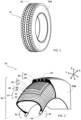
- FIG 1 schematically represents a tire 10 according to the prior art.
- This tire 10 comprises a tread 20 and two sidewalls 30A, 30B (only one of which is shown here), said tread 20 and said sidewalls 30A, 30B covering a carcass 40 (not shown on the figure 1 ).
- FIG 2 details more particularly the carcass 40 of a tire 10 conforming to the prior art.
- This carcass 40 thus comprises a carcass reinforcement 41 made up of coated wires 42 of rubber composition, and two beads 43 each comprising circumferential reinforcing reinforcements 44 (here, rods) which hold the tire 10 on a rim (not shown).
- the carcass reinforcement 41 is anchored in each of the beads 43.
- the carcass 40 further comprises a top reinforcement comprising two working layers 44 and 45. Each of the working layers 44 and 45 is reinforced by reinforcing elements 46 and 47 wires which are parallel in each layer and crossed from one layer to another, making angles of between 10° and 70° with the circumferential direction
- circumferential direction is meant a direction which is tangent to any circle centered on the axis of rotation. This direction is perpendicular to both an axial direction and a radial direction.
- radial direction is meant a direction which is perpendicular to the axis of rotation of the tire (this direction corresponds to the direction of the thickness of the tread at the center of said tread).
- axial direction is meant a direction parallel to the axis of rotation of the tire.
- the tire further comprises a hooping reinforcement 48, arranged radially outside the crown reinforcement.
- This hooping frame 48 is formed of elements of reinforcement 49 oriented circumferentially and spirally wound.
- the tire 10 shown on the figure 2 is a “tubeless” tire. It comprises an inner rubber made of rubber composition impermeable to inflation gas and covering the inner surface of the tire.
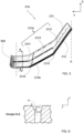
- FIG. 3 is a detailed sectional view of the tread 20 of the figure 2 .
- the tread ensures contact of the tire 10 with the road.
- it comprises blocks 21 of rubber material and notches 22 delimiting said blocks 21.
- the blocks 21 constitute the solid part of the tread 20 and the notches 22 constitute the hollow part of this same tread 20.
- notch we mean different types of cuts, for example grooves, incisions or any other cuts.
- groove we mean a notch whose distance between the walls of material which delimit it is greater than 2 mm and whose depth is greater than or equal to 1 mm.
- cision we mean a cut whose distance between the walls of material which delimit it is less than or equal to 2 mm and whose depth is greater than or equal to 1 mm.
- cuts may include, for example, “barley grains”, i.e. cuts whose depth is less than 1 mm.
- block is meant a raised element delimited by grooves and comprising side walls and a contact face, the latter being intended to come into contact with a ground during rolling.
- rolling surface 23 of tread 20 we mean the surface which brings together all the points of the tire which will come into contact with a ground under usual driving conditions. These points which will come into contact with the ground belong to the contact faces of the blocks 21. On the Figure 3 , the rolling surface 23 is deliberately extended above the notches 22 to ensure its continuity between the two edges 25A and 25B.
- the “usual driving conditions” are the conditions of use defined by the ETRTO (European Tire and Rim Technical Organization) standard. These conditions of use specify the reference inflation pressure corresponding to the load capacity of the tire indicated by its load index and its speed code. These conditions of use may also be called “nominal conditions” or “conditions of use”.
- bottom surface 24 is meant a theoretical surface which passes through the radially interior points of the grooves 221 of the tread 20. It thus delimits the boundary between the tread 20 and the carcass 40 of the tire. This bottom surface 24 extends between a first edge 25A and a second edge 25B of the tread 20.
- edge 25A, 25B of the tread 20 is meant the surfaces delimiting the boundaries between the tread 20 and the sidewalls 30. These two edges 25A, 25B extend radially and they are spaced apart from each other by one value W corresponding to the width of the tread 20. These two edges 25A, 25B are located at the same distance relative to a central axis C. This central axis C divides the tread 20 into two half-treads .
- the tread 20 of the Figure 3 here comprises three grooves 221. These grooves 221 extend circumferentially in the tread forming a volume of notches VE.
- the tread 20 is delimited by a rolling surface 23, a bottom surface 24 and a first edge 25A and a second edge 25B.
- the total volume VT of this tread corresponds to the volume that a rubber material would occupy between these different limits (the rolling surface 23, the bottom surface 24, the edges 25A, 25B) in the theoretical case where this tread would not include any notches.
- VT VE+VC, with VC the volume of rubber actually contained in the tread.
- One way to determine the total volume VT of the tread would be to calculate a total surface area ST of this tread in a radian or meridian plane and to multiply it by the perimeter of the tire. Such a total surface ST is in particular represented in hatching on the Figure 3 . This total surface ST is therefore delimited by the rolling surface 23, the bottom surface 24 and a first edge 25A and a second edge 25B.
- Laser mapping systems have been used to obtain measurement points of point data from a surface of a tire. Such a process is described in particular in the documents WO2015016888 And EP2914946 .
- Laser mapping systems typically include a laser probe used to measure the distance from the probe to the tire tread surface for each point along the tire surface. This laser probe perhaps any suitable device for acquiring data associated with the tread (for example the height of this tread) using a laser, such as a laser probe used in a TMM-570 measuring machine from the company WOLF & BECK . It is then possible to digitally simulate the contours of the rolling surface 23 and the bottom surface 24 by laser scanning.
- the rolling surface 23 is obtained from points measured on the contact faces of the blocks.
- the bottom surface 24 is obtained from points measured in the bottom of the grooves 221.
- the first edge 25A and the second edge 25B are obtained by knowing the width W of the tread. This width W can be obtained by making an inked imprint of the tread under usual driving conditions.
- the simulation of the rolling surface 23, the bottom surface 24 and the determination of the edges 25A, 25B make it possible to calculate the total surface ST of the tread. Said ST surface is presented with hatching on the Figure 3 .
- the perimeter of the tire is obtained by multiplying an average radius of curvature Rc in the median circumferential plane or equatorial plane of this tire by 2 ⁇ ⁇ .
- the average radius of curvature Rc is the radius which originates from the axis of rotation of the tire and which passes through the middle of the surface of the tread. From the total surface area ST and the perimeter of the tire, it is then possible to deduce the total volume VT of the tread.
- the rubber volume VC and the total volume VT make it possible to determine the volumetric notching rate TEV.
- Another method for determining a volumetric notch rate TEV would be to make full use of the possibilities of laser measuring means such as those disclosed in the document FR2996640 .
- These measuring means comprise a beam having an axis directed tangentially to the surface of the central zone of the tread of the tire and/or to the surface of at least one lateral zone of this tread. From these measuring means, different external profiles are produced over the entire circumference of the tire. The superposition of these external profiles on the same meridian makes it possible to determine a peak profile and a bottom profile. It is then possible to construct a total surface limited by the top profile and the bottom profile as well as by planes delimiting the tread.
- planes delimiting the tread are planes normal to the crown profile determining the width of the tread in contact with the ground under nominal load and pressure conditions in accordance with ETRTO.
- a notched surface is constructed limited by the exterior profile, the bottom profile and the planes delimiting the tread.
- volumetric notch rate can also be determined by other methods known to those skilled in the art.
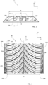
- FIG. 4 is a detailed view of a part of a tread 20 according to the invention.
- the tread 20 is here in new condition. It comprises a plurality of blocks 21A, 21B which extend respectively from one of the edges 25A, 25B of the tread 20 to the central axis C according to a certain curvature.
- the central axis C then comprises an alternation of blocks 21A, 21B having as their origin the edges 25A, 25B of the tread 20.
- the tread 20 is here called directional, that is to say that the blocks 21A , 21B are specifically arranged to optimize the behavioral characteristics according to a predetermined direction of rotation. This direction of rotation is conventionally indicated by an arrow on the side of the tire (arrow noted R on the figure 4 ).
- the blocks have a maximum height at least equal to 5.5 mm and at most equal to 9 mm.
- the maximum height of the blocks is at most equal to 7.5 mm. This maximum height is measured for the blocks at the level of the central axis C. It corresponds to the distance between the rolling surface 23 and the bottom surface 24 at this level.
- the maximum height of a block corresponds to the maximum depth of the grooves which delimit this block.
- the block 21A includes a main incision 211A and a secondary incision 212A. It also includes a first beveled zone 213 and a second beveled zone 214 at two main side walls of the block 21A.
- the main incision 211A begins from one of the sides 30A to the central axis C.
- This main incision 211A is divided into a first incision part 2111, a second incision part 2112 and a third part of incision 2113.
- the first incision part 2111 and the second incision part 2112 are connected together at a first connection point 2114.
- the second incision part 2112 and the third incision part 2113 are connected together at a second connection point 2115.
- the first incision part 2111 thus extends between the sidewall 30A and the first connection point 2114. More particularly, this first incision part 2111 forms a trace rectilinear on the rolling surface between the sidewall 30A and the first connection point 2114. This trace is generally parallel to the direction Y.
- the first incision part 2111 comprises two inclined planes 21111. These inclined planes 21111 form chamfers on the tread 20. The chamfers make it possible to improve grip on dry ground, and more particularly braking on such ground .
- Each inclined plane 21111 extends between a first point A and a second point B.
- the first point A corresponds to the intersection between the inclined plane 21111 and the rolling surface 23 of the tread.
- the second point B corresponds to the intersection between the inclined plane 21111 and a side wall 21112 delimiting the incision 21111.
- the inclined plane 21111 is defined by a height, a width and by an angle of inclination relative to the circumferential direction X.
- the height of the inclined plane corresponds to the distance between the first point A and the second point B in a radial projection, that is to say in a projection on the Z axis.
- the height of the inclined plane is here included between 0.5 and 1mm.
- the width of the inclined plane corresponds to the distance between the first point A and the second point B according to a circumferential projection, that is to say according to a projection on the X axis.
- the width of the inclined plane is here between 1 .5 and 2 mm.
- the angle of inclination of the inclined part is understood between 30 degrees and 50 degrees relative to the circumferential direction a rectilinear trace on the rolling surface between the first connection point 2114 and the second connection point 2115.
- the second incision part 2112 also comprises two planes inclined forming chamfers on the tread 20.
- the third incision part 2113 extends between the second connection point 2115 and one end of the block 21A, close to the central axis C. More particularly, the third part incision 2113 forms a wavy trace on the rolling surface between said second connection point 2115 and the end of the block 21A. This wavy trace extends in a main direction which makes an angle of approximately 45 degrees with the axial direction Y.
- the third incision part 2113 does not include here inclined planes forming chamfers.
- Block 21A also includes a secondary incision 212A.
- This secondary incision 212A forms a rectilinear trace on the rolling surface which cuts the main incision 211A at the level of its second incision part 2112.
- the secondary incision 212A makes an angle of approximately 80 degrees with the axial direction Y
- the main side walls of block 21A also include inclined planes 213 and 214 which form chamfers.
- FIG 7 is a schematic view, at a time T, of a contact area AC with a ground of the tread of the tire of the figure 4 .
- contact area we mean the surface formed by the tire with the ground at this instant T. It is through this contact area that all the mechanical forces between the vehicle and the ground pass. All the contact areas determined at different times make it possible to reconstruct an image of the rolling surface of the tread.
- the contact area here is substantially rectangular with rounded contour portions. This contact area includes both the contact surfaces of the SC blocks (solid surfaces in gray on the Figure 7 ) and the surfaces occupied by the notches (empty surfaces in white on the Figure 7 ).
- This TES surface notch rate illustrates the importance of notches (grooves, incisions) on the running surface of the tread. It is relatively high here due to the presence of a large number of grooves obliques 221 which delimit the blocks 21A, 21B.
- this surface notch rate TES is increased due to the presence of the inclined planes at the level of the main walls of the blocks 21A, 21B and in part of the main incisions 211.
- the surface notch rate TES is greater than or equal to 0.50. Even more preferably, the surface notch rate TES is greater than or equal to 0.55.
- the ratio between the surface notch rate TES and the volume notch rate TEV is at least equal to 1.5 and at most equal to 1.9.
- FIG 8 is a schematic view at a time T, of a contact area AC of the tread of the tire of the figure 4 , but in a certain state of wear.
- the wear of the tread is for example of the order of 2 mm deep.
- the inclined planes at the level of the main walls of the blocks 21A, 21B and the main incisions 211A have disappeared from the tread.
- the oblique grooves 221 then have a smaller width in this contact area AC. Therefore, the surface notch rate TES decreases with wear of the tread.
- the surface notch rate TES of the worn tread at a depth of 2 mm compared to the tread in new condition is at least equal to 0.41 times the surface notch rate TES at l new condition and at most equal to 0.66 times said TES in new condition.
- the surface notch rate TES of the worn tread at 2 mm depth compared to the tread in new condition is at least equal to 0.5 times the TES at l new condition and at most equal to 0.58 times said TES in new condition.
- a volumetric notch rate TEV of the tread of the figure 4 it is possible to determine a volumetric notch rate TEV of the tread of the figure 4 , using the method described in Figure 3 .
- the grooves 221, the incisions 211 and 212 thus form notches in the tread defining a volume of notches VE in said tread.
- the volume notch rate TEV is here at least equal to 0.24 and at most equal to 0.35.
- the volumetric notch rate TEV is at least equal to 0.25.
- the volumetric notch rate TEV is at least equal to 0.26.
- the volumetric notch rate TEV is at least equal to 0.27.
- the volumetric notch rate TEV is at least equal to 0.28.
- the volumetric notch rate TEV is at least equal to 0.29.
- the volumetric notch rate TEV is at least equal to 0.30.
- the volumetric notch rate TEV is at least equal to 0.31.
- the volumetric notch rate TEV is at least equal to 0.32.
- the volumetric notch rate TEV is at least equal to 0.33.
- the volumetric notch rate TEV is at least equal to 0.34.
- FIG. 9 represents part of the contact area of the Figure 7 centered on a first block 21A and on a second block 21B arranged on either side of the central axis C.
- the first block 21A and the second block 21B here form a pattern 26 which is specifically delimited by dotted lines on the Figure 7 .
- the block patterns 26 follow one another in the circumferential direction X in a step P of constant width here.
- pattern we mean a set of blocks which is repeated in the circumferential direction. This repetition can be done in iso-dimension.
- the tread is then called single-pitch. Alternatively, this repetition can be done with different dimensions, in particular different pitch values.
- the tread is then called multi-pitch.
- the number of different pitch values for a multi-pitch tread is between 3 and 5.
- the main incision 211A of the first block 21A extends from the first edge 25A to one end of the first block 21A, near the central axis C.
- This main incision 211A has a projected length lpy1 in the axial direction Y
- the main incision 211B of the second block 21B extends from the second edge 25B to one end of the second block 21B, near the central axis C.
- This main incision 211B has a projected length lpy2 in the axial direction Y.
- the lengths lpy1 and lpy2 here have an identical value corresponding to half the width W of the tread.
- the incision density SD in pattern 26 is here between 10 mm -1 and 70 mm -1 .
- the incision density SD in the pattern 26 is at least equal to 25 mm -1 and at most equal to 50 mm -1 .
- the incision density SD in the pattern 26 is at least equal to 30 mm -1 and at most equal to 40 mm -1 .
- the tread is a multi-pitch tread comprising a first pattern, a second pattern and a third pattern having three different pitches P1, P2, P3.
- first motif a first motif
- second motif a second motif
- Figure 12 illustrates the third motif.
- FIG. 10 thus illustrates a first pattern having a first step P1.
- This first pattern comprises the first block 21A and the second block 21B arranged on either side of the central axis C.
- the main incision 211A of the first block 21A extends from the first edge 25A to one end of the first block 21A, near the central axis C.
- This main incision 211A has a projected length lpy11 in the axial direction Y.
- the main incision 211B of the second block 21B extends from the second edge 25B to at one end of the second block 21B, near the central axis C.
- This main incision 211B has a projected length lpy21 in the axial direction Y.
- the lengths lpy11 and lpy21 here have an identical value corresponding to half the width W of the tread. It is also possible to determine the projected lengths lpy31 and lpy41 of the secondary incisions 211A and 211B of the first block 21A and the second block 21B. From these projected lengths, it is possible to determine an incision density SD1.
- FIG. 11 thus illustrates a second pattern having a second step P2, in which the second step P2 is greater than the first step P1.
- This second pattern comprises the first block 21A and the second block 21B arranged on either side of the central axis C.
- the main incision 211A of the first block 21A extends from the first edge 25A to one end of the first block 21A, near the central axis C.
- This main incision 211A has a projected length lpy12 in the axial direction Y.
- the main incision 211B of the second block 21B extends from the second edge 25B until at one end of the second block 21B, near the central axis C.
- This main incision 211B has a projected length lpy22 in the axial direction Y.
- the lengths lpy12 and lpy22 here have an identical value corresponding to half the width W of the tread. It is also possible to determine the projected lengths lpy32 and lpy42 of the secondary incisions 212A and 212B of the first block 21A and the second block 21B. From these projected lengths, it is possible to determine an incision density SD2.
- FIG. 12 illustrates a third pattern having a third pitch P3, in which the third pitch P3 is greater than the second pitch P2.
- This third pattern comprises the first block 21A and the second block 21B arranged on either side of the central axis C.
- the main incision 211A of the first block 21A extends from the first edge 25A to one end of the first block 21A, near the central axis C.
- This main incision 211A has a projected length lpy13 in the axial direction Y.
- the main incision 211B of the second block 21B extends from the second edge 25B to at one end of the second block 21B, near the central axis C.
- This main incision 211B has a projected length lpy23 in the axial direction Y.
- the lengths lpy13 and lpy23 here have an identical value corresponding to the half the width W of the tread. It is also possible to determine the projected lengths lpy33 and lpy43 of the secondary incisions 212A and 212B of the first block 21A and the second block 21B. From these projected lengths, it is possible to determine an incision density SD3.
- the tread comprises an arrangement of N1 P1 pitch patterns, N2 P2 pitch patterns and N3 P3 pitch patterns. It is thus possible to determine an average incision density SDmoy corresponding to the average of the incision densities SD1, SD2, SD3 of the pitch patterns P1, P2, P3 over the entire circumference of the tread.
- SDavg SD 1 ⁇ NOT 1 ⁇ P 1 + SD 2 ⁇ NOT 2 ⁇ P 2 + SD 3 ⁇ NOT 3 ⁇ P 3 NOT 1 ⁇ P 1 + NOT 2 ⁇ P 2 + NOT 3 ⁇ P 3 .
- the pitch patterns P1, P2, P3 are arranged randomly on the tread in order to limit the emergence of noise from the tire while rolling.
- the arrangement between pitch patterns P1, P2 and P3 could be as follows: P1 P1 P2 P1 P2 P2 P2 P2 P1 P1 P2 P1 P1 P1 P2 P2 P3 P2 P2 P3 P2 P1 P2 P2 P1 P1 P1 P1 P2 P1 P1 P1 P1 P2 P1 P1 P1 P1 P2 P1 P1 P1 P2 P2 P3 P3 P3 P2 P2 P3 P3 P3 P3 P3 P3 P3 P3 P3 P2 P2 P1 P2 P2 P3 P2 P1 P2 P2 P1 P2 P2 P1 P1 P2 P2 P1 P1 P1 P2 P3 P2 P1 P1 P1 P2 P3 P2 P1.
- Such an arrangement would then include 21 P1 step patterns, 35 P2 step patterns and 13 P3 step patterns.
- a pitch P is determined as the distance between the centers of two adjacent oblique grooves framing a block.
- these are measured in groups of patterns belonging to the same type of pattern, for example in groups of patterns P1 P1 P1, P2 P2 P2 and P3 P3 P3 .
- the average incision density SDmoy is at least equal to 25 mm -1 and at most equal to 50 mm -1 .
- the average incision density SDmoy is at least equal to 30 mm -1 and at most equal to 40 mm -1 .
- each block is formed from a rubber material.
- the composition of this rubber material has a glass transition temperature of between -40°C and -10°C, and preferably between -35°C and -15°C and a shear modulus measured at 60°C between 0.5 MPa and 2 MPa, and preferably between 0.7 MPa and 1.5 MPa.
- the SBR solution of this preferred embodiment is a copolymer of styrene and butadiene prepared in solution. It has the characteristic of carrying a silanol function and an amine function.
- the silanol function of the SBR solution carrying a silanol function and an amine function can for example be introduced by hydrosilylation of the elastomer chain with a silane carrying an alkoxysilane group, followed by hydrolysis of the alkoxysilane function to a silanol function.
- the silanol function of the SBR solution carrying a silanol function and an amine function can also be introduced by reaction of the living elastomer chains with a cyclic polysiloxane compound as described in EP 0 778 311
- the amine function of the SBR solution carrying a silanol function and an amine function can for example be introduced by initiating the polymerization with an initiator carrying such a function.
- An SBR solution carrying a silanol function and an amine function can also be prepared by reaction of living elastomer chains with a compound carrying an alkoxysilane function and an amine function according to the procedure described in the patent application.
- the silanol function and the amine function are preferentially located inside the chain of the SBR solution, outside the chain ends.
- the hydrolysis reaction of the alkoxysilane function carried by the SBR solution in silanol function can be carried out according to the procedure described in the patent application EP 2 266 819 A1 or by a step of stripping the solution containing the SBR solution.
- the amine function can be a primary, secondary or tertiary, preferably tertiary, amine.
- the blocks 21 A, 21B are presented as being continuous from one edge of the tread 25A, 25B towards the central axis C.
- the blocks can be discontinuous.
- blocks can be interrupted by one or more grooves.
- the groove(s) may have an orientation substantially equal to the orientation of the secondary incisions 212.
Description
La présente invention concerne un pneumatique pour véhicule automobile dit pneumatique « quatre saisons ». L'invention est plus particulièrement adaptée pour un pneumatique destiné à équiper un véhicule de tourisme ou une camionnette.The present invention relates to a tire for a motor vehicle called a “four-season” tire. The invention is more particularly suitable for a tire intended to equip a passenger vehicle or a van.
De manière connue, un pneumatique dit quatre saisons est un pneumatique qui présente un excellent compromis d'adhérence sur sol enneigé/sol mouillé tout en préservant les performances sur sol sec. Ces pneumatiques ont pour objectif de rouler en sécurité toute l'année quelle que soit la météo. Ils ont généralement reçu la certification hiver 3PMSF (pour 3 Peak Mountain Snow Flake) attestant de leurs excellentes performances sur sol enneigé et sur sol mouillé. Cette certification est notamment indiquée sur l'un ou les deux flancs de ces types de pneumatiques.As is known, a so-called four-season tire is a tire which presents an excellent compromise of grip on snowy ground/wet ground while preserving performance on dry ground. These tires aim to drive safely all year round whatever the weather. They have generally received the 3PMSF winter certification (for 3 Peak Mountain Snow Flake) attesting to their excellent performance on snowy and wet surfaces. This certification is notably indicated on one or both sidewalls of these types of tires.
Le document
On trouve un pneumatique tel que décrit précédemment dans le document
Il existe un besoin constant d'améliorer les performances des pneumatiques quatre saisons tant sur le compromis d'adhérence entre un sol enneigé et un sol mouillé que pour l'adhérence sur sol sec et plus particulièrement l'adhérence en freinage sur sol sec.There is a constant need to improve the performance of all-season tires both in terms of the grip compromise between snow-covered ground and wet ground as well as for grip on dry ground and more particularly grip when braking on dry ground.
La présente invention vise à remédier au moins en partie à ce besoin.The present invention aims to remedy this need at least in part.
Plus particulièrement, la présente invention vise à améliorer le compromis d'adhérence sur sol enneigé/sol mouillé pour un pneumatique quatre saisons tout en améliorant les performances d'adhérence sur sol sec.More particularly, the present invention aims to improve the grip compromise on snowy ground/wet ground for a four-season tire while improving the grip performance on dry ground.
L'invention concerne un pneumatique comportant une bande de roulement.The invention relates to a tire comprising a tread.
Par « pneumatique », on entend tous les types de bandage en matériau caoutchoutique soumis en roulage à une pression interne ou non soumis à une telle pression interne en roulage (c'est le cas d'un bandage sans air comprimé, par exemple, de type Tweel™).By “pneumatic”, we mean all types of tire made of rubber material subjected to internal pressure during rolling or not subjected to such internal pressure during rolling (this is the case of a tire without compressed air, for example, of type Tweel ™ ).
Plus particulièrement, l'invention concerne un pneumatique comportant une bande de roulement directionnelle de largeur W. Cette bande de roulement a un certain volume total VT et une pluralité d'entailles définissant un volume d'entailles VE dans ladite bande de roulement. Le rapport entre le volume d'entailles VE sur le volume total VT détermine un taux d'entaillement volumique TEV tel que TEV=VE/VT. Pour une bande de roulement à l'état neuf, le taux d'entaillement volumique TEV est au moins égal à 0,29 et au plus égal à 0,35. Une partie de la pluralité des entailles délimitent des blocs en matériau caoutchoutique. Ces blocs sont organisés dans des motifs de blocs de pas P qui se succèdent selon la direction circonférentielle. Le pas P n'est pas forcément constant et il peut prendre des valeurs différentes dans la circonférence du pneumatique. Une partie de la pluralité des entailles forme une ou plusieurs incisions dans un des motifs selon une densité d'incision SD. Cette densité d'incision SD correspond au rapport entre une somme de la/des longueur(s) projetée(s) de la/des incision(s) selon une direction axiale sur le produit du pas P du motif et de la largeur W de la bande de roulement, l'ensemble étant multiplié par 1000 tel que ![]()
![]()
La combinaison de ces caractéristiques permet d'obtenir un pneumatique présentant un excellent compromis d'adhérence entre un sol enneigé et un sol mouillé tout en améliorant les performances d'adhérence sur un sol sec.The combination of these characteristics makes it possible to obtain a tire presenting an excellent grip compromise between snowy ground and wet ground while improving grip performance on dry ground.
Préférentiellement, le taux d'entaillement volumique TEV est au moins égal à 0,32.Preferably, the volumetric notch rate TEV is at least equal to 0.32.
La bande de roulement forme une aire de contact AC avec le sol. Les blocs de la bande de roulement contenus dans l'aire de contact AC forment une surface de contact SC. Le rapport entre la différence entre ladite aire de contact AC et la surface de contact SC et ladite aire de contact AC détermine un taux d'entaillement surfacique TES de la bande de roulement, avec TES=(AC-SC)/AC. Dans un mode de réalisation préférentiel, pour la bande de roulement à l'état neuf, le taux d'entaillement surfacique TES est au moins égal à 0,40 et au plus égal à 0,70.The tread forms an AC contact area with the ground. The tread blocks contained in the contact area AC form a contact surface SC. The report between the difference between said contact area AC and the contact surface SC and said contact area AC determines a surface notch rate TES of the tread, with TES=(AC-SC)/AC. In a preferred embodiment, for the tread in new condition, the surface notch rate TES is at least equal to 0.40 and at most equal to 0.70.
Préférentiellement, le taux d'entaillement surfacique TES est supérieur ou égal à 0,50.Preferably, the surface notch rate TES is greater than or equal to 0.50.
Préférentiellement, le taux d'entaillement surfacique TES est supérieur ou égal à 0,55.Preferably, the surface notch rate TES is greater than or equal to 0.55.
Dans un mode de réalisation préférentiel, le rapport TES/TEV entre le taux d'entaillement surfacique TES sur le taux d'entaillement volumique TEV est au moins égal à 1,5 et au plus égal à 1,9.In a preferred embodiment, the TES/TEV ratio between the surface notch rate TES on the volume notch rate TEV is at least equal to 1.5 and at most equal to 1.9.
Dans une variante de réalisation, la bande de roulement comprend différents types de motifs Mj, avec j supérieur ou égal à 2, les motifs appartenant à un même type de motif ayant un même pas, les pas entre des motifs appartenant respectivement à deux types de motifs différents étant différents, et en ce que la densité moyenne d'incision SDmoy sur toute la circonférence du pneumatique est au moins égale à 10 mm-1 et au plus égale à 70 mm-1, ladite densité moyenne d'incisions SDmoy correspondant à la moyenne des densités d'incisions SDj des motifs des différents types de motifs Mj de pas Pj sur toute la circonférence de la bande de roulement, ladite densité moyenne d'incisions SDmoy étant pondérée en fonction du nombre de motifs Nj par type de motif Mj et du pas Pj des motifs appartenant au type de motif Mj sur ladite circonférence de la bande de roulement, tel que 
Préférentiellement, la densité d'incision SD ou la densité moyenne d'incision SDmoy est au moins égale à 25 mm-1.Preferably, the incision density SD or the average incision density SDmoy is at least equal to 25 mm -1 .
Préférentiellement, la densité d'incision SD ou la densité moyenne d'incision SDmoy est au moins égale à 30 mm-1.Preferably, the incision density SD or the average incision density SDmoy is at least equal to 30 mm -1 .
Préférentiellement, la densité d'incision SD ou la densité moyenne d'incision SDmoy est au moins égale à 35 mm-1.Preferably, the incision density SD or the average incision density SDmoy is at least equal to 35 mm -1 .
Préférentiellement, la densité d'incision SD ou la densité moyenne d'incision SDmoy est au moins égale à 40 mm-1.Preferably, the incision density SD or the average incision density SDmoy is at least equal to 40 mm -1 .
Préférentiellement, la densité d'incision SD ou la densité moyenne d'incision SDmoy est au moins égale à 45 mm-1.Preferably, the incision density SD or the average incision density SDmoy is at least equal to 45 mm -1 .
Préférentiellement, la densité d'incision SD ou la densité moyenne d'incision SDmoy est au plus égale à 60 mm-1.Preferably, the incision density SD or the average incision density SDmoy is at most equal to 60 mm -1 .
Préférentiellement, la densité d'incision SD ou la densité moyenne d'incision SDmoy est au plus égale à 50 mm-1.Preferably, the incision density SD or the average incision density SDmoy is at most equal to 50 mm -1 .
Dans un mode de réalisation préférentiel, dans la bande de roulement à l'état neuf, les blocs ont une hauteur maximale au moins égale à 5,5 mm et au plus égale à 9 mm, et de préférence au plus égale à 7,5 mm. En diminuant la hauteur radiale du bloc, on améliore globalement la résistance au roulement du pneumatique ainsi que le comportement routier sur sol sec.In a preferred embodiment, in the tread in new condition, the blocks have a maximum height at least equal to 5.5 mm and at most equal to 9 mm, and preferably at most equal to 7.5 mm. By reducing the radial height of the block, the rolling resistance of the tire as well as the road behavior on dry ground is generally improved.
Les blocs sont en matériau caoutchoutique.The blocks are made of rubber material.
Par « matériau caoutchoutique », on entend un matériau polymérique de type mélange élastomérique, c'est-à-dire un matériau polymérique obtenu par mélangeage d'au moins un élastomère, d'au moins une charge renforçante et d'un système de réticulation.By “rubber material” is meant a polymeric material of the elastomeric mixture type, that is to say a polymeric material obtained by mixing at least one elastomer, at least one reinforcing filler and a crosslinking system. .
Une caractéristique physique usuelle d'un mélange élastomérique est sa température de transition vitreuse Tg, température à laquelle le mélange élastomérique passe d'un état caoutchouteux déformable à un état vitreux rigide. La température de transition vitreuse Tg d'un mélange élastomérique est généralement déterminée lors de la mesure des propriétés dynamiques du mélange élastomérique, sur un viscoanalyseur (Metravib VA4000), selon la norme ASTM D 5992-96. La mesure des propriétés dynamiques est réalisée sur un échantillon de mélange élastomérique vulcanisé, c'est-à-dire cuit jusqu'à un taux de conversion d'au moins 90%, l'échantillon ayant la forme d'une éprouvette cylindrique ayant une épaisseur égale à 2 mm et une section égale à 78,5 mm2. On enregistre la réponse de l'échantillon de mélange élastomérique à une sollicitation sinusoïdale en cisaillement simple alterné, ayant une amplitude crête-crête égale à 0,7 MPa et une fréquence égale à 10 Hz. On effectue un balayage en température à vitesse de montée en température constante de +1.5°C/min. Les résultats exploités sont généralement le module complexe de cisaillement dynamique G*, comprenant une partie élastique G' et une partie visqueuse G", et la perte dynamique tgδ, égale au rapport G"/G'. La température de transition vitreuse Tg est la température à laquelle la perte dynamique tgδ atteint un maximum lors du balayage en température. La valeur de G* mesurée à 60°C est représentative de la rigidité du matériau caoutchoutique, c'est-à-dire de sa résistance à la déformation élastique.A usual physical characteristic of an elastomeric mixture is its glass transition temperature Tg, the temperature at which the elastomeric mixture goes from a deformable rubbery state to a rigid glassy state. The glass transition temperature Tg of an elastomeric mixture is generally determined when measuring the dynamic properties of the elastomeric mixture, on a viscoanalyzer (Metravib VA4000), according to standard ASTM D 5992-96. The measurement of dynamic properties is carried out on a sample of vulcanized elastomeric mixture, that is to say cooked to a conversion rate of at least 90%, the sample having the shape of a cylindrical test tube having a thickness equal to 2 mm and a section equal to 78.5 mm 2 . The response of the elastomeric mixture sample to a sinusoidal stress in alternating simple shear is recorded, having a peak-peak amplitude equal to 0.7 MPa and a frequency equal to 10 Hz. A temperature scan is carried out at rising speed. at constant temperature of +1.5°C/min. The results used are generally the complex dynamic shear module G*, comprising an elastic part G' and a viscous part G", and the dynamic loss tgδ, equal to the ratio G"/G'. The glass transition temperature Tg is the temperature at which the dynamic loss tgδ reaches a maximum during the temperature sweep. The value of G* measured at 60°C is representative of the rigidity of the rubber material, that is to say its resistance to elastic deformation.
Dans un mode de réalisation préférentiel, la composition du matériau caoutchoutique des blocs du motif a une température de transition vitreuse Tg comprise entre -40°C et -10°C et préférentiellement entre -35°C et -15°C. De plus la composition du matériau caoutchoutique a un module de cisaillement dynamique mesuré à 60°C comprise entre 0,5 MPa et 2 Mpa, et préférentiellement entre 0,7 Mpa et 1,5 Mpa.In a preferred embodiment, the composition of the rubber material of the blocks of the pattern has a glass transition temperature Tg of between -40°C and -10°C and preferably between -35°C and -15°C. In addition, the composition of the rubber material has a dynamic shear modulus measured at 60°C of between 0.5 MPa and 2 MPa, and preferably between 0.7 MPa and 1.5 MPa.
Au niveau de la composition chimique, le mélange élastomérique du ou des blocs selon l'invention comprend 100 pce (parties pour cent élastomère) d'une matrice élastomère comprenant un élastomère diénique modifié. Par définition, un élastomère diénique est un homopolymère ou un copolymère, issu aux moins en partie des monomères diènes, c'est-à-dire des monomères porteurs de deux doubles liaisons carbone-carbone conjuguées ou non. Préférentiellement, le mélange élastomérique comprend l'élastomère diénique modifié à un taux au moins égal à 20 pce.In terms of chemical composition, the elastomeric mixture of the block(s) according to the invention comprises 100 phr (parts per hundred elastomer) of an elastomeric matrix comprising a modified diene elastomer. By definition, a diene elastomer is a homopolymer or a copolymer, derived at least in part from diene monomers, that is to say monomers carrying two carbon-carbon double bonds, conjugated or not. Preferably, the elastomeric mixture comprises the modified diene elastomer at a level at least equal to 20 phr.
L'élastomère diénique modifié selon l'invention comprend au moins un groupe fonctionnel comprenant un atome de silicium, ce dernier se situant au sein de la chaîne principale, y compris les extrémités de chaîne. L'expression « atome se situant au sein de la chaîne principale de l'élastomère, y compris les extrémités de chaîne », s'entend ici comme n'étant pas un atome pendant (ou latéral) le long de la chaîne principale de l'élastomère mais étant un atome intégré à la chaîne principale. Dans un mode de réalisation préférentiel, la composition du bloc comprend un mélange élastomérique, ledit mélange élastomérique comportant un élastomère diénique modifié comprenant au moins un groupe fonctionnel comprenant un atome de silicium, ce dernier se situant au sein de la chaîne principale de l'élastomère y compris les extrémités de chaîne.The modified diene elastomer according to the invention comprises at least one functional group comprising a silicon atom, the latter being located within the main chain, including the chain ends. The expression "atom located within the main chain of the elastomer, including the chain ends", is understood here as not being a pendant (or lateral) atom along the main chain of the elastomer. elastomer but being an atom integrated into the main chain. In a preferred embodiment, the composition of the block comprises an elastomeric mixture, said elastomeric mixture comprising a modified diene elastomer comprising at least one functional group comprising a silicon atom, the latter located within the main chain of the elastomer including chain ends.
Préférentiellement, l'élastomère diénique modifié comprend un groupe fonctionnel comprenant un atome de silicium en une extrémité de la chaîne principale de l'élastomère.Preferably, the modified diene elastomer comprises a functional group comprising a silicon atom at one end of the main chain of the elastomer.
Préférentiellement, le groupe fonctionnel comprend une fonction silanol. En variante, l'atome de silicium du groupe fonctionnel est substitué par au moins une fonction alcoxy, éventuellement totalement ou partiellement hydrolysée en hydroxyle.Preferably, the functional group comprises a silanol function. Alternatively, the silicon atom of the functional group is substituted by at least one alkoxy function, optionally totally or partially hydrolyzed to hydroxyl.
Dans une variante de réalisation, le groupe fonctionnel se situe dans la chaîne élastomère principale, on dira alors que l'élastomère diénique est couplé ou encore fonctionnalisé en milieu de chaîne. L'atome de silicium du groupe fonctionnel lie alors les deux branches de la chaîne principale de l'élastomère diénique. L'atome de silicium du groupe fonctionnel est substitué par au moins une fonction alcoxy, éventuellement totalement ou partiellement hydrolysée en hydroxyle.In a variant embodiment, the functional group is located in the main elastomer chain, we will then say that the diene elastomer is coupled or even functionalized in the middle of the chain. The silicon atom of the functional group then bonds the two branches of the main chain of the diene elastomer. The silicon atom of the functional group is substituted by at least one alkoxy function, optionally totally or partially hydrolyzed to hydroxyl.
Selon les variantes de l'invention selon lesquelles le groupe fonctionnel comprend une fonction silanol en extrémité de chaîne, le groupement fonctionnel peut être une fonction silanol ou encore un groupement polysiloxane ayant une extrémité silanol. Des élastomères diéniques modifiés correspondant sont décrits notamment dans les documents
Selon l'une quelconque des variantes de l'invention selon lesquelles l'atome de silicium du groupe fonctionnel est substitué par au moins une fonction alcoxy, éventuellement totalement ou partielle hydrolysée en hydroxyle, l'atome de silicium peut également être substitué, directement ou par l'intermédiaire d'un radical hydrocarboné divalent, par au moins une autre fonction comprenant au moins un hétéroatome choisi parmi N, S, O, P. De préférence, l'atome de silicium est substitué par au moins une autre fonction par l'intermédiaire d'un radical hydrocarboné divalent, plus préférentiellement aliphatique linéaire en C1- C18. On peut, à titre d'exemple, citer parmi ces autres fonctions, les amines primaires, secondaires ou tertiaires, cycliques ou non, les isocyanates, les imines, les cyano, les thiols, les carboxylates, les époxydes, les phosphines primaires, secondaires ou tertiaires. L'autre fonction est de préférence une amine tertiaire, plus préférentiellement un groupement diéthylamino- ou diméthylamino-. La fonction alcoxy est de préférence méthoxy, éthoxy, butoxy ou propoxy. Des élastomères diéniques modifiés correspondant à ces variantes sont décrits notamment dans les documents
La modification de l'élastomère diénique par au moins un groupe fonctionnel comprenant un atome de silicium, n'exclut pas une autre modification de l'élastomère par exemple en extrémité de chaîne par une fonction amine introduite lors de l'initiation de la polymérisation, tel que décrit dans
Préférentiellement, l'élastomère diénique modifié selon l'invention est un polymère de 1,3-butadiène, plus préférentiellement un copolymère de 1,3-butadiène et de styrène (SBR).Preferably, the modified diene elastomer according to the invention is a polymer of 1,3-butadiene, more preferably a copolymer of 1,3-butadiene and styrene (SBR).
L'élastomère diénique modifié selon l'invention peut être, selon différentes variantes, utilisé seul dans le mélange élastomérique ou en coupage avec au moins un autre élastomère diénique conventionnellement utilisé en pneumatique, qu'il soit étoilé, couplé, fonctionnalisé par exemple à l'étain ou au silicium, ou non.The modified diene elastomer according to the invention can be, according to different variants, used alone in the elastomeric mixture or in blending with at least one other diene elastomer conventionally used in tires, whether it is star-shaped, coupled, functionalized for example with tin or silicon, or not.
Egalement du point de vue de sa composition chimique, le mélange élastomérique de la bande de roulement selon l'invention comprend une résine plastifiante de type résine thermoplastique à un taux au moins égal à 20 pce.Also from the point of view of its chemical composition, the elastomeric mixture of the tread according to the invention comprises a plasticizing resin of the thermoplastic resin type at a level at least equal to 20 phr.
Dans une variante de réalisation de l'invention, le pneumatique a une certification hiver 3PMSF, ladite certification étant indiquée sur un flanc du pneumatique.In a variant embodiment of the invention, the tire has a 3PMSF winter certification, said certification being indicated on one sidewall of the tire.
La présente invention sera mieux comprise à la lecture de la description détaillée de modes de réalisation pris à titre d'exemples nullement limitatifs et illustrés par les dessins annexés sur lesquels :
- La
figure 1 est une vue schématique en perspective d'un pneumatique selon l'art antérieur ; - La
figure 2 est vue schématique en perspective d'une coupe partielle d'un pneumatique selon un autre art antérieur ; - La
figure 3 est une vue en coupe de la bande de roulement du pneumatique de lafigure 2 ; - La
figure 4 est une vue de détail partielle d'une bande de roulement à l'état neuf d'un pneumatique conforme à un premier mode de réalisation de l'invention ; - La
figure 5 est une vue agrandie d'un bloc de la bande de roulement de lafigure 4 ; - La
figure 6 est une vue en coupe selon un plan de coupe A-A du bloc de lafigure 5 ; - La
figure 7 est une vue schématique d'une aire de contact de la bande de roulement à l'état neuf du pneumatique de lafigure 4 ; - La
figure 8 est une vue schématique d'une aire de contact de la bande de roulement à l'état usé du pneumatique de lafigure 4 ; - La
figure 9 est une partie de l'aire de contact de lafigure 7 centrée sur un motif de la bande de roulement ; - La
figure 10 est une vue agrandie d'un ensemble de blocs appartenant à un motif de pas P1 d'une bande de roulement d'un pneumatique conforme à un second mode de réalisation de l'invention ; - La
figure 11 est une vue agrandie d'un ensemble de blocs appartenant à un motif de pas P2 d'une bande de roulement d'un pneumatique conforme au second mode de réalisation de l'invention ; - La
figure 12 est une vue agrandie d'un ensemble de blocs appartenant à un motif de pas P3 d'une bande de roulement d'un pneumatique conforme au second mode de réalisation de l'invention.
- There
figure 1 is a schematic perspective view of a tire according to the prior art; - There
figure 2 is a schematic perspective view of a partial section of a tire according to another prior art; - There
Figure 3 is a sectional view of the tire tread of thefigure 2 ; - There
Figure 4 is a partial detail view of a tread in new condition of a tire conforming to a first embodiment of the invention; - There
Figure 5 is an enlarged view of a tread block of theFigure 4 ; - There
Figure 6 is a sectional view according to a section plane AA of the block of theFigure 5 ; - There
Figure 7 is a schematic view of a contact area of the tread in the new condition of the tire of theFigure 4 ; - There
figure 8 is a schematic view of a contact area of the tread in the worn state of the tire of thefigure 4 ; - There
Figure 9 is part of the contact area of theFigure 7 centered on a tread pattern; - There
Figure 10 is an enlarged view of a set of blocks belonging to a pitch pattern P1 of a tread of a tire conforming to a second embodiment of the invention; - There
Figure 11 is an enlarged view of a set of blocks belonging to a pitch pattern P2 of a tread of a tire conforming to the second embodiment of the invention; - There
Figure 12 is an enlarged view of a set of blocks belonging to a pitch pattern P3 of a tread of a tire conforming to the second embodiment of the invention.
L'invention n'est pas limitée aux modes de réalisation et variantes présentées et d'autres modes de réalisation et variantes apparaîtront clairement à l'homme du métier sans sortir du cadre défini par les revendications ci-jointes.The invention is not limited to the embodiments and variants presented and other embodiments and variants will be clearly apparent to those skilled in the art without departing from the scope defined by the attached claims.
Sur les différentes figures, les éléments identiques ou similaires portent les mêmes références. C'est ainsi que les références utilisées pour identifier des éléments sur la bande de roulement sont reprises pour identifier ces mêmes éléments sur l'aire de contact réalisée à partir de ladite bande de roulement.In the different figures, identical or similar elements bear the same references. This is how the references used to identify elements on the tread are used to identify these same elements on the contact area made from said tread.
La
Par « direction circonférentielle », on entend une direction qui est tangente à tout cercle centré sur l'axe de rotation. Cette direction est perpendiculaire à la fois à une direction axiale et à une direction radiale.By “circumferential direction” is meant a direction which is tangent to any circle centered on the axis of rotation. This direction is perpendicular to both an axial direction and a radial direction.
Par « direction radiale », on entend une direction qui est perpendiculaire à l'axe de rotation du pneumatique (cette direction correspond à la direction de l'épaisseur de la bande de roulement au centre de ladite bande de roulement).By “radial direction” is meant a direction which is perpendicular to the axis of rotation of the tire (this direction corresponds to the direction of the thickness of the tread at the center of said tread).
Par « direction axiale », on entend une direction parallèle à l'axe de rotation du pneumatique.By “axial direction” is meant a direction parallel to the axis of rotation of the tire.
Le pneumatique comporte en outre une armature de frettage 48, disposée radialement à l'extérieur de l'armature de sommet. Cette armature de frettage 48 est formée d'éléments de renforcement 49 orientés circonférentiellement et enroulés en spirale. Le pneumatique 10 représenté sur la
La
Par « entaille », on entend différents types de découpures, par exemple des rainures, des incisions ou toutes autres découpures.By “notch” we mean different types of cuts, for example grooves, incisions or any other cuts.
Par « rainure », on entend une entaille dont la distance entre les parois de matière qui la délimitent est supérieure à 2 mm et dont la profondeur est supérieure ou égale à 1 mm.By “groove” we mean a notch whose distance between the walls of material which delimit it is greater than 2 mm and whose depth is greater than or equal to 1 mm.
Par « incision », on entend une entaille dont la distance entre les parois de matière qui la délimitent est inférieure ou égale à 2 mm et dont la profondeur est supérieure ou égale à 1 mm.By “incision”, we mean a cut whose distance between the walls of material which delimit it is less than or equal to 2 mm and whose depth is greater than or equal to 1 mm.
Les autres types de découpures peuvent comprendre, par exemple, des « grains d'orge », c'est à dire des entailles dont la profondeur est inférieure à 1 mm.Other types of cuts may include, for example, “barley grains”, i.e. cuts whose depth is less than 1 mm.
Par « bloc », on entend un élément en relief délimité par des rainures et comprenant des parois latérales et une face de contact, cette dernière étant destinée à venir en contact avec un sol pendant le roulage.By “block” is meant a raised element delimited by grooves and comprising side walls and a contact face, the latter being intended to come into contact with a ground during rolling.
Par « surface de roulement » 23 de bande de roulement 20, on entend la surface qui regroupe l'ensemble des points du pneumatique qui vont entrer en contact avec un sol dans des conditions usuelles de roulage. Ces points qui vont entrer en contact avec le sol appartiennent aux faces de contact des blocs 21. Sur la
Par « surface de fond » 24, on entend une surface théorique qui passe par les points radialement intérieurs des rainures 221 de la bande de roulement 20. Elle délimite ainsi la frontière entre la bande de roulement 20 et la carcasse 40 du pneumatique. Cette surface de fond 24 s'étend entre un premier bord 25A et un second bord 25B de la bande de roulement 20.By “bottom surface” 24 is meant a theoretical surface which passes through the radially interior points of the
Par « bord » 25A, 25B de la bande de roulement 20 on entend les surfaces délimitant les frontières entre la bande de roulement 20 et les flancs 30. Ces deux bords 25A, 25B s'étendent radialement et ils sont distants entre eux d'une valeur W correspondant à la largeur de la bande de roulement 20. Ces deux bords 25A, 25B sont situés à une même distance par rapport à un axe central C. Cet axe central C divise la bande de roulement 20 en deux demi-bandes de roulement.By “edge” 25A, 25B of the
La bande de roulement 20 de la
La bande de roulement 20 est délimitée par une surface de roulement 23, une surface de fond 24 et un premier bord 25A et un second bord 25B. Le volume total VT de cette bande de roulement correspond au volume qu'occuperait un matériau caoutchoutique entre ces différentes limites (la surface de roulement 23, la surface de fond 24, les bords 25A, 25B) dans le cas théorique où cette bande de roulement ne comprendrait aucune entaille. Ainsi, on a la relation suivante VT= VE+VC, avec VC le volume de caoutchouc contenu réellement dans la bande de roulement. The
Un moyen de déterminer le volume total VT de la bande de roulement serait de calculer une surface totale ST de cette bande dans un plan radian ou méridien et de la multiplier par le périmètre du pneumatique. Une telle surface totale ST est notamment représentée en hachures sur la
On connaît des systèmes pour obtenir des données de surface de la bande de roulement afin de déterminer la carte de cette surface de bande de roulement. Par exemple, des systèmes de cartographie laser ont été utilisés pour obtenir des points de mesure de données de points d'une surface d'un pneumatique. Un tel procédé est notamment décrit dans les documents
Le périmètre du pneumatique est obtenu en multipliant un rayon moyen de courbure Rc dans le plan circonférentiel médian ou plan équatorial de ce pneumatique par 2∗π. Le rayon moyen de courbure Rc est le rayon qui a pour origine l'axe de rotation du pneumatique et qui passe par le milieu de la surface de la bande de roulement. A partir de la surface totale ST et du périmètre du pneumatique, il est alors possible de déduire le volume total VT de la bande de roulement.The perimeter of the tire is obtained by multiplying an average radius of curvature Rc in the median circumferential plane or equatorial plane of this tire by 2 ∗ π. The average radius of curvature Rc is the radius which originates from the axis of rotation of the tire and which passes through the middle of the surface of the tread. From the total surface area ST and the perimeter of the tire, it is then possible to deduce the total volume VT of the tread.
Le taux d'entaillement volumique TEV correspond au rapport du volume d'entaille VE sur le volume total VT, tel que TEV=VE/VT. Or étant donné que VE= VT-VC, on peut déduire la relation TEV=1-(VC/VT). Le volume de gomme VC contenu dans la bande de roulement peut être déterminé de la manière suivante :
- on pèse le pneumatique à l'état neuf ;
- on vient ensuite raboter ce pneumatique jusqu'à atteindre l'usure maximale, c'est-à-dire jusqu'à atteindre la surface de fond 24 ;
- on pèse le pneumatique raboté ;
- la différence de masse entre le pneumatique à l'état neuf et le pneumatique à l'état usé donne la masse de matériau caoutchoutique réellement contenue dans la bande de roulement ;
- on détermine le volume de gomme VC à partir de la masse de matériau caoutchoutique contenue dans la bande de roulement et de la masse volumique de ce matériau caoutchoutique.
- we weigh the tire when new;
- this tire is then planed until maximum wear is reached, that is to say until the
bottom surface 24 is reached; - we weigh the planed tire;
- the difference in mass between the tire in the new state and the tire in the worn state gives the mass of rubber material actually contained in the tread;
- the volume of rubber VC is determined from the mass of rubber material contained in the tread and the density of this rubber material.
Le volume de gomme VC et le volume total VT permettent de déterminer le taux d'entaillement volumique TEV.The rubber volume VC and the total volume VT make it possible to determine the volumetric notching rate TEV.
Une autre méthode pour déterminer un taux d'entaillement volumique TEV serait d'utiliser pleinement les possibilités des moyens de mesure par laser tels que ceux divulgués dans le document
On définit une grandeur TEMeridienn correspondant à un taux d'entaillement méridien dans un plan méridien n, avec ![]()
![]()
![]()
![]()
On peut également déterminer le taux d'entaillement volumique par d'autres méthodes connues de l'homme du métier.The volumetric notch rate can also be determined by other methods known to those skilled in the art.
La
La
L'incision principale 211A débute à partir d'un des flancs 30A jusqu'à l'axe central C. Cette incision principale 211A est divisée en une première partie d'incision 2111, une seconde partie d'incision 2112 et une troisième partie d'incision 2113. La première partie d'incision 2111 et la seconde partie d'incision 2112 sont reliées entre elles au niveau d'un premier point de liaison 2114. La seconde partie d'incision 2112 et la troisième partie d'incision 2113 sont reliées entre elles au niveau d'un second point de liaison 2115. La première partie d'incision 2111 s'étend ainsi entre le flanc 30A et le premier point de liaison 2114. Plus particulièrement, cette première partie d'incision 2111 forme une trace rectiligne sur la surface de roulement entre le flanc 30A et le premier point de liaison 2114. Cette trace est globalement parallèle à la direction Y. Comme il est illustré à la
La
La différence entre l'aire de contact AC et la surface de contact SC des blocs permet de déterminer un taux d'entaillement surfacique TES de la bande de roulement, avec TES=(AC-SC)/AC , dans lequel le taux d'entaillement surfacique TES est au moins égal à 0,40 et au plus égal à 0,70 pour ladite bande de roulement. Ce taux d'entaillement surfacique TES illustre l'importance des entailles (rainures, incisions) sur la surface de roulement de la bande de roulement. Il est ici relativement élevé du fait de la présence d'un grand nombre de rainures obliques 221 qui délimitent les blocs 21A, 21B. De plus, ce taux d'entaillement surfacique TES est augmenté du fait de la présence des plans inclinés au niveau des parois principales des blocs 21A, 21B et dans une partie des incisions principales 211. Les plans inclinés sur la bande de roulement à l'état neuf limitent ainsi les surfaces de contact des blocs 21A, 21B. Dans un mode de réalisation préférentiel, le taux d'entaillement surfacique TES est supérieur ou égal à 0,50. Encore plus préférentiellement, le taux d'entaillement surfacique TES est supérieur ou égal à 0,55.The difference between the contact area AC and the contact surface SC of the blocks makes it possible to determine a surface notch rate TES of the tread, with TES=(AC-SC)/AC, in which the rate of surface notch TES is at least equal to 0.40 and at most equal to 0.70 for said tread. This TES surface notch rate illustrates the importance of notches (grooves, incisions) on the running surface of the tread. It is relatively high here due to the presence of a large number of
Dans un autre mode de réalisation préférentiel, le rapport entre le taux d'entaillement surfacique TES sur le taux d'entaillement volumique TEV est au moins égal à 1,5 et au plus égal à 1,9.In another preferred embodiment, the ratio between the surface notch rate TES and the volume notch rate TEV is at least equal to 1.5 and at most equal to 1.9.
La
Il est possible de déterminer un taux d'entaillement volumique TEV de la bande de roulement de la
Dans un mode de réalisation préférentiel, le taux d'entaillement volumique TEV est au moins égal à 0,25.In a preferred embodiment, the volumetric notch rate TEV is at least equal to 0.25.
Dans un mode de réalisation préférentiel, le taux d'entaillement volumique TEV est au moins égal à 0,26.In a preferred embodiment, the volumetric notch rate TEV is at least equal to 0.26.
Dans un mode de réalisation préférentiel, le taux d'entaillement volumique TEV est au moins égal à 0,27.In a preferred embodiment, the volumetric notch rate TEV is at least equal to 0.27.
Dans un mode de réalisation préférentiel, le taux d'entaillement volumique TEV est au moins égal à 0,28.In a preferred embodiment, the volumetric notch rate TEV is at least equal to 0.28.
Dans un mode de réalisation préférentiel, le taux d'entaillement volumique TEV est au moins égal à 0,29.In a preferred embodiment, the volumetric notch rate TEV is at least equal to 0.29.
Dans un mode de réalisation préférentiel, le taux d'entaillement volumique TEV est au moins égal à 0,30.In a preferred embodiment, the volumetric notch rate TEV is at least equal to 0.30.
Dans un mode de réalisation préférentiel, le taux d'entaillement volumique TEV est au moins égal à 0,31.In a preferred embodiment, the volumetric notch rate TEV is at least equal to 0.31.
Dans un mode de réalisation préférentiel, le taux d'entaillement volumique TEV est au moins égal à 0,32.In a preferred embodiment, the volumetric notch rate TEV is at least equal to 0.32.
Dans un mode de réalisation préférentiel, le taux d'entaillement volumique TEV est au moins égal à 0,33.In a preferred embodiment, the volumetric notch rate TEV is at least equal to 0.33.
Dans un mode de réalisation préférentiel, le taux d'entaillement volumique TEV est au moins égal à 0,34.In a preferred embodiment, the volumetric notch rate TEV is at least equal to 0.34.
C'est le concepteur du pneumatique qui a le choix du taux d'entaillement volumique en fonction du compromis d'adhérence recherché entre une adhérence sur un sol enneigé et/ou une adhérence sur sol humide et/ou une adhérence sur sol sec.It is the tire designer who has the choice of the volume notch rate depending on the grip compromise sought between grip on snow-covered ground and/or grip on wet ground and/or grip on dry ground.
La
Sur la 
Dans un autre mode de réalisation, la bande de roulement est une bande de roulement multipas comprenant un premier motif, un second motif et un troisième motif présentant trois pas P1, P2, P3 différents. La
La ![]()
![]()
La ![]()
![]()
La ![]()
![]()
Dans le mode de réalisation des ![]()
![]()
Les motifs de pas P1, P2, P3 sont arrangés de manière aléatoire sur la bande de roulement afin de limiter l'émergence d'un bruit du pneumatique en roulage. Ainsi pour un pneumatique de dimension 205/55 R 16, l'arrangement entre motifs de pas P1, P2 etP3 pourrait être le suivant : P1 P1 P2 P1 P2 P2 P2 P2 P1 P1 P2 P1 P1 P1 P2 P2 P3 P2 P2 P3 P2 P1 P2 P2 P1 P1 P1 P1 P2 P1 P2 P1 P1 P1 P1 P2 P1 P1 P2 P2 P3 P3 P3 P2 P2 P3 P3 P3 P3 P3 P2 P2 P1 P2 P2 P3 P2 P1 P2 P2 P1 P2 P3 P2 P2 P1 P2 P2 P2 P1 P1 P1 P2 P3 P2 P1. Un tel arrangement comporterait alors 21 motifs de pas P1, 35 motifs de pas P2 et 13 motifs de pas P3. Comme il a déjà été précisé, un pas P est déterminé comme la distance entre les centres de deux rainures obliques adjacentes encadrant un bloc. Afin de déterminer avec précision les valeurs des pas P1, P2 et P3, ceux-ci sont mesurés dans des groupes de motifs appartenant à un même type de motif par exemple dans des groupes de motifs P1 P1 P1, P2 P2 P2 et P3 P3 P3.The pitch patterns P1, P2, P3 are arranged randomly on the tread in order to limit the emergence of noise from the tire while rolling. Thus for a tire of size 205/55 R 16, the arrangement between pitch patterns P1, P2 and P3 could be as follows: P1 P1 P2 P1 P2 P2 P2 P2 P1 P1 P2 P1 P1 P1 P2 P2 P3 P2 P2 P3 P2 P1 P2 P2 P1 P1 P1 P1 P2 P1 P2 P1 P1 P1 P1 P2 P1 P1 P2 P2 P3 P3 P3 P2 P2 P3 P3 P3 P3 P3 P2 P2 P1 P2 P2 P3 P2 P1 P2 P2 P1 P2 P3 P2 P2 P1 P2 P2 P2 P1 P1 P1 P2 P3 P2 P1. Such an arrangement would then include 21 P1 step patterns, 35 P2 step patterns and 13 P3 step patterns. As has already been specified, a pitch P is determined as the distance between the centers of two adjacent oblique grooves framing a block. In order to precisely determine the values of the steps P1, P2 and P3, these are measured in groups of patterns belonging to the same type of pattern, for example in groups of patterns P1 P1 P1, P2 P2 P2 and P3 P3 P3 .
Ainsi avec un tel arrangement entre les motifs, il est possible de déterminer une valeur de densité moyenne d'incision SDmoy sur toute la circonférence du pneumatique comprise entre 10 mm-1 et 70 mm-1. Dans un mode de réalisation préférentiel, la densité moyenne d'incision SDmoy est au moins égale à 25 mm-1 et au plus égale à 50 mm-1. Préférentiellement, la densité moyenne d'incision SDmoy est au moins égale à 30 mm-1 et au plus égale à 40 mm-1.Thus with such an arrangement between the patterns, it is possible to determine an average incision density value SDmoy over the entire circumference of the tire of between 10 mm -1 and 70 mm -1 . In a preferred embodiment, the average incision density SDmoy is at least equal to 25 mm -1 and at most equal to 50 mm -1 . Preferably, the average incision density SDmoy is at least equal to 30 mm -1 and at most equal to 40 mm -1 .
Pour l'ensemble des modes de réalisation illustrés aux
Dans un mode de réalisation préférentiel, la composition du matériau caoutchoutique des blocs est à base d'au moins :
- une matrice élastomère comprenant plus de 50% en masse d'un SBR solution qui porte une fonction silanol et une fonction amine ;
- 20 à 200 pce d'au moins une silice ;
- un agent de couplage pour coupler la silice au SBR solution ;
- 10 à 100 pce d'une résine hydrocarbonée présentant une Tg supérieure à 20°C ;
- 15 à 50 pce d'un plastifiant liquide.
- an elastomeric matrix comprising more than 50% by weight of an SBR solution which carries a silanol function and an amine function;
- 20 to 200 phr of at least one silica;
- a coupling agent for coupling the silica to the SBR solution;
- 10 to 100 phr of a hydrocarbon resin having a Tg greater than 20°C;
- 15 to 50 phr of a liquid plasticizer.
Le SBR solution de ce mode de réalisation préférentiel est un copolymère de styrène et de butadiène préparé en solution. Il a pour caractéristique de porter une fonction silanol et une fonction amine. La fonction silanol du SBR solution portant une fonction silanol et une fonction amine peut par exemple être introduite par hydrosilylation de la chaîne élastomère par un silane portant un groupement alcoxysilane, suivie d'une hydrolyse de la fonction alcoxysilane en fonction silanol. La fonction silanol du SBR solution portant une fonction silanol et une fonction amine peut également être introduite par réaction des chaînes élastomères vivantes avec un composé polysiloxane cyclique tel que décrit dans
L'invention n'est pas limitée aux modes de réalisation et variantes présentées et d'autres modes de réalisation et variantes apparaîtront clairement à l'homme du métier sans sortir du cadre défini par les revendications ci-jointes.The invention is not limited to the embodiments and variants presented and other embodiments and variants will be clearly apparent to those skilled in the art without departing from the scope defined by the attached claims.
Ainsi, sur la
Claims (19)
- Tyre comprising a directional tread (10) of width W, said tread (10) having a total volume VT, said tread comprising a plurality of voids (221, 211, 212) defining a voids volume VE in said tread, the ratio of the voids volume VE to the total volume determining a volumetric voids ratio TEV such that TEV=VE/VT, part of the plurality of voids (211) delimiting blocks (21A, 21B) of rubbery material, said blocks (21A, 21B) being organized into patterns (26) of blocks of pitch P succeeding one another in the circumferential direction (X), part of the plurality of voids forming one or more sipes (211, 212) in one of the patterns at a sipes density SD, said sipes density SD corresponding to the ratio of a sum of the projected length(s) (lpyi) of the sipe(s) (211, 212) in an axial direction (Y) to the product of the pitch P of the pattern and the width (W) of the tread, all multiplied by 1000, such that
 - the sipes density SD in a pattern of pitch P is comprised between 10 mm-1 and 70 mm-1;- the volumetric voids ratio TEV is at least equal to 0.29 and at most equal to 0.35.
 - Tyre according to Claim 1, wherein the volumetric voids ratio TEV is at least equal to 0.32.
- Tyre according to either one of Claims 1 or 2, said tread forming a contact patch AC in which the tyre is in contact with the ground, a part of the blocks (21A, 21B) of the tread forming a contact surface SC via which the blocks are in contact with said ground in said contact patch AC, the ratio of the difference between said contact patch AC and the contact surface SC of the blocks to the contact patch AC determining a surface voids ratio TES of the tread, where TES=(AC-SC)/AC, wherein the surface voids ratio TES is at least equal to 0.40 and at most equal to 0.70 for said tread when new.
- Tyre according to Claim 3, wherein said surface voids ratio TES is greater than or equal to 0.50.
- Tyre according to either one of Claims 3 or 4, wherein said surface voids ratio TES is greater than or equal to 0.55.
- Tyre according to Claim 3, wherein the ratio TES/TEV of said surface voids ratio TES to said volumetric voids ratio TEV is at least equal to 1.5 and at most equal to 1.9.
- Tyre according to any one of Claims 1 to 6, wherein the tread comprises different pattern types Mj, where j is greater than or equal to 2, the patterns belonging to the one same pattern type having the one same pitch, the pitch between patterns belonging to two different respective pattern types being different, and wherein the mean sipes density SDmean over the entire circumference of the tyre is comprised between 10 mm-1 and 70 mm-1, said mean sipes density SDmean corresponding to the mean of the sipes densities SDj of the patterns of the different pattern types Mj of pitch Pj over the entire circumference of the tread, said mean sipes density SDmean being weighted according to the number of patterns Nj per pattern type Mj and according to the pitch Pj of the patterns belonging to that pattern type Mj over said circumference of the tread, such that

- Tyre according to Claim 7, wherein the sipes density SD or the mean sipes density SDmean is at least equal to 25 mm-1 and at most equal to 50 mm-1.
- Tyre according to Claim 7, wherein the sipes density SD or the mean sipes density SDmean is at least equal to 30 mm-1 and at most equal to 40 mm-1.
- Tyre according to any one of Claims 1 to 9, wherein, in the tread when new, the blocks (21A, 21B) have a maximum height at least equal to 5.5 mm and at most equal to 9 mm, and preferably at most equal to 7.5 mm.
- Tyre according to any one of Claims 1 to 10, wherein the composition of the rubbery material of the blocks has a glass transition temperature Tg comprised between -40°C and -10°C and preferably between -35°C and -15°C and a complex dynamic shear modulus G* measured at 60°C comprised between 0.5 MPa and 2 MPa, and preferably between 0.7 MPa and 1.5 MPa.
- Tyre according to any one of Claims 1 to 11, wherein the composition of the rubbery material of the blocks comprises an elastomer compound, said elastomer compound containing a modified diene elastomer containing at least one functional group comprising a silicon atom, the latter being situated within the main chain of the elastomer, including the ends of the chain.
- Tyre according to Claim 12, wherein the modified diene elastomer comprises a functional group containing a silicon atom at one end of the main chain of the elastomer.
- Tyre according to Claim 13, wherein the functional group contains a silanol function.
- Tyre according to Claim 14, wherein the functional group is selected from a silanol functionor a polysiloxane group having a silanol end.
- Tyre according to Claim 12, wherein the modified diene elastomer of the elastomeric compound that makes up the block comprises a functional group containing a silicon atom in the middle of the chain.
- Tyre according to Claim 12 or Claim 16, wherein the silicon atom of the functional group is substituted by at least one alkoxy function which may potentially have been fully or partially hydrolysed to hydroxyl.
- Tyre according to Claim 16, wherein the silicon atom of the functional group is substituted directly or via a divalent hydrocarbon radical, by at least one other functional group containing at least one heteroatom selected from N, S, O, P.
- Tyre according to any one of Claims 1 to 17, wherein said tyre has a 3PMSF winter certification, said certification being indicated on a sidewall (30A, 30B) of the tyre, that is to say "Three Peak Mountain Snowflake", said certification being indicated on a sidewall (30A, 30B) of the tire, attesting to its excellent performance on snowy ground and on wet ground.
Applications Claiming Priority (2)
| Application Number | Priority Date | Filing Date | Title |
|---|---|---|---|
| FR1912461 | 2019-11-06 | ||
| PCT/FR2020/052019 WO2021089959A1 (en) | 2019-11-06 | 2020-11-06 | Tire comprising a tread |
Publications (2)
| Publication Number | Publication Date |
|---|---|
| EP4054863A1 EP4054863A1 (en) | 2022-09-14 |
| EP4054863B1 true EP4054863B1 (en) | 2023-09-13 |
Family
ID=73699148
Family Applications (1)
| Application Number | Title | Priority Date | Filing Date |
|---|---|---|---|
| EP20819813.5A Active EP4054863B1 (en) | 2019-11-06 | 2020-11-06 | Tire comprising a tread |
Country Status (4)
| Country | Link |
|---|---|
| US (1) | US20220388346A1 (en) |
| EP (1) | EP4054863B1 (en) |
| CN (1) | CN114599529B (en) |
| WO (1) | WO2021089959A1 (en) |
Families Citing this family (1)
| Publication number | Priority date | Publication date | Assignee | Title |
|---|---|---|---|---|
| JP2023092234A (en) * | 2021-12-21 | 2023-07-03 | 住友ゴム工業株式会社 | tire |
Family Cites Families (23)
| Publication number | Priority date | Publication date | Assignee | Title |
|---|---|---|---|---|
| FR2740778A1 (en) | 1995-11-07 | 1997-05-09 | Michelin & Cie | SILICA-BASED RUBBER COMPOSITION AND FUNCTIONALIZED DIENE POLYMER HAVING TERMINAL SILANOL FUNCTION |
| CN102026826B (en) | 2008-03-10 | 2015-01-14 | 株式会社普利司通 | Method for producing modified conjugated diene polymer/copolymer, modified conjugated diene polymer/copolymer, and rubber composition and tier using the same |
| FR2930554B1 (en) | 2008-04-29 | 2012-08-17 | Michelin Soc Tech | ELASTOMERIC MIXTURE COMPRISING MAJORITARILY AN AMINO-ALCOXYSILANE GROUP-COUPLED DIENE ELASTOMER, RUBBER COMPOSITION COMPRISING SAME AND METHODS OF OBTAINING SAME |
| FR2951178B1 (en) | 2009-10-08 | 2012-08-17 | Michelin Soc Tech | FUNCTIONALIZED DIENIC ELASTOMER AND RUBBER COMPOSITION CONTAINING SAME. |
| FR2964600B1 (en) * | 2010-09-09 | 2014-08-22 | Michelin Soc Tech | TIRE TREAD FOR TIRES |
| FR2968600A1 (en) * | 2010-12-08 | 2012-06-15 | Michelin Soc Tech | TIRE TREAD FOR SNOW TIRES |
| RU2561179C1 (en) * | 2011-08-31 | 2015-08-27 | Мишлен Решерш Э Текник С.А. | Tire tread with better grip of snow or dry road pavement |
| FR2993500B1 (en) * | 2012-07-20 | 2015-02-06 | Michelin & Cie | TREAD TIRE FOR HEAVY-DUTY AND TIRE ENGINE AXLE TIRES |
| FR2996640B1 (en) | 2012-10-09 | 2015-11-13 | Michelin & Cie | METHOD FOR MEASURING THE WEAR OF THE TIRE TREAD OF A TIRE |
| EP2914946B1 (en) | 2012-10-31 | 2019-03-27 | Compagnie Générale des Etablissements Michelin | System and method for analyzing tire tread parameters |
| KR101759511B1 (en) | 2013-07-31 | 2017-07-19 | 미쉐린 러쉐르슈 에 떼크니크 에스.에이. | System and method for analyzing tire tread parameters |
| FR3009559A1 (en) | 2013-08-08 | 2015-02-13 | Michelin & Cie | MODIFIED DIENIC ELASTOMER, PROCESS FOR THE SYNTHESIS, AND RUBBER COMPOSITION COMPRISING SAME |
| FR3009558B1 (en) | 2013-08-09 | 2015-09-04 | Michelin & Cie | COUPLED DIENIC ELASTOMER HAVING SILANOL FUNCTION IN THE CHAIN AND FUNCTIONALIZING AMINE IN THE END OF THE CHAIN AND RUBBER COMPOSITION COMPRISING SAME |
| FR3009557B1 (en) | 2013-08-09 | 2015-09-11 | Michelin & Cie | MODIFIED DIENOUS ELASTOMER COMPRISING A DIAMOND ELASTOMER COUPLED BY AN AMINOALCOXYSILANE COMPOUND AND FUNCTIONALIZED AMINE IN CHAIN END AND RUBBER COMPOSITION COMPRISING SAME |
| FR3012767B1 (en) * | 2013-11-05 | 2015-10-23 | Michelin & Cie | ROLLER BAND COMPRISING A BLOCK HAVING A PLURALITY OF INCISIONS |
| USD758286S1 (en) * | 2014-05-09 | 2016-06-07 | Compagnie Generale Des Etablissements | Tire tread |
| FR3033142B1 (en) | 2015-02-27 | 2017-02-24 | Michelin & Cie | PNEUMATIC WITH DIRECTIONAL ROLLER WITH ALTERNATE BLOCKS AND CURVED GROOVES |
| FR3033144B1 (en) * | 2015-02-27 | 2017-02-24 | Michelin & Cie | PNEUMATIC WITH DIRECTIONAL BEARING BAND COMPRISING CURVED BLOCKS WITH INCISIONS |
| USD818939S1 (en) * | 2016-11-10 | 2018-05-29 | Compagnie Generale Des Etablissements Michelin | Tire tread |
| USD825445S1 (en) * | 2016-11-10 | 2018-08-14 | Compagnie Generale Des Etablissements Michelin | Tire tread |
| DE102017203221A1 (en) * | 2017-02-28 | 2018-08-30 | Continental Reifen Deutschland Gmbh | Vehicle tires |
| CA182497S (en) * | 2018-06-01 | 2019-04-23 | Michelin & Cie | Pneumatic tyre |
| CN110239285B (en) * | 2019-05-09 | 2021-05-25 | 正新橡胶(中国)有限公司 | Pneumatic tire |
-
2020
- 2020-11-06 CN CN202080074753.0A patent/CN114599529B/en active Active
- 2020-11-06 WO PCT/FR2020/052019 patent/WO2021089959A1/en unknown
- 2020-11-06 EP EP20819813.5A patent/EP4054863B1/en active Active
- 2020-11-06 US US17/774,970 patent/US20220388346A1/en active Pending
Also Published As
| Publication number | Publication date |
|---|---|
| EP4054863A1 (en) | 2022-09-14 |
| CN114599529A (en) | 2022-06-07 |
| CN114599529B (en) | 2023-11-03 |
| US20220388346A1 (en) | 2022-12-08 |
| WO2021089959A1 (en) | 2021-05-14 |
Similar Documents
| Publication | Publication Date | Title |
|---|---|---|
| EP4054860A1 (en) | Tire comprising a tread | |
| WO2021089958A1 (en) | Tyre having a tread | |
| EP4054859B1 (en) | Tyre comprising a tread | |
| EP4054863B1 (en) | Tire comprising a tread | |
| EP4054864B1 (en) | Tire comprising a tread | |
| EP4054858A1 (en) | Tire comprising a tread | |
| EP4003757B1 (en) | Tyre comprising a tread | |
| EP4003761B1 (en) | Tyre comprising a tread | |
| EP4126565B1 (en) | Tyre having a tread optimized in terms of grip on dry ground | |
| EP4126566B1 (en) | Tyre comprising a tread optimized for grip on snow-covered ground | |
| EP3994013B1 (en) | Tyre comprising a tread | |
| WO2023117478A1 (en) | Tyre having a compromise in terms of performance between grip on snow and running noise | |
| WO2021260335A1 (en) | Tyre comprising a tread optimised for grip on wet ground in the worn condition |
Legal Events
| Date | Code | Title | Description |
|---|---|---|---|
| STAA | Information on the status of an ep patent application or granted ep patent |
Free format text: STATUS: UNKNOWN |
|
| STAA | Information on the status of an ep patent application or granted ep patent |
Free format text: STATUS: THE INTERNATIONAL PUBLICATION HAS BEEN MADE |
|
| PUAI | Public reference made under article 153(3) epc to a published international application that has entered the european phase |
Free format text: ORIGINAL CODE: 0009012 |
|
| STAA | Information on the status of an ep patent application or granted ep patent |
Free format text: STATUS: REQUEST FOR EXAMINATION WAS MADE |
|
| 17P | Request for examination filed |
Effective date: 20220607 |
|
| AK | Designated contracting states |
Kind code of ref document: A1 Designated state(s): AL AT BE BG CH CY CZ DE DK EE ES FI FR GB GR HR HU IE IS IT LI LT LU LV MC MK MT NL NO PL PT RO RS SE SI SK SM TR |
|
| DAV | Request for validation of the european patent (deleted) | ||
| DAX | Request for extension of the european patent (deleted) | ||
| GRAP | Despatch of communication of intention to grant a patent |
Free format text: ORIGINAL CODE: EPIDOSNIGR1 |
|
| STAA | Information on the status of an ep patent application or granted ep patent |
Free format text: STATUS: GRANT OF PATENT IS INTENDED |
|
| INTG | Intention to grant announced |
Effective date: 20230525 |
|
| GRAS | Grant fee paid |
Free format text: ORIGINAL CODE: EPIDOSNIGR3 |
|
| GRAA | (expected) grant |
Free format text: ORIGINAL CODE: 0009210 |
|
| STAA | Information on the status of an ep patent application or granted ep patent |
Free format text: STATUS: THE PATENT HAS BEEN GRANTED |
|
| AK | Designated contracting states |
Kind code of ref document: B1 Designated state(s): AL AT BE BG CH CY CZ DE DK EE ES FI FR GB GR HR HU IE IS IT LI LT LU LV MC MK MT NL NO PL PT RO RS SE SI SK SM TR |
|
| REG | Reference to a national code |
Ref country code: CH Ref legal event code: EP |
|
| REG | Reference to a national code |
Ref country code: DE Ref legal event code: R096 Ref document number: 602020017760 Country of ref document: DE |
|
| REG | Reference to a national code |
Ref country code: IE Ref legal event code: FG4D Free format text: LANGUAGE OF EP DOCUMENT: FRENCH |
|
| REG | Reference to a national code |
Ref country code: LT Ref legal event code: MG9D |
|
| REG | Reference to a national code |
Ref country code: NL Ref legal event code: MP Effective date: 20230913 |
|
| PG25 | Lapsed in a contracting state [announced via postgrant information from national office to epo] |
Ref country code: GR Free format text: LAPSE BECAUSE OF FAILURE TO SUBMIT A TRANSLATION OF THE DESCRIPTION OR TO PAY THE FEE WITHIN THE PRESCRIBED TIME-LIMIT Effective date: 20231214 |
|
| PG25 | Lapsed in a contracting state [announced via postgrant information from national office to epo] |
Ref country code: SE Free format text: LAPSE BECAUSE OF FAILURE TO SUBMIT A TRANSLATION OF THE DESCRIPTION OR TO PAY THE FEE WITHIN THE PRESCRIBED TIME-LIMIT Effective date: 20230913 Ref country code: RS Free format text: LAPSE BECAUSE OF FAILURE TO SUBMIT A TRANSLATION OF THE DESCRIPTION OR TO PAY THE FEE WITHIN THE PRESCRIBED TIME-LIMIT Effective date: 20230913 Ref country code: NO Free format text: LAPSE BECAUSE OF FAILURE TO SUBMIT A TRANSLATION OF THE DESCRIPTION OR TO PAY THE FEE WITHIN THE PRESCRIBED TIME-LIMIT Effective date: 20231213 Ref country code: LV Free format text: LAPSE BECAUSE OF FAILURE TO SUBMIT A TRANSLATION OF THE DESCRIPTION OR TO PAY THE FEE WITHIN THE PRESCRIBED TIME-LIMIT Effective date: 20230913 Ref country code: LT Free format text: LAPSE BECAUSE OF FAILURE TO SUBMIT A TRANSLATION OF THE DESCRIPTION OR TO PAY THE FEE WITHIN THE PRESCRIBED TIME-LIMIT Effective date: 20230913 Ref country code: HR Free format text: LAPSE BECAUSE OF FAILURE TO SUBMIT A TRANSLATION OF THE DESCRIPTION OR TO PAY THE FEE WITHIN THE PRESCRIBED TIME-LIMIT Effective date: 20230913 Ref country code: GR Free format text: LAPSE BECAUSE OF FAILURE TO SUBMIT A TRANSLATION OF THE DESCRIPTION OR TO PAY THE FEE WITHIN THE PRESCRIBED TIME-LIMIT Effective date: 20231214 Ref country code: FI Free format text: LAPSE BECAUSE OF FAILURE TO SUBMIT A TRANSLATION OF THE DESCRIPTION OR TO PAY THE FEE WITHIN THE PRESCRIBED TIME-LIMIT Effective date: 20230913 |
|
| PGFP | Annual fee paid to national office [announced via postgrant information from national office to epo] |
Ref country code: FR Payment date: 20231120 Year of fee payment: 4 Ref country code: DE Payment date: 20231121 Year of fee payment: 4 |
|
| REG | Reference to a national code |
Ref country code: AT Ref legal event code: MK05 Ref document number: 1610908 Country of ref document: AT Kind code of ref document: T Effective date: 20230913 |
|
| PG25 | Lapsed in a contracting state [announced via postgrant information from national office to epo] |
Ref country code: NL Free format text: LAPSE BECAUSE OF FAILURE TO SUBMIT A TRANSLATION OF THE DESCRIPTION OR TO PAY THE FEE WITHIN THE PRESCRIBED TIME-LIMIT Effective date: 20230913 |
|
| PG25 | Lapsed in a contracting state [announced via postgrant information from national office to epo] |
Ref country code: IS Free format text: LAPSE BECAUSE OF FAILURE TO SUBMIT A TRANSLATION OF THE DESCRIPTION OR TO PAY THE FEE WITHIN THE PRESCRIBED TIME-LIMIT Effective date: 20240113 |