EP4003607B1 - Dispensing assembly with a lateral actuating device for a fluid product dispenser - Google Patents
Dispensing assembly with a lateral actuating device for a fluid product dispenser Download PDFInfo
- Publication number
- EP4003607B1 EP4003607B1 EP20757378.3A EP20757378A EP4003607B1 EP 4003607 B1 EP4003607 B1 EP 4003607B1 EP 20757378 A EP20757378 A EP 20757378A EP 4003607 B1 EP4003607 B1 EP 4003607B1
- Authority
- EP
- European Patent Office
- Prior art keywords
- dispensing
- reservoir
- actuation
- assembly according
- lateral
- Prior art date
- Legal status (The legal status is an assumption and is not a legal conclusion. Google has not performed a legal analysis and makes no representation as to the accuracy of the status listed.)
- Active
Links
- 239000012530 fluid Substances 0.000 title claims description 20
- 230000001681 protective effect Effects 0.000 claims description 7
- 230000000694 effects Effects 0.000 claims description 4
- 239000007922 nasal spray Substances 0.000 description 3
- 229940097496 nasal spray Drugs 0.000 description 3
- 208000027418 Wounds and injury Diseases 0.000 description 2
- 230000006378 damage Effects 0.000 description 2
- 238000006073 displacement reaction Methods 0.000 description 2
- 208000014674 injury Diseases 0.000 description 2
- 239000000825 pharmaceutical preparation Substances 0.000 description 2
- 229940127557 pharmaceutical product Drugs 0.000 description 2
- 238000003780 insertion Methods 0.000 description 1
- 230000037431 insertion Effects 0.000 description 1
- 238000004519 manufacturing process Methods 0.000 description 1
- 238000012986 modification Methods 0.000 description 1
- 230000004048 modification Effects 0.000 description 1
- 238000005507 spraying Methods 0.000 description 1
Images

Classifications
-
- A—HUMAN NECESSITIES
- A61—MEDICAL OR VETERINARY SCIENCE; HYGIENE
- A61M—DEVICES FOR INTRODUCING MEDIA INTO, OR ONTO, THE BODY; DEVICES FOR TRANSDUCING BODY MEDIA OR FOR TAKING MEDIA FROM THE BODY; DEVICES FOR PRODUCING OR ENDING SLEEP OR STUPOR
- A61M11/00—Sprayers or atomisers specially adapted for therapeutic purposes
- A61M11/006—Sprayers or atomisers specially adapted for therapeutic purposes operated by applying mechanical pressure to the liquid to be sprayed or atomised
- A61M11/007—Syringe-type or piston-type sprayers or atomisers
-
- B—PERFORMING OPERATIONS; TRANSPORTING
- B05—SPRAYING OR ATOMISING IN GENERAL; APPLYING FLUENT MATERIALS TO SURFACES, IN GENERAL
- B05B—SPRAYING APPARATUS; ATOMISING APPARATUS; NOZZLES
- B05B11/00—Single-unit hand-held apparatus in which flow of contents is produced by the muscular force of the operator at the moment of use
- B05B11/0005—Components or details
- B05B11/0027—Means for neutralising the actuation of the sprayer ; Means for preventing access to the sprayer actuation means
- B05B11/0032—Manually actuated means located downstream the discharge nozzle for closing or covering it, e.g. shutters
-
- A—HUMAN NECESSITIES
- A61—MEDICAL OR VETERINARY SCIENCE; HYGIENE
- A61M—DEVICES FOR INTRODUCING MEDIA INTO, OR ONTO, THE BODY; DEVICES FOR TRANSDUCING BODY MEDIA OR FOR TAKING MEDIA FROM THE BODY; DEVICES FOR PRODUCING OR ENDING SLEEP OR STUPOR
- A61M11/00—Sprayers or atomisers specially adapted for therapeutic purposes
-
- A—HUMAN NECESSITIES
- A61—MEDICAL OR VETERINARY SCIENCE; HYGIENE
- A61M—DEVICES FOR INTRODUCING MEDIA INTO, OR ONTO, THE BODY; DEVICES FOR TRANSDUCING BODY MEDIA OR FOR TAKING MEDIA FROM THE BODY; DEVICES FOR PRODUCING OR ENDING SLEEP OR STUPOR
- A61M15/00—Inhalators
- A61M15/0001—Details of inhalators; Constructional features thereof
- A61M15/0021—Mouthpieces therefor
- A61M15/0025—Mouthpieces therefor with caps
-
- A—HUMAN NECESSITIES
- A61—MEDICAL OR VETERINARY SCIENCE; HYGIENE
- A61M—DEVICES FOR INTRODUCING MEDIA INTO, OR ONTO, THE BODY; DEVICES FOR TRANSDUCING BODY MEDIA OR FOR TAKING MEDIA FROM THE BODY; DEVICES FOR PRODUCING OR ENDING SLEEP OR STUPOR
- A61M15/00—Inhalators
- A61M15/08—Inhaling devices inserted into the nose
-
- A—HUMAN NECESSITIES
- A61—MEDICAL OR VETERINARY SCIENCE; HYGIENE
- A61M—DEVICES FOR INTRODUCING MEDIA INTO, OR ONTO, THE BODY; DEVICES FOR TRANSDUCING BODY MEDIA OR FOR TAKING MEDIA FROM THE BODY; DEVICES FOR PRODUCING OR ENDING SLEEP OR STUPOR
- A61M31/00—Devices for introducing or retaining media, e.g. remedies, in cavities of the body
-
- B—PERFORMING OPERATIONS; TRANSPORTING
- B05—SPRAYING OR ATOMISING IN GENERAL; APPLYING FLUENT MATERIALS TO SURFACES, IN GENERAL
- B05B—SPRAYING APPARATUS; ATOMISING APPARATUS; NOZZLES
- B05B11/00—Single-unit hand-held apparatus in which flow of contents is produced by the muscular force of the operator at the moment of use
- B05B11/01—Single-unit hand-held apparatus in which flow of contents is produced by the muscular force of the operator at the moment of use characterised by the means producing the flow
- B05B11/10—Pump arrangements for transferring the contents from the container to a pump chamber by a sucking effect and forcing the contents out through the dispensing nozzle
- B05B11/1042—Components or details
- B05B11/1052—Actuation means
- B05B11/1056—Actuation means comprising rotatable or articulated levers
- B05B11/1057—Triggers, i.e. actuation means consisting of a single lever having one end rotating or pivoting around an axis or a hinge fixedly attached to the container, and another end directly actuated by the user
-
- B—PERFORMING OPERATIONS; TRANSPORTING
- B05—SPRAYING OR ATOMISING IN GENERAL; APPLYING FLUENT MATERIALS TO SURFACES, IN GENERAL
- B05B—SPRAYING APPARATUS; ATOMISING APPARATUS; NOZZLES
- B05B11/00—Single-unit hand-held apparatus in which flow of contents is produced by the muscular force of the operator at the moment of use
- B05B11/01—Single-unit hand-held apparatus in which flow of contents is produced by the muscular force of the operator at the moment of use characterised by the means producing the flow
- B05B11/10—Pump arrangements for transferring the contents from the container to a pump chamber by a sucking effect and forcing the contents out through the dispensing nozzle
- B05B11/1042—Components or details
- B05B11/1059—Means for locking a pump or its actuation means in a fixed position
-
- A—HUMAN NECESSITIES
- A61—MEDICAL OR VETERINARY SCIENCE; HYGIENE
- A61M—DEVICES FOR INTRODUCING MEDIA INTO, OR ONTO, THE BODY; DEVICES FOR TRANSDUCING BODY MEDIA OR FOR TAKING MEDIA FROM THE BODY; DEVICES FOR PRODUCING OR ENDING SLEEP OR STUPOR
- A61M15/00—Inhalators
- A61M15/009—Inhalators using medicine packages with incorporated spraying means, e.g. aerosol cans
-
- A—HUMAN NECESSITIES
- A61—MEDICAL OR VETERINARY SCIENCE; HYGIENE
- A61M—DEVICES FOR INTRODUCING MEDIA INTO, OR ONTO, THE BODY; DEVICES FOR TRANSDUCING BODY MEDIA OR FOR TAKING MEDIA FROM THE BODY; DEVICES FOR PRODUCING OR ENDING SLEEP OR STUPOR
- A61M2205/00—General characteristics of the apparatus
- A61M2205/27—General characteristics of the apparatus preventing use
- A61M2205/276—General characteristics of the apparatus preventing use preventing unwanted use
-
- A—HUMAN NECESSITIES
- A61—MEDICAL OR VETERINARY SCIENCE; HYGIENE
- A61M—DEVICES FOR INTRODUCING MEDIA INTO, OR ONTO, THE BODY; DEVICES FOR TRANSDUCING BODY MEDIA OR FOR TAKING MEDIA FROM THE BODY; DEVICES FOR PRODUCING OR ENDING SLEEP OR STUPOR
- A61M2210/00—Anatomical parts of the body
- A61M2210/06—Head
- A61M2210/0618—Nose
-
- B—PERFORMING OPERATIONS; TRANSPORTING
- B05—SPRAYING OR ATOMISING IN GENERAL; APPLYING FLUENT MATERIALS TO SURFACES, IN GENERAL
- B05B—SPRAYING APPARATUS; ATOMISING APPARATUS; NOZZLES
- B05B11/00—Single-unit hand-held apparatus in which flow of contents is produced by the muscular force of the operator at the moment of use
- B05B11/0005—Components or details
- B05B11/0037—Containers
- B05B11/0038—Inner container disposed in an outer shell or outer casing
Definitions
- the present invention relates to a dispensing assembly comprising a lateral actuation device for actuating a fluid product dispenser, in particular a device for nasal spraying of a pharmaceutical product.
- Fluid dispensers are well known in the state of the art. They generally comprise a reservoir containing the fluid product on which is assembled a dispensing member, for example a pump or a valve, which is generally actuated by means of a dispensing head to selectively dispense the product contained inside of said tank.
- the dispensing head includes a dispensing orifice through which the product will be sprayed, for example into the nose of the user in the case of a nasal spray device.
- Many devices of this type are actuated manually by the user by moving the reservoir and the dispensing head axially against each other, which has the effect of actuating the dispensing member.
- this type of device has drawbacks, in particular when the device is of the nasal spray type, because the axial force exerted by the user to actuate the device induces a risk of displacement of the dispensing head inside the nostril. of the user, with the risk of injury and/or incomplete or inadequate distribution of the product at the time of actuation.
- lateral actuation devices generally comprising a lever pivotally mounted on a body and of which an internal part is adapted to cooperate with one of the dispensing head or the reservoir to move this element against the other and thus actuate the dispensing member.
- a disadvantage of this type of lateral actuation device is the additional cost that it represents for the fluid dispenser.
- Another drawback is the size, especially in the lateral direction, of the lateral actuation device.
- the object of the present invention is to provide a dispensing assembly comprising a lateral actuation device which does not reproduce the aforementioned drawbacks.
- the present invention also aims to provide such a lateral actuation device which can be used with several fluid dispensers, thus limiting its additional cost while guaranteeing safe and reliable actuation of the fluid dispenser on each actuation, without risk of injury to the user.
- the object of the present invention is to provide a dispensing assembly comprising a lateral actuation device which is simple and inexpensive to manufacture and to assemble.
- the subject of the present invention is therefore a dispensing assembly, comprising a fluid product dispenser, such as a nasal dispensing device, in which said fluid product dispenser comprises a reservoir provided with a bottom, a dispensing member, such a pump or a valve, mounted on said reservoir and a dispensing head incorporating a dispensing orifice, said dispensing assembly comprising a lateral actuation device comprising a body and a lateral actuation element pivotally mounted on said body around of a pivot axis between a rest position and an actuation position, said actuation element comprising a support part, on which the user presses during actuation, and a thrust part adapted to cooperate with said fluid dispenser to perform its actuation, said pivot axis being arranged between said support part and said thrust part, said lateral actuation element having the shape of an S or an inverted S, said support part being disposed close to said dispensing head and said thrust portion being disposed under said bottom of said reservoir, said actuating element compris
- said first and second curvatures face the inside of said body.
- said pivot axis is arranged closer to said thrust part than to said bearing part.
- a removable protective cover is mounted on said body.
- said protective cover comprises an axial extension cooperating with said actuating element to prevent its pivoting.
- said pivot axis extends radially outside of said tank.
- said pivot axis is arranged substantially secant to the longitudinal central axis of said tank.
- a dispensing assembly comprising on the one hand a lateral actuation device and on the other hand a fluid dispenser, in particular a nasal spray device.
- the fluid dispenser comprises a reservoir 10 which contains the fluid product, in particular the pharmaceutical product intended to be sprayed into the nose of a user.
- a dispensing member 20, such as a pump or a valve is assembled on said reservoir 10, by means of a fixing ring (not shown) which can be crimped, snapped or screwed.
- the dispensing member 20, which is not shown in detail in the figures, conventionally comprises a dispensing member body, such as a pump body or a valve body, and a movable member, such as a piston rod or a valve valve, which is axially slidably mounted in said distributor member body. Conventionally, the movable member is pushed inside the dispenser member body, to actuate said dispenser member.
- a dispensing head 30 is assembled on said dispensing member 20, said dispensing head 30 incorporating a dispensing orifice 31 through which the fluid product is dispensed.
- a lateral actuation device is provided to be usable with several fluid dispensers.
- the fluid dispenser is removably mounted in said lateral actuation device, and when the tank 10 is empty, the distributor is removed and replaced by another distributor comprising a tank 10 full.
- the lateral actuation device comprises a body 1 adapted to receive said distributor.
- the body 1 can be made in a single one-piece part, or it can comprise two or more parts fixed to one another when the dispenser is assembled in the body. In the remainder of the description, reference will be made to body 1, it being understood that this encompasses the two variants above.
- the body 1 is open axially upwards to allow the insertion and removal of the distributor through this axial opening. With a body 1 in several assembled parts, one could consider a different direction of assembly.
- a removable protective cover 2 is assembled on the body 1 to protect the dispensing orifice 31 between two actuations.
- This cover 2 may include an extension 3 which blocks the actuation of the lateral actuation device when the cover 2 is in place on the body 1. This makes it possible to prevent any accidental actuation, for example during transport.
- the lateral actuating device comprises a lateral actuating element 40 integral with the body 1 and adapted to cooperate with the reservoir 10.
- This lateral actuating element 40 comprises a support part 41 on which the user presses to actuate the distributor, and a thrust part 42 cooperating with the bottom 11 of the reservoir 10.
- the lateral actuating element 40 is pivotally mounted on the body 1 about an axis 45.
- the lateral actuating element 40 has approximately an S or inverted S shape, this second variant being that shown in the drawings.
- the support part 41 is placed close to the dispensing head 30 and the thrust part 42 is placed under the bottom 11 of the reservoir 10.
- the pivot pin 45 is placed between said support part 41 and said thrust part 42.
- This S or inverted S shape of the actuating element 40 makes it possible to limit its lateral bulk, so that in the rest position, visible on the figure 2 And 7 , the support part 41 does not extend only slightly radially or laterally outside the body 10.
- the pivot pin 45 is arranged closer to the thrust part 42 than to the support part 41. This makes it possible in particular to optimize the leverage effect and therefore to make actuation easier for the user.
- the actuating element 40 comprises two identical parallel branches 46, 47 connected to each other by the support 41 and thrust 42 parts, as can be seen in particular on the figures 4 and 5 .
- the first branch 46 extends from one side of the reservoir 10 and the second branch 47 extends from the other side of the reservoir 10.
- These branches 46, 47 have a first curvature at the level of their junction with the part of support 41 and a second curvature, opposite to the first curvature, at the level of their junction with the thrust part 42. As can be seen in the figures, these two opposite curvatures are both turned towards the inside of the body 1.
- the pivot axis 45 extends radially outside the reservoir 10 when a dispenser is assembled in the lateral actuation device. In the embodiment of figures 6 to 8 , the pivot axis 45 is arranged substantially secant to the longitudinal central axis of the tank 10.
- the user presses on the support part 41 of the actuating element 40 to cause it to pivot relative to the body 1 around the axis 45.
- This pivoting of the actuating element 40 causes the axial displacement upwards of the thrust part 42 and therefore of the reservoir 10 and thus the actuation of the dispensing member 20.
- Actuating element 40 may comprise an elastic element (not shown), such as an elastic blade or a spring, which elastically urges said actuating element 40 towards its rest position.
- the actuating element 40 can be returned to its rest position by the reservoir 10 when it returns to its rest position after each actuation under the effect of the return spring of the dispensing member 20.
Description
La présente invention concerne un ensemble de distribution comportant un dispositif d'actionnement latéral pour actionner un distributeur de produit fluide, notamment un dispositif de pulvérisation nasale d'un produit pharmaceutique.The present invention relates to a dispensing assembly comprising a lateral actuation device for actuating a fluid product dispenser, in particular a device for nasal spraying of a pharmaceutical product.
Les distributeurs de produit fluide sont bien connus dans l'état de la technique. Ils comportent généralement un réservoir contenant le produit fluide sur lequel est assemblé un organe de distribution, par exemple une pompe ou une valve, qui est généralement actionné au moyen d'une tête de distribution pour distribuer de manière sélective le produit contenu à l'intérieur dudit réservoir. La tête de distribution comporte un orifice de distribution à travers lequel le produit va être pulvérisé, par exemple dans le nez de l'utilisateur dans le cas d'un dispositif de pulvérisation nasale. De nombreux dispositifs de ce type sont actionnés manuellement par l'utilisateur en déplaçant axialement l'un contre l'autre le réservoir et la tête de distribution, ce qui a pour effet d'actionner l'organe de distribution. Ce type de dispositif présente toutefois des inconvénients, notamment lorsque le dispositif est du type à pulvérisation nasale, car la force axiale exercée par l'utilisateur pour actionner le dispositif induit un risque de déplacement de la tête de distribution à l'intérieur de la narine de l'utilisateur, avec des risques de blessure et/ou de distribution incomplète ou inadéquate du produit au moment de l'actionnement.Fluid dispensers are well known in the state of the art. They generally comprise a reservoir containing the fluid product on which is assembled a dispensing member, for example a pump or a valve, which is generally actuated by means of a dispensing head to selectively dispense the product contained inside of said tank. The dispensing head includes a dispensing orifice through which the product will be sprayed, for example into the nose of the user in the case of a nasal spray device. Many devices of this type are actuated manually by the user by moving the reservoir and the dispensing head axially against each other, which has the effect of actuating the dispensing member. However, this type of device has drawbacks, in particular when the device is of the nasal spray type, because the axial force exerted by the user to actuate the device induces a risk of displacement of the dispensing head inside the nostril. of the user, with the risk of injury and/or incomplete or inadequate distribution of the product at the time of actuation.
Pour remédier à ce problème, des dispositifs d'actionnement latéral ont été proposés, comportant généralement un levier monté pivotant sur un corps et dont une partie interne est adaptée à coopérer avec l'un parmi la tête de distribution ou le réservoir pour déplacer cet élément contre l'autre et ainsi actionner l'organe de distribution. Un inconvénient de ce type de dispositifs d'actionnement latéral est le surcoût qu'il représente pour le distributeur de produit fluide. Un autre inconvénient est l'encombrement, notamment en direction latérale, du dispositif d'actionnement latéral.To remedy this problem, lateral actuation devices have been proposed, generally comprising a lever pivotally mounted on a body and of which an internal part is adapted to cooperate with one of the dispensing head or the reservoir to move this element against the other and thus actuate the dispensing member. A disadvantage of this type of lateral actuation device is the additional cost that it represents for the fluid dispenser. Another drawback is the size, especially in the lateral direction, of the lateral actuation device.
Les documents
La présente invention a pour but de fournir un ensemble de distribution comportant un dispositif d'actionnement latéral qui ne reproduit pas les inconvénients susmentionnés.The object of the present invention is to provide a dispensing assembly comprising a lateral actuation device which does not reproduce the aforementioned drawbacks.
La présente invention a aussi pour but de fournir un tel dispositif d'actionnement latéral qui qui puisse être utilisé avec plusieurs distributeurs de produit fluide, limitant ainsi son surcoût tout en garantissant un actionnement sûr et fiable du distributeur de produit fluide à chaque actionnement, sans risque de blessure pour l'utilisateur.The present invention also aims to provide such a lateral actuation device which can be used with several fluid dispensers, thus limiting its additional cost while guaranteeing safe and reliable actuation of the fluid dispenser on each actuation, without risk of injury to the user.
Plus particulièrement, la présente invention a pour but de fournir un ensemble de distribution comportant un dispositif d'actionnement latéral qui soit simple et peu coûteux à fabriquer et à assembler.More particularly, the object of the present invention is to provide a dispensing assembly comprising a lateral actuation device which is simple and inexpensive to manufacture and to assemble.
La présente invention a donc pour objet un ensemble de distribution, comportant un distributeur de produit fluide, tel qu'un dispositif de distribution nasale, dans lequel ledit distributeur de produit fluide comporte un réservoir pourvu d'un fond, un organe de distribution, tel qu'une pompe ou une valve, monté sur ledit réservoir et une tête de distribution incorporant un orifice de distribution, ledit ensemble de distribution comportant un dispositif d'actionnement latéral comportant un corps et un élément d'actionnement latéral monté pivotant sur ledit corps autour d'un axe de pivotement entre une position de repos et une position d'actionnement, ledit élément d'actionnement comportant une partie d'appui, sur laquelle l'utilisateur appuie lors de l'actionnement, et une partie de poussée adaptée à coopérer avec ledit distributeur de produit fluide pour réaliser son actionnement, ledit axe de pivotement étant disposé entre ladite partie d'appui et ladite partie de poussée, ledit élément d'actionnement latéral ayant une forme de S ou de S inversé, ladite partie d'appui étant disposée à proximité de ladite tête de distribution et ladite partie de poussée étant disposée sous ledit fond dudit réservoir, ledit élément d'actionnement comportant deux branches identiques parallèles reliées l'une à l'autre par lesdites parties d'appui et de poussée, lesdites branches comportant une première courbure au niveau de leur jonction à ladite partie d'appui et une seconde courbure, opposée à ladite première courbure, au niveau de leur jonction à ladite partie de poussée.The subject of the present invention is therefore a dispensing assembly, comprising a fluid product dispenser, such as a nasal dispensing device, in which said fluid product dispenser comprises a reservoir provided with a bottom, a dispensing member, such a pump or a valve, mounted on said reservoir and a dispensing head incorporating a dispensing orifice, said dispensing assembly comprising a lateral actuation device comprising a body and a lateral actuation element pivotally mounted on said body around of a pivot axis between a rest position and an actuation position, said actuation element comprising a support part, on which the user presses during actuation, and a thrust part adapted to cooperate with said fluid dispenser to perform its actuation, said pivot axis being arranged between said support part and said thrust part, said lateral actuation element having the shape of an S or an inverted S, said support part being disposed close to said dispensing head and said thrust portion being disposed under said bottom of said reservoir, said actuating element comprising two identical parallel branches connected to each other by said support and thrust portions, said branches having a first curvature at their junction with said support part and a second curvature, opposite to said first curvature, at their junction with said pushing part.
Avantageusement, lesdites première et seconde courbures sont tournées vers l'intérieur dudit corps.Advantageously, said first and second curvatures face the inside of said body.
Avantageusement, ledit axe de pivotement est disposé plus proche de ladite partie de poussée que de ladite partie d'appui.Advantageously, said pivot axis is arranged closer to said thrust part than to said bearing part.
Avantageusement, un capot de protection amovible est monté sur ledit corps.Advantageously, a removable protective cover is mounted on said body.
Avantageusement, ledit capot de protection comporte une extension axiale coopérant avec ledit élément d'actionnement pour empêcher son pivotement.Advantageously, said protective cover comprises an axial extension cooperating with said actuating element to prevent its pivoting.
Avantageusement, ledit axe de pivotement s'étend radialement à l'extérieur dudit réservoir.Advantageously, said pivot axis extends radially outside of said tank.
En variante, ledit axe de pivotement est disposé sensiblement sécant à l'axe central longitudinal dudit réservoir.As a variant, said pivot axis is arranged substantially secant to the longitudinal central axis of said tank.
Ces caractéristiques et avantages et d'autres de la présente invention apparaîtront plus clairement au cours de la description détaillée suivante de plusieurs modes et variantes de réalisation, faite en référence aux dessins joints, donnés à titre d'exemples non limitatifs, sur lesquels :
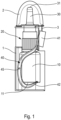
- la
figure 1 représente une vue schématique de côté d'un ensemble selon un premier mode de réalisation avantageux, avant retrait du capot de protection ; - [les
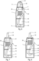
figures 2 et 3 représentent des vues schématiques de côté de l'ensemble de lafigure 1 , respectivement en position de repos et en position actionnée ; - les
figures 4 et 5 représentent des vues schématiques partielles en perspective selon deux angles de vue différents d'un élément d'actionnement latéral selon une variante avantageuse associé à un distributeur de produit fluide; - la
figure 6 représente une vue schématique de côté d'un ensemble selon un second mode de réalisation avantageux, avant retrait du capot de protection ; et - les
figures 7 et 8 représentent des vues schématiques de côté de l'ensemble de lafigure 6 , respectivement en position de repos et en position actionnée.
- there
figure 1 shows a schematic side view of an assembly according to a first advantageous embodiment, before removal of the protective cover; - [THE
figures 2 and 3 represent schematic side views of the entirefigure 1 , respectively in the rest position and in the actuated position; - THE
figures 4 and 5 represent partial schematic perspective views from two different angles of view of a lateral actuation element according to an advantageous variant associated with a fluid dispenser; - there
figure 6 shows a schematic side view of an assembly according to a second advantageous embodiment, before removal of the protective cover; And - THE
figures 7 and 8 represent schematic side views of the entirefigure 6 , respectively in the rest position and in the actuated position.
Dans la description ci-après, les termes "supérieur", "inférieur", "haut" et "bas" se réfèrent à la position droite du dispositif représentée sur les figures. Les termes "axial", "latéral" et "radial" se réfèrent à l'axe central longitudinal du distributeur.In the description below, the terms "upper", "lower", "top" and "bottom" refer to the upright position of the device shown in the figures. The terms "axial", "lateral" and "radial" refer to the central longitudinal axis of the distributor.
En se référant aux figures, qui illustrent deux modes de réalisation avantageux, il est représenté un ensemble de distribution comportant d'une part un dispositif d'actionnement latéral et d'autre part un distributeur de produit fluide, notamment un dispositif de pulvérisation nasale.Referring to the figures, which illustrate two advantageous embodiments, there is shown a dispensing assembly comprising on the one hand a lateral actuation device and on the other hand a fluid dispenser, in particular a nasal spray device.
Le distributeur de produit fluide comporte un réservoir 10 qui contient du produit fluide, notamment du produit pharmaceutique destiné à être pulvérisé dans le nez d'un utilisateur. Un organe de distribution 20, tel qu'une pompe ou une valve, est assemblé sur ledit réservoir 10, au moyen d'une bague de fixation (non représentée) qui peut être sertissable, encliquetable ou vissable. L'organe de distribution 20, qui n'est pas représenté en détail sur les figures, comporte classiquement un corps d'organe de distribution, tel qu'un corps de pompe ou un corps de valve, et un organe mobile, tel qu'une tige de piston ou une soupape de valve, qui est monté coulissant axialement dans ledit corps d'organe de distribution. De manière classique, l'organe mobile est enfoncé à l'intérieur du corps d'organe de distribution, pour actionner ledit organe de distribution. Une tête de distribution 30 est assemblée sur ledit organe de distribution 20, ladite tête de distribution 30 incorporant un orifice de distribution 31 à travers lequel le produit fluide est distribué.The fluid dispenser comprises a
Un dispositif d'actionnement latéral est prévu pour être utilisable avec plusieurs distributeurs de produit fluide. Ainsi, le distributeur de produit fluide est monté de manière amovible dans ledit dispositif d'actionnement latéral, et lorsque le réservoir 10 est vide, le distributeur est retiré et remplacé par un autre distributeur comportant un réservoir 10 plein.A lateral actuation device is provided to be usable with several fluid dispensers. Thus, the fluid dispenser is removably mounted in said lateral actuation device, and when the
Le dispositif d'actionnement latéral comporte un corps 1 adapté à recevoir ledit distributeur. Le corps 1 peut être réalisé en une seule partie monobloc, ou il peut comporter deux ou plusieurs parties fixées l'une à l'autre lors de l'assemblage du distributeur dans le corps. Dans la suite de la description, il sera fait référence au corps 1, étant entendu que ceci englobe les deux variantes ci-dessus.The lateral actuation device comprises a
Avantageusement, le corps 1 est ouvert axialement vers le haut pour permettre l'insertion et le retrait du distributeur à travers cette ouverture axiale. Avec un corps 1 en plusieurs parties assemblées, on pourrait envisager un sens d'assemblage différent.Advantageously, the
Un capot de protection amovible 2 est assemblé sur le corps 1 pour protéger l'orifice de distribution 31 entre deux actionnements. Ce capot 2 peut comporter une extension 3 qui bloque l'actionnement du dispositif d'actionnement latéral lorsque le capot 2 est en place sur le corps 1. Ceci permet d'empêcher tout actionnement accidentel, par exemple pendant le transport.A removable
Le dispositif d'actionnement latéral comporte un élément d'actionnement latéral 40 solidaire du corps 1 et adapté à coopérer avec le réservoir 10. Cet élément d'actionnement latéral 40 comporte une partie d'appui 41 sur laquelle l'utilisateur appuie pour actionner le distributeur, et une partie de poussée 42 coopérant avec le fond 11 du réservoir 10. L'élément d'actionnement latéral 40 est monté pivotant sur le corps 1 autour d'un axe 45.The lateral actuating device comprises a lateral actuating
Selon l'invention, l'élément d'actionnement latéral 40 a environ une forme de S ou de S inversé, cette seconde variante étant celle représentée sur les dessins. Ainsi, la partie d'appui 41 est disposée à proximité de la tête de distribution 30 et la partie de poussée 42 est disposée sous le fond 11 du réservoir 10. L'axe de pivotement 45 est disposé entre ladite partie d'appui 41 et ladite partie de poussée 42. Cette forme en S ou S inversé de l'élément d'actionnement 40 permet de limiter son encombrement latéral, de sorte qu'en position de repos, visible sur les
Comme visible sur les
De préférence, l'élément d'actionnement 40 comporte deux branches identiques parallèles 46, 47 reliées l'une à l'autre par les partie d'appui 41 et de poussée 42, comme visible notamment sur les
Dans le mode de réalisation des
En fonctionnement, l'utilisateur appuie sur la partie d'appui 41 de l'élément d'actionnement 40 pour le faire pivoter par rapport au corps 1 autour de l'axe 45. Ce pivotement de l'élément d'actionnement 40 provoque le déplacement axial vers le haut de la partie de poussée 42 et donc du réservoir 10 et ainsi l'actionnement de l'organe de distribution 20.In operation, the user presses on the
L'élément d'actionnement 40 peut comporter un élément élastique (non représenté), tel qu'une lame élastique ou un ressort, qui sollicite élastiquement ledit élément d'actionnement 40 vers sa position de repos. En variante, l'élément d'actionnement 40 peut être ramené vers sa position de repos par le réservoir 10 lorsqu'il revient vers sa position de repos après chaque actionnement sous l'effet du ressort de rappel de l'organe de distribution 20.Actuating
Bien que l'invention ait été décrite en références à des modes de réalisations regroupant plusieurs des aspects décrits ci-dessus, il est entendu que diverses modifications sont envisageables pour l'homme du métier sans sortir du cadre de la présente invention tel que défini par les revendications annexées.Although the invention has been described with reference to embodiments combining several of the aspects described above, it is understood that various modifications are possible for those skilled in the art without departing from the scope of the present invention as defined by the appended claims.
Claims (7)
- Dispensing assembly, comprising a fluid product dispenser, such as a nasal dispensing device, wherein said fluid product dispenser comprises a reservoir (10) provided with a bottom (11), a dispensing member (20), such as a pump or a valve, mounted on said reservoir (10) and a dispensing head (30) incorporating a dispensing orifice (31), said dispensing assembly comprising a lateral actuation device comprising a body (1) and a lateral actuation element (40) mounted on said body (1) to pivot about a pivot axis (45) between a rest position and an actuation position, said actuation element (40) comprising a bearing part (41), on which the user presses during actuation, and a pushing part (42) adapted to cooperate with said fluid product dispenser to effect actuation thereof, said pivot axis (45) being arranged between said bearing part (41) and said pushing part (42), said lateral actuation element (40) having a shape of S or inverted S, said bearing part (41) being arranged close to said dispensing head (30) and said pushing part (42) being arranged under said bottom (11) of said reservoir (10), said actuation element (40) comprising two parallel identical branches (46, 47) connected to one another by said bearing (41) and pushing (42) parts, characterized in that said branches (46, 47) comprise a first curvature at their joining to said bearing part (41) and a second curvature, opposite said first curvature, at their joining to said pushing part (42).
- Assembly according to claim 1, wherein said first and second curvatures are facing towards the inside of said body (1).
- Assembly according to claim 1 or 2, wherein said pivot axis (45) is arranged closer to said pushing part (42) than said bearing part (41).
- Assembly according to any one of the preceding claims, wherein a removable protective cap (2) is mounted on said body (1).
- Assembly according to claim 4, wherein said protective cap (2) comprises an axial extension (3) cooperating with said actuation element (40) to prevent its pivoting.
- Assembly according to any one of the preceding claims, wherein said pivot axis (45) extends radially outside said reservoir (10).
- Assembly according to any one of claims 1 to 5, wherein said pivot axis (45) is arranged substantially secant to the longitudinal central axis of said reservoir (10).
Applications Claiming Priority (2)
| Application Number | Priority Date | Filing Date | Title |
|---|---|---|---|
| FR1908524A FR3099070B1 (en) | 2019-07-26 | 2019-07-26 | Lateral actuation device for fluid dispenser |
| PCT/FR2020/051301 WO2021019145A1 (en) | 2019-07-26 | 2020-07-20 | Dispensing assembly comprising a lateral actuation device for a fluid product dispenser |
Publications (2)
| Publication Number | Publication Date |
|---|---|
| EP4003607A1 EP4003607A1 (en) | 2022-06-01 |
| EP4003607B1 true EP4003607B1 (en) | 2023-09-06 |
Family
ID=68806987
Family Applications (1)
| Application Number | Title | Priority Date | Filing Date |
|---|---|---|---|
| EP20757378.3A Active EP4003607B1 (en) | 2019-07-26 | 2020-07-20 | Dispensing assembly with a lateral actuating device for a fluid product dispenser |
Country Status (5)
| Country | Link |
|---|---|
| US (1) | US20220362488A1 (en) |
| EP (1) | EP4003607B1 (en) |
| CN (1) | CN114222599A (en) |
| FR (1) | FR3099070B1 (en) |
| WO (1) | WO2021019145A1 (en) |
Family Cites Families (10)
| Publication number | Priority date | Publication date | Assignee | Title |
|---|---|---|---|---|
| US3084871A (en) * | 1961-07-24 | 1963-04-09 | Synfleur Scient Lab Inc | Selective spray dispenser |
| US3478935A (en) * | 1968-02-16 | 1969-11-18 | Texize Chem Inc | Dispensing device |
| GB1531308A (en) * | 1976-11-22 | 1978-11-08 | Johnson & Son Inc S C | Dispensing receptacle for aerosol container |
| FR2812826B1 (en) * | 2000-08-11 | 2003-04-18 | Valois Sa | SIDE OPERATION SPRAYING DEVICE, ESPECIALLY NASAL PUSH-BUTTON |
| AUPS286302A0 (en) * | 2002-06-07 | 2002-06-27 | Kabila Investments Pty. Limited | Medication inhaler |
| ITRM20050559A1 (en) * | 2005-11-10 | 2007-05-11 | Emsar Spa | NEBULIZER MICROPUMP EQUIPPED WITH A ROLLER COVERING AND TRIGGER ELEMENT OF ITS DISPENSER KEY. |
| US7699191B2 (en) * | 2006-11-09 | 2010-04-20 | Ethicon Endo-Surgery, Inc. | Surgical multiple use adhesive applier |
| EP1974829B1 (en) * | 2007-03-26 | 2010-07-28 | Ing. Erich Pfeiffer GmbH | Dispensing device for fluids |
| FR2932399B1 (en) * | 2008-06-17 | 2011-10-28 | Valois Sas | DEVICE FOR DISPENSING FLUID PRODUCT |
| US20150352574A1 (en) * | 2012-11-19 | 2015-12-10 | Colgate-Palmolive Company | Multi-chamber container |
-
2019
- 2019-07-26 FR FR1908524A patent/FR3099070B1/en active Active
-
2020
- 2020-07-20 US US17/630,366 patent/US20220362488A1/en active Pending
- 2020-07-20 WO PCT/FR2020/051301 patent/WO2021019145A1/en active Search and Examination
- 2020-07-20 CN CN202080053894.4A patent/CN114222599A/en active Pending
- 2020-07-20 EP EP20757378.3A patent/EP4003607B1/en active Active
Also Published As
| Publication number | Publication date |
|---|---|
| US20220362488A1 (en) | 2022-11-17 |
| WO2021019145A1 (en) | 2021-02-04 |
| CN114222599A (en) | 2022-03-22 |
| EP4003607A1 (en) | 2022-06-01 |
| FR3099070A1 (en) | 2021-01-29 |
| FR3099070B1 (en) | 2021-11-12 |
Similar Documents
| Publication | Publication Date | Title |
|---|---|---|
| EP1855961B1 (en) | Fluid product dispensing head | |
| EP1315576B1 (en) | Multiple-dose device for dispensing a fluid product | |
| EP2136931B1 (en) | Device for dispensing a liquid to pasty product with a dosing pump | |
| EP2310141B1 (en) | Fluid product dispensing device | |
| EP1029808B1 (en) | Lockable dispensing head and dispenser with such head | |
| EP1183194A2 (en) | Product dispensing device comprising a reservoir housed in a casing | |
| EP3107821B1 (en) | Device for packaging and dispensing a product having a dosing nozzle | |
| EP1497036B1 (en) | Distribution device for a fluid product | |
| EP2310140B1 (en) | Dispensing device for a fluid product | |
| WO2003043909A2 (en) | Lateral actuation spray device | |
| EP1661822B1 (en) | Container and dispenser for a product | |
| EP4003607B1 (en) | Dispensing assembly with a lateral actuating device for a fluid product dispenser | |
| FR2871712A1 (en) | Container and casing assembly for dispensing a cosmetic, hygiene or pharmaceutical product comprises a casing open at both ends and fitted with pusher base and head | |
| WO2013118074A1 (en) | Lateral actuator for a dispenser of a cosmetics container | |
| WO2009147350A2 (en) | Device for dispensing a fluid product | |
| FR2692559A1 (en) | Security system for dispensing container - includes locking piece movable between locking position of operating tube and actuating position permitting dispensing of product | |
| FR2859464A1 (en) | Fluid, liquid or pastry product e.g. drug, distribution device, has force transmission part with hinge films spaced from each other in cylindrical body movement direction, and pivoting arms inclined relative to support unit for being folded | |
| FR2750113A1 (en) | DISTRIBUTION DEVICE WITH OPERATION SECURITY AND RECHARGE OF SUCH A DEVICE | |
| FR2856993A1 (en) | Fluid product distributing device, has distributing nozzle connected in inseparable manner to pump by flexible connecting unit when pump moves between resting and distributing positions |
Legal Events
| Date | Code | Title | Description |
|---|---|---|---|
| STAA | Information on the status of an ep patent application or granted ep patent |
Free format text: STATUS: UNKNOWN |
|
| STAA | Information on the status of an ep patent application or granted ep patent |
Free format text: STATUS: THE INTERNATIONAL PUBLICATION HAS BEEN MADE |
|
| PUAI | Public reference made under article 153(3) epc to a published international application that has entered the european phase |
Free format text: ORIGINAL CODE: 0009012 |
|
| STAA | Information on the status of an ep patent application or granted ep patent |
Free format text: STATUS: REQUEST FOR EXAMINATION WAS MADE |
|
| 17P | Request for examination filed |
Effective date: 20220222 |
|
| AK | Designated contracting states |
Kind code of ref document: A1 Designated state(s): AL AT BE BG CH CY CZ DE DK EE ES FI FR GB GR HR HU IE IS IT LI LT LU LV MC MK MT NL NO PL PT RO RS SE SI SK SM TR |
|
| DAV | Request for validation of the european patent (deleted) | ||
| DAX | Request for extension of the european patent (deleted) | ||
| REG | Reference to a national code |
Ref legal event code: R079 Ref document number: 602020017326 Country of ref document: DE Free format text: PREVIOUS MAIN CLASS: B05B0011000000 Ref country code: DE Ipc: B05B0011100000 |
|
| GRAP | Despatch of communication of intention to grant a patent |
Free format text: ORIGINAL CODE: EPIDOSNIGR1 |
|
| STAA | Information on the status of an ep patent application or granted ep patent |
Free format text: STATUS: GRANT OF PATENT IS INTENDED |
|
| RIC1 | Information provided on ipc code assigned before grant |
Ipc: A61M 15/08 20060101ALI20230207BHEP Ipc: A61M 15/00 20060101ALI20230207BHEP Ipc: B05B 11/00 20060101ALI20230207BHEP Ipc: B05B 11/10 20230101AFI20230207BHEP |
|
| INTG | Intention to grant announced |
Effective date: 20230227 |
|
| GRAS | Grant fee paid |
Free format text: ORIGINAL CODE: EPIDOSNIGR3 |
|
| RIN1 | Information on inventor provided before grant (corrected) |
Inventor name: GRAINE, LILA Inventor name: ADAM, FABIEN |
|
| GRAA | (expected) grant |
Free format text: ORIGINAL CODE: 0009210 |
|
| STAA | Information on the status of an ep patent application or granted ep patent |
Free format text: STATUS: THE PATENT HAS BEEN GRANTED |
|
| AK | Designated contracting states |
Kind code of ref document: B1 Designated state(s): AL AT BE BG CH CY CZ DE DK EE ES FI FR GB GR HR HU IE IS IT LI LT LU LV MC MK MT NL NO PL PT RO RS SE SI SK SM TR |
|
| REG | Reference to a national code |
Ref country code: GB Ref legal event code: FG4D Free format text: NOT ENGLISH |
|
| REG | Reference to a national code |
Ref country code: CH Ref legal event code: EP |
|
| REG | Reference to a national code |
Ref country code: IE Ref legal event code: FG4D Free format text: LANGUAGE OF EP DOCUMENT: FRENCH |
|
| REG | Reference to a national code |
Ref country code: DE Ref legal event code: R096 Ref document number: 602020017326 Country of ref document: DE |
|
| P01 | Opt-out of the competence of the unified patent court (upc) registered |
Effective date: 20230913 |
|
| REG | Reference to a national code |
Ref country code: LT Ref legal event code: MG9D |
|
| REG | Reference to a national code |
Ref country code: NL Ref legal event code: MP Effective date: 20230906 |
|
| PG25 | Lapsed in a contracting state [announced via postgrant information from national office to epo] |
Ref country code: GR Free format text: LAPSE BECAUSE OF FAILURE TO SUBMIT A TRANSLATION OF THE DESCRIPTION OR TO PAY THE FEE WITHIN THE PRESCRIBED TIME-LIMIT Effective date: 20231207 |
|
| PG25 | Lapsed in a contracting state [announced via postgrant information from national office to epo] |
Ref country code: SE Free format text: LAPSE BECAUSE OF FAILURE TO SUBMIT A TRANSLATION OF THE DESCRIPTION OR TO PAY THE FEE WITHIN THE PRESCRIBED TIME-LIMIT Effective date: 20230906 Ref country code: RS Free format text: LAPSE BECAUSE OF FAILURE TO SUBMIT A TRANSLATION OF THE DESCRIPTION OR TO PAY THE FEE WITHIN THE PRESCRIBED TIME-LIMIT Effective date: 20230906 Ref country code: NO Free format text: LAPSE BECAUSE OF FAILURE TO SUBMIT A TRANSLATION OF THE DESCRIPTION OR TO PAY THE FEE WITHIN THE PRESCRIBED TIME-LIMIT Effective date: 20231206 Ref country code: LV Free format text: LAPSE BECAUSE OF FAILURE TO SUBMIT A TRANSLATION OF THE DESCRIPTION OR TO PAY THE FEE WITHIN THE PRESCRIBED TIME-LIMIT Effective date: 20230906 Ref country code: LT Free format text: LAPSE BECAUSE OF FAILURE TO SUBMIT A TRANSLATION OF THE DESCRIPTION OR TO PAY THE FEE WITHIN THE PRESCRIBED TIME-LIMIT Effective date: 20230906 Ref country code: HR Free format text: LAPSE BECAUSE OF FAILURE TO SUBMIT A TRANSLATION OF THE DESCRIPTION OR TO PAY THE FEE WITHIN THE PRESCRIBED TIME-LIMIT Effective date: 20230906 Ref country code: GR Free format text: LAPSE BECAUSE OF FAILURE TO SUBMIT A TRANSLATION OF THE DESCRIPTION OR TO PAY THE FEE WITHIN THE PRESCRIBED TIME-LIMIT Effective date: 20231207 Ref country code: FI Free format text: LAPSE BECAUSE OF FAILURE TO SUBMIT A TRANSLATION OF THE DESCRIPTION OR TO PAY THE FEE WITHIN THE PRESCRIBED TIME-LIMIT Effective date: 20230906 |
|
| REG | Reference to a national code |
Ref country code: AT Ref legal event code: MK05 Ref document number: 1607791 Country of ref document: AT Kind code of ref document: T Effective date: 20230906 |
|
| PG25 | Lapsed in a contracting state [announced via postgrant information from national office to epo] |
Ref country code: NL Free format text: LAPSE BECAUSE OF FAILURE TO SUBMIT A TRANSLATION OF THE DESCRIPTION OR TO PAY THE FEE WITHIN THE PRESCRIBED TIME-LIMIT Effective date: 20230906 |
|
| PG25 | Lapsed in a contracting state [announced via postgrant information from national office to epo] |
Ref country code: IS Free format text: LAPSE BECAUSE OF FAILURE TO SUBMIT A TRANSLATION OF THE DESCRIPTION OR TO PAY THE FEE WITHIN THE PRESCRIBED TIME-LIMIT Effective date: 20240106 |