EP4003434B1 - Positionierungs- und stützvorrichtung für endoskopische, zu waschende instrumente - Google Patents
Positionierungs- und stützvorrichtung für endoskopische, zu waschende instrumente Download PDFInfo
- Publication number
- EP4003434B1 EP4003434B1 EP20761330.8A EP20761330A EP4003434B1 EP 4003434 B1 EP4003434 B1 EP 4003434B1 EP 20761330 A EP20761330 A EP 20761330A EP 4003434 B1 EP4003434 B1 EP 4003434B1
- Authority
- EP
- European Patent Office
- Prior art keywords
- positioning
- support device
- tubular element
- treatment
- fluid
- Prior art date
- Legal status (The legal status is an assumption and is not a legal conclusion. Google has not performed a legal analysis and makes no representation as to the accuracy of the status listed.)
- Active
Links
Images

Classifications
-
- A—HUMAN NECESSITIES
- A61—MEDICAL OR VETERINARY SCIENCE; HYGIENE
- A61L—METHODS OR APPARATUS FOR STERILISING MATERIALS OR OBJECTS IN GENERAL; DISINFECTION, STERILISATION OR DEODORISATION OF AIR; CHEMICAL ASPECTS OF BANDAGES, DRESSINGS, ABSORBENT PADS OR SURGICAL ARTICLES; MATERIALS FOR BANDAGES, DRESSINGS, ABSORBENT PADS OR SURGICAL ARTICLES
- A61L2/00—Disinfection or sterilisation of materials or objects, in general; Accessories therefor
- A61L2/16—Disinfection or sterilisation of materials or objects, in general; Accessories therefor using chemical substances
- A61L2/18—Liquid substances
-
- A—HUMAN NECESSITIES
- A61—MEDICAL OR VETERINARY SCIENCE; HYGIENE
- A61B—DIAGNOSIS; SURGERY; IDENTIFICATION
- A61B90/00—Instruments, implements or accessories specially adapted for surgery or diagnosis and not covered by any of the groups A61B1/00 - A61B50/00, e.g. for luxation treatment or for protecting wound edges
- A61B90/70—Cleaning devices specially adapted for surgical instruments
-
- A—HUMAN NECESSITIES
- A61—MEDICAL OR VETERINARY SCIENCE; HYGIENE
- A61L—METHODS OR APPARATUS FOR STERILISING MATERIALS OR OBJECTS IN GENERAL; DISINFECTION, STERILISATION OR DEODORISATION OF AIR; CHEMICAL ASPECTS OF BANDAGES, DRESSINGS, ABSORBENT PADS OR SURGICAL ARTICLES; MATERIALS FOR BANDAGES, DRESSINGS, ABSORBENT PADS OR SURGICAL ARTICLES
- A61L2/00—Disinfection or sterilisation of materials or objects, in general; Accessories therefor
- A61L2/26—Accessories
-
- B—PERFORMING OPERATIONS; TRANSPORTING
- B08—CLEANING
- B08B—CLEANING IN GENERAL; PREVENTION OF FOULING IN GENERAL
- B08B3/00—Cleaning by methods involving the use or presence of liquid or steam
- B08B3/04—Cleaning involving contact with liquid
- B08B3/06—Cleaning involving contact with liquid using perforated drums in which the article or material is placed
-
- A—HUMAN NECESSITIES
- A61—MEDICAL OR VETERINARY SCIENCE; HYGIENE
- A61B—DIAGNOSIS; SURGERY; IDENTIFICATION
- A61B90/00—Instruments, implements or accessories specially adapted for surgery or diagnosis and not covered by any of the groups A61B1/00 - A61B50/00, e.g. for luxation treatment or for protecting wound edges
- A61B90/70—Cleaning devices specially adapted for surgical instruments
- A61B2090/701—Cleaning devices specially adapted for surgical instruments for flexible tubular instruments, e.g. endoscopes
-
- A—HUMAN NECESSITIES
- A61—MEDICAL OR VETERINARY SCIENCE; HYGIENE
- A61L—METHODS OR APPARATUS FOR STERILISING MATERIALS OR OBJECTS IN GENERAL; DISINFECTION, STERILISATION OR DEODORISATION OF AIR; CHEMICAL ASPECTS OF BANDAGES, DRESSINGS, ABSORBENT PADS OR SURGICAL ARTICLES; MATERIALS FOR BANDAGES, DRESSINGS, ABSORBENT PADS OR SURGICAL ARTICLES
- A61L2103/00—Materials or objects being the target of disinfection or sterilisation
- A61L2103/15—Laboratory, medical or dentistry appliances, e.g. catheters or sharps
Definitions
- Embodiments described here concern a positioning and support device that can be used to perform targeted washing treatments on a distal end of endoscopic instruments, that is, the terminal part of the endoscopic instrument that is normally introduced inside a human body.
- Said positioning and support device can be used in itself, or be used in cooperation with a washing rack or tray, and possibly integrated as part of a rack or tray.
- Embodiments described here also concern a method for treating an endoscopic instrument, for example washing, disinfection or sterilization.
- endoscopes are commonly used for both diagnostic and also for therapeutic purposes.
- endoscopes can be used to diagnose and/or treat medical pathologies involving the lungs, esophagus, stomach, small intestine, biliary tract, pancreas or colon.
- endoscopes are instruments that are reused numerous times on different patients and therefore a high-level disinfection is necessary in order to eliminate any bacterial loads that could contaminate a subsequent patient.
- infections can occur which can be the result of the flora of the previous patient, or the result of microbes introduced through the endoscope.
- Endoscopes generally consist of one or more materials that can be chemically sensitive or that can degrade over time and with use.
- Endoscopes are therefore subjected to disinfection, meaning by this term the removal or elimination of most, but not all, microorganisms.
- Duodenoscopes in fact, have a specific structure in correspondence with their distal end, which can be used to modify the angle of the catheters, called the elevator, or fin, and a channel associated with it.
- the elevator can be rotated between a lowered position, in which it is substantially aligned with a longitudinal axis of the endoscope, to allow it to slide inside the human body, and a raised position, in which it is rotated with respect to said axis and protrudes in the transverse direction to be able to exert an opening action on a part of the duodenum.
- MDRO multi-drug resistant organisms
- CRE Carbapenem-resistant enterobacteria
- CRE are only the infectious agents that have recently been associated with endoscopes that have turned out to be contaminated, but many other pathologies that can be transmitted through endoscopic procedures are also known.
- the guidelines require manual pre-washing, using brushes, or pipe cleaners, of the distal end, and subsequent washing using suitable treatment machines.
- treatment machines which provide to treat the endoscopic instrument by immersion.
- immersion treatment machines require the use of large quantities of treatment liquid and in any case do not guarantee an optimal level of disinfection in the case of treating the distal end of a duodenoscope.
- Apparatuses for washing endoscopes are also known, provided with support devices, and in which the articles to be washed and disinfected are positioned and clamped in an adequate manner. The articles are then hit by jets of washing liquid in suitable treatment machines.
- these known solutions do not guarantee specific cleaning of the distal end of the duodenoscopes, since the protruding elevator tends to form shadow zones which hinder the jets and the splashes of treatment fluid and in fact invalidate the effectiveness of the cleaning treatment.
- Document EP-A-1 949 868 describes a washing device for a medical instrument of the tubular type, comprising a first external tubular element, means to deliver a washing liquid in the first tubular element, and a second tubular element disposed inside the first tubular element, defining with it an interspace and provided with a plurality of slits through which the washing liquid can pass.
- the entry of the washing liquid and the discharge outlet are located in opposite positions to each other in relation to the longitudinal extension of the device, and the water is introduced into the interspace in a radial direction.
- Document WO-A-96/41686 describes a device for treating and disinfecting medical instruments comprising a treatment chamber having an external wall and an internal wall, the latter provided with a plurality of holes, separated by an interspace divided in an axial direction into truncated cone spaces.
- the interspace is connected to a sleeve provided with a plurality of valves to introduce a mixture of air and water in a radial direction into each sector; the mixture, through the holes, reaches the instrument to be washed and is finally sucked up and discharged through an exit aperture by the Venturi effect.
- This solution which requires to deliver jets of fluid for each sector, entails a complex construction, and electronic elements such as electro valves, and therefore it is not suitable to be inserted inside a treatment and washing machine.
- one purpose of the present invention is to provide a positioning and support device which allows great simplicity of use.
- Another purpose of the present invention is to provide a positioning and support device for washing the distal end of an endoscope which can be used both for itself and in any treatment machine.
- Another purpose of the present invention is to provide a positioning and support device which allows to increase the efficiency of the washing treatment of the distal end of endoscopes, and in particular of duodenoscopes.
- Another purpose is to provide a positioning and support device which is also simple to clean and sterilize.
- One purpose of the present invention is also to provide a positioning and support device which facilitates the discharge of the washing fluid, preventing any accumulation thereof inside it.
- Another purpose of the invention is to provide a positioning and support device that can be easily adapted to different configurations of use, alone or in combination with known racks or trays for treating endoscopic instruments.
- Another purpose of the present invention is to perfect a method for treating endoscopes, in particular duodenoscopes, which allows to perform an accurate treatment of the distal end thereof.
- the Applicant has devised, tested and embodied the present invention to overcome the shortcomings of the state of the art and to obtain these and other purposes and advantages.
- the invention concerns a positioning and support device provided with a containing chamber suitable to contain at least the distal end of an endoscopic instrument, for example the terminal part provided with an elevator to be subjected to washing treatment, and possible sterilization and/or disinfection.
- the positioning and support device can be used on its own or in association with machines that carry out the treatment of endoscopic instruments, for example cooperating with baskets or trays of known treatment and washing machines.
- the positioning and support device according to the invention while being advantageously suitable to house and subject to treatment the distal end of an endoscopic instrument, can also be used to support a terminal part of other articles, possibly of different shapes and types, for which it is necessary to carry out a targeted treatment.
- the positioning and support device comprises:
- the positioning and support device comprises a fluidic circuit defined by the association of the two tubular elements, which has an entry in correspondence with the entry for the fluid, and an exit in correspondence with the second discharge aperture.
- a pressurized fluid can be introduced into the circuit by means of introduction means through the entry of the fluid, reaching and distributing itself in the hollow space from which, passing through the holes located on the body of the internal tubular element, it flows in the form of jets inside the chamber. Once in the chamber, the fluid, together with the possible dirt removed from the endoscope, flows outside through the exit aperture.
- the treatment fluid is introduced into the hollow space in an axial direction, promoting its distribution in a circumferential direction.
- the entry for the fluid and the discharge exit are made on a same side of the positioning and support device. Combined with the fact that the hollow space is at least partly closed on the opposite side, this allows on the one hand to guarantee that the fluid is distributed and is delivered with uniform pressure through all the through holes toward the device to be washed, and on the other to guarantee that no treatment fluid accumulates in the hollow space itself.
- the positioning and support device comprises a compartment to distribute the fluid that has an annular shape, delimited on one side by an external wall in which the entry is made and, on the opposite side, by an internal wall comprising at least three through slits communicating with the hollow space.
- the distribution compartment downstream of the hollow space allows to obtain a uniform distribution of the flow in the latter, and therefore a better delivery of the washing liquid toward the instrument to be washed.
- said external tubular element is provided with a separating wall, or partition, defining said internal wall and comprising said exit made in a central portion thereof and said through slits disposed equally distanced around said exit.
- the through holes can be disposed substantially along the circumferential and longitudinal development of the treatment chamber.
- the through holes are configured to generate a plurality of jets so as to act on the terminal end substantially at 360°.
- the holes can be simple single-diameter holes, or they can be countersunk holes, for example having a smaller diameter toward the chamber so as to reduce the section for the exit of the treatment fluid and increase its pressure.
- the holes can have a helical development so as to generate rotating jets which act aggressively on said terminal part.
- the holes can be evenly distributed on the periphery of the chamber, or they can be distributed differently according to the complexity of the zone on which the jets operate.
- the holes can be arranged aligned on parallel lines.
- the holes can be arranged according to a helix-shaped curve.
- the holes have different sizes and/or orientation according to the position in which they are located inside the chamber.
- the internal tubular element comprises an annular portion, protruding from an external surface, which haa a radial extension correlated to the width of the hollow space, and configured to act as closure of the latter's end when the internal cylinder is inserted in, and assembled to, the external cylinder.
- the internal tubular element and the external tubular element are provided with respective and mating coupling members and joining members, suitable to guarantee a stable reciprocal coupling of the two elements.
- the positioning and support device comprises a support base configured to support the external tubular element assembled to the internal tubular element so that the discharge aperture is positioned at a lower height with respect to the entry aperture.
- Some embodiments described here also concern a method to carry out a washing, sterilization and/or disinfection treatment of an endoscopic instrument in a positioning and support device according to the invention.
- the method provides to position the distal end of an oblong body in the treatment chamber, introduce a pressurized fluid into the hollow space so as to generate a plurality of sprays and jets of treatment fluid inside the treatment chamber directed toward different positions of the distal end, and discharge the treatment fluid together with possible residual dirt through the exit aperture.
- the type and/or pressure of the treatment fluid are correlated to the type and/or conditions of the terminal part to be subjected to washing.
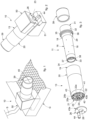
- Embodiments described here concern a positioning and support device indicated as a whole with reference number 10 suitable to contain at least one distal end E of an oblong body, that is, having a prevalent size along a longitudinal development, for example the terminal part of an endoscopic instrument to be subjected to washing treatment, and possible sterilization and/or disinfection.
- the positioning and support device 10 can be used on its own or in association with machines that carry out the treatment of endoscopic instruments.
- the positioning and support device 10 comprises a first internal tubular element 11, which is internally hollow and defines a treatment chamber 12 configured to house and contain the distal end E of the article to be subjected to treatment, such as for example the terminal part of an endoscopic instrument.
- the positioning and support device 10 also comprises an external tubular element 13, coaxially associated with the internal tubular element 11 so as to define a hollow space 14 with it.
- the hollow space 14 can have an annular shape, with a substantially constant width along its longitudinal development, and is configured to act as a distribution chamber for a treatment fluid before its introduction into the chamber 12.
- the internal tubular element 11 has a body 16 on which a plurality of through holes 18 open, configured to put the hollow space 14 in fluidic communication with the treatment chamber 12.
- the hollow space 14 is at least partially closed at one end and has, at the opposite end, an entry 15 for the treatment fluid suitable to be connected, during use, to means to feed the treatment fluid.
- the hollow space 14 on the end opposite the entry 15 can be completely closed or partly closed, since one or more holes 18 for the passage of the treatment fluid can be provided.
- the entry 15 for the fluid is configured to introduce the treatment fluid inside the hollow space 14 along an axial direction, that is, in a direction substantially parallel to a longitudinal axis of the positioning and support device 10.
- the positioning and support device 10 also includes an exit 23 communicating with the treatment chamber 12 and configured to allow the discharge and the outflow of the dirty fluid out of the chamber 12 ( figs. 3 and 4 ).
- the entry 15 for the fluid and the discharge exit 23 are made on a same side of the positioning and support device 10. In this way, possible residues of treatment fluid can also be advantageously discharged through the entry 15 without accumulating inside the hollow space 14.
- the external tubular element 13 has, in correspondence with a first end defining a neck portion 20, a first aperture 19, configured to allow the insertion therein of the internal tubular body 11.
- the external tubular element 13 also comprises, in correspondence with a second end, opposite the first, and defining a bottom portion 21, the discharge exit 23.
- the external tubular element 13 can have a tapered external profile so that the aperture 19 has a slightly larger diameter than the bottom 21.
- the aperture 19 can be sized to receive a suitable internal tubular element 11.
- the elements 11, 13 can be made of polymeric plastic material, preferably polypropylene modified with the addition of glass fiber.
- the elements 11, 13 can be made of the same material.
- polypropylene modified with the addition of glass fiber is particularly advantageous to withstand the conditions required in the washing and/or sterilization step. For example, it allows the device 10 to withstand high temperatures (over 100°C) and/or contact with acid or alkaline cleaning fluids and/or high pressures.
- the device 10 can be made of any other material whatsoever suited to the purposes of the invention.
- the positioning and support device 10 between the entry 15 and the hollow space 14 comprises a compartment 43 to distribute the fluid which has an annular shape.
- This distribution compartment is delimited on one side by an external wall 43a in which the entry 15 for the fluid is made and, on the opposite side, by an internal wall 43b comprising at least three through slits 24 communicating with the hollow space 14.
- the washing fluid that is introduced through the entry 15 can then distribute itself evenly in the hollow space 14.
- the bottom portion 21 can have a separating wall, or partition 22, in the central portion of which there is made the at least one exit 23 for the outflow of the dirty treatment fluid coming from the treatment chamber 12.
- the separating wall, or partition 22, defines the internal wall 43a of the distribution compartment 43.
- the sizes of the exit 23 can be chosen based on the volume of fluid that has to be drained from the chamber 12 so that dirty fluid does not stagnate in the chamber 12.
- the wall 22 is disposed in a recessed position with respect to an end edge of the external tubular body 13, that is, lying on a transverse plane that is more internal than that of the end of the bottom 21.
- the exit 23 can have an annular edge 41 which extends longitudinally toward the bottom 21, protruding with respect to the external surface of the wall 22.
- the plane of the annular edge 41 of the exit 23 can substantially coincide with an edge 42 of the end of the bottom 21.
- an abutment shoulder 25a that has a smaller extension than the edge 42 of the end of the bottom 21.
- the wall 22 also comprises through slits 24 communicating on one side with the entry for the fluid and configured to allow the passage of the treatment fluid through them toward the hollow space 14.
- At least three through slits 24 are provided, for example a number comprised between 3 and 15, as a function of their sizes and those of the external tubular element 13.
- the slits 24 are disposed and shaped to provide a homogeneous flow of the fluid within the hollow space 14.
- the slits 24 are disposed between the exit 23 and the abutment shoulder 25a.
- the slits 24 are disposed equally distanced around the exit 23.
- a second abutment shoulder 25b can be present between the slits 24 and the annular edge 41 of the exit 23.
- the second abutment shoulder 25b has a plane substantially coinciding with the plane of the abutment edge 25a.
- the compartment 43 configured to receive the treatment fluid from the entry 15 for the fluid and distribute it toward the slits 24.
- the positioning and support device 10 comprises a closing device 26, configured to cooperate with the external tubular element 13 to delimit the compartment 43 with it.
- the closing device 26 defines the external wall 43b of the compartment 43.
- the closing device 26 can be ring-shaped, and be configured to rest on and be associated with the abutment shoulders 25a, 25b, so as to close the compartment 43 and seal it hermetically.
- the closing device 26 comprises at least one aperture defining the entry for the fluid 15, communicating, during use, with the compartment 43 and the slits 24.
- the closing device 26 can be provided with a central hole 28 configured to cooperate with the annular edge 41 of the exit 23, so as to guarantee its correct positioning.
- the exiting dirty fluid is kept separate from the entering clean fluid.
- the closing device 26 can be made of a material different to that used for the tubular elements 11, 13, for example a metal alloy.
- the closing device 26 can be attached to the bottom 21 by means of attachment means which can be, for example, screws, rivets, glues, adhesives or other.
- the closing device 26 comprises a connector 44, fluidically communicating to the entry 15, and configured to be connected to feed means, or ducts S, suitable to deliver a fluid suitable to perform the tasks for which the device 10 is provided.
- the closing device 26 can be associated with the bottom 21 with attachment elements of the removable type so as to allow it to be replaced with one which, for example, provides a different connector 44 for association with different feed channels S.
- the closing device 26 can also be removed in order to perform cleaning operations, for example, of slits 24, possibly and at least partly blocked.
- the external tubular body 13 can comprise, in correspondence with the neck portion 20, coupling members 45 configured to cooperate with the internal tubular body 11 to allow a stable reciprocal coupling between the two elements.
- the internal tubular element 11 comprises, in correspondence with a first end defining a neck portion 32, a first entry aperture 31 configured to allow the insertion in and removal from the treatment chamber 12 of the terminal end E to be washed.
- the internal tubular element 11 also comprises, in correspondence with a second end, opposite the first, and defining a bottom portion 33, a separating wall or partition 37, provided with at least one through hole 38 through which the fluid of treatment can exit from chamber 12.
- the internal tubular element 11 can have a body 16 having a tapered profile between the neck portion 32 and the bottom portion 33, such that the smaller diameter is in correspondence with the bottom 33.
- the body 16 can have a variable thickness along its longitudinal and/or circumferential development.
- the neck portion 32 can have a larger diameter than the body 16.
- the through holes 18 can be made in the body 16 along its longitudinal extension between the neck portion 32 and the bottom portion 33.
- the neck portion 32 and the bottom portion 33 can be substantially free of through holes 18.
- the internal tubular element 11 can comprise a shoulder 29 which extends in a transverse direction with respect to the longitudinal axis and which has a larger diameter than that of the body 16.
- the shoulder 29 has a diameter substantially equal to the internal diameter of the external tubular element 13, so that, during use, it is suitable to be positioned in contact with the latter in such a way as to close the hollow space 14 in correspondence with the neck portion 20 of the latter.
- through holes 18 can be provided made in the thickness of the shoulder 29, suitable to allow the passage of the treatment fluid from the hollow space 14 toward the neck portion 32.
- a ring-shaped abutment portion 35 which protrudes beyond the shoulder 29, which is configured to position itself resting during use, on the upper edge of the first aperture 19 of the external tubular element 13 when the internal tubular element 11 is inserted into it.
- the internal tubular element 11 can have joining members 36 suitable to couple with the respective coupling members 45 of the external tubular element 13 so as to generate a substantially hermetic coupling.
- the coupling of the joining members 36 with the respective coupling members 45 can be either same shape, or snap-in, or by screwing or other suitable types.
- the joining members 36 can comprise a protruding tooth, while the coupling members 45 can comprise an attachment seating suitable to receive the tooth, thereby producing a same shape snap-in coupling with it.
- the partition 37 can be positioned on a more internal plane than the plane of the end of the bottom 33.
- a ring-shaped portion 34 that is full, that is, without holes, which, during use, positions itself resting against the internal surface of the separating wall 22 of the external tubular element 13.
- the body 16 defines the circular perimeter of the chamber 12 which develops substantially from the separating wall, or partition 37, up to, ideally, in correspondence with the shoulder 29.
- the sizes of the chamber 12 can be correlated at least to the type of distal end E of the endoscope to be subjected to treatment.
- the separating wall, or partition 37 can be advantageously provided to prevent the distal end E of the instrument to be cleaned from exiting from the chamber 12, nullifying the cleaning and/or possibly sterilization treatment.
- the separating wall, or partition 37 comprises a plurality of slits, or through holes 38, for example arranged along one or more circumferences.
- the slits 38 or holes can have a size sufficient to allow possible residues of dirt to exit from the chamber 12 preventing clogging.
- the hollow space 14 and the chamber 12 are in fluidic communication by means of holes 18 provided on the body 16.
- the holes 18 can be simple single-diameter holes, or countersunk closing advantageously toward the chamber 12 to generate a greater pressure.
- the holes 18 can have different sizes.
- the disposition of the holes 18 on the chamber 12 can be provided, for example in the shape of a helix, so as to generate rotating jets.
- the holes 18 can be equally distributed or be disposed with a higher density in correspondence with and/or according to the complexity of the zone on which the jets operate.
- the holes 18 can have a disposition pattern according to the conformation of the distal end E of the endoscope to be cleaned.
- indication elements can be provided, not shown, suitable to indicate the correct insertion orientation of the distal end E.
- the positioning and support device 10 also comprises a closing element 39, for example a lid or a cap, configured to at least partly close the entry aperture 31 to the chamber 12.
- a closing element 39 for example a lid or a cap, configured to at least partly close the entry aperture 31 to the chamber 12.
- the closing device 26 can be provided to associate with the neck portion 32.
- the closing element 39 can have a cylindrical shape, with a diameter suitable to couple by interference with the neck portion 32.
- the closing element 39 can position itself, during use, with a bottom wall 46 thereof abutting against the edge of the entry aperture 31 and with the edge of the end open against the abutment portion 35.
- the closing element 39 can be made of elastomeric material, preferably silicone or other material suitable to perform the function for which it is provided.
- the element 39 can be provided, in its own bottom wall 46, with a cut, for example cross-shaped, which generates a plurality of flaps 40 configured to receive the endoscope by flexing toward the inside of the device 10 simultaneously with the introduction of the distal end E of the endoscope.
- the flaps 40 allow to maintain the distal end E of the endoscope substantially centered inside the chamber 12 and they limit, during use, the exit of treatment fluid from the latter.
- the positioning and support device 10 also comprises a support base 50 suitable to support and position the assembly consisting of the external tubular element 13 and the internal tubular element 11 inserted in it.
- the support base 50 comprises a support surface 51 suitable to be positioned, during use, resting on a work surface, or on a basket of a treatment machine, and a housing seating 52 configured to partly house the external tubular element 13.
- the housing seating 52 has a central axis C inclined with respect to the support surface 51, so as to position the assembly consisting of the external tubular element 13 and the internal tubular element 11 with the inclined longitudinal axis, promoting the outflow of the treatment fluid toward the discharge exit 23.
- the central axis C can have an angle of inclination ⁇ comprised between about 10° and about 20°.
- the housing seating 52 has a tapered shape, with a shape and sizes correlated to the tapered shape of the external tubular element 13, so as to obtain with it a coupling by interference, clamping it in the desired position.
- the external profile of the external tubular element 13 can be suitably conformed to couple through a same shape coupling with the support base 50.
- the support base 50 can be provided with attachment elements, such as, for example, non-dryable glues, screws, or other, in order to be removably attached to a basket G, or a tray of a treatment machine ( fig. 1 ).
- attachment elements such as, for example, non-dryable glues, screws, or other, in order to be removably attached to a basket G, or a tray of a treatment machine ( fig. 1 ).
- the invention also concerns a method according to claim 11, at to wash a distal end E of an endoscopic instrument with a positioning and support device 10 according to the invention.
- the washing method comprises:
- the method provides to introduce the fluid in the hollow space 14 in an axial direction, from the same side of the discharge exit 23.
- the method provides to position the assembly consisting of the external tubular element 13 and the internal tubular element 11 on a support base 50 so as to position them with their longitudinal axis inclined with respect to the horizontal, with the discharge exit 23 positioned lower than the entry aperture 31.
- the method provides to deliver a pressurized treatment fluid, the delivery pressure of which can be correlated to the shape, type, or even the condition of maximum contamination of the distal end E of the endoscopic instrument to be cleaned.
- the treatment fluid is introduced inside the annular-shaped distribution compartment 43 located upstream of the hollow space 14, it is distributed in the latter and is introduced uniformly into the hollow space 14 through the plurality of through slits 24.
Landscapes
- Health & Medical Sciences (AREA)
- Life Sciences & Earth Sciences (AREA)
- Public Health (AREA)
- Veterinary Medicine (AREA)
- Animal Behavior & Ethology (AREA)
- General Health & Medical Sciences (AREA)
- Surgery (AREA)
- Epidemiology (AREA)
- Nuclear Medicine, Radiotherapy & Molecular Imaging (AREA)
- General Chemical & Material Sciences (AREA)
- Chemical & Material Sciences (AREA)
- Oral & Maxillofacial Surgery (AREA)
- Pathology (AREA)
- Chemical Kinetics & Catalysis (AREA)
- Engineering & Computer Science (AREA)
- Biomedical Technology (AREA)
- Heart & Thoracic Surgery (AREA)
- Medical Informatics (AREA)
- Molecular Biology (AREA)
- Apparatus For Disinfection Or Sterilisation (AREA)
- Endoscopes (AREA)
Claims (12)
- Positionier- und Stützvorrichtung, die geeignet ist, ein distales Ende (E) eines länglichen Gegenstands aufzunehmen, der einer Waschbehandlung und möglicherweise einer Sterilisation und/oder Desinfektion unterzogen werden soll, umfassend: ein erstes inneres rohrförmiges Element (11), das eine Kammer (12) definiert, die geeignet ist, das distale Ende (E) zu enthalten und aufzunehmen, und das eine Eintrittsöffnung (31) aufweist, die so ausgebildet ist, dass sie das Einführen des distalen Endes (E) in die Kammer (12) und das Entfernen des distalen Endes (E) aus der Kammer (12) ermöglicht, wobei das innere rohrförmige Element (11) einen Körper (16) aufweist, in den eine Mehrzahl von Durchgangslöchern (18) mündet; ein zweites äußeres rohrförmiges Element (13), das koaxial mit dem inneren rohrförmigen Element (11) verbunden ist, um mit diesem einen Hohlraum (14) zu bilden, der über die Durchgangslöcher (18) mit der Kammer (12) fluidverbunden ist; einen Eingang (15) für ein Behandlungsfluid, der in Übereinstimmung mit einem ersten Ende (10a) der Positionierungs- und Stützvorrichtung angeordnet ist, an den Mittel (44, S) zum Einleiten eines Behandlungsfluids angeschlossen werden können und der in einer axialen Richtung in Bezug auf den Hohlraum (14) ausgerichtet ist, und einen Ausgang (23), der so ausgebildet ist, dass er das Ausströmen des Behandlungsfluids aus der Kammer (12) ermöglicht, dadurch gekennzeichnet, dass der Eingang (15) und der Ausgang (23) an demselben Ende der Positionier- und Stützvorrichtung angeordnet sind und der Hohlraum (14) zumindest teilweise dem gegenüberliegenden Ende geschlossen ist, die Positionierungs- und Stützvorrichtung einen Verteilungskanal (43) zur Verteilung des Fluids umfasst, der eine ringförmige Form aufweist, die auf einer Seite durch eine Außenwand (43a), in der der Eingang (15) erfolgt, und auf der gegenüberliegenden Seite durch eine Innenwand (43b) begrenzt ist, die mindestens drei Durchgangsschlitze (24) aufweist, die mit dem Hohlraum (14) in Verbindung stehen, und das äußere rohrförmige Element (13) mit einer Trennwand oder Zwischenwand (22) versehen ist, die die Innenwand (43b) definiert und den Ausgang (23) aufweist, der in einem zentralen Abschnitt davon ausgebildet ist, und in dem gleichen Abstand um den Ausgang (23) herum angeordneten Durchgangsschlitze (24) umfasst.
- Positionier- und Stützvorrichtung nach Anspruch 1, dadurch gekennzeichnet, dass eine Anzahl von Durchgangsschlitzen (24) zwischen 3 und 15 vorgesehen ist.
- Positionier- und Stützvorrichtung nach Anspruch 1 oder 2, dadurch gekennzeichnet, dass die Trennwand oder Teilung (22) eine erste Anlageschulter (25a), die sich außerhalb der Durchgangsschlitze (24) befindet, und eine zweite Anlageschulter (25b), die sich zwischen dem Ausgang (23) und den Durchgangsschlitzen (24) befindet, umfasst, die eine Längserstreckung unterhalb des Randes (42) des unteren Bodenabschnitts (21) des äußeren rohrförmigen Elements (13) aufweist und die den Verteilungskanal (43) definiert.
- Positionierungs- und Stützvorrichtung nach einem der vorhergehenden Ansprüche 1 bis 3, dadurch gekennzeichnet, dass sie eine Verschlussvorrichtung (26) umfasst, die die Außenwand (43a) definiert und so konfiguriert ist, dass sie mit dem äußeren rohrförmigen Element (13) zusammenwirkt, um den Verteilungskanal (43) und den Hohlraum (14) zu verschließen, wobei die Verschlussvorrichtung (26) mit mindestens einer Öffnung, die den Eingang für das Fluid (15) definiert, und einem mit der Öffnung verbundenen Anschlussstück (44) versehen ist.
- Positionier- und Stützvorrichtung nach einem der vorhergehenden Ansprüche, dadurch gekennzeichnet, dass die Durchgangslöcher (18) im Wesentlichen entlang der Umfangs- und Längserstreckung der Kammer (12) nach einem definierten Muster angeordnet sind.
- Positionier- und Stützvorrichtung nach einem der vorhergehenden Ansprüche, dadurch gekennzeichnet, dass das äußere rohrförmige Element (13) einen Halsabschnitt (20), in dem eine erste Öffnung (19) angeordnet ist, die so ausgebildet ist, dass sie das Einführen des inneren rohrförmigen Körpers (11) ermöglicht, und einen Bodenabschnitt (21) umfasst, in dem der Ausgang (23) angeordnet ist.
- Positionier- und Stützvorrichtung nach einem der vorhergehenden Ansprüche, dadurch gekennzeichnet, dass das innere rohrförmige Element (11) einen Halsabschnitt (32), in dem die Eintrittsöffnung (31) angeordnet ist, und einen Bodenabschnitt (33) umfasst, in dem mindestens ein Durchgangsloch (38) angeordnet ist, das so ausgebildet ist, dass es den Austritt des Behandlungsfluids aus der Kammer (12) ermöglicht.
- Positionier- und Stützvorrichtung nach einem der vorhergehenden Ansprüche, dadurch gekennzeichnet, dass das innere rohrförmige Element (11) und das äußere rohrförmige Element (13) entsprechende und zusammenpassende Kopplungselemente (45) und Verbindungselemente (36) umfassen, die so ausgebildet sind, dass sie eine stabile gegenseitige Kopplung zwischen ihnen ermöglichen.
- Positionier- und Stützvorrichtung nach einem der vorhergehenden Ansprüche, dadurch gekennzeichnet, dass sie eine Stützbasis (50) umfasst, die so ausgebildet ist, dass sie die aus dem äußeren rohrförmigen Element (13) und dem inneren rohrförmigen Element (11) bestehende Anordnung stützt, so dass die Auslassöffnung (23) in geringerer Höhe gegenüber der Eintrittsöffnung (31) angeordnet ist.
- Positionier- und Stützvorrichtung nach einem der vorhergehenden Ansprüche, dadurch gekennzeichnet, dass sie ein Verschlusselement (39) umfasst, das so ausgebildet ist, dass es mit dem inneren rohrförmigen Element (11) zusammenwirkt, um die Eintrittsöffnung (31) zumindest teilweise zu verschließen, wobei in jedem Fall der Durchgang des distalen Endes (E) ermöglicht wird.
- Verfahren zum Waschen eines distalen Endes (E) eines endoskopischen Instruments mit einer Positionier- und Stützvorrichtung (10) nach einem der vorhergehenden Ansprüche, dadurch gekennzeichnet, dass es Folgendes umfasst:- Positionieren des distalen Endes (E), das der Behandlung unterzogen werden soll, in der Kammer (12);- Verbinden des Eintritts (15) für das Fluid mit Mitteln zur Zufuhr eines Behandlungsfluids;- Einleiten eines Behandlungsfluids durch den Eingang (15) für das Fluid in einer axialen Richtung in den ringförmigen Verteilungskanal (43), so dass das Fluid in dem Verteilungskanal (43) verteilt wird, in den Hohlraum (14) durch die Durchgangsschlitze (24) eingeleitet wird, in dem Hohlraum (14) verteilt wird, durch die Durchgangslöcher (18) hindurchtritt und in Form von Strahlen in die Kammer (12) abgegeben wird, die aus verschiedenen Richtungen auf das distale Ende (E) wirken;- Ableiten der Behandlungsflüssigkeit mit dem eventuellen Restschmutz aus der Kammer (12) durch den Ausgang (23).
- Verfahren nach Anspruch 11, dadurch gekennzeichnet, dass es vorsieht, den Ausgang (23) niedriger als die Eingangsöffnung (31) anzuordnen.
Applications Claiming Priority (2)
| Application Number | Priority Date | Filing Date | Title |
|---|---|---|---|
| IT102019000013233A IT201900013233A1 (it) | 2019-07-29 | 2019-07-29 | Dispositivo di posizionamento e supporto per strumenti endoscopici da sottoporre a lavaggio |
| PCT/IT2020/050173 WO2021019584A1 (en) | 2019-07-29 | 2020-07-14 | Positioning and support device for endoscopic instruments to be subjected to washing |
Publications (2)
| Publication Number | Publication Date |
|---|---|
| EP4003434A1 EP4003434A1 (de) | 2022-06-01 |
| EP4003434B1 true EP4003434B1 (de) | 2023-12-20 |
Family
ID=68988121
Family Applications (1)
| Application Number | Title | Priority Date | Filing Date |
|---|---|---|---|
| EP20761330.8A Active EP4003434B1 (de) | 2019-07-29 | 2020-07-14 | Positionierungs- und stützvorrichtung für endoskopische, zu waschende instrumente |
Country Status (3)
| Country | Link |
|---|---|
| EP (1) | EP4003434B1 (de) |
| IT (1) | IT201900013233A1 (de) |
| WO (1) | WO2021019584A1 (de) |
Families Citing this family (4)
| Publication number | Priority date | Publication date | Assignee | Title |
|---|---|---|---|---|
| WO2023115108A1 (en) * | 2021-12-22 | 2023-06-29 | Saban Ventures Pty Limited | A device for retaining an object in a sterilization/disinfection apparatus |
| USD1073068S1 (en) | 2022-06-03 | 2025-04-29 | Saban Ventures Pty Limited | Accessory for holding a medical device |
| WO2025052293A1 (en) * | 2023-09-05 | 2025-03-13 | Saban Ventures Pty Limited | Systems and methods for cleaning lumens |
| IT202300018867A1 (it) * | 2023-09-13 | 2025-03-13 | Steelco Spa | Dispositivo di supporto per lavaggio di uno strumento endoscopico |
Family Cites Families (2)
| Publication number | Priority date | Publication date | Assignee | Title |
|---|---|---|---|---|
| WO1996041686A1 (en) * | 1995-06-13 | 1996-12-27 | Bitiess Microtecnica S.A. | Universal device for the thorough cleaning, disinfecting and sterilizing of dental, surgical and veterinary instruments as well as for other uses |
| ITUD20070015A1 (it) * | 2007-01-26 | 2008-07-27 | Internat Steel Co S P A | Dispositivo di lavaggio per strumenti medicali |
-
2019
- 2019-07-29 IT IT102019000013233A patent/IT201900013233A1/it unknown
-
2020
- 2020-07-14 WO PCT/IT2020/050173 patent/WO2021019584A1/en not_active Ceased
- 2020-07-14 EP EP20761330.8A patent/EP4003434B1/de active Active
Also Published As
| Publication number | Publication date |
|---|---|
| EP4003434A1 (de) | 2022-06-01 |
| IT201900013233A1 (it) | 2021-01-29 |
| WO2021019584A1 (en) | 2021-02-04 |
Similar Documents
| Publication | Publication Date | Title |
|---|---|---|
| EP4003434B1 (de) | Positionierungs- und stützvorrichtung für endoskopische, zu waschende instrumente | |
| US6919057B2 (en) | Automated endoscope reprocessor | |
| US6485684B1 (en) | Fluid connection system for endoscope reprocessing with controlled leakage | |
| EP1626820B1 (de) | Ventilhaltevorrichtung für automatisierte nachbehandlungsvorrichtung | |
| ES2247528T3 (es) | Soporte de cartucho para sitemas de descontaminacion. | |
| JPH10305011A (ja) | 内視鏡処置具とそれを用いた内視鏡の洗浄・消毒・乾燥方法 | |
| CN106793933B (zh) | 内窥镜清洗消毒机 | |
| US20130019910A1 (en) | Endoscopic component cleaning system and method | |
| JP2017185222A (ja) | 医療用コネクタ及びチューブセット | |
| EP1945276B1 (de) | Endoskop-aufbereitungsgerät | |
| EP1949868B1 (de) | Waschvorrichtung und -verfahren für medizinische Instrumente | |
| US20090286030A1 (en) | Instrument holder and connector | |
| KR102153340B1 (ko) | 소독액 희석방지기능을 가지는 내시경 세척장치 | |
| CN223682493U (zh) | 用于清洗内窥镜器械的支撑装置 | |
| AU2018355821B2 (en) | Air gap device and liquid disinfecting cartridge comprising the air gap device for a medical instrument cleaning and disinfecting apparatus | |
| EP3755195B1 (de) | Haltevorrichtung zum halten eines endoskopischen instruments | |
| CN101288583A (zh) | 刷盒、内窥镜洗涤消毒装置 | |
| US20160331221A1 (en) | Cleaning device for endoscope distal end | |
| CN115211801A (zh) | 内窥镜洗消机、内窥镜洗消机的控制装置及操作方法 | |
| JPH0199558A (ja) | 洗浄消毒装置 | |
| JP2025156970A (ja) | 内視鏡用ボタンのアタッチメント、及び、内視鏡用洗浄装置 | |
| WO2025062500A1 (ja) | 内視鏡リプロセッサ、内視鏡リプロセッサの作動方法、及び、内視鏡リプロセッサのプログラム | |
| WO2013012910A2 (en) | Endoscopic component cleaning system and method |
Legal Events
| Date | Code | Title | Description |
|---|---|---|---|
| STAA | Information on the status of an ep patent application or granted ep patent |
Free format text: STATUS: UNKNOWN |
|
| STAA | Information on the status of an ep patent application or granted ep patent |
Free format text: STATUS: THE INTERNATIONAL PUBLICATION HAS BEEN MADE |
|
| PUAI | Public reference made under article 153(3) epc to a published international application that has entered the european phase |
Free format text: ORIGINAL CODE: 0009012 |
|
| STAA | Information on the status of an ep patent application or granted ep patent |
Free format text: STATUS: REQUEST FOR EXAMINATION WAS MADE |
|
| 17P | Request for examination filed |
Effective date: 20211209 |
|
| AK | Designated contracting states |
Kind code of ref document: A1 Designated state(s): AL AT BE BG CH CY CZ DE DK EE ES FI FR GB GR HR HU IE IS IT LI LT LU LV MC MK MT NL NO PL PT RO RS SE SI SK SM TR |
|
| DAV | Request for validation of the european patent (deleted) | ||
| DAX | Request for extension of the european patent (deleted) | ||
| P01 | Opt-out of the competence of the unified patent court (upc) registered |
Effective date: 20230417 |
|
| GRAP | Despatch of communication of intention to grant a patent |
Free format text: ORIGINAL CODE: EPIDOSNIGR1 |
|
| STAA | Information on the status of an ep patent application or granted ep patent |
Free format text: STATUS: GRANT OF PATENT IS INTENDED |
|
| INTG | Intention to grant announced |
Effective date: 20230712 |
|
| GRAS | Grant fee paid |
Free format text: ORIGINAL CODE: EPIDOSNIGR3 |
|
| GRAA | (expected) grant |
Free format text: ORIGINAL CODE: 0009210 |
|
| STAA | Information on the status of an ep patent application or granted ep patent |
Free format text: STATUS: THE PATENT HAS BEEN GRANTED |
|
| AK | Designated contracting states |
Kind code of ref document: B1 Designated state(s): AL AT BE BG CH CY CZ DE DK EE ES FI FR GB GR HR HU IE IS IT LI LT LU LV MC MK MT NL NO PL PT RO RS SE SI SK SM TR |
|
| REG | Reference to a national code |
Ref country code: GB Ref legal event code: FG4D |
|
| REG | Reference to a national code |
Ref country code: CH Ref legal event code: EP |
|
| REG | Reference to a national code |
Ref country code: DE Ref legal event code: R096 Ref document number: 602020023115 Country of ref document: DE |
|
| REG | Reference to a national code |
Ref country code: IE Ref legal event code: FG4D |
|
| PG25 | Lapsed in a contracting state [announced via postgrant information from national office to epo] |
Ref country code: GR Free format text: LAPSE BECAUSE OF FAILURE TO SUBMIT A TRANSLATION OF THE DESCRIPTION OR TO PAY THE FEE WITHIN THE PRESCRIBED TIME-LIMIT Effective date: 20240321 |
|
| REG | Reference to a national code |
Ref country code: LT Ref legal event code: MG9D |
|
| PG25 | Lapsed in a contracting state [announced via postgrant information from national office to epo] |
Ref country code: LT Free format text: LAPSE BECAUSE OF FAILURE TO SUBMIT A TRANSLATION OF THE DESCRIPTION OR TO PAY THE FEE WITHIN THE PRESCRIBED TIME-LIMIT Effective date: 20231220 |
|
| REG | Reference to a national code |
Ref country code: NL Ref legal event code: MP Effective date: 20231220 |
|
| PG25 | Lapsed in a contracting state [announced via postgrant information from national office to epo] |
Ref country code: ES Free format text: LAPSE BECAUSE OF FAILURE TO SUBMIT A TRANSLATION OF THE DESCRIPTION OR TO PAY THE FEE WITHIN THE PRESCRIBED TIME-LIMIT Effective date: 20231220 |
|
| PG25 | Lapsed in a contracting state [announced via postgrant information from national office to epo] |
Ref country code: LT Free format text: LAPSE BECAUSE OF FAILURE TO SUBMIT A TRANSLATION OF THE DESCRIPTION OR TO PAY THE FEE WITHIN THE PRESCRIBED TIME-LIMIT Effective date: 20231220 Ref country code: GR Free format text: LAPSE BECAUSE OF FAILURE TO SUBMIT A TRANSLATION OF THE DESCRIPTION OR TO PAY THE FEE WITHIN THE PRESCRIBED TIME-LIMIT Effective date: 20240321 Ref country code: FI Free format text: LAPSE BECAUSE OF FAILURE TO SUBMIT A TRANSLATION OF THE DESCRIPTION OR TO PAY THE FEE WITHIN THE PRESCRIBED TIME-LIMIT Effective date: 20231220 Ref country code: ES Free format text: LAPSE BECAUSE OF FAILURE TO SUBMIT A TRANSLATION OF THE DESCRIPTION OR TO PAY THE FEE WITHIN THE PRESCRIBED TIME-LIMIT Effective date: 20231220 Ref country code: BG Free format text: LAPSE BECAUSE OF FAILURE TO SUBMIT A TRANSLATION OF THE DESCRIPTION OR TO PAY THE FEE WITHIN THE PRESCRIBED TIME-LIMIT Effective date: 20240320 |
|
| REG | Reference to a national code |
Ref country code: AT Ref legal event code: MK05 Ref document number: 1641942 Country of ref document: AT Kind code of ref document: T Effective date: 20231220 |
|
| PG25 | Lapsed in a contracting state [announced via postgrant information from national office to epo] |
Ref country code: NL Free format text: LAPSE BECAUSE OF FAILURE TO SUBMIT A TRANSLATION OF THE DESCRIPTION OR TO PAY THE FEE WITHIN THE PRESCRIBED TIME-LIMIT Effective date: 20231220 |
|
| PG25 | Lapsed in a contracting state [announced via postgrant information from national office to epo] |
Ref country code: SE Free format text: LAPSE BECAUSE OF FAILURE TO SUBMIT A TRANSLATION OF THE DESCRIPTION OR TO PAY THE FEE WITHIN THE PRESCRIBED TIME-LIMIT Effective date: 20231220 Ref country code: RS Free format text: LAPSE BECAUSE OF FAILURE TO SUBMIT A TRANSLATION OF THE DESCRIPTION OR TO PAY THE FEE WITHIN THE PRESCRIBED TIME-LIMIT Effective date: 20231220 Ref country code: NO Free format text: LAPSE BECAUSE OF FAILURE TO SUBMIT A TRANSLATION OF THE DESCRIPTION OR TO PAY THE FEE WITHIN THE PRESCRIBED TIME-LIMIT Effective date: 20240320 Ref country code: NL Free format text: LAPSE BECAUSE OF FAILURE TO SUBMIT A TRANSLATION OF THE DESCRIPTION OR TO PAY THE FEE WITHIN THE PRESCRIBED TIME-LIMIT Effective date: 20231220 Ref country code: LV Free format text: LAPSE BECAUSE OF FAILURE TO SUBMIT A TRANSLATION OF THE DESCRIPTION OR TO PAY THE FEE WITHIN THE PRESCRIBED TIME-LIMIT Effective date: 20231220 Ref country code: HR Free format text: LAPSE BECAUSE OF FAILURE TO SUBMIT A TRANSLATION OF THE DESCRIPTION OR TO PAY THE FEE WITHIN THE PRESCRIBED TIME-LIMIT Effective date: 20231220 |
|
| PG25 | Lapsed in a contracting state [announced via postgrant information from national office to epo] |
Ref country code: IS Free format text: LAPSE BECAUSE OF FAILURE TO SUBMIT A TRANSLATION OF THE DESCRIPTION OR TO PAY THE FEE WITHIN THE PRESCRIBED TIME-LIMIT Effective date: 20240420 |
|
| PG25 | Lapsed in a contracting state [announced via postgrant information from national office to epo] |
Ref country code: AT Free format text: LAPSE BECAUSE OF FAILURE TO SUBMIT A TRANSLATION OF THE DESCRIPTION OR TO PAY THE FEE WITHIN THE PRESCRIBED TIME-LIMIT Effective date: 20231220 Ref country code: CZ Free format text: LAPSE BECAUSE OF FAILURE TO SUBMIT A TRANSLATION OF THE DESCRIPTION OR TO PAY THE FEE WITHIN THE PRESCRIBED TIME-LIMIT Effective date: 20231220 |
|
| PG25 | Lapsed in a contracting state [announced via postgrant information from national office to epo] |
Ref country code: SK Free format text: LAPSE BECAUSE OF FAILURE TO SUBMIT A TRANSLATION OF THE DESCRIPTION OR TO PAY THE FEE WITHIN THE PRESCRIBED TIME-LIMIT Effective date: 20231220 |
|
| PG25 | Lapsed in a contracting state [announced via postgrant information from national office to epo] |
Ref country code: SM Free format text: LAPSE BECAUSE OF FAILURE TO SUBMIT A TRANSLATION OF THE DESCRIPTION OR TO PAY THE FEE WITHIN THE PRESCRIBED TIME-LIMIT Effective date: 20231220 Ref country code: SK Free format text: LAPSE BECAUSE OF FAILURE TO SUBMIT A TRANSLATION OF THE DESCRIPTION OR TO PAY THE FEE WITHIN THE PRESCRIBED TIME-LIMIT Effective date: 20231220 Ref country code: RO Free format text: LAPSE BECAUSE OF FAILURE TO SUBMIT A TRANSLATION OF THE DESCRIPTION OR TO PAY THE FEE WITHIN THE PRESCRIBED TIME-LIMIT Effective date: 20231220 Ref country code: IS Free format text: LAPSE BECAUSE OF FAILURE TO SUBMIT A TRANSLATION OF THE DESCRIPTION OR TO PAY THE FEE WITHIN THE PRESCRIBED TIME-LIMIT Effective date: 20240420 Ref country code: EE Free format text: LAPSE BECAUSE OF FAILURE TO SUBMIT A TRANSLATION OF THE DESCRIPTION OR TO PAY THE FEE WITHIN THE PRESCRIBED TIME-LIMIT Effective date: 20231220 Ref country code: CZ Free format text: LAPSE BECAUSE OF FAILURE TO SUBMIT A TRANSLATION OF THE DESCRIPTION OR TO PAY THE FEE WITHIN THE PRESCRIBED TIME-LIMIT Effective date: 20231220 Ref country code: AT Free format text: LAPSE BECAUSE OF FAILURE TO SUBMIT A TRANSLATION OF THE DESCRIPTION OR TO PAY THE FEE WITHIN THE PRESCRIBED TIME-LIMIT Effective date: 20231220 |
|
| PG25 | Lapsed in a contracting state [announced via postgrant information from national office to epo] |
Ref country code: PT Free format text: LAPSE BECAUSE OF FAILURE TO SUBMIT A TRANSLATION OF THE DESCRIPTION OR TO PAY THE FEE WITHIN THE PRESCRIBED TIME-LIMIT Effective date: 20240422 Ref country code: PL Free format text: LAPSE BECAUSE OF FAILURE TO SUBMIT A TRANSLATION OF THE DESCRIPTION OR TO PAY THE FEE WITHIN THE PRESCRIBED TIME-LIMIT Effective date: 20231220 |
|
| REG | Reference to a national code |
Ref country code: DE Ref legal event code: R097 Ref document number: 602020023115 Country of ref document: DE |
|
| PG25 | Lapsed in a contracting state [announced via postgrant information from national office to epo] |
Ref country code: DK Free format text: LAPSE BECAUSE OF FAILURE TO SUBMIT A TRANSLATION OF THE DESCRIPTION OR TO PAY THE FEE WITHIN THE PRESCRIBED TIME-LIMIT Effective date: 20231220 |
|
| PLBE | No opposition filed within time limit |
Free format text: ORIGINAL CODE: 0009261 |
|
| STAA | Information on the status of an ep patent application or granted ep patent |
Free format text: STATUS: NO OPPOSITION FILED WITHIN TIME LIMIT |
|
| PG25 | Lapsed in a contracting state [announced via postgrant information from national office to epo] |
Ref country code: SI Free format text: LAPSE BECAUSE OF FAILURE TO SUBMIT A TRANSLATION OF THE DESCRIPTION OR TO PAY THE FEE WITHIN THE PRESCRIBED TIME-LIMIT Effective date: 20231220 |
|
| PG25 | Lapsed in a contracting state [announced via postgrant information from national office to epo] |
Ref country code: SI Free format text: LAPSE BECAUSE OF FAILURE TO SUBMIT A TRANSLATION OF THE DESCRIPTION OR TO PAY THE FEE WITHIN THE PRESCRIBED TIME-LIMIT Effective date: 20231220 Ref country code: DK Free format text: LAPSE BECAUSE OF FAILURE TO SUBMIT A TRANSLATION OF THE DESCRIPTION OR TO PAY THE FEE WITHIN THE PRESCRIBED TIME-LIMIT Effective date: 20231220 |
|
| 26N | No opposition filed |
Effective date: 20240923 |
|
| PG25 | Lapsed in a contracting state [announced via postgrant information from national office to epo] |
Ref country code: MC Free format text: LAPSE BECAUSE OF FAILURE TO SUBMIT A TRANSLATION OF THE DESCRIPTION OR TO PAY THE FEE WITHIN THE PRESCRIBED TIME-LIMIT Effective date: 20231220 |
|
| REG | Reference to a national code |
Ref country code: CH Ref legal event code: PL |
|
| PG25 | Lapsed in a contracting state [announced via postgrant information from national office to epo] |
Ref country code: LU Free format text: LAPSE BECAUSE OF NON-PAYMENT OF DUE FEES Effective date: 20240714 |
|
| GBPC | Gb: european patent ceased through non-payment of renewal fee |
Effective date: 20240714 |
|
| PG25 | Lapsed in a contracting state [announced via postgrant information from national office to epo] |
Ref country code: LU Free format text: LAPSE BECAUSE OF NON-PAYMENT OF DUE FEES Effective date: 20240714 |
|
| PG25 | Lapsed in a contracting state [announced via postgrant information from national office to epo] |
Ref country code: CH Free format text: LAPSE BECAUSE OF NON-PAYMENT OF DUE FEES Effective date: 20240731 Ref country code: BE Free format text: LAPSE BECAUSE OF NON-PAYMENT OF DUE FEES Effective date: 20240731 |
|
| PG25 | Lapsed in a contracting state [announced via postgrant information from national office to epo] |
Ref country code: FR Free format text: LAPSE BECAUSE OF NON-PAYMENT OF DUE FEES Effective date: 20240731 |
|
| PG25 | Lapsed in a contracting state [announced via postgrant information from national office to epo] |
Ref country code: GB Free format text: LAPSE BECAUSE OF NON-PAYMENT OF DUE FEES Effective date: 20240714 |
|
| REG | Reference to a national code |
Ref country code: BE Ref legal event code: MM Effective date: 20240731 |
|
| PG25 | Lapsed in a contracting state [announced via postgrant information from national office to epo] |
Ref country code: IE Free format text: LAPSE BECAUSE OF NON-PAYMENT OF DUE FEES Effective date: 20240714 |
|
| PGFP | Annual fee paid to national office [announced via postgrant information from national office to epo] |
Ref country code: DE Payment date: 20250728 Year of fee payment: 6 |
|
| PGFP | Annual fee paid to national office [announced via postgrant information from national office to epo] |
Ref country code: IT Payment date: 20250709 Year of fee payment: 6 |
|
| PG25 | Lapsed in a contracting state [announced via postgrant information from national office to epo] |
Ref country code: CY Free format text: LAPSE BECAUSE OF FAILURE TO SUBMIT A TRANSLATION OF THE DESCRIPTION OR TO PAY THE FEE WITHIN THE PRESCRIBED TIME-LIMIT; INVALID AB INITIO Effective date: 20200714 |
|
| PG25 | Lapsed in a contracting state [announced via postgrant information from national office to epo] |
Ref country code: HU Free format text: LAPSE BECAUSE OF FAILURE TO SUBMIT A TRANSLATION OF THE DESCRIPTION OR TO PAY THE FEE WITHIN THE PRESCRIBED TIME-LIMIT; INVALID AB INITIO Effective date: 20200714 |