EP4002827B1 - Dispositif électronique - Google Patents
Dispositif électronique Download PDFInfo
- Publication number
- EP4002827B1 EP4002827B1 EP21750378.8A EP21750378A EP4002827B1 EP 4002827 B1 EP4002827 B1 EP 4002827B1 EP 21750378 A EP21750378 A EP 21750378A EP 4002827 B1 EP4002827 B1 EP 4002827B1
- Authority
- EP
- European Patent Office
- Prior art keywords
- decorative part
- notch
- seal
- electronic device
- skirt structure
- Prior art date
- Legal status (The legal status is an assumption and is not a legal conclusion. Google has not performed a legal analysis and makes no representation as to the accuracy of the status listed.)
- Active
Links
- 239000000565 sealant Substances 0.000 claims description 20
- 239000000853 adhesive Substances 0.000 description 25
- 230000001070 adhesive effect Effects 0.000 description 25
- 238000007789 sealing Methods 0.000 description 21
- 238000000034 method Methods 0.000 description 12
- 238000010586 diagram Methods 0.000 description 10
- 238000004026 adhesive bonding Methods 0.000 description 9
- 239000000428 dust Substances 0.000 description 9
- 238000013461 design Methods 0.000 description 7
- 239000003292 glue Substances 0.000 description 6
- 239000004831 Hot glue Substances 0.000 description 4
- 238000005034 decoration Methods 0.000 description 4
- 230000000694 effects Effects 0.000 description 4
- 239000006260 foam Substances 0.000 description 4
- 229920000728 polyester Polymers 0.000 description 4
- 229920000642 polymer Polymers 0.000 description 4
- 238000003860 storage Methods 0.000 description 3
- 238000003384 imaging method Methods 0.000 description 2
- 239000007788 liquid Substances 0.000 description 2
- 238000004382 potting Methods 0.000 description 2
- 238000005520 cutting process Methods 0.000 description 1
- 238000013500 data storage Methods 0.000 description 1
- 238000011161 development Methods 0.000 description 1
- 238000011982 device technology Methods 0.000 description 1
- 239000003344 environmental pollutant Substances 0.000 description 1
- 239000011521 glass Substances 0.000 description 1
- 239000000463 material Substances 0.000 description 1
- 238000003801 milling Methods 0.000 description 1
- 230000000149 penetrating effect Effects 0.000 description 1
- 231100000719 pollutant Toxicity 0.000 description 1
- 239000000843 powder Substances 0.000 description 1
- 230000002265 prevention Effects 0.000 description 1
- 238000003466 welding Methods 0.000 description 1
Images


Classifications
-
- H—ELECTRICITY
- H04—ELECTRIC COMMUNICATION TECHNIQUE
- H04M—TELEPHONIC COMMUNICATION
- H04M1/00—Substation equipment, e.g. for use by subscribers
- H04M1/02—Constructional features of telephone sets
- H04M1/0202—Portable telephone sets, e.g. cordless phones, mobile phones or bar type handsets
- H04M1/026—Details of the structure or mounting of specific components
- H04M1/0264—Details of the structure or mounting of specific components for a camera module assembly
-
- H—ELECTRICITY
- H04—ELECTRIC COMMUNICATION TECHNIQUE
- H04N—PICTORIAL COMMUNICATION, e.g. TELEVISION
- H04N23/00—Cameras or camera modules comprising electronic image sensors; Control thereof
- H04N23/57—Mechanical or electrical details of cameras or camera modules specially adapted for being embedded in other devices
-
- H—ELECTRICITY
- H04—ELECTRIC COMMUNICATION TECHNIQUE
- H04M—TELEPHONIC COMMUNICATION
- H04M1/00—Substation equipment, e.g. for use by subscribers
- H04M1/02—Constructional features of telephone sets
- H04M1/0202—Portable telephone sets, e.g. cordless phones, mobile phones or bar type handsets
- H04M1/0279—Improving the user comfort or ergonomics
- H04M1/0283—Improving the user comfort or ergonomics for providing a decorative aspect, e.g. customization of casings, exchangeable faceplate
-
- H—ELECTRICITY
- H04—ELECTRIC COMMUNICATION TECHNIQUE
- H04N—PICTORIAL COMMUNICATION, e.g. TELEVISION
- H04N23/00—Cameras or camera modules comprising electronic image sensors; Control thereof
- H04N23/50—Constructional details
Definitions
- This application relates to the field of electronic device technologies, and in particular, to an electronic device.
- FIG. 1 is a partial sectional view of an electronic device provided in the related art
- FIG. 2 is a schematic structural diagram of a decorative part in FIG. 1
- the electronic device 100' includes a housing 10', a decorative part 1', and a camera module 2'.
- the decorative part 1' is connected to both the housing 10' and the camera module 2'.
- the decorative part 1' is provided with a skirt structure 12', and the skirt structure 12' may be fastened to an inner wall of the housing 10'.
- the camera module 2' (for example, the camera module 2' of the electronic device 100' shown in FIG. 1 ) has a large size, a length, along a length direction X, of the camera module 2' exceeds the edge of the skirt structure 12' of the decorative part 1'. This may result in interference between the skirt structure 12' and the camera module 2' in a thickness direction Y
- the housing 10' of the electronic device 100' is squeezed (for example, being squeezed by collision or dropping).
- the edge of the skirt structure 12' touches the camera module 2', thereby causing damage to the camera module 2'.
- an avoidance space 3' of a certain distance may be disposed between the skirt structure 12' and the camera module 2'. This may result in an increase of a thickness of the electronic device 100', which is not conductive to improving market competitiveness of the electronic device 100'.
- US-A-2019387144 describes a camera assembly.
- the camera assembly includes a shell, a light incident opening defined in the shell, a first imaging module accommodated in the shell, a light-redirecting element, a receiving recess defined in the shell and adjacent to the light incident opening; and a decorative member.
- the light-redirecting element is accommodated in the shell and configured to redirect an incident light from the light incident opening to the first imaging module.
- the decorative member is mounted on the shell in such a manner that the light entrance incident opening is exposed from the decorative member and the decorative member is arranged around the light incident opening and partially received in the receiving recess.
- the disclosure also provides an electronic device.
- CN-A-107809507 describes a mobile terminal, comprising a display screen, wherein the display screen is equipped with a first surface facing the outside world, and a second surface set opposite to the first surface, and a first storage space penetrating the first surface and the second surface is set on the display screen; a camera module which comprises a decoration element matching the first storage space and a lens assembly mounted in the decoration element; and a sealing element which resists between the outer wall surface of the decoration element and the inner wall surface of the first storage space.
- the sealing element has certain elasticity, so a mounting clearance between the decoration element and the display screen can be effectively sealed, pollutants such as liquid and powder are prevented from entering the mobile terminal from the clearance to influence the working performance and service life of the mobile terminal, and the mobile terminal is guaranteed to have high liquid pollution and dust pollution prevention capacity.
- This application provides an electronic device to ensure that a skirt structure of a decorative part does not interfere with a camera module.
- an embodiment of this application provides an electronic device as defined in claim 1.
- the edge of the orthographic projection of the part of the module body opposite to the notch onto the plane of the skirt structure is located does not exceed the edge of the notch.
- the notch at least passes through a surface, opposite to the module body, of the skirt structure.
- a first seal is disposed between the module body and the decorative part body, and the first seal is disposed around the periphery of the lens.
- a second seal is disposed between the skirt structure and the housing.
- the electronic device includes a third seal, there is a gap between the mounting hole and the decorative part body, and the gap communicates with the notch; and at least a part of the third seal is disposed in the notch, and the third seal covers the gap corresponding to the notch.
- an orthographic projection of the third seal onto the plane of the skirt structure is located does not exceed the edge of the notch, and a sealant is disposed between the third seal and the edge of the notch.
- the gap communicates with the notch, and at least one of the gap and the notch is provided with a sealant.
- the decorative part includes:
- the skirt structure of the decorative part is provided with the notch, and the orthographic projection of the part of the module body opposite to the notch onto the plane of the skirt structure is located does not fall into the skirt structure. This ensures that the skirt structure of the decorative part does not interfere with the camera module, and ensures that the camera module is less prone to being damaged by the skirt structure.
- connection may be a fixed connection, a detachable connection, an integrated connection, or an electrical connection; or may be a direct connection, or an indirect connection based on an intermediate medium.
- FIG. 1 is a partial sectional view of an electronic device provided in the related art
- FIG. 2 is a schematic structural diagram of a decorative part in FIG. 1
- the electronic device 100' includes a housing 10', a decorative part 1', and a camera module 2'.
- the decorative part 1' is connected to both the housing 10' and the camera module 2'.
- the decorative part 1' is provided with a skirt structure 12', and the skirt structure 12' may be fastened to an inner wall of the housing 10'.
- the camera module 2' (for example, the camera module 2' of the electronic device 100' shown in FIG. 1 ) has a large size, a length, along a length direction X, of the camera module 2' exceeds the edge of the skirt structure 12' of the decorative part 1'. This may result in interference between the skirt structure 12' and the camera module 2' in a thickness direction Y
- the housing 10' of the electronic device 100' is squeezed (for example, being squeezed by collision or dropping).
- the edge of the skirt structure 12' touches the camera module 2', thereby causing damage to the camera module 2'.
- an avoidance space 3' of a certain distance may be disposed between the skirt structure 12' and the camera module 2'. This may result in an increase of a thickness of the electronic device 100', which is not conductive to improving market competitiveness of the electronic device 100'.
- an embodiment of this application provides an electronic device 100.
- FIG. 3 is a partial sectional view of an electronic device according to an embodiment of this application.
- the electronic device 100 includes a housing 10, a decorative part 1, and a camera module 2, and the decorative part 1 is connected to the housing 10.
- the housing 10 is provided with a mounting hole 101.
- the decorative part 1 includes a decorative part body 11 and a skirt structure 12 connected to the decorative part body 11.
- the camera module 2 includes a lens 21 and a module body 22 connected to the lens 21.
- the decorative part body 11 is disposed on the periphery of the lens 21 and disposed in the mounting hole 101.
- the decorative part body 11 includes a light hole 111 and a first mounting portion 112.
- the first mounting portion 112 is used for mounting of a protection plate 4. For example, fastening is achieved through gluing.
- the protection plate 4 is used to protect the lens 21. Light enters the light hole 111 through the protection plate 4 and then is transmitted to the camera module 2. That is, a region where the lens 21 is located is a light-in region, and a region where the module body 22 is located is not a light-in region.
- the lens 21 may be telescopically moved in the light hole 111, that is, the lens 21 may be telescopically moved inside the decorative part body 11, thereby achieving automatic focusing of the camera module 2.
- the camera module 22 may include a voice coil motor (voice coil motor, VCM), a holder, an image sensor, and a circuit board, which will not be elaborated here.
- a first seal 31 is disposed between the module body 22 and the decorative part body 11, and the first seal 31 is disposed around the periphery of the lens 21.
- the first seal 31 may be formed by an adhesive such as a hot melt adhesive, a foam adhesive, plastic, an inorganic adhesive, an organic adhesive, and a polymer adhesive, which is not specifically limited in this application. Fastening of the decorative part body 11 and the module body 22 (or the decorative part 1 and the camera module 2) can also be achieved by using the first seal 31 formed by the foregoing adhesive.
- the skirt structure 12 is provided with a second mounting portion 122, and the first seal 31 may be accommodated in the second mounting portion 122.
- a seal is disposed between the decorative part 1 and the housing 10.
- a second seal 32 is disposed between the skirt structure 12 and an inner wall of the housing 10, where the second seal 32 may be formed by an adhesive, or may be a seal ring made of a rubber material.
- the second seal 32 may be formed by an adhesive, which may also ensure a reliable connection between the decorative part 1 and the housing 10.
- a seal is disposed between the decorative part body 11 and a side wall of the mounting hole 101, and the seal may be formed by an adhesive.
- a seal is disposed between the decorative part body 11 and an outer wall of the housing 10, and the seal may be formed by an adhesive.
- the area of a space surrounded by the periphery of the second seal 32 is greater than the area of a notch 121, and after the notch 121 is disposed in this way, dust or moisture may be prevented from entering the internal of the electronic device 100 through a space between the skirt structure 12 and the inner wall of the housing 10. That is, it is only necessary to ensure that dust or moisture fail to enter the internal of the electronic device 100 through the notch 121.
- the skirt structure 12 is provided with the notch 121 (refer to FIG. 8 to FIG. 14 ), the notch 121 is opposite to a part of the module body 22, and an orthographic projection of the part of the module body 22 opposite to the notch 121 onto a plane of the skirt structure 12 is located does not fall into the skirt structure 12.
- the skirt structure 12 of the decorative part 1 is provided with the notch 121, and the orthographic projection of the part of the module body 22 opposite to the notch 121 onto the plane of the skirt structure 12 is located does not fall into the skirt structure 12, thereby ensuring that the skirt structure 12 of the decorative part 1 does not interfere with the camera module 2, and ensuring that the camera module 2 is less prone to being damaged by the skirt structure 12.
- the orthographic projection of the part of the module body 22 opposite to the notch 121 onto the plane of the skirt structure 12 is located is a projection of the part of module body 22 opposite to the notch 121 onto the plane of the skirt structure 12 is located, along the thickness direction Y of the module body 22.
- FIG. 8 and FIG. 9 are schematic structural diagrams of a decorative part according to an embodiment of this application.
- a notch 121 passes through at least a side wall, along a length direction X of the module body 22, of the skirt structure 12, that is, the skirt structure 12 opposite to a part of the module body 22 is cut off fully, so that when the housing 10 of the electronic device 100 is squeezed (for example, being squeezed by collision or dropping), the edge of the skirt structure 12 cannot touch the camera module 2.
- a cut-off method may refer to a method of cutting with a milling cutter or with laser, which is not specifically limited in this application.
- FIG. 10 a matching relationship between the decorative part 1 and the camera module 2 is shown in FIG. 10 .
- the edge of the module body 22 exceeds the edge of the notch 121.
- the edge of the module body 22 does not exceed the edge of the notch 121. That is, an orthographic projection of the part of the module body 22 opposite to the notch 121 onto a plane of the skirt structure 12 is located does not fall into the skirt structure 12.
- a notch 121 at least passes through a surface, opposite to the module body 22, of the skirt structure 12.
- the notch 121 may pass through upper and lower surfaces of the skirt structure 12 (refer to FIG. 3, FIG. 4 , FIG. 6 , and FIG. 7 ), or may pass through a lower surface of the skirt structure 12 but does not pass through an upper surface of the skirt structure 12 (refer to FIG. 5 ), that is, an opening depth of the notch 121 is not specifically limited in this application.
- a sealing measure is required for the decorative part 1 (refer to the description below).
- a sealing measure may not be required for the decorative part 1.
- the notch 121 passes through at least a side wall, along the length direction X of the module body 22, of the skirt structure 12, and therefore, the corresponding part of the second seal 32 at the notch 121 may also be cut off correspondingly.
- the gap 102 there is a gap 102 between the mounting hole 101 and the decorative part body 11, the gap 102 communicates with the notch 121, and external dust or moisture may enter the notch 121 through the gap 102. This may result in pollution to the module body 22.
- the electronic device 100 further includes a third seal 33 (as shown in FIG.
- the third seal 33 may be a film, such as a polyester (PET) film.
- PET polyester
- the third seal 33 may be inadhesive, and the third seal 33 may be glued to the decorative part body 11 and the inner wall of the housing 10 by using a back glue.
- FIG. 14 and FIG. 16 here a decorative part shown in FIG. 11 and FIG. 12 is used as an example for description.
- an orthographic projection of a third seal 33 onto a plane in which a skirt structure 12 is located does not exceed the edge of a notch 121, a sealant 331 is disposed between the third seal 33 and the notch 121, and therefore, sealing between the third seal 33 and the notch 121 is achieved through gluing.
- the area of the third seal 33 may be greater than the area of the notch 121, and therefore, gluing may be omitted, and by directly fastening the third seal 33 to the skirt structure 12, sealing between the third seal 33 and the notch 121 can also be achieved.
- At least one of the gap 102 and the notch 121 is provided with a sealant.
- a type of the sealant includes, but is not limited to, an adhesive such as a hot melt adhesive, a foam adhesive, plastic, an inorganic adhesive, an organic adhesive, and a polymer adhesive.
- a sealant may be disposed in the gap 102 by dispensing, and therefore, the gap 102 may be sealed, while fastening between the decorative part body 11 and the side wall of the mounting hole 101 may also be achieved.
- a sealant may alternatively be disposed in the gap 102 and the notch 121 through potting.
- this method requires more sealant compared with the method of dispensing, but achieves a stronger fastening effect than the method of dispensing.
- this application adopts a solution of isolating the camera module 2 from the external by sealing.
- a method of gluing by a seal for example, the third seal 33
- a method of sealing by glue for example, glue dispensing or plotting
- FIG. 11 and FIG. 12 are schematic structural diagrams of a decorative part according to another embodiment of this application.
- a notch 121 does not pass through at least a side wall, along a length direction X of the module body 22, of the skirt structure 12, that is, the notch 121 is formed inside the skirt structure 12.
- the decorative part 1 provided in this implementation is more reliably connected to the housing 10, that is, possible structure instability of the decorative part 1, in a direction where the notch 121 is disposed, cannot be caused due to arrangement of the notch 121.
- FIG. 11 and FIG. 12 are schematic structural diagrams of a decorative part according to another embodiment of this application.
- a notch 121 does not pass through at least a side wall, along a length direction X of the module body 22, of the skirt structure 12, that is, the notch 121 is formed inside the skirt structure 12.
- the edge of the module body 22 does not exceed the edge of the notch 121. That is, an orthographic projection of the part of the module body 22 opposite to the notch 121 onto a plane of the skirt structure 12 is located does not fall into the skirt structure 12.
- a notch 121 at least passes through a surface, opposite to the module body 22, of the skirt structure 12.
- the notch 121 may pass through upper and lower surfaces of the skirt structure 12 (refer to FIG. 3, FIG. 4 , FIG. 6 , and FIG. 7 ), or may pass through a lower surface of the skirt structure 12 but does not pass through an upper surface of the skirt structure 12 (refer to FIG. 5 ), that is, an opening depth of the notch 121 is not specifically limited in this application.
- a sealing measure is required for the decorative part 1 (refer to the description below).
- a sealing measure may not be required for the decorative part 1.
- the electronic device 100 further includes a third seal 33 (as shown in FIG. 4 ), at least a part of the third seal 33 is disposed in the notch 121, and the third seal 33 covers the gap 102.
- the third seal 33 may be a film, such as a polyester (PET) film.
- PET polyester
- the third seal 33 may be inadhesive, and the third seal 33 may be glued to the decorative part body 11 and the inner wall of the housing 10 by using a back glue.
- the skirt structure 12 of the decorative part shown in FIG. 11 is longer than the skirt structure 12 of the decorative part shown in FIG. 8 .
- the edge of the skirt structure 12 of the decorative part shown in FIG. 11 exceeds the edge of the module body 22, and therefore, stability in fastening between the decorative part 1 and the housing 10 may be further ensured.
- the orthographic projection of the third seal 33 onto the plane of the skirt structure 12 is located does not exceed the edge of the notch 121, the sealant 331 is disposed between the edge of the third seal 33 and the notch 121, and therefore, sealing between the third seal 33 and the notch 121 is achieved through gluing.
- the area of the third seal 33 may be greater than the area of the notch 121, and therefore, gluing may be omitted, and by directly fastening the third seal 33 to the skirt structure 12, sealing between the third seal 33 and the notch 121 can also be achieved.
- At least one of the gap 102 and the notch 121 is provided with a sealant.
- a type of the sealant includes, but is not limited to, an adhesive such as a hot melt adhesive, a foam adhesive, plastic, an inorganic adhesive, an organic adhesive, and a polymer adhesive.
- a sealant may be disposed in the gap 102 by dispensing, and therefore, the gap 102 may be sealed, while fastening between the decorative part body 11 and the side wall of the mounting hole 101 may also be achieved.
- a sealant may alternatively be disposed in the gap 102 and the notch 121 through potting.
- this method requires more sealant compared with the method of dispensing, but achieves a stronger fastening effect than the method of dispensing.
- this application adopts a solution of isolating the camera module 2 from the external by sealing.
- a method of gluing by a seal for example, the third seal 33
- a method of sealing by glue for example, glue dispensing or plotting
- a notch 121 is also connected to a groove 121a, and the quantity of the groove 121a may be one, two, or more.
- a sealant 331 is disposed between the third seal 33 and the edge of the notch 121, and therefore, sealing between the third seal 33 and the notch 121 is achieved through gluing.
- the groove 121a is disposed, the sealant 331 may be accommodated in the groove 121a better, and therefore, the sealant 331 is prevented from overflowing out of the notch 121 and/or the groove 121a.
- FIG. 6 is a partial sectional view of an electronic device according to another embodiment of this application.
- a module body 22 extends along a direction of a direction length direction X of the module body 22, and can also extend along a direction opposite to an extension direction of a module body 22 shown in FIG. 4 .
- the edge of the skirt structure 12 exceeds the edge of the module body 22; moreover, both sides, along the length direction X of the module body 22, of the skirt structure 12 are provided with notches 121, and both the two notches 121 are provided with third seals 33 inside to seal a gap 102 and the notches 121.
- FIG. 7 is a partial sectional view of an electronic device according to another embodiment of this application.
- a decorative part 1 includes a first decorative part 1a and a second decorative part 1b, where an orthographic projection of a part of the first decorative part 1a to a housing 10 exceeds a mounting hole 101, a fourth seal 34 is disposed between the part, exceeding the mounting hole 101, of the first decorative part 1a and the housing 10, and the fourth seal 34 is disposed around the periphery of the mounting hole 101; and the second decorative part 1b is connected to the first decorative part 1a, the second decorative part 1b includes a skirt structure 12, and the second decorative part 1b is connected to both a module body 22 and the housing 10.
- the fourth seal 34 is disposed between the decorative part 1 and an outer wall of the housing 10, and therefore, external dust or moisture is prevented from entering the inside of the electronic device through a gap 102.
- a type of the fourth seal 34 includes, but is not limited to, an adhesive such as a hot melt adhesive, a foam adhesive, plastic, an inorganic adhesive, an organic adhesive, and a polymer adhesive. Therefore, sealing between the decorative part 1 and the housing 10 may be achieved, and fastening between the two can also be achieved.
- the decorative part 1 shown in FIG. 7 has a higher protrusion height from the housing 10.
- first decorative part 1a and the second decorative part 1b may be connected through gluing, welding, or clamping, which is not specifically limited in this application.
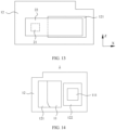
- FIG. 19 is a front view of an electronic device according to an embodiment of this application.
- the electronic device 100 includes a housing 10 and a camera module 2 connected to the housing 10.
- the electronic device 100 manufactured based on the foregoing camera module 2 is thinner, that is, an avoidance space between a decorative part 1 and a module body 22 can be eliminated.
- a part of a skirt structure 12 of the decorative part 1 is cut off, which may cause an impact of poor sealing effect.
- a sealing way of the decorative part 1 (refer to the foregoing description) is improved, so that a good sealing effect is maintained.
- FIG. 19 is only an example, in which the quantity of lens 21 of the camera module 2 is not limited to three, for example, it may be one, two, or at least three.
- the electronic device 100 may be any (for example, a mobile phone shown in FIG. 19 ) of various types of computer system devices that are mobile or portable and perform wireless communications.
- the electronic device 100 may be a mobile phone or a smartphone (for example, a phone based on iPhone TM or Android TM), a portable game device (for example, Nintendo DSTM, Play Station Portable TM, Gameboy Advance TM, or iPhone TM), a laptop computer, PDA, a portable Internet device, a music player, or a data storage device, another handheld device, a watch, an earphone, a pendant, a headset, or the like.
- the electronic device 100 may also be another wearable device (for example, electronic glasses, electronic clothes, an electronic bracelet, an electronic necklace, an electronic tattoo, or a head-mounted device of a smartwatch).
- the electronic device 100 may also be any one of a plurality of electronic devices 100.
- the plurality of electronic devices 100 include but are not limited to a cell phone, a smartphone, another wireless communications device, a personal digital assistant, an audio player, another media player, a music recorder, a video recorder, a camera, another media recorder, a radio set, a medical device, a vehicle transportation instrument, a calculator, a programmable remote control, a pager, a laptop computer, a desktop computer, a printer, a netbook computer, a personal digital assistant (PDA), a portable multimedia player (PMP), a motion picture experts group (MPEG-1 or MPEG-2) audio layer (MP3) player, a portable medical device, a digital camera, or a combination thereof.
- PDA personal digital assistant
- PMP portable multimedia player
- MPEG-1 or MPEG-2 motion picture experts group
- MP3 audio layer
Landscapes
- Engineering & Computer Science (AREA)
- Signal Processing (AREA)
- Multimedia (AREA)
- Camera Bodies And Camera Details Or Accessories (AREA)
- Studio Devices (AREA)
- Telephone Set Structure (AREA)
Claims (11)
- Dispositif électronique (100), comprenant :un logement (10), dans lequel le logement est pourvu d'un trou de montage (101) ;un module de caméra (2), dans lequel le module de caméra comprend une lentille (21) et un corps de module (22) relié à la lentille ; etune partie décorative (1), dans lequel la partie décorative comprend un corps de partie décorative (11) et une structure de jupe (12) reliée au corps de partie décorative, et le corps de partie décorative est relié, par la structure de jupe, au logement, dans lequel le corps de partie décorative est disposé sur la périphérie de la lentille et disposé dans le trou de montage, et dans lequel une projection orthographique, le long de la direction d'épaisseur du corps de module, de la partie du corps de module sur un plan de la structure de jupe ne tombe pas dans la structure de jupe, dans lequel le corps de module est opposé à l'encoche ; et dans lequel :la structure de jupe est pourvue d'une encoche (121), l'encoche est opposée à une partie du corps de module (22) ; dans lequel le long d'une direction d'épaisseur (Y) du corps de module, l'encoche passe à travers au moins une surface inférieure de la structure de jupe (12), ladite surface inférieure faisant face vers le corps de module (22) ;caractérisé en ce que le dispositif électronique comprend en outre un troisième joint d'étanchéité (33), un écartement (102) est formé entre le trou de montage et le corps de partie décorative, et l'écartement communique avec l'encoche ; etau moins une partie du troisième joint d'étanchéité est disposée dans l'encoche, et le troisième joint d'étanchéité couvre l'écartement correspondant à l'encoche.
- Dispositif électronique selon la revendication 1, dans lequel l'encoche passe à travers au moins une paroi latérale, le long d'une direction de longueur du corps de module, de la structure de jupe.
- Dispositif électronique selon la revendication 1, dans lequel, le long d'une direction de longueur du corps de module, le bord d'une projection orthographique de la partie du corps de module sur le plan de la structure de jupe ne dépasse pas le bord de l'encoche, dans lequel le corps de module est opposé à l'encoche.
- Dispositif électronique selon l'une quelconque des revendications 1 à 3, dans lequel un premier joint d'étanchéité est disposé entre le corps de module et le corps de partie décorative, et le premier joint d'étanchéité est disposé autour de la périphérie de la lentille.
- Dispositif électronique selon l'une quelconque des revendications 1 à 4, dans lequel un deuxième joint d'étanchéité est disposé entre la jupe et le logement.
- Dispositif électronique selon la revendication 1, dans lequel une projection orthographique du troisième joint d'étanchéité sur le plan de la structure de jupe ne dépasse pas le bord de l'encoche, et un matériau d'étanchéité est disposé entre le troisième joint d'étanchéité et le bord de l'encoche.
- Dispositif électronique selon l'une quelconque des revendications 1 à 6, dans lequel un écartement est réservé entre le trou de montage et le corps de partie décorative, l'écartement communique avec l'encoche, et au moins l'un parmi l'écartement et l'encoche est pourvu d'un matériau d'étanchéité.
- Dispositif électronique selon l'une quelconque des revendications 1 à 7, dans lequel la partie décorative comprend :une première partie décorative, dans lequel un quatrième joint d'étanchéité est disposé entre la première partie décorative et une paroi externe du logement, et le quatrième joint d'étanchéité est disposé autour de la périphérie du trou de montage ; etune seconde partie décorative, reliée à la première partie décorative, dans lequel la seconde partie décorative comprend la structure de jupe, et la seconde partie décorative est reliée à la fois au corps de module et au logement.
- Dispositif électronique (100) selon l'une quelconque des revendications 1 ou 2, dans lequel une région où la lentille (21) est localisée est une région d'entrée de lumière, la région d'entrée de lumière étant formée par un trou de lumière (111) du corps de partie décorative (11), et une région où le corps de module (22) est localisé est une région sans entrée de lumière.
- Dispositif électronique (100) selon la revendication 9, dans lequel la partie du corps de module (22) est localisée dans la région sans entrée de lumière.
- Dispositif électronique (100) selon l'une quelconque des revendications 1 ou 2, dans lequel la structure de jupe (12) est fixée à une paroi interne du logement (10).
Applications Claiming Priority (2)
| Application Number | Priority Date | Filing Date | Title |
|---|---|---|---|
| CN202010080473.2A CN113225453B (zh) | 2020-02-05 | 2020-02-05 | 电子设备 |
| PCT/CN2021/074618 WO2021155767A1 (fr) | 2020-02-05 | 2021-02-01 | Dispositif électronique |
Publications (3)
| Publication Number | Publication Date |
|---|---|
| EP4002827A1 EP4002827A1 (fr) | 2022-05-25 |
| EP4002827A4 EP4002827A4 (fr) | 2022-11-23 |
| EP4002827B1 true EP4002827B1 (fr) | 2024-04-24 |
Family
ID=77085646
Family Applications (1)
| Application Number | Title | Priority Date | Filing Date |
|---|---|---|---|
| EP21750378.8A Active EP4002827B1 (fr) | 2020-02-05 | 2021-02-01 | Dispositif électronique |
Country Status (4)
| Country | Link |
|---|---|
| US (1) | US20220377162A1 (fr) |
| EP (1) | EP4002827B1 (fr) |
| CN (3) | CN113225453B (fr) |
| WO (1) | WO2021155767A1 (fr) |
Families Citing this family (4)
| Publication number | Priority date | Publication date | Assignee | Title |
|---|---|---|---|---|
| CN115715063A (zh) * | 2021-08-23 | 2023-02-24 | 荣耀终端有限公司 | 装饰结构、壳体组件、电子设备及光电组件 |
| CN113810586B (zh) * | 2021-10-28 | 2023-02-17 | 维沃移动通信有限公司 | 电子设备 |
| CN115550485B (zh) * | 2022-04-24 | 2023-06-30 | 荣耀终端有限公司 | 外壳组件及电子设备 |
| CN114979450B (zh) * | 2022-07-22 | 2022-12-23 | 荣耀终端有限公司 | 一种摄像头装饰支架、摄像头装饰组件及电子设备 |
Family Cites Families (16)
| Publication number | Priority date | Publication date | Assignee | Title |
|---|---|---|---|---|
| CN201600536U (zh) * | 2010-01-29 | 2010-10-06 | 信利光电(汕尾)有限公司 | 自动对焦摄像模组 |
| CN104580861B (zh) * | 2014-12-26 | 2018-02-27 | 深圳市海蕴新能源有限公司 | 智能摄像装置 |
| CN204886938U (zh) * | 2015-09-02 | 2015-12-16 | 广东欧珀移动通信有限公司 | 一种摄像头装饰件及移动终端 |
| CN205901895U (zh) * | 2016-08-08 | 2017-01-18 | 广州三星通信技术研究有限公司 | 摄像头装饰件及包括该摄像头装饰件的电子设备 |
| JP6574796B2 (ja) * | 2017-01-31 | 2019-09-11 | 矢崎総業株式会社 | バスバー保持構造 |
| US10996713B2 (en) * | 2017-08-07 | 2021-05-04 | Apple Inc. | Portable electronic device |
| CN207234840U (zh) * | 2017-09-13 | 2018-04-13 | 深圳传音制造有限公司 | 摄像头装饰件固定结构和手机 |
| CN207491070U (zh) * | 2017-10-17 | 2018-06-12 | 广东欧珀移动通信有限公司 | 摄像头装饰件、壳体组件及终端 |
| WO2019091379A1 (fr) * | 2017-11-09 | 2019-05-16 | Guangdong Oppo Mobile Telecommunications Corp., Ltd. | Dispositif de caméra, support et terminal mobile l'utilisant |
| CN107809507B (zh) * | 2017-12-12 | 2024-02-20 | Oppo广东移动通信有限公司 | 移动终端 |
| CN108632509B (zh) * | 2018-05-10 | 2020-07-07 | Oppo广东移动通信有限公司 | 电子设备 |
| US11019242B2 (en) * | 2018-06-14 | 2021-05-25 | Guangdong Oppo Mobile Telecommunications Corp., Ltd. | Camera assembly and electronic device using the same, both having a decorative member mounted on a shell and comprising a decorative ring and a flange |
| CN112492139B (zh) * | 2018-12-24 | 2021-10-15 | 华为技术有限公司 | 摄像组件及电子设备 |
| CN110365885A (zh) * | 2019-07-29 | 2019-10-22 | Oppo广东移动通信有限公司 | 摄像头组件及电子设备 |
| CN110430346B (zh) * | 2019-07-29 | 2021-06-01 | Oppo广东移动通信有限公司 | 摄像头组件和电子装置 |
| CN110602362B (zh) * | 2019-09-18 | 2021-04-13 | Oppo广东移动通信有限公司 | 电子设备 |
-
2020
- 2020-02-05 CN CN202010080473.2A patent/CN113225453B/zh active Active
- 2020-02-05 CN CN202111568729.5A patent/CN114500793B/zh active Active
-
2021
- 2021-02-01 US US17/763,336 patent/US20220377162A1/en active Pending
- 2021-02-01 CN CN202180020444.XA patent/CN115428427A/zh active Pending
- 2021-02-01 WO PCT/CN2021/074618 patent/WO2021155767A1/fr unknown
- 2021-02-01 EP EP21750378.8A patent/EP4002827B1/fr active Active
Also Published As
| Publication number | Publication date |
|---|---|
| EP4002827A1 (fr) | 2022-05-25 |
| CN115428427A (zh) | 2022-12-02 |
| EP4002827A4 (fr) | 2022-11-23 |
| CN113225453B (zh) | 2022-02-15 |
| CN113225453A (zh) | 2021-08-06 |
| US20220377162A1 (en) | 2022-11-24 |
| CN114500793A (zh) | 2022-05-13 |
| WO2021155767A1 (fr) | 2021-08-12 |
| CN114500793B (zh) | 2023-04-07 |
Similar Documents
| Publication | Publication Date | Title |
|---|---|---|
| EP4002827B1 (fr) | Dispositif électronique | |
| KR102064596B1 (ko) | 카메라 모듈을 포함하는 전자장치 | |
| CN204989584U (zh) | 一种摄像头模组及移动设备 | |
| US11703908B2 (en) | Electronic device having sliding mechanism | |
| CN108132563B (zh) | 背光模组、显示屏及电子设备 | |
| US11044391B2 (en) | Electronic device having sliding mechanism | |
| EP3771197A1 (fr) | Support de caméra, ensemble caméra et terminal | |
| CN108234702B (zh) | 显示屏组件及电子设备 | |
| EP3817355B1 (fr) | Module de caméra et dispositif optique le comprenant | |
| WO2022262677A1 (fr) | Dispositif électronique | |
| JP2022520350A (ja) | 電子機器、表示画面アセンブリ及びカバープレート | |
| CN213585867U (zh) | 电子设备 | |
| CN203482537U (zh) | 一种电子设备 | |
| CN104717407A (zh) | 具有摄像头防尘组件的电子装置 | |
| CN110557483A (zh) | 一种伸缩机构及移动终端 | |
| CN209897468U (zh) | 密封结构及电子设备 | |
| US9122086B2 (en) | Display apparatus | |
| WO2024011991A1 (fr) | Appareil électronique | |
| CN111385452B (zh) | 一种电子设备 | |
| KR20230000361A (ko) | 보호 시트 및 이를 포함하는 카메라 모듈 | |
| TWI416243B (zh) | 攝像頭保護裝置 | |
| KR101908006B1 (ko) | 디스플레이 모듈 및 이를 구비한 휴대 단말기 |
Legal Events
| Date | Code | Title | Description |
|---|---|---|---|
| STAA | Information on the status of an ep patent application or granted ep patent |
Free format text: STATUS: THE INTERNATIONAL PUBLICATION HAS BEEN MADE |
|
| PUAI | Public reference made under article 153(3) epc to a published international application that has entered the european phase |
Free format text: ORIGINAL CODE: 0009012 |
|
| STAA | Information on the status of an ep patent application or granted ep patent |
Free format text: STATUS: REQUEST FOR EXAMINATION WAS MADE |
|
| 17P | Request for examination filed |
Effective date: 20220221 |
|
| AK | Designated contracting states |
Kind code of ref document: A1 Designated state(s): AL AT BE BG CH CY CZ DE DK EE ES FI FR GB GR HR HU IE IS IT LI LT LU LV MC MK MT NL NO PL PT RO RS SE SI SK SM TR |
|
| REG | Reference to a national code |
Ref country code: DE Ref legal event code: R079 Ref document number: 602021012377 Country of ref document: DE Free format text: PREVIOUS MAIN CLASS: H04N0005225000 Ipc: H04M0001020000 Ref country code: DE Free format text: PREVIOUS MAIN CLASS: H04N0005225000 Ipc: H04M0001020000 |
|
| A4 | Supplementary search report drawn up and despatched |
Effective date: 20221026 |
|
| RIC1 | Information provided on ipc code assigned before grant |
Ipc: H04N 5/225 20060101ALI20221020BHEP Ipc: H04M 1/02 20060101AFI20221020BHEP |
|
| DAV | Request for validation of the european patent (deleted) | ||
| DAX | Request for extension of the european patent (deleted) | ||
| STAA | Information on the status of an ep patent application or granted ep patent |
Free format text: STATUS: EXAMINATION IS IN PROGRESS |
|
| 17Q | First examination report despatched |
Effective date: 20230710 |
|
| GRAP | Despatch of communication of intention to grant a patent |
Free format text: ORIGINAL CODE: EPIDOSNIGR1 |
|
| STAA | Information on the status of an ep patent application or granted ep patent |
Free format text: STATUS: GRANT OF PATENT IS INTENDED |
|
| RIC1 | Information provided on ipc code assigned before grant |
Ipc: H04N 23/57 20230101ALI20231031BHEP Ipc: H04M 1/02 20060101AFI20231031BHEP |
|
| INTG | Intention to grant announced |
Effective date: 20231120 |
|
| GRAS | Grant fee paid |
Free format text: ORIGINAL CODE: EPIDOSNIGR3 |
|
| GRAA | (expected) grant |
Free format text: ORIGINAL CODE: 0009210 |
|
| STAA | Information on the status of an ep patent application or granted ep patent |
Free format text: STATUS: THE PATENT HAS BEEN GRANTED |
|
| AK | Designated contracting states |
Kind code of ref document: B1 Designated state(s): AL AT BE BG CH CY CZ DE DK EE ES FI FR GB GR HR HU IE IS IT LI LT LU LV MC MK MT NL NO PL PT RO RS SE SI SK SM TR |
|
| REG | Reference to a national code |
Ref country code: GB Ref legal event code: FG4D |
|
| REG | Reference to a national code |
Ref country code: CH Ref legal event code: EP |
|
| REG | Reference to a national code |
Ref country code: DE Ref legal event code: R096 Ref document number: 602021012377 Country of ref document: DE |
|
| REG | Reference to a national code |
Ref country code: IE Ref legal event code: FG4D |