EP4001893B1 - Particle detection sensor and particle detector - Google Patents
Particle detection sensor and particle detector Download PDFInfo
- Publication number
- EP4001893B1 EP4001893B1 EP21199109.6A EP21199109A EP4001893B1 EP 4001893 B1 EP4001893 B1 EP 4001893B1 EP 21199109 A EP21199109 A EP 21199109A EP 4001893 B1 EP4001893 B1 EP 4001893B1
- Authority
- EP
- European Patent Office
- Prior art keywords
- substrate
- condensing lens
- photodetector
- detection sensor
- light
- Prior art date
- Legal status (The legal status is an assumption and is not a legal conclusion. Google has not performed a legal analysis and makes no representation as to the accuracy of the status listed.)
- Active
Links
Images





Classifications
-
- G—PHYSICS
- G01—MEASURING; TESTING
- G01N—INVESTIGATING OR ANALYSING MATERIALS BY DETERMINING THEIR CHEMICAL OR PHYSICAL PROPERTIES
- G01N15/00—Investigating characteristics of particles; Investigating permeability, pore-volume or surface-area of porous materials
- G01N15/06—Investigating concentration of particle suspensions
-
- G—PHYSICS
- G01—MEASURING; TESTING
- G01N—INVESTIGATING OR ANALYSING MATERIALS BY DETERMINING THEIR CHEMICAL OR PHYSICAL PROPERTIES
- G01N15/00—Investigating characteristics of particles; Investigating permeability, pore-volume or surface-area of porous materials
- G01N15/02—Investigating particle size or size distribution
- G01N15/0205—Investigating particle size or size distribution by optical means
-
- G—PHYSICS
- G01—MEASURING; TESTING
- G01N—INVESTIGATING OR ANALYSING MATERIALS BY DETERMINING THEIR CHEMICAL OR PHYSICAL PROPERTIES
- G01N1/00—Sampling; Preparing specimens for investigation
- G01N1/02—Devices for withdrawing samples
- G01N1/22—Devices for withdrawing samples in the gaseous state
- G01N1/2273—Atmospheric sampling
-
- G—PHYSICS
- G01—MEASURING; TESTING
- G01N—INVESTIGATING OR ANALYSING MATERIALS BY DETERMINING THEIR CHEMICAL OR PHYSICAL PROPERTIES
- G01N15/00—Investigating characteristics of particles; Investigating permeability, pore-volume or surface-area of porous materials
- G01N15/10—Investigating individual particles
- G01N15/14—Optical investigation techniques, e.g. flow cytometry
- G01N15/1434—Optical arrangements
- G01N15/1436—Optical arrangements the optical arrangement forming an integrated apparatus with the sample container, e.g. a flow cell
-
- G—PHYSICS
- G01—MEASURING; TESTING
- G01N—INVESTIGATING OR ANALYSING MATERIALS BY DETERMINING THEIR CHEMICAL OR PHYSICAL PROPERTIES
- G01N21/00—Investigating or analysing materials by the use of optical means, i.e. using sub-millimetre waves, infrared, visible or ultraviolet light
- G01N21/17—Systems in which incident light is modified in accordance with the properties of the material investigated
- G01N21/47—Scattering, i.e. diffuse reflection
- G01N21/49—Scattering, i.e. diffuse reflection within a body or fluid
- G01N21/53—Scattering, i.e. diffuse reflection within a body or fluid within a flowing fluid, e.g. smoke
-
- G—PHYSICS
- G01—MEASURING; TESTING
- G01N—INVESTIGATING OR ANALYSING MATERIALS BY DETERMINING THEIR CHEMICAL OR PHYSICAL PROPERTIES
- G01N21/00—Investigating or analysing materials by the use of optical means, i.e. using sub-millimetre waves, infrared, visible or ultraviolet light
- G01N21/84—Systems specially adapted for particular applications
- G01N21/85—Investigating moving fluids or granular solids
-
- G—PHYSICS
- G01—MEASURING; TESTING
- G01N—INVESTIGATING OR ANALYSING MATERIALS BY DETERMINING THEIR CHEMICAL OR PHYSICAL PROPERTIES
- G01N15/00—Investigating characteristics of particles; Investigating permeability, pore-volume or surface-area of porous materials
- G01N15/06—Investigating concentration of particle suspensions
- G01N15/075—Investigating concentration of particle suspensions by optical means
-
- G—PHYSICS
- G01—MEASURING; TESTING
- G01N—INVESTIGATING OR ANALYSING MATERIALS BY DETERMINING THEIR CHEMICAL OR PHYSICAL PROPERTIES
- G01N15/00—Investigating characteristics of particles; Investigating permeability, pore-volume or surface-area of porous materials
- G01N2015/0042—Investigating dispersion of solids
- G01N2015/0046—Investigating dispersion of solids in gas, e.g. smoke
-
- G—PHYSICS
- G01—MEASURING; TESTING
- G01N—INVESTIGATING OR ANALYSING MATERIALS BY DETERMINING THEIR CHEMICAL OR PHYSICAL PROPERTIES
- G01N15/00—Investigating characteristics of particles; Investigating permeability, pore-volume or surface-area of porous materials
- G01N2015/03—Electro-optical investigation of a plurality of particles, the analyser being characterised by the optical arrangement
Definitions
- the present invention relates to a particle detection sensor and a particle detector.
- Examples known as a related art include a particle detection sensor that detects particles contained in a gas.
- Japanese Unexamined Patent Application Publication No. 2016-090349 discloses a particle detection sensor that can detect particles with high accuracy.
- an optical system 20 in a particle detection sensor 1 includes a phototransmitter 120 and a photoreceiver 130 disposed in a detection area DA covered with a housing 10 to have their optical axes (optical axis P and optical axis Q) cross each other.
- the photoreceiver 130 detects particles 2 that pass the detection area DA with light output by the phototransmitter 120.
- the phototransmitter 120 and the photoreceiver 130 are disposed on an inner surface of the housing 10 to have their optical axes cross at a predetermined angle.
- the particle detection sensor 1 is to have a large size, and fails to have a small size.
- EP 3 214 425 A1 discloses another known particle detection sensor which includes: a light projection system that outputs and focuses light on a detection area; a light reception system that receives scattered light, the scattered light being light from the light projection system that has been scattered by a particle in the detection area; and a first light trap disposed across the detection area from the light reception system.
- An aspect of the present disclosure is to provide a particle detection sensor with a small size.
- the present invention relates to a particle detection sensor as defined in claim 1.
- Preferred features of the invention are set out in the dependent claims.
- An aspect of the present disclosure can provide a particle detection sensor with a small size.
- Embodiment 1 of the present disclosure will be described in detail, below.
- FIG. 1 is a perspective view of the appearance of a particle detector 1 according to the present embodiment.
- the particle detector 1 is a device that detects particles in a gas.
- FIG. 2 is an exploded perspective view of a structure of the particle detector 1 according to the present embodiment.
- the particle detector 1 includes a top cover 2, an internal cover 3, a substrate 4, an air-current generation mechanism 5, a detection mechanism (particle detection sensor) 6, and a bottom cover 7.
- the top cover 2 is an upper cover and includes an inlet port 21 and an outlet port 22.
- the inlet port 21 is a port through which gas outside of the particle detector 1 is taken inside.
- the outlet port 22 is a port through which gas inside the particle detector 1 is discharged to the outside, and has a shape corresponding to an exhaust port of the air-current generation mechanism 5.
- the internal cover 3 is a cover located between (in the middle of) the top cover 2 and the bottom cover 7, and includes an inlet port 31 and an outlet port 32.
- the inlet port 31 includes an opening through which a gas outside of the particle detector 1 is taken inside, and a rectangular-prism-shaped inner surface that guides the gas to the detection mechanism 6.
- the outlet port 32 is a port through which gas inside the particle detector 1 is discharged to the outside, and has a shape corresponding to the profile of the air-current generation mechanism 5.
- the substrate 4 is a bed plate receiving components including the air-current generation mechanism 5 and the detection mechanism 6.
- the air-current generation mechanism 5 is a mechanism that is mounted on the substrate 4 and generates an air current to cause outside gas to pass through a path 9 (refer to FIG. 3 ). This mechanism can take in gas outside of the particle detector 1, cause the gas to pass through itself, and discharge the gas to the outside.
- the air-current generation mechanism 5 includes components such as a fan, a temperature regulator, and a pressure regulator. Instead of being installed inside, the air-current generation mechanism 5 may be externally connected to the particle detector 1.
- the detection mechanism 6 is a mechanism that is disposed on the substrate 4 and detects particles in gas taken in through the inlet ports 21 and 31.
- the detection mechanism 6 is described below in detail.
- the bottom cover 7 is a lower cover. As illustrated in FIG. 2 , the internal cover 3 and the bottom cover 7 cover the substrate 4, the air-current generation mechanism 5, and the detection mechanism 6. More specifically, the internal cover 3 covers components such as the air-current generation mechanism 5 and the detection mechanism 6. Screws 8 stand erect on an internal flat surface of the bottom cover 7 to support the substrate 4.
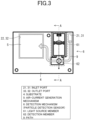
- FIG. 3 is a plan view of the substrate 4, the air-current generation mechanism 5, and the detection mechanism 6 of the particle detector 1 according to the present embodiment. As illustrated in FIG. 3 , the air-current generation mechanism 5 and the detection mechanism 6 are mounted on the substrate 4.
- the air-current generation mechanism 5 When rotating its fan, the air-current generation mechanism 5 generates a flow of gas (flow indicated with a hatched arrow in FIG. 3 ) taken in from the outside of the particle detector 1 through the inlet ports 21 and 31, passing over a detection member 62, passing through the air-current generation mechanism 5, and discharged through the outlet ports 32 and 22 to the outside of the particle detector 1.
- a flow of gas flow indicated with a hatched arrow in FIG. 3
- the detection mechanism 6 includes a light source member 61 and a detection member 62.
- the light source member 61 is disposed parallel to the plane of the substrate 4, and emits light toward above the detection member 62 (in a direction indicated with a broken arrow in FIG. 3 ).
- the detection member 62 is disposed at a position toward which light from the light source member 61 is emitted, and detects scattering light obtained by the emitted light scattered by particles in a gas.
- the particle detector 1 includes a path 9 disposed above at least the detection member 62 (condensing lens), including a space through which light emitted from the light source member 61 (light source) passes, and allowing the outside gas to pass therethrough.
- the gas taken in from the outside of the particle detector 1 with the operation of the air-current generation mechanism 5 receives light emitted from the light source member 61 when passing above the detection member 62. At this time, particles contained in the gas scatter light from the light source member 61.
- the detection member 62 detects part of the scattering light. Thus, particles in the gas can be detected.
- FIG. 4 is a perspective view of a structure of the detection mechanism 6 according to the present embodiment.
- the detection mechanism 6 includes the light source member 61 and the detection member 62.
- the light source member 61 is disposed on the substrate 4, and includes a wall 611, grooves 612, a light source 613, and a projection lens 614.
- the wall 611 forms a housing of the light source member 61.
- the grooves 612 are formed on the inner surface of the wall 611 to hold the projection lens 614 therebetween.
- the light source 613 is disposed on the substrate 4, and emits light toward at least the projection lens 614.
- the projection lens 614 is a lens to converge light emitted from the light source 613 to irradiate a portion above the detection member 62 with the light.
- the projection lens 614 is disposed perpendicularly to the substrate 4 while being held between the grooves 612.
- the detection member 62 is disposed adjacent to the light source member 61, and includes a condensing lens 621, a photodetector 622, a holder 623, and a hole 624.
- the condensing lens 621 is a lens that converges light received from above the condensing lens 621 and to irradiate the photodetector 622 with the light.
- the condensing lens 621 is disposed between the substrate 4 and light emitted from the light source 613. Specifically, the condensing lens 621 is disposed opposite the light source 613 across the projection lens 614, below the light emitted from the light source 613 and that has passed through the projection lens 614, and parallel to the substrate 4. More specifically, the condenser surface of the condensing lens 621 is disposed substantially parallel to the surface of the substrate 4.
- the condensing lens 621 may be removable.
- the condensing lens 621 that is removable is cleanable and replaceable when degraded.
- the condensing lens 621 may be spherical.
- the condensing lens 621 that is spherical less easily allows falling dust to adhere thereto or accumulate thereon.
- the photodetector 622 detects light with which dust (particles) is irradiated when the light travels through the condensing lens 621 from above the condensing lens 621 to below the condensing lens 621.
- the photodetector 622 is disposed on the substrate 4 below the condensing lens 621.
- FIG. 5 is a cross-sectional view illustrating a cross section (cross section taken along line A-A in FIG. 3 ) of the detection mechanism 6 according to the present embodiment. As illustrated in FIG. 5 , the condensing lens 621 and the photodetector 622 are disposed on the substrate 4.
- the photodetector 622 is more likely to become dirty through continuous duty. However, in the above structure, the condensing lens 621 disposed above the photodetector 622 can protect the photodetector 622.
- the condensing lens 621 and the photodetector 622 may be integrated together.
- the positional relationship between the condensing lens 621 and the photodetector 622 is fixed, and thus the accuracy in particle detection is improved.
- this structure eliminates the process of assembling the condensing lens 621 and the photodetector 622 together, and thus simplifies the process of manufacturing the detection mechanism 6.
- the holder 623 is a cover covering the condensing lens 621 and the photodetector 622.
- the hole 624 is formed at an upper portion in the holder 623 to limit light that is to pass through the condensing lens 621.
- providing the holder 623 can narrow light that is to pass through the condensing lens 621, and thus can reduce stray light.
- This structure can block light that fails to be condensed by the condensing lens 621, and thus can improve the detection accuracy. Dust accumulating on the holder 623 is less likely to enter the holder 623, and less likely to cause measurement errors.
- the holder 623 also serves as a cover of the condensing lens 621 and the photodetector 622.
- the holder 623 may include metal.
- the holder 623 including metal has a shielding effect. This structure can thus reduce the effect of electromagnetic wave noise in particle detection.
- the detection member 62 can be fixed. This can improve the positioning accuracy, prevent displacement during manufacturing, and reduce shakes (vibrations) in operation. This structure can also clearly distinguish the detection member 62 and a gas flow path (path 9), and thus can form a flow path through which gas flows smoothly.
- the directivity of the detection member 62 can be further limited. For example, narrowing the hole 624 further than the directivity (for example, ⁇ 60°) of the condensing lens 621 and the photodetector 622 enables further narrowing of the directivity.
- This structure can also block stray light that is incident on the photodetector 622 from a side surface without passing through the condensing lens 621. Forming a recess in the upper surface of the holder 623 can narrow light from the light source 613 to only the directivity of the vertical plane.
- the directivity of a horizontal plane may be as wide as possible.
- the holder 623 has a ground potential to have a shielding effect. This structure can thus reduce the effect of the disturbance noise.
- the condensing lens 621 that does not protrude from the hole 624 of the holder 623 is not directly irradiated with light. Thus, stray light can be reduced.
- the condensing lens 621 protrudes from the hole 624 of the holder 623
- the directivity of the condensing lens 621 is not limited by the hole 624 of the holder 623 (that is, the viewing angle of the condensing lens 621 can be widened).
- the condensing lens 621 closes up the hole 624, and thus prevents accumulation of dust (and, reduction of amount of light received) in the holder 623.
- the detection member 62 may exclude the holder 623. This structure limits the particle detection area not by the holder 623 but by the condensing lens 621, and thus can soften the attachment accuracy. Examples of the attachment accuracy include the position and the angle of the light source 613 and the positional relationship between the holder 623 and the photodetector 622.
- the substrate 4 of the detection mechanism 6 also includes a controller (not illustrated).
- the controller obtains signals from the photodetector 622, and detects the particle density in a gas.
- the method for detecting the particle density has some examples.
- the controller may detect the particle density by counting the light scattered from the particles.
- the controller may detect the particle density at each particle diameter by counting light scattered from the particles at each appropriate peak-value range.
- the controller may detect the particle density by averaging the received signals of the light scattered from particles.
- the light source member 61 and the detection member 62 have a simple positional relationship.
- the particle detector 1 and the detection mechanism 6 can have a small size.
- the condensing lens 621 is disposed above the photodetector 622, and thus can protect the photodetector 622.
- the condensing lens 621 facilitates its maintenance.
- the condensing lens 621 is disposed parallel to the substrate 4 not to detect signals outside of the detection area.
- Embodiment 2 of the present disclosure will be described below.
- components having the same functions as those described in Embodiment 1 are denoted with the same reference signs without being described redundantly.
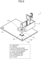
- FIG. 6 is a perspective view of a structure of a detection mechanism 6 according to the present embodiment.
- the detection mechanism 6 includes the light source member 61 and the detection member 62.
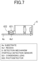
- FIG. 7 is a cross-sectional view illustrating a cross section (cross section taken along line A-A in FIG. 3 ) of the detection mechanism 6 according to the present embodiment.
- a substrate 4a has a recess 4a1.
- the photodetector 622 is embedded in the recess 4a1.
- the photodetector 622 may be a surface-mount photodetector or another type of photodetector.
- the photodetector 622 is embedded in the recess 4a1 of the substrate 4a.
- the particle detector 1 and the detection mechanism 6 can be thinned.
- This structure can secure a gas flow path.
- the photodetector 622 is securely fixed, and thus the positional accuracy of the photodetector 622 can be improved.
- the structure does not include the holder 623, the upper protrusion protruding from the substrate 4a is smaller, and thus less likely to allow dust to accumulate thereon.
- adding a spacer can flexibly adjust the height of the photodetector 622.
- Embodiment 3 of the present disclosure will be described below.
- components having the same functions as those described in Embodiments 1 and 2 are denoted with the same reference signs without being described redundantly.
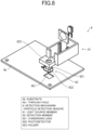
- FIG. 8 is a perspective view of a structure of a detection mechanism 6 according to the present embodiment.
- the detection mechanism 6 includes a light source member 61 and a detection member 62.
- FIG. 9 is a cross-sectional view illustrating a cross section (cross section taken along line A-A in FIG. 3 ) of the detection mechanism 6 according to the present embodiment.
- a substrate 4b has a through-hole 4b1.
- the photodetector 622 extends through the through-hole 4b1.
- the photodetector 622 may be a surface-mount photodetector or another type of photodetector.
- the photodetector 622 extends through the through-hole 4b1 in the substrate 4b.
- the particle detector 1 and the detection mechanism 6 can be further thinned.
- the gas flow path can thus be secured.
- the photodetector 622 can be reliably fixed, and the positional accuracy of the photodetector 622 can thus be improved.
- the photodetector 622 is guided into the through-hole 4b1 in the substrate 4b, and can thus be easily and accurately mounted.
- the upward protrusion protruding from the substrate 4b has its size reduced, and is thus less likely to allow dust to accumulate thereon.
- This structure allows a lead wire of the photodetector 622 to be drawn out from below the substrate 4b, and facilitates electrical connection to be flexible.
- the photodetector 622 may be bonded to the bottom side of the substrate 4b, and only the condensing lens 621 may be protruded from the through-hole 4b1.
- This structure enables an attachment of the photodetector 622 of a lead type, and can improve the productivity.
- the photodetector 622 of a lead type includes a lead wire, and the lead wire and the bottom surface of the substrate 4b are soldered. Thus, a package including the photodetector 622 that is not a surface-mount photodetector can be mounted.
- FIG. 9 illustrates a structure where the condensing lens 621 and the photodetector 622 are integrated, but the condensing lens 621 and the photodetector 622 may not be integrated together as needed.
- the structure where the photodetector 622 and the condensing lens 621 are integrated can thin the detection mechanism 6 further than the structure where the photodetector 622 and the condensing lens 621 are not integrated.
- Embodiment 4 of the present disclosure will be described below.
- components having the same functions as those described in Embodiments 1 to 3 are denoted with the same reference signs without being described redundantly.
- FIG. 10 is a cross-sectional view illustrating a horizontal cross section of a particle detector 1 according to the present embodiment.
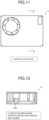
- FIG. 11 is a plan view of the particle detector 1 according to the present embodiment.
- FIG. 12 is a cross-sectional view of a cross section (cross section taken along line B-B in FIG. 11 ) of the detection mechanism 6 according to the present embodiment.
- the upper portion of the holder 623 may be omitted. Omitting the upper portion of the holder 623 simplifies the structure and facilitates the maintenance. In addition, omitting the upper portion widens the viewing angle of the photodetector 622, and widens the detection range (area) of the scattering light.
- a wall of the air-current generation mechanism 5, the wall 611 of the light source member 61, and the holder 623 have different heights. More specifically, the holder 623 is lower than the wall of the air-current generation mechanism 5 and the wall 611 of the light source member 61.
- This structure forms a gas flow path (path 9), and implements a smooth gas flow. This structure can also reduce scattering light (stray light).
- the periphery of the photodetector 622 may be covered with a conductive resin or sheet metal. This structure can reduce the effect of extraneous noise.
Landscapes
- Chemical & Material Sciences (AREA)
- Health & Medical Sciences (AREA)
- Life Sciences & Earth Sciences (AREA)
- General Physics & Mathematics (AREA)
- Physics & Mathematics (AREA)
- Analytical Chemistry (AREA)
- Biochemistry (AREA)
- General Health & Medical Sciences (AREA)
- Immunology (AREA)
- Pathology (AREA)
- Dispersion Chemistry (AREA)
- Engineering & Computer Science (AREA)
- Biomedical Technology (AREA)
- Molecular Biology (AREA)
- Investigating Or Analysing Materials By Optical Means (AREA)
- Investigating Or Analysing Materials By The Use Of Chemical Reactions (AREA)
Description
- The present invention relates to a particle detection sensor and a particle detector.
- Examples known as a related art include a particle detection sensor that detects particles contained in a gas. For example,
Japanese Unexamined Patent Application Publication No. 2016-090349 FIG. 4 inJapanese Unexamined Patent Application Publication No. 2016-090349 particle detection sensor 1 includes a phototransmitter 120 and a photoreceiver 130 disposed in a detection area DA covered with a housing 10 to have their optical axes (optical axis P and optical axis Q) cross each other. The photoreceiver 130 detectsparticles 2 that pass the detection area DA with light output by the phototransmitter 120. - In the above example of the related art, however, the phototransmitter 120 and the photoreceiver 130 are disposed on an inner surface of the housing 10 to have their optical axes cross at a predetermined angle. To implement such a structure, the
particle detection sensor 1 is to have a large size, and fails to have a small size. -
EP 3 214 425 A1 discloses another known particle detection sensor which includes: a light projection system that outputs and focuses light on a detection area; a light reception system that receives scattered light, the scattered light being light from the light projection system that has been scattered by a particle in the detection area; and a first light trap disposed across the detection area from the light reception system. - An aspect of the present disclosure is to provide a particle detection sensor with a small size.
- To address the above problem, the present invention relates to a particle detection sensor as defined in
claim 1. Preferred features of the invention are set out in the dependent claims. - An aspect of the present disclosure can provide a particle detection sensor with a small size.
-
-
FIG. 1 is a perspective view of the appearance of a particle detector according toEmbodiment 1 of the present disclosure; -
FIG. 2 is an exploded perspective view of a structure of the particle detector according toEmbodiment 1 of the present disclosure; -
FIG. 3 is a plan view of a substrate, an air-current generation mechanism, and a detection mechanism of the particle detector according toEmbodiment 1 of the present disclosure; -
FIG. 4 is a perspective view of a structure of the detection mechanism according toEmbodiment 1 of the present disclosure; -
FIG. 5 is a cross-sectional view of the detection mechanism according toEmbodiment 1 of the present disclosure; -
FIG. 6 is a perspective view of a structure of a detection mechanism according toEmbodiment 2 of the present disclosure; -
FIG. 7 is a cross-sectional view of the detection mechanism according toEmbodiment 2 of the present disclosure; -
FIG. 8 is a perspective view of a structure of a detection mechanism according toEmbodiment 3 of the present disclosure; -
FIG. 9 is a cross-sectional view of the detection mechanism according toEmbodiment 3 of the present disclosure; -
FIG. 10 is a cross-sectional view of a particle detector according toEmbodiment 4 of the present disclosure; -
FIG. 11 is a plan view of the particle detector according toEmbodiment 4 of the present disclosure; and -
FIG. 12 is a cross-sectional view of a detection mechanism according toEmbodiment 4 of the present disclosure. -
Embodiment 1 of the present disclosure will be described in detail, below. -
FIG. 1 is a perspective view of the appearance of aparticle detector 1 according to the present embodiment. Theparticle detector 1 is a device that detects particles in a gas. -
FIG. 2 is an exploded perspective view of a structure of theparticle detector 1 according to the present embodiment. As illustrated inFIG. 2 , theparticle detector 1 includes atop cover 2, aninternal cover 3, asubstrate 4, an air-current generation mechanism 5, a detection mechanism (particle detection sensor) 6, and abottom cover 7. - The
top cover 2 is an upper cover and includes aninlet port 21 and anoutlet port 22. Theinlet port 21 is a port through which gas outside of theparticle detector 1 is taken inside. Theoutlet port 22 is a port through which gas inside theparticle detector 1 is discharged to the outside, and has a shape corresponding to an exhaust port of the air-current generation mechanism 5. - The
internal cover 3 is a cover located between (in the middle of) thetop cover 2 and thebottom cover 7, and includes aninlet port 31 and anoutlet port 32. Theinlet port 31 includes an opening through which a gas outside of theparticle detector 1 is taken inside, and a rectangular-prism-shaped inner surface that guides the gas to thedetection mechanism 6. Theoutlet port 32 is a port through which gas inside theparticle detector 1 is discharged to the outside, and has a shape corresponding to the profile of the air-current generation mechanism 5. - The
substrate 4 is a bed plate receiving components including the air-current generation mechanism 5 and thedetection mechanism 6. The air-current generation mechanism 5 is a mechanism that is mounted on thesubstrate 4 and generates an air current to cause outside gas to pass through a path 9 (refer toFIG. 3 ). This mechanism can take in gas outside of theparticle detector 1, cause the gas to pass through itself, and discharge the gas to the outside. The air-current generation mechanism 5 includes components such as a fan, a temperature regulator, and a pressure regulator. Instead of being installed inside, the air-current generation mechanism 5 may be externally connected to theparticle detector 1. - The
detection mechanism 6 is a mechanism that is disposed on thesubstrate 4 and detects particles in gas taken in through theinlet ports detection mechanism 6 is described below in detail. - The
bottom cover 7 is a lower cover. As illustrated inFIG. 2 , theinternal cover 3 and thebottom cover 7 cover thesubstrate 4, the air-current generation mechanism 5, and thedetection mechanism 6. More specifically, theinternal cover 3 covers components such as the air-current generation mechanism 5 and thedetection mechanism 6.Screws 8 stand erect on an internal flat surface of thebottom cover 7 to support thesubstrate 4. -
FIG. 3 is a plan view of thesubstrate 4, the air-current generation mechanism 5, and thedetection mechanism 6 of theparticle detector 1 according to the present embodiment. As illustrated inFIG. 3 , the air-current generation mechanism 5 and thedetection mechanism 6 are mounted on thesubstrate 4. - When rotating its fan, the air-
current generation mechanism 5 generates a flow of gas (flow indicated with a hatched arrow inFIG. 3 ) taken in from the outside of theparticle detector 1 through theinlet ports detection member 62, passing through the air-current generation mechanism 5, and discharged through theoutlet ports particle detector 1. - The
detection mechanism 6 includes alight source member 61 and adetection member 62. Thelight source member 61 is disposed parallel to the plane of thesubstrate 4, and emits light toward above the detection member 62 (in a direction indicated with a broken arrow inFIG. 3 ). Thedetection member 62 is disposed at a position toward which light from thelight source member 61 is emitted, and detects scattering light obtained by the emitted light scattered by particles in a gas. - The
particle detector 1 includes apath 9 disposed above at least the detection member 62 (condensing lens), including a space through which light emitted from the light source member 61 (light source) passes, and allowing the outside gas to pass therethrough. - In the above structure, the gas taken in from the outside of the
particle detector 1 with the operation of the air-current generation mechanism 5 receives light emitted from thelight source member 61 when passing above thedetection member 62. At this time, particles contained in the gas scatter light from thelight source member 61. Thedetection member 62 detects part of the scattering light. Thus, particles in the gas can be detected. - The cross-sectional view taken along line A-A corresponds to embodiments described below.
-
FIG. 4 is a perspective view of a structure of thedetection mechanism 6 according to the present embodiment. Thedetection mechanism 6 includes thelight source member 61 and thedetection member 62. - As illustrated in
FIG. 4 , thelight source member 61 is disposed on thesubstrate 4, and includes awall 611,grooves 612, alight source 613, and aprojection lens 614. Thewall 611 forms a housing of thelight source member 61. Thegrooves 612 are formed on the inner surface of thewall 611 to hold theprojection lens 614 therebetween. Thelight source 613 is disposed on thesubstrate 4, and emits light toward at least theprojection lens 614. Theprojection lens 614 is a lens to converge light emitted from thelight source 613 to irradiate a portion above thedetection member 62 with the light. Theprojection lens 614 is disposed perpendicularly to thesubstrate 4 while being held between thegrooves 612. - The
detection member 62 is disposed adjacent to thelight source member 61, and includes a condensinglens 621, aphotodetector 622, aholder 623, and ahole 624. - The condensing
lens 621 is a lens that converges light received from above the condensinglens 621 and to irradiate thephotodetector 622 with the light. The condensinglens 621 is disposed between thesubstrate 4 and light emitted from thelight source 613. Specifically, the condensinglens 621 is disposed opposite thelight source 613 across theprojection lens 614, below the light emitted from thelight source 613 and that has passed through theprojection lens 614, and parallel to thesubstrate 4. More specifically, the condenser surface of the condensinglens 621 is disposed substantially parallel to the surface of thesubstrate 4. - The condensing
lens 621 may be removable. The condensinglens 621 that is removable is cleanable and replaceable when degraded. - The condensing
lens 621 may be spherical. The condensinglens 621 that is spherical less easily allows falling dust to adhere thereto or accumulate thereon. - The
photodetector 622 detects light with which dust (particles) is irradiated when the light travels through the condensinglens 621 from above the condensinglens 621 to below the condensinglens 621. Thephotodetector 622 is disposed on thesubstrate 4 below the condensinglens 621.FIG. 5 is a cross-sectional view illustrating a cross section (cross section taken along line A-A inFIG. 3 ) of thedetection mechanism 6 according to the present embodiment. As illustrated inFIG. 5 , the condensinglens 621 and thephotodetector 622 are disposed on thesubstrate 4. - The
photodetector 622 is more likely to become dirty through continuous duty. However, in the above structure, the condensinglens 621 disposed above thephotodetector 622 can protect thephotodetector 622. - The condensing
lens 621 and thephotodetector 622 may be integrated together. In this structure, the positional relationship between the condensinglens 621 and thephotodetector 622 is fixed, and thus the accuracy in particle detection is improved. Moreover, this structure eliminates the process of assembling the condensinglens 621 and thephotodetector 622 together, and thus simplifies the process of manufacturing thedetection mechanism 6. - The
holder 623 is a cover covering the condensinglens 621 and thephotodetector 622. Thehole 624 is formed at an upper portion in theholder 623 to limit light that is to pass through the condensinglens 621. - In the above structure, providing the
holder 623 can narrow light that is to pass through the condensinglens 621, and thus can reduce stray light. This structure can block light that fails to be condensed by the condensinglens 621, and thus can improve the detection accuracy. Dust accumulating on theholder 623 is less likely to enter theholder 623, and less likely to cause measurement errors. In other words, theholder 623 also serves as a cover of the condensinglens 621 and thephotodetector 622. - The
holder 623 may include metal. Theholder 623 including metal has a shielding effect. This structure can thus reduce the effect of electromagnetic wave noise in particle detection. - Effects of the
detection member 62 including theholder 623 will be described below. - The
detection member 62 can be fixed. This can improve the positioning accuracy, prevent displacement during manufacturing, and reduce shakes (vibrations) in operation. This structure can also clearly distinguish thedetection member 62 and a gas flow path (path 9), and thus can form a flow path through which gas flows smoothly. - The directivity of the
detection member 62 can be further limited. For example, narrowing thehole 624 further than the directivity (for example, ±60°) of the condensinglens 621 and thephotodetector 622 enables further narrowing of the directivity. This structure can also block stray light that is incident on thephotodetector 622 from a side surface without passing through the condensinglens 621. Forming a recess in the upper surface of theholder 623 can narrow light from thelight source 613 to only the directivity of the vertical plane. Here, the directivity of a horizontal plane may be as wide as possible. - The
holder 623 has a ground potential to have a shielding effect. This structure can thus reduce the effect of the disturbance noise. - The condensing
lens 621 that does not protrude from thehole 624 of theholder 623 is not directly irradiated with light. Thus, stray light can be reduced. - When, on the other hand, the condensing
lens 621 protrudes from thehole 624 of theholder 623, the directivity of the condensinglens 621 is not limited by thehole 624 of the holder 623 (that is, the viewing angle of the condensinglens 621 can be widened). In this structure, the condensinglens 621 closes up thehole 624, and thus prevents accumulation of dust (and, reduction of amount of light received) in theholder 623. - The
detection member 62 may exclude theholder 623. This structure limits the particle detection area not by theholder 623 but by the condensinglens 621, and thus can soften the attachment accuracy. Examples of the attachment accuracy include the position and the angle of thelight source 613 and the positional relationship between theholder 623 and thephotodetector 622. - The
substrate 4 of thedetection mechanism 6 also includes a controller (not illustrated). The controller obtains signals from thephotodetector 622, and detects the particle density in a gas. The method for detecting the particle density has some examples. For example, the controller may detect the particle density by counting the light scattered from the particles. The controller may detect the particle density at each particle diameter by counting light scattered from the particles at each appropriate peak-value range. Alternatively, the controller may detect the particle density by averaging the received signals of the light scattered from particles. - According to the present embodiment, the
light source member 61 and thedetection member 62 have a simple positional relationship. Thus, theparticle detector 1 and thedetection mechanism 6 can have a small size. In thedetection member 62, the condensinglens 621 is disposed above thephotodetector 622, and thus can protect thephotodetector 622. When the condensinglens 621 is removable, the condensinglens 621 facilitates its maintenance. The condensinglens 621 is disposed parallel to thesubstrate 4 not to detect signals outside of the detection area. -
Embodiment 2 of the present disclosure will be described below. For illustration convenience, components having the same functions as those described inEmbodiment 1 are denoted with the same reference signs without being described redundantly. -
FIG. 6 is a perspective view of a structure of adetection mechanism 6 according to the present embodiment. Thedetection mechanism 6 includes thelight source member 61 and thedetection member 62. -
FIG. 7 is a cross-sectional view illustrating a cross section (cross section taken along line A-A inFIG. 3 ) of thedetection mechanism 6 according to the present embodiment. - As illustrated in
FIGs. 6 and7 , asubstrate 4a has a recess 4a1. Thephotodetector 622 is embedded in the recess 4a1. Thephotodetector 622 may be a surface-mount photodetector or another type of photodetector. - In the present embodiment, the
photodetector 622 is embedded in the recess 4a1 of thesubstrate 4a. Thus, theparticle detector 1 and thedetection mechanism 6 can be thinned. - This structure can secure a gas flow path. In addition, the
photodetector 622 is securely fixed, and thus the positional accuracy of thephotodetector 622 can be improved. Although the structure does not include theholder 623, the upper protrusion protruding from thesubstrate 4a is smaller, and thus less likely to allow dust to accumulate thereon. - In addition, adding a spacer can flexibly adjust the height of the
photodetector 622. -
Embodiment 3 of the present disclosure will be described below. For illustration convenience, components having the same functions as those described inEmbodiments -
FIG. 8 is a perspective view of a structure of adetection mechanism 6 according to the present embodiment. Thedetection mechanism 6 includes alight source member 61 and adetection member 62. -
FIG. 9 is a cross-sectional view illustrating a cross section (cross section taken along line A-A inFIG. 3 ) of thedetection mechanism 6 according to the present embodiment. - As illustrated in
FIGs. 8 and9 , asubstrate 4b has a through-hole 4b1. Thephotodetector 622 extends through the through-hole 4b1. Thephotodetector 622 may be a surface-mount photodetector or another type of photodetector. - According to the present embodiment, the
photodetector 622 extends through the through-hole 4b1 in thesubstrate 4b. Thus, theparticle detector 1 and thedetection mechanism 6 can be further thinned. The gas flow path can thus be secured. In addition, thephotodetector 622 can be reliably fixed, and the positional accuracy of thephotodetector 622 can thus be improved. Thephotodetector 622 is guided into the through-hole 4b1 in thesubstrate 4b, and can thus be easily and accurately mounted. - Although having no
holder 623, the upward protrusion protruding from thesubstrate 4b has its size reduced, and is thus less likely to allow dust to accumulate thereon. This structure allows a lead wire of thephotodetector 622 to be drawn out from below thesubstrate 4b, and facilitates electrical connection to be flexible. - In the manufacturing process, the
photodetector 622 may be bonded to the bottom side of thesubstrate 4b, and only the condensinglens 621 may be protruded from the through-hole 4b1. This structure enables an attachment of thephotodetector 622 of a lead type, and can improve the productivity. Thephotodetector 622 of a lead type includes a lead wire, and the lead wire and the bottom surface of thesubstrate 4b are soldered. Thus, a package including thephotodetector 622 that is not a surface-mount photodetector can be mounted. -
FIG. 9 illustrates a structure where the condensinglens 621 and thephotodetector 622 are integrated, but the condensinglens 621 and thephotodetector 622 may not be integrated together as needed. The structure where thephotodetector 622 and the condensinglens 621 are integrated can thin thedetection mechanism 6 further than the structure where thephotodetector 622 and the condensinglens 621 are not integrated. -
Embodiment 4 of the present disclosure will be described below. For illustration convenience, components having the same functions as those described inEmbodiments 1 to 3 are denoted with the same reference signs without being described redundantly. -
FIG. 10 is a cross-sectional view illustrating a horizontal cross section of aparticle detector 1 according to the present embodiment. -
FIG. 11 is a plan view of theparticle detector 1 according to the present embodiment. -
FIG. 12 is a cross-sectional view of a cross section (cross section taken along line B-B inFIG. 11 ) of thedetection mechanism 6 according to the present embodiment. - For example, as illustrated in
FIG. 12 , the upper portion of theholder 623 may be omitted. Omitting the upper portion of theholder 623 simplifies the structure and facilitates the maintenance. In addition, omitting the upper portion widens the viewing angle of thephotodetector 622, and widens the detection range (area) of the scattering light. - Subsequently, as illustrated in
FIG. 10 , a wall of the air-current generation mechanism 5, thewall 611 of thelight source member 61, and theholder 623 have different heights. More specifically, theholder 623 is lower than the wall of the air-current generation mechanism 5 and thewall 611 of thelight source member 61. This structure forms a gas flow path (path 9), and implements a smooth gas flow. This structure can also reduce scattering light (stray light). - The periphery of the
photodetector 622 may be covered with a conductive resin or sheet metal. This structure can reduce the effect of extraneous noise. - While there have been described what are at present considered to be certain embodiments of the disclosure, it will be understood that various modifications may be made thereto, and it is intended that the appended claims cover all such modifications as fall within the scope of the present invention.
- It should be understood by those skilled in the art that various modifications, combinations, subcombinations and alterations may occur depending on design requirements and other factors insofar as they are within the scope of the appended claims.
Claims (11)
- A particle detection sensor (6) that is disposed on a substrate (4) to detect particles in a gas, the particle detection sensor (6) comprising:a substrate (4);a light source member (61) disposed on the substrate (4) and configured to emit light parallel to the substrate (4) and toward a flow path through which gas containing the particles flows;a condensing lens (621) attached to the substrate (4) and disposed between the substrate (4) and light emitted from the light source member (61) as well as configured to allow light scattered by the particles to pass through;a photodetector (622) disposed on the substrate (4) and under the condensing lens (621) as well as configured to detect light that has passed through the condensing lens (621);characterised in thatthe condensing lens (621) is disposed parallel to the substrate (4).
- The particle detection sensor (6) according to Claim 1,wherein the substrate (4) has a through-hole (4b1) configured to fix the photodetector (622), andwherein the photodetector (622) extends through the through-hole (4b1).
- The particle detection sensor (6) according to Claim 1,wherein the substrate (4) has a recess (4a1) configured to fix the photodetector (622), andwherein the photodetector (622) is embedded in the recess (4a1).
- The particle detection sensor (6) according to any one of Claims 1 to 3, wherein the condensing lens (621) and the photodetector (622) are assembled together so that a positional relationship between the condensing lens (621) and the photodetector (622) is fixed.
- The particle detection sensor (6) according to any one of Claims 1 to 4, wherein the condensing lens (621) is removable from the substrate (4).
- The particle detection sensor (6) according to any one of Claims 1 to 5, wherein the condensing lens (621) is spherical.
- The particle detection sensor (6) according to any one of Claims 1 to 6, further comprising a holder (623) that covers the condensing lens (621) and the photodetector (622) as well as that includes a hole (624) formed to limit light that is to pass through the condensing lens (621).
- The particle detection sensor (6) according to Claim 7, wherein the holder (623) includes metal.
- The particle detection sensor (6) according to any one of Claims 1 to 8, further comprising a projection lens (614) disposed perpendicularly to the substrate (4),
wherein the condensing lens (621) is disposed opposite the light source member (61) across the projection lens (614), and under light that is emitted from the light source member (61) and that has passed through the projection lens (614). - The particle detection sensor (6) according to any one of Claims 1 to 9, further comprising a path that is disposed above at least the condensing lens (621), that includes a space through which the light passes, and that allows the gas to pass therethrough.
- A particle detector (1), comprising:the particle detection sensor (6) according to Claim 10; andan air-current generation mechanism (5) that generates an air current to cause the gas to pass through the path.
Applications Claiming Priority (1)
| Application Number | Priority Date | Filing Date | Title |
|---|---|---|---|
| JP2020166199A JP7440390B2 (en) | 2020-09-30 | 2020-09-30 | Particle detection sensor and particle detection device |
Publications (3)
| Publication Number | Publication Date |
|---|---|
| EP4001893A2 EP4001893A2 (en) | 2022-05-25 |
| EP4001893A3 EP4001893A3 (en) | 2022-07-27 |
| EP4001893B1 true EP4001893B1 (en) | 2023-08-30 |
Family
ID=77998715
Family Applications (1)
| Application Number | Title | Priority Date | Filing Date |
|---|---|---|---|
| EP21199109.6A Active EP4001893B1 (en) | 2020-09-30 | 2021-09-27 | Particle detection sensor and particle detector |
Country Status (5)
| Country | Link |
|---|---|
| US (2) | US11774345B2 (en) |
| EP (1) | EP4001893B1 (en) |
| JP (1) | JP7440390B2 (en) |
| KR (3) | KR102631284B1 (en) |
| CN (1) | CN114324089A (en) |
Families Citing this family (1)
| Publication number | Priority date | Publication date | Assignee | Title |
|---|---|---|---|---|
| WO2024073551A1 (en) * | 2022-09-28 | 2024-04-04 | Dust Company, Inc. | Settled dust measurement system using photoresistors |
Family Cites Families (35)
| Publication number | Priority date | Publication date | Assignee | Title |
|---|---|---|---|---|
| US3708675A (en) * | 1969-09-19 | 1973-01-02 | Furukawa Electric Co Ltd | Smoke detector in which air entrance and egress are located in oppositely disposed surfaces which are shaped to cause an air velocity differential |
| US4616928A (en) * | 1984-06-20 | 1986-10-14 | Kidde, Inc. | Photoelectric smoke detector with adjustable background signal |
| JPH04160696A (en) * | 1990-10-25 | 1992-06-03 | Matsushita Electric Works Ltd | Photoelectric smoke sensor |
| US5262841A (en) * | 1991-10-16 | 1993-11-16 | Tsi Incorporated | Vacuum particle detector |
| JPH05190890A (en) * | 1992-01-16 | 1993-07-30 | Sharp Corp | Optically coupled device |
| JP3460494B2 (en) | 1997-02-21 | 2003-10-27 | 松下電工株式会社 | Photoelectric smoke detector |
| JP4157212B2 (en) * | 1999-02-15 | 2008-10-01 | 松下電工株式会社 | Light scattering particle detection sensor |
| JP3747763B2 (en) * | 2000-09-29 | 2006-02-22 | 松下電工株式会社 | Photoelectric smoke detector |
| JP2002352347A (en) * | 2001-05-28 | 2002-12-06 | Matsushita Electric Works Ltd | Fire detector |
| TWI235965B (en) | 2001-04-24 | 2005-07-11 | Matsushita Electric Works Ltd | Fire detector unit |
| JP2003279471A (en) * | 2002-03-20 | 2003-10-02 | Nippon Sheet Glass Co Ltd | Chip for microchemical system and microchemical system |
| WO2004104959A2 (en) * | 2003-05-23 | 2004-12-02 | Apollo Fire Detectors Limited | Smoke detector |
| JP4349978B2 (en) * | 2004-06-17 | 2009-10-21 | シチズン電子株式会社 | Optical semiconductor package and manufacturing method thereof |
| JP4241740B2 (en) * | 2006-01-26 | 2009-03-18 | シスメックス株式会社 | Sample measurement method |
| JP4877239B2 (en) * | 2006-03-28 | 2012-02-15 | パナソニック電工株式会社 | Method for manufacturing light emitting device |
| JP2008159942A (en) * | 2006-12-25 | 2008-07-10 | Matsushita Electric Works Ltd | Object detection sensor |
| JP2008250179A (en) * | 2007-03-30 | 2008-10-16 | Fujinon Corp | Dustproof structure for optical equipment |
| JP4621748B2 (en) * | 2008-02-28 | 2011-01-26 | シャープ株式会社 | Solid-state imaging device and electronic apparatus including the same |
| JP2014006108A (en) * | 2012-06-22 | 2014-01-16 | Azbil Corp | Optical particle detection device and method for detecting particle |
| JP2014123014A (en) * | 2012-12-21 | 2014-07-03 | Casio Comput Co Ltd | Light source device, projector |
| KR101463767B1 (en) | 2013-04-18 | 2014-11-21 | 주식회사 케이텔 | Photoelectric smoke head and method therefor |
| EP2908298B1 (en) * | 2014-02-13 | 2018-04-18 | Siemens Schweiz AG | Smoke detector based on the scattered light principle with a two-colour light emitting diode with differently sized LED chips |
| JP6252908B2 (en) * | 2014-09-04 | 2017-12-27 | パナソニックIpマネジメント株式会社 | Particle detection sensor |
| EP3214425B1 (en) | 2014-10-31 | 2019-09-18 | Panasonic Intellectual Property Management Co., Ltd. | Particle detection sensor, dust sensor, smoke detector, air purifier, ventilation fan, and air conditioner |
| JP2016090349A (en) | 2014-10-31 | 2016-05-23 | パナソニックIpマネジメント株式会社 | Particle detection sensor, dust sensor, smoke detector, air cleaner, ventilation fan and air conditioner |
| JP6532339B2 (en) * | 2015-07-28 | 2019-06-19 | 日本電産サンキョー株式会社 | Work attachment device and work attachment method |
| JP6455470B2 (en) | 2016-03-15 | 2019-01-23 | オムロン株式会社 | Particle sensor and electronic device including the same |
| US20190212519A1 (en) * | 2016-10-14 | 2019-07-11 | Sharp Kabushiki Kaisha | Optical device |
| JP2018141679A (en) * | 2017-02-27 | 2018-09-13 | パナソニックIpマネジメント株式会社 | Dust sensor |
| KR102319455B1 (en) * | 2017-04-19 | 2021-10-28 | 엘지이노텍 주식회사 | Apparatus for sensing particle |
| CN207081658U (en) * | 2017-07-13 | 2018-03-09 | 武汉四方光电科技有限公司 | A kind of dust concentration detection means |
| JP6753424B2 (en) * | 2018-03-15 | 2020-09-09 | オムロン株式会社 | Particle sensors and electronics |
| JP7110852B2 (en) | 2018-09-11 | 2022-08-02 | オムロン株式会社 | Particle sensors and electronics |
| US11137340B2 (en) * | 2018-11-30 | 2021-10-05 | Sharp Kabushiki Kaisha | Particle detection sensor and particle detection apparatus |
| JP7225004B2 (en) | 2019-03-29 | 2023-02-20 | キヤノン株式会社 | Electronic device and its control method |
-
2020
- 2020-09-30 JP JP2020166199A patent/JP7440390B2/en active Active
-
2021
- 2021-09-23 US US17/483,622 patent/US11774345B2/en active Active
- 2021-09-27 CN CN202111136501.9A patent/CN114324089A/en active Pending
- 2021-09-27 EP EP21199109.6A patent/EP4001893B1/en active Active
- 2021-09-29 KR KR1020210128680A patent/KR102631284B1/en active Active
-
2023
- 2023-08-11 US US18/233,063 patent/US12265013B2/en active Active
-
2024
- 2024-01-25 KR KR1020240011575A patent/KR20240017386A/en not_active Ceased
- 2024-08-09 KR KR1020240107030A patent/KR102933520B1/en active Active
Also Published As
| Publication number | Publication date |
|---|---|
| KR102631284B1 (en) | 2024-01-31 |
| JP7440390B2 (en) | 2024-02-28 |
| KR20240125531A (en) | 2024-08-19 |
| JP2022057774A (en) | 2022-04-11 |
| US11774345B2 (en) | 2023-10-03 |
| EP4001893A2 (en) | 2022-05-25 |
| US12265013B2 (en) | 2025-04-01 |
| US20220099554A1 (en) | 2022-03-31 |
| KR20220044144A (en) | 2022-04-06 |
| KR20240017386A (en) | 2024-02-07 |
| US20230384207A1 (en) | 2023-11-30 |
| EP4001893A3 (en) | 2022-07-27 |
| CN114324089A (en) | 2022-04-12 |
| KR102933520B1 (en) | 2026-03-04 |
Similar Documents
| Publication | Publication Date | Title |
|---|---|---|
| EP1327966B1 (en) | Light scattering type smoke sensor | |
| JP2020533592A (en) | Particulate matter sensor device | |
| US10962462B2 (en) | Particulate matter-sensing sensor assembly | |
| US12265013B2 (en) | Particle detection sensor and particle detector | |
| JP4157212B2 (en) | Light scattering particle detection sensor | |
| US10529209B2 (en) | Dust sensor adopting impactor | |
| JP3747830B2 (en) | Airborne particle detector | |
| US20190310206A1 (en) | Dust detection apparatus and method of manufacturing the same | |
| WO2012140482A1 (en) | Gas component detection device | |
| JP2011102710A (en) | Light scattering particle detector and fire alarm | |
| CN112585447B (en) | Particle sensor | |
| KR102380173B1 (en) | Apparatus for sensing particle | |
| JP2023145735A (en) | Smoke detectors | |
| JP2581838B2 (en) | Light scattering particle detection sensor | |
| JP3842739B2 (en) | Scattered smoke detector | |
| JP3747763B2 (en) | Photoelectric smoke detector | |
| US20250172474A1 (en) | Detection accuracy enhancing structure of particle detecting module | |
| US20250237591A1 (en) | Particle detecting module | |
| JP3938780B2 (en) | Scattered smoke detector | |
| WO2019176609A1 (en) | Particle sensor and electronic apparatus | |
| TW202424913A (en) | Smoke detecting device | |
| JPS63163696A (en) | Scattered light type smoke sensor | |
| HK1051732A1 (en) | Detector for scattered light | |
| HK1051732B (en) | Detector for scattered light |
Legal Events
| Date | Code | Title | Description |
|---|---|---|---|
| PUAI | Public reference made under article 153(3) epc to a published international application that has entered the european phase |
Free format text: ORIGINAL CODE: 0009012 |
|
| STAA | Information on the status of an ep patent application or granted ep patent |
Free format text: STATUS: THE APPLICATION HAS BEEN PUBLISHED |
|
| AK | Designated contracting states |
Kind code of ref document: A2 Designated state(s): AL AT BE BG CH CY CZ DE DK EE ES FI FR GB GR HR HU IE IS IT LI LT LU LV MC MK MT NL NO PL PT RO RS SE SI SK SM TR |
|
| PUAL | Search report despatched |
Free format text: ORIGINAL CODE: 0009013 |
|
| AK | Designated contracting states |
Kind code of ref document: A3 Designated state(s): AL AT BE BG CH CY CZ DE DK EE ES FI FR GB GR HR HU IE IS IT LI LT LU LV MC MK MT NL NO PL PT RO RS SE SI SK SM TR |
|
| RIC1 | Information provided on ipc code assigned before grant |
Ipc: G01N 15/14 20060101ALI20220620BHEP Ipc: G01N 1/22 20060101ALI20220620BHEP Ipc: G01N 15/00 20060101ALI20220620BHEP Ipc: G01N 15/02 20060101ALI20220620BHEP Ipc: G01N 15/06 20060101AFI20220620BHEP |
|
| STAA | Information on the status of an ep patent application or granted ep patent |
Free format text: STATUS: REQUEST FOR EXAMINATION WAS MADE |
|
| 17P | Request for examination filed |
Effective date: 20230104 |
|
| RBV | Designated contracting states (corrected) |
Designated state(s): AL AT BE BG CH CY CZ DE DK EE ES FI FR GB GR HR HU IE IS IT LI LT LU LV MC MK MT NL NO PL PT RO RS SE SI SK SM TR |
|
| REG | Reference to a national code |
Ref country code: DE Ipc: G01N0021850000 Ref legal event code: R079 Ref document number: 602021004686 Country of ref document: DE Free format text: PREVIOUS MAIN CLASS: G01N0015060000 |
|
| GRAP | Despatch of communication of intention to grant a patent |
Free format text: ORIGINAL CODE: EPIDOSNIGR1 |
|
| STAA | Information on the status of an ep patent application or granted ep patent |
Free format text: STATUS: GRANT OF PATENT IS INTENDED |
|
| RIC1 | Information provided on ipc code assigned before grant |
Ipc: G01N 15/02 20060101ALI20230228BHEP Ipc: G01N 1/22 20060101ALI20230228BHEP Ipc: G01N 15/00 20060101ALI20230228BHEP Ipc: G01N 15/06 20060101ALI20230228BHEP Ipc: G01N 21/85 20060101AFI20230228BHEP |
|
| INTG | Intention to grant announced |
Effective date: 20230317 |
|
| GRAS | Grant fee paid |
Free format text: ORIGINAL CODE: EPIDOSNIGR3 |
|
| GRAA | (expected) grant |
Free format text: ORIGINAL CODE: 0009210 |
|
| STAA | Information on the status of an ep patent application or granted ep patent |
Free format text: STATUS: THE PATENT HAS BEEN GRANTED |
|
| AK | Designated contracting states |
Kind code of ref document: B1 Designated state(s): AL AT BE BG CH CY CZ DE DK EE ES FI FR GB GR HR HU IE IS IT LI LT LU LV MC MK MT NL NO PL PT RO RS SE SI SK SM TR |
|
| REG | Reference to a national code |
Ref country code: GB Ref legal event code: FG4D |
|
| REG | Reference to a national code |
Ref country code: CH Ref legal event code: EP |
|
| REG | Reference to a national code |
Ref country code: DE Ref legal event code: R096 Ref document number: 602021004686 Country of ref document: DE |
|
| REG | Reference to a national code |
Ref country code: IE Ref legal event code: FG4D |
|
| REG | Reference to a national code |
Ref country code: LT Ref legal event code: MG9D |
|
| REG | Reference to a national code |
Ref country code: NL Ref legal event code: MP Effective date: 20230830 |
|
| REG | Reference to a national code |
Ref country code: AT Ref legal event code: MK05 Ref document number: 1606059 Country of ref document: AT Kind code of ref document: T Effective date: 20230830 |
|
| PG25 | Lapsed in a contracting state [announced via postgrant information from national office to epo] |
Ref country code: GR Free format text: LAPSE BECAUSE OF FAILURE TO SUBMIT A TRANSLATION OF THE DESCRIPTION OR TO PAY THE FEE WITHIN THE PRESCRIBED TIME-LIMIT Effective date: 20231201 |
|
| PG25 | Lapsed in a contracting state [announced via postgrant information from national office to epo] |
Ref country code: IS Free format text: LAPSE BECAUSE OF FAILURE TO SUBMIT A TRANSLATION OF THE DESCRIPTION OR TO PAY THE FEE WITHIN THE PRESCRIBED TIME-LIMIT Effective date: 20231230 |
|
| PG25 | Lapsed in a contracting state [announced via postgrant information from national office to epo] |
Ref country code: SE Free format text: LAPSE BECAUSE OF FAILURE TO SUBMIT A TRANSLATION OF THE DESCRIPTION OR TO PAY THE FEE WITHIN THE PRESCRIBED TIME-LIMIT Effective date: 20230830 Ref country code: RS Free format text: LAPSE BECAUSE OF FAILURE TO SUBMIT A TRANSLATION OF THE DESCRIPTION OR TO PAY THE FEE WITHIN THE PRESCRIBED TIME-LIMIT Effective date: 20230830 Ref country code: NO Free format text: LAPSE BECAUSE OF FAILURE TO SUBMIT A TRANSLATION OF THE DESCRIPTION OR TO PAY THE FEE WITHIN THE PRESCRIBED TIME-LIMIT Effective date: 20231130 Ref country code: LV Free format text: LAPSE BECAUSE OF FAILURE TO SUBMIT A TRANSLATION OF THE DESCRIPTION OR TO PAY THE FEE WITHIN THE PRESCRIBED TIME-LIMIT Effective date: 20230830 Ref country code: LT Free format text: LAPSE BECAUSE OF FAILURE TO SUBMIT A TRANSLATION OF THE DESCRIPTION OR TO PAY THE FEE WITHIN THE PRESCRIBED TIME-LIMIT Effective date: 20230830 Ref country code: IS Free format text: LAPSE BECAUSE OF FAILURE TO SUBMIT A TRANSLATION OF THE DESCRIPTION OR TO PAY THE FEE WITHIN THE PRESCRIBED TIME-LIMIT Effective date: 20231230 Ref country code: HR Free format text: LAPSE BECAUSE OF FAILURE TO SUBMIT A TRANSLATION OF THE DESCRIPTION OR TO PAY THE FEE WITHIN THE PRESCRIBED TIME-LIMIT Effective date: 20230830 Ref country code: GR Free format text: LAPSE BECAUSE OF FAILURE TO SUBMIT A TRANSLATION OF THE DESCRIPTION OR TO PAY THE FEE WITHIN THE PRESCRIBED TIME-LIMIT Effective date: 20231201 Ref country code: FI Free format text: LAPSE BECAUSE OF FAILURE TO SUBMIT A TRANSLATION OF THE DESCRIPTION OR TO PAY THE FEE WITHIN THE PRESCRIBED TIME-LIMIT Effective date: 20230830 Ref country code: AT Free format text: LAPSE BECAUSE OF FAILURE TO SUBMIT A TRANSLATION OF THE DESCRIPTION OR TO PAY THE FEE WITHIN THE PRESCRIBED TIME-LIMIT Effective date: 20230830 |
|
| PG25 | Lapsed in a contracting state [announced via postgrant information from national office to epo] |
Ref country code: PL Free format text: LAPSE BECAUSE OF FAILURE TO SUBMIT A TRANSLATION OF THE DESCRIPTION OR TO PAY THE FEE WITHIN THE PRESCRIBED TIME-LIMIT Effective date: 20230830 Ref country code: NL Free format text: LAPSE BECAUSE OF FAILURE TO SUBMIT A TRANSLATION OF THE DESCRIPTION OR TO PAY THE FEE WITHIN THE PRESCRIBED TIME-LIMIT Effective date: 20230830 |
|
| PG25 | Lapsed in a contracting state [announced via postgrant information from national office to epo] |
Ref country code: ES Free format text: LAPSE BECAUSE OF FAILURE TO SUBMIT A TRANSLATION OF THE DESCRIPTION OR TO PAY THE FEE WITHIN THE PRESCRIBED TIME-LIMIT Effective date: 20230830 |
|
| PG25 | Lapsed in a contracting state [announced via postgrant information from national office to epo] |
Ref country code: SM Free format text: LAPSE BECAUSE OF FAILURE TO SUBMIT A TRANSLATION OF THE DESCRIPTION OR TO PAY THE FEE WITHIN THE PRESCRIBED TIME-LIMIT Effective date: 20230830 Ref country code: RO Free format text: LAPSE BECAUSE OF FAILURE TO SUBMIT A TRANSLATION OF THE DESCRIPTION OR TO PAY THE FEE WITHIN THE PRESCRIBED TIME-LIMIT Effective date: 20230830 Ref country code: ES Free format text: LAPSE BECAUSE OF FAILURE TO SUBMIT A TRANSLATION OF THE DESCRIPTION OR TO PAY THE FEE WITHIN THE PRESCRIBED TIME-LIMIT Effective date: 20230830 Ref country code: EE Free format text: LAPSE BECAUSE OF FAILURE TO SUBMIT A TRANSLATION OF THE DESCRIPTION OR TO PAY THE FEE WITHIN THE PRESCRIBED TIME-LIMIT Effective date: 20230830 Ref country code: DK Free format text: LAPSE BECAUSE OF FAILURE TO SUBMIT A TRANSLATION OF THE DESCRIPTION OR TO PAY THE FEE WITHIN THE PRESCRIBED TIME-LIMIT Effective date: 20230830 Ref country code: CZ Free format text: LAPSE BECAUSE OF FAILURE TO SUBMIT A TRANSLATION OF THE DESCRIPTION OR TO PAY THE FEE WITHIN THE PRESCRIBED TIME-LIMIT Effective date: 20230830 Ref country code: SK Free format text: LAPSE BECAUSE OF FAILURE TO SUBMIT A TRANSLATION OF THE DESCRIPTION OR TO PAY THE FEE WITHIN THE PRESCRIBED TIME-LIMIT Effective date: 20230830 Ref country code: PT Free format text: LAPSE BECAUSE OF FAILURE TO SUBMIT A TRANSLATION OF THE DESCRIPTION OR TO PAY THE FEE WITHIN THE PRESCRIBED TIME-LIMIT Effective date: 20240102 |
|
| PG25 | Lapsed in a contracting state [announced via postgrant information from national office to epo] |
Ref country code: LU Free format text: LAPSE BECAUSE OF NON-PAYMENT OF DUE FEES Effective date: 20230927 |
|
| REG | Reference to a national code |
Ref country code: BE Ref legal event code: MM Effective date: 20230930 |
|
| PG25 | Lapsed in a contracting state [announced via postgrant information from national office to epo] |
Ref country code: LU Free format text: LAPSE BECAUSE OF NON-PAYMENT OF DUE FEES Effective date: 20230927 Ref country code: IT Free format text: LAPSE BECAUSE OF FAILURE TO SUBMIT A TRANSLATION OF THE DESCRIPTION OR TO PAY THE FEE WITHIN THE PRESCRIBED TIME-LIMIT Effective date: 20230830 Ref country code: MC Free format text: LAPSE BECAUSE OF FAILURE TO SUBMIT A TRANSLATION OF THE DESCRIPTION OR TO PAY THE FEE WITHIN THE PRESCRIBED TIME-LIMIT Effective date: 20230830 |
|
| REG | Reference to a national code |
Ref country code: DE Ref legal event code: R097 Ref document number: 602021004686 Country of ref document: DE |
|
| REG | Reference to a national code |
Ref country code: IE Ref legal event code: MM4A |
|
| PG25 | Lapsed in a contracting state [announced via postgrant information from national office to epo] |
Ref country code: IE Free format text: LAPSE BECAUSE OF NON-PAYMENT OF DUE FEES Effective date: 20230927 |
|
| PLBE | No opposition filed within time limit |
Free format text: ORIGINAL CODE: 0009261 |
|
| STAA | Information on the status of an ep patent application or granted ep patent |
Free format text: STATUS: NO OPPOSITION FILED WITHIN TIME LIMIT |
|
| PG25 | Lapsed in a contracting state [announced via postgrant information from national office to epo] |
Ref country code: IE Free format text: LAPSE BECAUSE OF NON-PAYMENT OF DUE FEES Effective date: 20230927 Ref country code: FR Free format text: LAPSE BECAUSE OF NON-PAYMENT OF DUE FEES Effective date: 20231030 Ref country code: SI Free format text: LAPSE BECAUSE OF FAILURE TO SUBMIT A TRANSLATION OF THE DESCRIPTION OR TO PAY THE FEE WITHIN THE PRESCRIBED TIME-LIMIT Effective date: 20230830 |
|
| 26N | No opposition filed |
Effective date: 20240603 |
|
| PG25 | Lapsed in a contracting state [announced via postgrant information from national office to epo] |
Ref country code: BE Free format text: LAPSE BECAUSE OF NON-PAYMENT OF DUE FEES Effective date: 20230930 |
|
| PG25 | Lapsed in a contracting state [announced via postgrant information from national office to epo] |
Ref country code: BG Free format text: LAPSE BECAUSE OF FAILURE TO SUBMIT A TRANSLATION OF THE DESCRIPTION OR TO PAY THE FEE WITHIN THE PRESCRIBED TIME-LIMIT Effective date: 20230830 |
|
| PG25 | Lapsed in a contracting state [announced via postgrant information from national office to epo] |
Ref country code: BG Free format text: LAPSE BECAUSE OF FAILURE TO SUBMIT A TRANSLATION OF THE DESCRIPTION OR TO PAY THE FEE WITHIN THE PRESCRIBED TIME-LIMIT Effective date: 20230830 |
|
| REG | Reference to a national code |
Ref country code: CH Ref legal event code: PL |
|
| PG25 | Lapsed in a contracting state [announced via postgrant information from national office to epo] |
Ref country code: CH Free format text: LAPSE BECAUSE OF NON-PAYMENT OF DUE FEES Effective date: 20240930 |
|
| PG25 | Lapsed in a contracting state [announced via postgrant information from national office to epo] |
Ref country code: CY Free format text: LAPSE BECAUSE OF FAILURE TO SUBMIT A TRANSLATION OF THE DESCRIPTION OR TO PAY THE FEE WITHIN THE PRESCRIBED TIME-LIMIT; INVALID AB INITIO Effective date: 20210927 |
|
| PG25 | Lapsed in a contracting state [announced via postgrant information from national office to epo] |
Ref country code: HU Free format text: LAPSE BECAUSE OF FAILURE TO SUBMIT A TRANSLATION OF THE DESCRIPTION OR TO PAY THE FEE WITHIN THE PRESCRIBED TIME-LIMIT; INVALID AB INITIO Effective date: 20210927 |
|
| PGFP | Annual fee paid to national office [announced via postgrant information from national office to epo] |
Ref country code: DE Payment date: 20250919 Year of fee payment: 5 |
|
| PG25 | Lapsed in a contracting state [announced via postgrant information from national office to epo] |
Ref country code: TR Free format text: LAPSE BECAUSE OF FAILURE TO SUBMIT A TRANSLATION OF THE DESCRIPTION OR TO PAY THE FEE WITHIN THE PRESCRIBED TIME-LIMIT Effective date: 20230830 |
|
| GBPC | Gb: european patent ceased through non-payment of renewal fee |
Effective date: 20250927 |
|
| PG25 | Lapsed in a contracting state [announced via postgrant information from national office to epo] |
Ref country code: CH Free format text: THE PATENT HAS BEEN ANNULLED BY A DECISION OF A NATIONAL AUTHORITY Effective date: 20240930 |
|
| PG25 | Lapsed in a contracting state [announced via postgrant information from national office to epo] |
Ref country code: GB Free format text: LAPSE BECAUSE OF NON-PAYMENT OF DUE FEES Effective date: 20250927 |
|
| PG25 | Lapsed in a contracting state [announced via postgrant information from national office to epo] |
Ref country code: MT Free format text: LAPSE BECAUSE OF NON-PAYMENT OF DUE FEES Effective date: 20230927 |