EP4001671A1 - Hydraulic circuit with combined compensation and energy recovery function - Google Patents
Hydraulic circuit with combined compensation and energy recovery function Download PDFInfo
- Publication number
- EP4001671A1 EP4001671A1 EP21208732.4A EP21208732A EP4001671A1 EP 4001671 A1 EP4001671 A1 EP 4001671A1 EP 21208732 A EP21208732 A EP 21208732A EP 4001671 A1 EP4001671 A1 EP 4001671A1
- Authority
- EP
- European Patent Office
- Prior art keywords
- hydraulic circuit
- hydraulic
- pressure
- signal
- way
- Prior art date
- Legal status (The legal status is an assumption and is not a legal conclusion. Google has not performed a legal analysis and makes no representation as to the accuracy of the status listed.)
- Pending
Links
Images


Classifications
-
- F—MECHANICAL ENGINEERING; LIGHTING; HEATING; WEAPONS; BLASTING
- F15—FLUID-PRESSURE ACTUATORS; HYDRAULICS OR PNEUMATICS IN GENERAL
- F15B—SYSTEMS ACTING BY MEANS OF FLUIDS IN GENERAL; FLUID-PRESSURE ACTUATORS, e.g. SERVOMOTORS; DETAILS OF FLUID-PRESSURE SYSTEMS, NOT OTHERWISE PROVIDED FOR
- F15B21/00—Common features of fluid actuator systems; Fluid-pressure actuator systems or details thereof, not covered by any other group of this subclass
- F15B21/14—Energy-recuperation means
-
- F—MECHANICAL ENGINEERING; LIGHTING; HEATING; WEAPONS; BLASTING
- F15—FLUID-PRESSURE ACTUATORS; HYDRAULICS OR PNEUMATICS IN GENERAL
- F15B—SYSTEMS ACTING BY MEANS OF FLUIDS IN GENERAL; FLUID-PRESSURE ACTUATORS, e.g. SERVOMOTORS; DETAILS OF FLUID-PRESSURE SYSTEMS, NOT OTHERWISE PROVIDED FOR
- F15B2211/00—Circuits for servomotor systems
- F15B2211/40—Flow control
- F15B2211/415—Flow control characterised by the connections of the flow control means in the circuit
- F15B2211/41554—Flow control characterised by the connections of the flow control means in the circuit being connected to a return line and a directional control valve
-
- F—MECHANICAL ENGINEERING; LIGHTING; HEATING; WEAPONS; BLASTING
- F15—FLUID-PRESSURE ACTUATORS; HYDRAULICS OR PNEUMATICS IN GENERAL
- F15B—SYSTEMS ACTING BY MEANS OF FLUIDS IN GENERAL; FLUID-PRESSURE ACTUATORS, e.g. SERVOMOTORS; DETAILS OF FLUID-PRESSURE SYSTEMS, NOT OTHERWISE PROVIDED FOR
- F15B2211/00—Circuits for servomotor systems
- F15B2211/40—Flow control
- F15B2211/42—Flow control characterised by the type of actuation
- F15B2211/428—Flow control characterised by the type of actuation actuated by fluid pressure
-
- F—MECHANICAL ENGINEERING; LIGHTING; HEATING; WEAPONS; BLASTING
- F15—FLUID-PRESSURE ACTUATORS; HYDRAULICS OR PNEUMATICS IN GENERAL
- F15B—SYSTEMS ACTING BY MEANS OF FLUIDS IN GENERAL; FLUID-PRESSURE ACTUATORS, e.g. SERVOMOTORS; DETAILS OF FLUID-PRESSURE SYSTEMS, NOT OTHERWISE PROVIDED FOR
- F15B2211/00—Circuits for servomotor systems
- F15B2211/50—Pressure control
- F15B2211/505—Pressure control characterised by the type of pressure control means
- F15B2211/50554—Pressure control characterised by the type of pressure control means the pressure control means controlling a pressure downstream of the pressure control means, e.g. pressure reducing valve
-
- F—MECHANICAL ENGINEERING; LIGHTING; HEATING; WEAPONS; BLASTING
- F15—FLUID-PRESSURE ACTUATORS; HYDRAULICS OR PNEUMATICS IN GENERAL
- F15B—SYSTEMS ACTING BY MEANS OF FLUIDS IN GENERAL; FLUID-PRESSURE ACTUATORS, e.g. SERVOMOTORS; DETAILS OF FLUID-PRESSURE SYSTEMS, NOT OTHERWISE PROVIDED FOR
- F15B2211/00—Circuits for servomotor systems
- F15B2211/50—Pressure control
- F15B2211/52—Pressure control characterised by the type of actuation
-
- F—MECHANICAL ENGINEERING; LIGHTING; HEATING; WEAPONS; BLASTING
- F15—FLUID-PRESSURE ACTUATORS; HYDRAULICS OR PNEUMATICS IN GENERAL
- F15B—SYSTEMS ACTING BY MEANS OF FLUIDS IN GENERAL; FLUID-PRESSURE ACTUATORS, e.g. SERVOMOTORS; DETAILS OF FLUID-PRESSURE SYSTEMS, NOT OTHERWISE PROVIDED FOR
- F15B2211/00—Circuits for servomotor systems
- F15B2211/60—Circuit components or control therefor
- F15B2211/605—Load sensing circuits
-
- F—MECHANICAL ENGINEERING; LIGHTING; HEATING; WEAPONS; BLASTING
- F15—FLUID-PRESSURE ACTUATORS; HYDRAULICS OR PNEUMATICS IN GENERAL
- F15B—SYSTEMS ACTING BY MEANS OF FLUIDS IN GENERAL; FLUID-PRESSURE ACTUATORS, e.g. SERVOMOTORS; DETAILS OF FLUID-PRESSURE SYSTEMS, NOT OTHERWISE PROVIDED FOR
- F15B2211/00—Circuits for servomotor systems
- F15B2211/60—Circuit components or control therefor
- F15B2211/635—Circuits providing pilot pressure to pilot pressure-controlled fluid circuit elements
- F15B2211/6355—Circuits providing pilot pressure to pilot pressure-controlled fluid circuit elements having valve means
-
- F—MECHANICAL ENGINEERING; LIGHTING; HEATING; WEAPONS; BLASTING
- F15—FLUID-PRESSURE ACTUATORS; HYDRAULICS OR PNEUMATICS IN GENERAL
- F15B—SYSTEMS ACTING BY MEANS OF FLUIDS IN GENERAL; FLUID-PRESSURE ACTUATORS, e.g. SERVOMOTORS; DETAILS OF FLUID-PRESSURE SYSTEMS, NOT OTHERWISE PROVIDED FOR
- F15B2211/00—Circuits for servomotor systems
- F15B2211/60—Circuit components or control therefor
- F15B2211/665—Methods of control using electronic components
- F15B2211/6658—Control using different modes, e.g. four-quadrant-operation, working mode and transportation mode
-
- F—MECHANICAL ENGINEERING; LIGHTING; HEATING; WEAPONS; BLASTING
- F15—FLUID-PRESSURE ACTUATORS; HYDRAULICS OR PNEUMATICS IN GENERAL
- F15B—SYSTEMS ACTING BY MEANS OF FLUIDS IN GENERAL; FLUID-PRESSURE ACTUATORS, e.g. SERVOMOTORS; DETAILS OF FLUID-PRESSURE SYSTEMS, NOT OTHERWISE PROVIDED FOR
- F15B2211/00—Circuits for servomotor systems
- F15B2211/60—Circuit components or control therefor
- F15B2211/67—Methods for controlling pilot pressure
-
- F—MECHANICAL ENGINEERING; LIGHTING; HEATING; WEAPONS; BLASTING
- F15—FLUID-PRESSURE ACTUATORS; HYDRAULICS OR PNEUMATICS IN GENERAL
- F15B—SYSTEMS ACTING BY MEANS OF FLUIDS IN GENERAL; FLUID-PRESSURE ACTUATORS, e.g. SERVOMOTORS; DETAILS OF FLUID-PRESSURE SYSTEMS, NOT OTHERWISE PROVIDED FOR
- F15B2211/00—Circuits for servomotor systems
- F15B2211/80—Other types of control related to particular problems or conditions
- F15B2211/88—Control measures for saving energy
Definitions
- the invention falls within the field of hydraulic distributors intended for managing hydraulic actuators by using pressure compensation devices.
- An excessive choking of the in/out meter area due to the intervention of the local compensators results in an energy dissipation that is discharged through the fluid in the form of heat.
- Such document describes a hydraulic circuit comprising a compensator arranged on the drain branch of a control valve for a single-effect actuation intended for lifting a load.
- An outlet branch from the compensator is connected to the accumulator, to which a flow of fluid is sent under certain operating conditions.
- the technical problem at the basis of the present invention is to make available a hydraulic circuit that is structurally and functionally conceived to overcome, at least in part, one or more of the limitations disclosed above with reference to the mentioned known technique.
- the object of the present invention is to make available to the known art a hydraulic circuit provided with a three-way compensator capable of combining, with the usual flow adjustment functions that are typical of compensators, the ability to manage a primary flow with the aim of saving energy within the realm of a simple, rational and affordable solution.
- a further object is to make available a hydraulic circuit that allows the energy that normally is dissipated in the case of dragging loads or more generally, of inertial loads acting in the same direction as the movement, to be at least partially recovered.
- Yet another aim of the invention is to provide a hydraulic circuit that is suitable for use in excavators and, in general, in modern off-highway applications.
- the hydraulic circuit of the present invention comprises a hydraulic distribution module with one or more working sections, and at least one compensated adjustment device, capable of managing a priority flow aimed at energy saving logic.
- the distribution module includes at least one spool intended to operate at least one hydraulic utility such as a hydraulic actuator.
- the circuit comprises a supply unit, preferably with variable flow rate or pressure, configured to supply a flow of operating fluid at a working pressure to the spool delivery channel, for activating the hydraulic utility.
- the compensated adjustment device is connected at its first channel to the spool discharge branch and connected to discharge at a second channel.
- the compensated adjustment device is piloted on one side by the local load sensing signal and on the other side by the maximum load sensing signal.
- the maximum load sensing signal corresponds to that of the highest pressure working section.
- compensated adjustment device is connected to the energy recovery device which is responsible for implementing energy-saving logics, for example based on a regeneration system.
- the circuit of the present invention is also configured to receive a reduced pressure signal, which enables the compensated adjustment device to be activated in the case of driving and inertial loads acting in the same direction as the movement.
- the reduced pressure signal preferably has a lower value than the working pressure and acts on the compensated adjustment device of the maximum load sensing signal.
- the reduced pressure value can be comprised between 15 and 20 bar, for example.
- the compensated adjustment device is switched to direct the discharge flow from the spool towards the energy recovery device.
- the reduced pressure signal can be generated from the working pressure by means of a pressure reducing valve.
- the pressure reducing valve can be connected to a delivery line coming from the supply unit.
- the reduced pressure signal can be provided by an external source of low-pressure auxiliary operating fluid.
- the reduced pressure signal adopted in the circuit of the present invention can be easily obtained either by using the same flow rate of operating fluid already intended to activate the different sections, or by a simple connection to an external low pressure source.
- low pressure means a pressure significantly lower than that required for the operation of the hydraulic utilities envisaged by the application, for example a value comprised between 15 and 20 bar, as specified above. However, it is clear that this value will be linked to the effective application of the hydraulic circuit.
- the passage of the reduced pressure towards the relevant piloting line of the compensated adjustment device is adjusted by means of a selection device which may comprise a two-way valve.
- the two-way valve, or other selection device used is electrically controlled.
- the spool will discharge the reduced pressure under specific conditions.
- the spool may include an additional way connected via a respective line to the reduced pressure.
- the spool is configured to close this additional way or connect it to a drain depending on its operational position.
- the spool can be activated via electro-hydraulic controls. It will be appreciated, however, that different activations can also be provided, e.g. mechanical, hydraulic and electromechanical.
- the hydraulic circuit comprises a choke arranged in a shunt from the first piloting line towards the discharge.
- the presence of the choke prevents the accumulation of pressure on the maximum LS signal line and ensures rapid depressurisation of the system.
- the two-way valve, or other selection device used can be operated electrically, hydraulically or mechanically.
- a control unit which, in the presence of a dragging load acting on the actuator of the working section, sends an electrical, hydraulic or mechanical command to switch the valve.
- a hydraulic circuit according to the present invention is shown as a whole with numeral 100.
- the hydraulic circuit 100 of the present invention has the function of compensation and energy recovery.
- the hydraulic circuit 100 is preferably supplied by means of a supply unit 101.
- the supply unit 101 may be of the variable flow or pressure type, as in the example embodiment shown in the figure. However, other solutions may be provided for the adjustment of the power unit 101.
- the supply unit 101 may comprise a variable displacement pump which adjusts the flow rate based on the pressure of the highest pressure utility among those supplied by the supply unit.
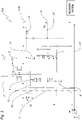
- the example in figure 4 illustrates, for example, the hydraulic circuit 100 in the case where the supply unit 101 is intended to supply two hydraulic utilities U1, U2. It should be noted that there may also be a larger number of utilities, as indicated above.
- hydraulic utility U1 can for example be represented by the operation of a double-acting hydraulic actuator or any other hydraulic apparatus. It will be appreciated that the same inventive concepts set out in connection with the present invention are also applicable to other solutions, such as a hydraulic motor. For this reason, the term "hydraulic utility" is used below to refer to any hydraulic apparatus intended to be operated via a hydraulic circuit with one or more working sections.
- the hydraulic circuit 100 comprises a distribution module 102 that receives a flow rate of operating fluid from the supply unit 101 to distribute the fluid towards the hydraulic utility U1.
- a distribution module 102 that receives a flow rate of operating fluid from the supply unit 101 to distribute the fluid towards the hydraulic utility U1.
- the distribution module comprises a spool 1 for operating the hydraulic utility.
- a spool 1 for operating the hydraulic utility.
- the spool 1 defines a main delivery channel 11, which receives a flow of fluid from the supply unit 101, and a discharge channel 13 through which the fluid exiting the hydraulic utility U1, for example from the hydraulic actuator illustrated in the example embodiment of the figures, transits.
- the spool comprises a delivery notch 14 through which the flow of fluid supplied by the supply unit 101 transits.
- the circuit comprises a secondary delivery branch 12, to which the main delivery branch 11 is connected.
- a check valve 15 is preferably located between the secondary pressure branch 12 and the main pressure branch 11.
- the delivery notch 14 is therefore advantageously configured such that the operating fluid transiting between the main delivery branch 11 and the secondary delivery branch 12 passes through the notch 14.
- the hydraulic circuit 100 of the present invention further comprises one or more three-way compensated adjustment devices 2, preferably in a number equal to the working sections of the circuit, and whose features will be explained in detail below.
- the compensated three-way adjustment device 2 is connected, at a first channel thereof 21, to the discharge branch 13 of the spool 1 and connected to discharge T at a second channel 22.
- a third channel 23 of the three-way compensated adjustment device 2 is connected to an energy recovery device 103, the latter being illustrated in more detail below.
- the adjustment device 2 can be adjusted, preferably by continuous adjustment, between three adjustment positions implemented via specific piloting signals. It will be understood that the term continuous adjustment means the ability to move gradually and continuously between positions. In other words, the opening and closing of a window of the adjustment device 2 takes place in a gradual manner, passing progressively from the closed to the open condition.
- the piloting signals are provided by a respective first piloting channel 31 through which a Maximum Load Sensing signal P LSmax acts on a first side 2A of the adjustment device 2, and by a second piloting channel 32 through which a Local Load Sensing signal P LSIoc acts on a second side 2B. It will be appreciated that the areas defined by sides 2A and 2B respectively are preferably equal.
- an additional force may also act, preferably defined by the action of a spring, or an equivalent elastic element 33.
- additional force can be provided alternatively or additionally by means of hydraulic piloting acting on one of the sides of the adjustment device.
- a connecting channel 24 may be provided which sends the signal taken from the second piloting channel 32 to the first piloting channel 31, passing through a relative notch 25 and a non-return valve 25A.
- the pressure of the maximum Load Sensing signal P LSmax is advantageously characteristic of the pressure of the higher pressure hydraulic utility if more than one section is present. Obviously, if there is only one utility U1, the pressure of the maximum Load Sensing signal P LSmax can correspond to that of such utility.
- the pressure of the local Load Sensing signal P LSIoc is taken from a section 11' through which the working fluid is supplied from the supply unit 101 to the hydraulic utility U1.
- the second piloting channel 32 is for this purpose connected to the section 11' of the main delivery branch 11 downstream of the spool 1 from which the Local Load Sensing signal P LSIoc is supplied.
- the Load Sensing signals from the various sections can be selected by selector valves, not shown in the diagram, so that the highest is taken to the supply unit, which in turn generates a supply pressure of a value equal to the Maximum Load Sensing plus a preset margin.
- the signals can be selected by the compensated adjustment controller 2.
- the circuit may also include an optional valve device 17 which allows the pressure value on one or both of the two channels A, B of the actuator of the hydraulic utility U1 to be limited according to the movement of the actuator and any load present.
- a pressure limiting valve 16 located on the signal line LS MAX allows the maximum pressure value of the system to be defined.
- the adjustment device 2 is kept normally open and, in a first position, is configured so that the first channel 10 is in connection with the energy recovery device 103 and a discharge line T. In this condition, the flow is therefore preferentially sent to the discharge T.
- the adjustment device starts moving towards a second position.
- the connection to the recovery device 103 is maintained via the third channel 23.
- the connection to the discharge T is instead throttled in this second position. In this way, the hydraulic flow is sent as a priority to the energy recovery device 103.
- the drawer In the third position, the drawer completely closes all passages or throttles them to the point of ensuring the necessary pressure for all operating conditions, preventing the flow from being directed to the discharge or to the energy recovery device 103.
- the fluid flow to the discharge channel 22 and to the energy recovery device 103 can be prevented or the fluid flow to the second channel 23 can be sent by means of a choked passage so as to guarantee the necessary pressure for all the operating conditions.
- the device 2 is configured to move gradually between positions, closing the channels, or throttling them, in a progressive manner.
- the flow rate outlet from the energy recovery line may be redirected, possibly through a check valve to the energy recovery device(s) 103 in order to store potential hydraulic energy to be used again in new active working steps.
- the adjustment device 2 may be configured so as to intervene if the utility activated by the spool is subjected to an inertial load F that acts in the same direction as the displacement of the actuator.
- the present invention provides for a selection section 104 by means of which a reduced pressure signal P rid is introduced into the circuit to be sent to the first piloting line 31 under predetermined conditions.
- these conditions are determined by lowering the pressure of the maximum load sensing signal P LSmax below a predetermined pressure value, which may correspond to the reduced pressure value P rid .
- the reduced pressure P rid normally has a lower value than the working pressure P and, in some embodiments, can have a value comprised between 15 and 20 bar. Obviously, different values may also be envisaged depending on the specific type of application.
- the adjustment device 2 moves between its positions according to the difference between the Maximum Load Sensing P LSmax and Local Load Sensing P LSIoc signals, i.e. the signals present on sides 2A and 2B of the device 2, respectively.
- the possibility of providing the reduced pressure signal Prid makes it possible to prevent the pressure on the side 2B of the Maximum Load Sensing signal P LSmax from falling below a predetermined value, defined by the reduced pressure. This allows the adjustment device 2 to be properly controlled, even under load conditions, for example, where there is low pressure and a high flow rate in the section.
- the adjustment device 2 may be configured in such a way that the flow is sent in a priority manner, via the channel 23, to the energy recovery device 103, at least as far as this is able to accept operating fluid.
- the adjustment device 2 Based on the difference between the Maximum Load Sensing signal P LSmax and the Local Load Sensing signal P LSIoc , the adjustment device 2 changes its position in such a way that it performs an adjustment action, i.e. it directs the operating fluid flow in such a way that a balanced situation is restored.
- the recovery device 2 tends to close the passage of operating fluid to the discharge and to throttle or close the passage towards the recovery device 103.
- the adjustment device 2 tends to open both the passage to discharge and the passage towards the recovery device, id the fluid will be sent in priority to discharge.
- the adjustment device 2 gradually moves to a position such that the fluid is sent to the recovery device 103, at least as long as the operating conditions of the latter permit it.
- the reduced pressure signal tends to be copied onto the local load sensing signal P LSIoc to restore a balanced situation.
- the reduced pressure signal Prid is supplied to the Maximum Load Sensing P LSmax line via a corresponding channel 41.
- a check valve 42 located along the channel 41 may be provided.
- the sending of the reduced pressure to the first piloting line 31 is adjusted by means of a two-way valve 3.
- the non-return valve 42 can in this case be interposed between the two-way valve 3 and the Maximum Load Sensing signal P LSmax line.
- the two-way valve 3 may be controlled electrically, hydraulically or mechanically in the presence of a dragging load F acting on the actuator of the hydraulic utility U1 in such a way that it switches to a position in which the reduced pressure fluid Prid is sent towards the first piloting line 31.
- the valve 3 can be activated whenever the spool 1 is piloted to perform a movement with a dragging load, such as lowering an excavator arm.
- the two-way valve can be activated by a mechanical device or hydraulic pilot control.
- control unit 7 which is responsible for adjusting the activation of the valve 3 according to the position of the spool 1.
- valve can be replaced by different selection devices 3 designed to send the flow at reduced pressure under predetermined conditions.
- the spool 1 includes an additional way 4' connected via a respective line to the reduced pressure Prid.
- the spool 1 is therefore configured to close this additional way 4' or connect it to a drainage outlet D depending on its operating position, in a manner conceptually similar to that described in relation to the embodiment of figure 1 .
- the selection section 104 comprises a pressure reducing valve 4 configured to reduce the working pressure P to the reduced pressure Prid.
- the pressure reducing valve 4 is connected to a delivery line 101A of the supply unit 101.
- the pressure reducing valve 4 is set in such a way that the outlet pressure is the reduced pressure Prid intended for the system, i.e. in the example described above a pressure comprised between 15 and 20 bar.
- the reduced pressure Prid can also be used to activate the spool 1.
- a control line 61 may be provided through which the reduced pressure Prid is supplied to the electro-hydraulic controls 6 for operating the spool 1.
- control line 61 is therefore advantageously connected to the valve 4.
- the energy recovery device 103 may comprise at least one accumulator that allows the hydraulic fluid to be stored in the cases in which the working conditions of the circuit allow it. It should be noted, however, that energy recovery within the scope of the present invention does not necessarily involve an accumulator.
- the energy recovery device 103 may be configured so as to reintroduce potential hydraulic energy back into the distribution module 102 that feeds the working sections, in other words, thus providing the feeding line of the hydraulic module with hydraulic fluid, for example collected in the accumulator.
- the energy recovery device 103 may be configured so as to transfer said hydraulic fluid to a system or device for transforming potential hydraulic energy provided by said hydraulic fluid into another form of energy.
- the device for transforming potential hydraulic energy may be depicted by an alternator, generator or a flywheel.
- the selection section 104 is configured to receive said reduced pressure Prid from an external source 8 of low pressure auxiliary operating fluid.
- the embodiment illustrated in figure 3 may also provide for reduced pressure to be supplied by the external source 8.
- the reduced pressure Prid is also used in the additional way 4' of the spool 1 and, for this purpose, a narrowing 81 may also be provided in the selection section 104 along the line connected to the external source 8. It will be appreciated that the narrowing 81 prevents excessive fluid flow in the piloting channel, thus preventing saturation of the circuit.
- circuit of the present invention enables the functions of compensation and energy recovery to be carried out effectively, even in the case of inertial loads acting in the same direction as the movement and such as to generate higher speeds than those generated by the flow rate at the outlet.
Abstract
Description
- The invention falls within the field of hydraulic distributors intended for managing hydraulic actuators by using pressure compensation devices.
- A known problem in off-highway applications, such as the ones of excavators, is the one of energy loss due to the work of compensators. An excessive choking of the in/out meter area due to the intervention of the local compensators results in an energy dissipation that is discharged through the fluid in the form of heat. For this reason, it is advantageous to reuse the energy which otherwise would be dissipated through the local compensator by channelling - if the compensator itself allows it - the primary flow into a bypass branch, which, according to the type of movement, redirects the fluid being fed by making the regenerative connection and/or recharges an accumulator or other energy recovery devices.
- An example of a hydraulic circuit comprising an energy recovery accumulator used in a hydraulic lifting system is proposed in patent application
DE 39 30 553 . - Such document describes a hydraulic circuit comprising a compensator arranged on the drain branch of a control valve for a single-effect actuation intended for lifting a load.
- An outlet branch from the compensator is connected to the accumulator, to which a flow of fluid is sent under certain operating conditions.
- However, known solutions are not efficient enough to operate in all the different working conditions and are not always suitable for use in modern off-highway applications.
- The technical problem at the basis of the present invention is to make available a hydraulic circuit that is structurally and functionally conceived to overcome, at least in part, one or more of the limitations disclosed above with reference to the mentioned known technique.
- Within the scope of such technical problem, the object of the present invention is to make available to the known art a hydraulic circuit provided with a three-way compensator capable of combining, with the usual flow adjustment functions that are typical of compensators, the ability to manage a primary flow with the aim of saving energy within the realm of a simple, rational and affordable solution.
- A further object is to make available a hydraulic circuit that allows the energy that normally is dissipated in the case of dragging loads or more generally, of inertial loads acting in the same direction as the movement, to be at least partially recovered.
- Yet another aim of the invention is to provide a hydraulic circuit that is suitable for use in excavators and, in general, in modern off-highway applications.
- These and other purposes are achieved by one or more of the features of the invention set out in the independent claim 1. The dependent claims outline preferred and/or particularly advantageous aspects of the invention.
- It will be observed that the hydraulic circuit of the present invention comprises a hydraulic distribution module with one or more working sections, and at least one compensated adjustment device, capable of managing a priority flow aimed at energy saving logic.
- The distribution module includes at least one spool intended to operate at least one hydraulic utility such as a hydraulic actuator.
- According to an aspect of the invention, the circuit comprises a supply unit, preferably with variable flow rate or pressure, configured to supply a flow of operating fluid at a working pressure to the spool delivery channel, for activating the hydraulic utility.
- In some embodiments, the compensated adjustment device is connected at its first channel to the spool discharge branch and connected to discharge at a second channel.
- Preferably, the compensated adjustment device is piloted on one side by the local load sensing signal and on the other side by the maximum load sensing signal.
- If there is more than one section, the maximum load sensing signal corresponds to that of the highest pressure working section.
- Another aspect is that the compensated adjustment device is connected to the energy recovery device which is responsible for implementing energy-saving logics, for example based on a regeneration system.
- It will be appreciated that the circuit of the present invention is also configured to receive a reduced pressure signal, which enables the compensated adjustment device to be activated in the case of driving and inertial loads acting in the same direction as the movement. The reduced pressure signal preferably has a lower value than the working pressure and acts on the compensated adjustment device of the maximum load sensing signal. In some embodiments, the reduced pressure value can be comprised between 15 and 20 bar, for example.
- Based on such pilot control, the compensated adjustment device is switched to direct the discharge flow from the spool towards the energy recovery device.
- It will therefore be appreciated that in this way, even in the case of dragging loads, a case in which the hydraulic actuator would supply a high flow rate of fluid in discharge, requiring a low pressure value in delivery, it is possible to activate the compensated adjustment device in order to implement the energy recovery logic that the circuit of the present invention provides.
- In some embodiments, the reduced pressure signal can be generated from the working pressure by means of a pressure reducing valve. Preferably the pressure reducing valve can be connected to a delivery line coming from the supply unit.
- According to another aspect, the reduced pressure signal can be provided by an external source of low-pressure auxiliary operating fluid.
- Therefore, it will be appreciated that the reduced pressure signal adopted in the circuit of the present invention can be easily obtained either by using the same flow rate of operating fluid already intended to activate the different sections, or by a simple connection to an external low pressure source.
- It will be appreciated that in the context of the present invention the term "low pressure" means a pressure significantly lower than that required for the operation of the hydraulic utilities envisaged by the application, for example a value comprised between 15 and 20 bar, as specified above. However, it is clear that this value will be linked to the effective application of the hydraulic circuit.
- According to another advantageous aspect of the invention, the passage of the reduced pressure towards the relevant piloting line of the compensated adjustment device is adjusted by means of a selection device which may comprise a two-way valve.
- In this way it is possible to achieve pilot control even in situations of dragging loads or other specific situations, in a simple and easily controllable manner.
- In some designs, the two-way valve, or other selection device used, is electrically controlled.
- It can also be envisaged that the spool will discharge the reduced pressure under specific conditions. For this purpose, the spool may include an additional way connected via a respective line to the reduced pressure. Preferably, the spool is configured to close this additional way or connect it to a drain depending on its operational position.
- Advantageously, the spool can be activated via electro-hydraulic controls. It will be appreciated, however, that different activations can also be provided, e.g. mechanical, hydraulic and electromechanical.
- In yet another aspect, the hydraulic circuit comprises a choke arranged in a shunt from the first piloting line towards the discharge.
- The presence of the choke prevents the accumulation of pressure on the maximum LS signal line and ensures rapid depressurisation of the system.
- According to another aspect of the invention, the two-way valve, or other selection device used, can be operated electrically, hydraulically or mechanically. For this purpose, there may be a control unit which, in the presence of a dragging load acting on the actuator of the working section, sends an electrical, hydraulic or mechanical command to switch the valve.
- Said objects and advantages are all achieved by the hydraulic circuit, the object of the present invention, which is characterised by the provisions of the claims below.
- This and other characteristics will be more apparent from the following description of certain embodiments illustrated by way of mere non-limiting example in the accompanying drawings, in which:
-
Figure 1 is a schematic drawing of a hydraulic circuit with a compensation and energy recovery function according to the present invention; -
Figure 2 is a schematic drawing of a hydraulic circuit with a compensation and energy recovery function according to one embodiment of the present invention; -
Figure 3 is a schematic drawing of a hydraulic circuit with a compensation and energy recovery function according to a further embodiment of the present invention; and -
Figure 4 is a schematic drawing of a hydraulic circuit with a compensation and energy recovery function according to the present invention, illustrating the configuration of the circuit when there are two working sections. - With initial reference to
Figure 1 , a hydraulic circuit according to the present invention is shown as a whole withnumeral 100. - As is noted below, the
hydraulic circuit 100 of the present invention has the function of compensation and energy recovery. - The
hydraulic circuit 100 is preferably supplied by means of asupply unit 101. Thesupply unit 101 may be of the variable flow or pressure type, as in the example embodiment shown in the figure. However, other solutions may be provided for the adjustment of thepower unit 101. - In some embodiments, the
supply unit 101 may comprise a variable displacement pump which adjusts the flow rate based on the pressure of the highest pressure utility among those supplied by the supply unit. The example infigure 4 illustrates, for example, thehydraulic circuit 100 in the case where thesupply unit 101 is intended to supply two hydraulic utilities U1, U2. It should be noted that there may also be a larger number of utilities, as indicated above. - However, the invention will be illustrated below in the case of a single hydraulic utility U1, as in the example of
Figure 1 . The hydraulic utility U1 can for example be represented by the operation of a double-acting hydraulic actuator or any other hydraulic apparatus. It will be appreciated that the same inventive concepts set out in connection with the present invention are also applicable to other solutions, such as a hydraulic motor. For this reason, the term "hydraulic utility" is used below to refer to any hydraulic apparatus intended to be operated via a hydraulic circuit with one or more working sections. - The
hydraulic circuit 100 comprises adistribution module 102 that receives a flow rate of operating fluid from thesupply unit 101 to distribute the fluid towards the hydraulic utility U1. As mentioned above, it should be noted that although there is only one utility in the illustrative embodiment shown infigure 1 , the present invention may also be applied in the case of a generic number of users n and corresponding work sections. - The distribution module comprises a spool 1 for operating the hydraulic utility. In the case of several sections intended to supply several utilities, it is preferable to have a corresponding number of spools, as in the example shown in
figure 4 where there are two sections and two corresponding spools 1. - The spool 1 defines a
main delivery channel 11, which receives a flow of fluid from thesupply unit 101, and adischarge channel 13 through which the fluid exiting the hydraulic utility U1, for example from the hydraulic actuator illustrated in the example embodiment of the figures, transits. - Preferably, the spool comprises a
delivery notch 14 through which the flow of fluid supplied by thesupply unit 101 transits. - In some embodiments, the circuit comprises a
secondary delivery branch 12, to which themain delivery branch 11 is connected. Acheck valve 15 is preferably located between thesecondary pressure branch 12 and themain pressure branch 11. Thedelivery notch 14 is therefore advantageously configured such that the operating fluid transiting between themain delivery branch 11 and thesecondary delivery branch 12 passes through thenotch 14. - The
hydraulic circuit 100 of the present invention further comprises one or more three-way compensatedadjustment devices 2, preferably in a number equal to the working sections of the circuit, and whose features will be explained in detail below. - As can best be appreciated from the example illustrated in
figure 1 , the compensated three-way adjustment device 2 is connected, at afirst channel thereof 21, to thedischarge branch 13 of the spool 1 and connected to discharge T at asecond channel 22. - A
third channel 23 of the three-way compensatedadjustment device 2 is connected to anenergy recovery device 103, the latter being illustrated in more detail below. - The
adjustment device 2 can be adjusted, preferably by continuous adjustment, between three adjustment positions implemented via specific piloting signals. It will be understood that the term continuous adjustment means the ability to move gradually and continuously between positions. In other words, the opening and closing of a window of theadjustment device 2 takes place in a gradual manner, passing progressively from the closed to the open condition. - According to a preferred embodiment, the piloting signals are provided by a respective first piloting
channel 31 through which a Maximum Load Sensing signal PLSmax acts on afirst side 2A of theadjustment device 2, and by a second pilotingchannel 32 through which a Local Load Sensing signal PLSIoc acts on asecond side 2B. It will be appreciated that the areas defined bysides - In some embodiments, on the
second side 2B, in addition to the pressure provided by the local Load Sensing signal PLSIoc, an additional force may also act, preferably defined by the action of a spring, or an equivalentelastic element 33. However, it will be appreciated that additional force can be provided alternatively or additionally by means of hydraulic piloting acting on one of the sides of the adjustment device. - According to a further aspect, a connecting
channel 24 may be provided which sends the signal taken from the second pilotingchannel 32 to the first pilotingchannel 31, passing through arelative notch 25 and anon-return valve 25A. - It will be appreciated that the pressure of the maximum Load Sensing signal PLSmax is advantageously characteristic of the pressure of the higher pressure hydraulic utility if more than one section is present. Obviously, if there is only one utility U1, the pressure of the maximum Load Sensing signal PLSmax can correspond to that of such utility.
- According to a further aspect, the pressure of the local Load Sensing signal PLSIoc is taken from a
section 11' through which the working fluid is supplied from thesupply unit 101 to the hydraulic utility U1. Preferably, the second pilotingchannel 32 is for this purpose connected to thesection 11' of themain delivery branch 11 downstream of the spool 1 from which the Local Load Sensing signal PLSIoc is supplied. - It will also be appreciated that, according to a preferred embodiment, where there is more than one working section, the Load Sensing signals from the various sections can be selected by selector valves, not shown in the diagram, so that the highest is taken to the supply unit, which in turn generates a supply pressure of a value equal to the Maximum Load Sensing plus a preset margin. Alternatively, the signals can be selected by the compensated
adjustment controller 2. - The circuit may also include an
optional valve device 17 which allows the pressure value on one or both of the two channels A, B of the actuator of the hydraulic utility U1 to be limited according to the movement of the actuator and any load present. - In preferred embodiments, a
pressure limiting valve 16 located on the signal line LSMAX allows the maximum pressure value of the system to be defined. - Preferably, the
adjustment device 2 is kept normally open and, in a first position, is configured so that the first channel 10 is in connection with theenergy recovery device 103 and a discharge line T. In this condition, the flow is therefore preferentially sent to the discharge T. - As the difference in pressure between the first piloting
channel 31 and the second pilotingchannel 32 increases, the adjustment device starts moving towards a second position. In this intermediate position, the connection to therecovery device 103 is maintained via thethird channel 23. In some embodiments, the connection to the discharge T is instead throttled in this second position. In this way, the hydraulic flow is sent as a priority to theenergy recovery device 103. - In the third position, the drawer completely closes all passages or throttles them to the point of ensuring the necessary pressure for all operating conditions, preventing the flow from being directed to the discharge or to the
energy recovery device 103. For this purpose, in the third position the fluid flow to thedischarge channel 22 and to theenergy recovery device 103 can be prevented or the fluid flow to thesecond channel 23 can be sent by means of a choked passage so as to guarantee the necessary pressure for all the operating conditions. - It will be appreciated that, as mentioned above, the
device 2 is configured to move gradually between positions, closing the channels, or throttling them, in a progressive manner. - Again with reference to
Figure 1 , in the movement of actuators in the presence of dragging loads, for example under return conditions of the actuator with the external force F in a concordant direction with the displacement of the actuator, the flow rate outlet from the energy recovery line may be redirected, possibly through a check valve to the energy recovery device(s) 103 in order to store potential hydraulic energy to be used again in new active working steps. - More generally, the
adjustment device 2 may be configured so as to intervene if the utility activated by the spool is subjected to an inertial load F that acts in the same direction as the displacement of the actuator. - In order to ensure correct operation under all inertial load conditions F, the present invention provides for a
selection section 104 by means of which a reduced pressure signal Prid is introduced into the circuit to be sent to the first pilotingline 31 under predetermined conditions. - Preferably, these conditions are determined by lowering the pressure of the maximum load sensing signal PLSmax below a predetermined pressure value, which may correspond to the reduced pressure value Prid.
- The reduced pressure Prid normally has a lower value than the working pressure P and, in some embodiments, can have a value comprised between 15 and 20 bar. Obviously, different values may also be envisaged depending on the specific type of application.
- As can be seen from the figures, the
adjustment device 2 moves between its positions according to the difference between the Maximum Load Sensing PLSmax and Local Load Sensing PLSIoc signals, i.e. the signals present onsides device 2, respectively. - The possibility of providing the reduced pressure signal Prid makes it possible to prevent the pressure on the
side 2B of the Maximum Load Sensing signal PLSmax from falling below a predetermined value, defined by the reduced pressure. This allows theadjustment device 2 to be properly controlled, even under load conditions, for example, where there is low pressure and a high flow rate in the section. - In general, the
adjustment device 2 may be configured in such a way that the flow is sent in a priority manner, via thechannel 23, to theenergy recovery device 103, at least as far as this is able to accept operating fluid. - Based on the difference between the Maximum Load Sensing signal PLSmax and the Local Load Sensing signal PLSIoc, the
adjustment device 2 changes its position in such a way that it performs an adjustment action, i.e. it directs the operating fluid flow in such a way that a balanced situation is restored. - If the pressure of the Maximum Load Sensing signal PLSmax is greater than that of the Local Load Sensing signal PLSIoc, possibly net of the action of the
spring 33, then therecovery device 2 tends to close the passage of operating fluid to the discharge and to throttle or close the passage towards therecovery device 103. - Vice versa, if the pressure of the Local Load Sensing signal PLSIoc is greater than that of the Maximum Load Sensing signal PLSmax, then the
adjustment device 2 tends to open both the passage to discharge and the passage towards the recovery device, id the fluid will be sent in priority to discharge. - These situations tend to bring the Maximum Load Sensing PLSmax and Local Load Sensing PLSIoc signals back into balance, thus achieving the adjustment function by the
device 2. - When the reduced-pressure signal Prid is sent to the first piloting
line 31, an unbalanced situation may then occur in theadjustment device 2. In other words, according to the above, when theadjustment device 2 feels the pressure Prid, it will tend to move to try to replicate the pressures, returning to a balanced condition. - For example, under dragging load conditions it may occur that, after the reduced pressure signal Prid has been sent, it moves towards the position where the fluid is sent to the
recovery device 103. If, therefore, initially the pressure of the Load Sensing Local signal PLSIoc prevails over the reduced pressure Prid and the fluid is sent predominantly to discharge, theadjustment device 2 gradually moves to a position such that the fluid is sent to therecovery device 103, at least as long as the operating conditions of the latter permit it. In fact, the reduced pressure signal tends to be copied onto the local load sensing signal PLSIoc to restore a balanced situation. - In other words, by providing for the presence of the reduced pressure signal Prid in specific load conditions, such as in the case of a dragging load, it is therefore possible to activate the compensated three-
way adjustment device 2 in switching towards the second position, i.e. in the position in which the fluid coming from thedischarge branch 21 is sent to theenergy recovery device 103. - It will be appreciated that according to yet another aspect, there is a
choke 5 arranged in derivation from the first pilotingline 31 towards discharge. Thanks to the presence of thechoke 5, it is possible to depressurise the circuit quickly when therecovery device 2 returns to the central position. - Preferably, the reduced pressure signal Prid is supplied to the Maximum Load Sensing PLSmax line via a corresponding
channel 41. In order to prevent the Maximum Load Sensing signal PLSmax from being sent towards the reducedpressure section 104, acheck valve 42 located along thechannel 41 may be provided. - In some embodiments the sending of the reduced pressure to the first piloting
line 31 is adjusted by means of a two-way valve 3. Thenon-return valve 42 can in this case be interposed between the two-way valve 3 and the Maximum Load Sensing signal PLSmax line. - The two-
way valve 3 may be controlled electrically, hydraulically or mechanically in the presence of a dragging load F acting on the actuator of the hydraulic utility U1 in such a way that it switches to a position in which the reduced pressure fluid Prid is sent towards the first pilotingline 31. - The
valve 3 can be activated whenever the spool 1 is piloted to perform a movement with a dragging load, such as lowering an excavator arm. - Alternatively, the two-way valve can be activated by a mechanical device or hydraulic pilot control.
- Therefore, in general, there may be a
control unit 7 which is responsible for adjusting the activation of thevalve 3 according to the position of the spool 1. - It will also be appreciated that the valve can be replaced by
different selection devices 3 designed to send the flow at reduced pressure under predetermined conditions. - For example, in some embodiments, such as the one shown in
figure 3 , it may be provided that the spool 1 includes anadditional way 4' connected via a respective line to the reduced pressure Prid. - The spool 1 is therefore configured to close this
additional way 4' or connect it to a drainage outlet D depending on its operating position, in a manner conceptually similar to that described in relation to the embodiment offigure 1 . - Referring again to
figure 1 , in some embodiments, theselection section 104 comprises apressure reducing valve 4 configured to reduce the working pressure P to the reduced pressure Prid. Preferably, thepressure reducing valve 4 is connected to adelivery line 101A of thesupply unit 101. - The
pressure reducing valve 4 is set in such a way that the outlet pressure is the reduced pressure Prid intended for the system, i.e. in the example described above a pressure comprised between 15 and 20 bar. - It will also be appreciated that in some embodiments, as can be seen from
figure 1 , the reduced pressure Prid can also be used to activate the spool 1. - This is particularly advantageous when spool 1 is activated by electro-
hydraulic controls 6. - In such a case, a
control line 61 may be provided through which the reduced pressure Prid is supplied to the electro-hydraulic controls 6 for operating the spool 1. - If there is a
pressure reducing valve 4, thecontrol line 61 is therefore advantageously connected to thevalve 4. - In order to obtain the energy recovery action required, based on one aspect of the invention, the
energy recovery device 103 may comprise at least one accumulator that allows the hydraulic fluid to be stored in the cases in which the working conditions of the circuit allow it. It should be noted, however, that energy recovery within the scope of the present invention does not necessarily involve an accumulator. - According to a further aspect of the invention, the
energy recovery device 103 may be configured so as to reintroduce potential hydraulic energy back into thedistribution module 102 that feeds the working sections, in other words, thus providing the feeding line of the hydraulic module with hydraulic fluid, for example collected in the accumulator. - Based again on another aspect, the
energy recovery device 103 may be configured so as to transfer said hydraulic fluid to a system or device for transforming potential hydraulic energy provided by said hydraulic fluid into another form of energy. For example, the device for transforming potential hydraulic energy may be depicted by an alternator, generator or a flywheel. - It in any case is understood that also other solutions suitable for energy recovery may be provided within the realm of the circuit of the present invention, and the above examples are to be intended as given merely by way of non-limiting example.
- Referring now to the example in
figure 2 , an alternative embodiment of the present invention will be described, whereby anexternal source 8 is used to supply the reduced pressure Prid. - For this purpose, the
selection section 104 is configured to receive said reduced pressure Prid from anexternal source 8 of low pressure auxiliary operating fluid. - The embodiment illustrated in
figure 3 may also provide for reduced pressure to be supplied by theexternal source 8. In this case, as previously described, the reduced pressure Prid is also used in theadditional way 4' of the spool 1 and, for this purpose, a narrowing 81 may also be provided in theselection section 104 along the line connected to theexternal source 8. It will be appreciated that the narrowing 81 prevents excessive fluid flow in the piloting channel, thus preventing saturation of the circuit. - In any case, these solutions can also be combined with all the embodiments described above.
- It will therefore be appreciated that the circuit of the present invention enables the functions of compensation and energy recovery to be carried out effectively, even in the case of inertial loads acting in the same direction as the movement and such as to generate higher speeds than those generated by the flow rate at the outlet.
Claims (15)
- A hydraulic circuit (100) having a compensation and energy recovery function, comprising:• a distribution module (102) for distributing hydraulic fluid which includes at least one spool (1) for actuating at least one hydraulic utility (U1), for example a hydraulic actuator, wherein:
∘ the spool (1) is configured to define a main delivery branch (11), and a discharge branch (13) in the distribution module (102),• a supply unit configured so as to supply a flow rate of operating fluid at a working pressure (P) to the main delivery branch (11), for activating the hydraulic utility (U1);• a three-way compensated adjustment device (2) connected, at a first channel (21) thereof, to the discharge branch (13) of the spool (1) and connected to discharge (T) at a second channel (22);
∘ the three-way compensated adjustment device (2) further comprises a first piloting line (31) and a second piloting line (32) configured so that through the first piloting line (31) a Maximum Load Sensing (PLSmax) piloting signal acts on a first side (2A) of the adjustment device (2), which signal is characteristic of the pressure of the hydraulic utility (U1) if there is a single section, or of the hydraulic utility at higher pressure if there is more than one hydraulic utility, and so that through the second piloting line (31) a Local Load Sensing (PLSIoc) piloting signal acts on a second side (2B) of the three-way compensated adjustment device (2), which signal is characteristic of a local pressure of the operating fluid supplied to said hydraulic utility (U1) by the supply unit (101), the hydraulic circuit further comprises:• an energy recovery device (103) connected to a third channel (23) of the three-way compensated adjustment device (2);• a selection section (104) configured in such a way as to receive a signal at reduced pressure (RedP) and send it to said first piloting line (31) in such a way as to activate said three-way compensated adjustment device (2) for switching towards a position in which the fluid coming from the discharge branch (21) is sent to said energy recovery device (103) connected through said third channel (23). - The hydraulic circuit (100) according to claim 1, wherein said selection section (104) comprises a pressure reducing valve (4) configured in such a way as to reduce said working pressure (P) to said reduced pressure (RedP) signal.
- The hydraulic circuit (100) according to claim 2, wherein said pressure reducing valve (4) is connected to a pressure line (101A) of the supply unit (10).
- The hydraulic circuit (100) according to claim 1 or 2, wherein said selection section comprises a selection device (3) configured to selectively allow and prevent the passage of said reduced pressure (RedP) signal to said first piloting line (31).
- The hydraulic circuit (100) according to claim 3, wherein the selection device (3) comprises a two-way valve.
- The hydraulic circuit (100) according to any one of the preceding claims, wherein said spool (1) comprises an additional way (4') connected through a respective line to said reduced pressure (RedP) signal, said spool (1) being configured to close said additional way (4') or to connect it to a drainage discharge (D) according to an operating position thereof.
- The hydraulic circuit (100) according to any one of the preceding claims, wherein said spool (1) is activated by electrohydraulic commands (6) and further comprising a command line (61) through which said reduced pressure (RedP) signal is supplied to said electrohydraulic commands (6) for actuating the spool (1).
- The hydraulic circuit (100) according to any one of the preceding claims, wherein said selection section (104) is configured to receive said reduced pressure (RedP) signal from an external source (8) of auxiliary operating fluid at low pressure.
- The hydraulic circuit (100) according to any one of the preceding claims, when dependent on claim 4, comprising a control unit (7) configured to activate said selection device (3) electrically, hydraulically or mechanically, preferably in the presence of a dragging load (F) which acts on said actuator of said hydraulic utility (U1).
- The hydraulic circuit (100) according to any one of the preceding claims, wherein said supply unit (101) is at variable flow rate or pressure.
- The hydraulic circuit (100) according to any one of the preceding claims, wherein said selection section (104) comprises a reduced pressure signal channel (41) connected to said first piloting line (31) and a check valve (42) placed along said reduced pressure signal channel (41) configured to prevent fluid of the Maximum Load Sensing signal (PLSmax) from being sent to said selection section (104) through said reduced pressure signal channel (41).
- The hydraulic circuit (100) according to any of the preceding claims, wherein the reduced pressure value is comprised between 15 and 20 bar.
- The hydraulic circuit (100) according to any one of the preceding claims, when dependent on claim 4, wherein said selection device (3) is electrically controlled.
- The hydraulic circuit (100) according to any one of the preceding claims, comprising three-way compensated adjustment devices (2) in a number equal to a number of working sections in the circuit.
- The hydraulic circuit (100) according to any one of the preceding claims, comprising an elastic element (33) configured to generate a force on said second side (2B), in addition to the pressure provided by the Local Load Sensing signal (PLSIoc).
Applications Claiming Priority (1)
| Application Number | Priority Date | Filing Date | Title |
|---|---|---|---|
| IT102020000027561A IT202000027561A1 (en) | 2020-11-17 | 2020-11-17 | HYDRAULIC CIRCUIT WITH COMBINED FUNCTION OF COMPENSATION AND ENERGY RECOVERY |
Publications (1)
| Publication Number | Publication Date |
|---|---|
| EP4001671A1 true EP4001671A1 (en) | 2022-05-25 |
Family
ID=74557051
Family Applications (1)
| Application Number | Title | Priority Date | Filing Date |
|---|---|---|---|
| EP21208732.4A Pending EP4001671A1 (en) | 2020-11-17 | 2021-11-17 | Hydraulic circuit with combined compensation and energy recovery function |
Country Status (3)
| Country | Link |
|---|---|
| US (1) | US20220154743A1 (en) |
| EP (1) | EP4001671A1 (en) |
| IT (1) | IT202000027561A1 (en) |
Families Citing this family (1)
| Publication number | Priority date | Publication date | Assignee | Title |
|---|---|---|---|---|
| CN115013561B (en) * | 2022-08-09 | 2022-11-11 | 宁波佳尔灵气动机械有限公司 | Electromagnetic valve with safety mode |
Citations (4)
| Publication number | Priority date | Publication date | Assignee | Title |
|---|---|---|---|---|
| DE3930553A1 (en) | 1989-09-13 | 1991-03-14 | Bosch Gmbh Robert | Lifting mechanism hydraulic control system - has pressure-equalisers for flow to and from pressure accumulator |
| WO2014121910A1 (en) * | 2013-02-05 | 2014-08-14 | Karlsruher Institut für Technologie | Hydraulic multi-load system with energy-efficient hydraulic circuit |
| DE102016117208A1 (en) * | 2016-09-13 | 2018-03-15 | Linde Hydraulics Gmbh & Co. Kg | Load-sensing drive system |
| IT201700042145A1 (en) * | 2017-04-14 | 2018-10-14 | Walvoil Spa | HYDRAULIC CIRCUIT WITH COMBINED COMPENSATION AND ENERGY RECOVERY FUNCTION |
-
2020
- 2020-11-17 IT IT102020000027561A patent/IT202000027561A1/en unknown
-
2021
- 2021-11-16 US US17/527,227 patent/US20220154743A1/en active Pending
- 2021-11-17 EP EP21208732.4A patent/EP4001671A1/en active Pending
Patent Citations (4)
| Publication number | Priority date | Publication date | Assignee | Title |
|---|---|---|---|---|
| DE3930553A1 (en) | 1989-09-13 | 1991-03-14 | Bosch Gmbh Robert | Lifting mechanism hydraulic control system - has pressure-equalisers for flow to and from pressure accumulator |
| WO2014121910A1 (en) * | 2013-02-05 | 2014-08-14 | Karlsruher Institut für Technologie | Hydraulic multi-load system with energy-efficient hydraulic circuit |
| DE102016117208A1 (en) * | 2016-09-13 | 2018-03-15 | Linde Hydraulics Gmbh & Co. Kg | Load-sensing drive system |
| IT201700042145A1 (en) * | 2017-04-14 | 2018-10-14 | Walvoil Spa | HYDRAULIC CIRCUIT WITH COMBINED COMPENSATION AND ENERGY RECOVERY FUNCTION |
Also Published As
| Publication number | Publication date |
|---|---|
| IT202000027561A1 (en) | 2022-05-17 |
| US20220154743A1 (en) | 2022-05-19 |
Similar Documents
| Publication | Publication Date | Title |
|---|---|---|
| US7513109B2 (en) | Hydraulic controller for working machine | |
| US7353744B2 (en) | Hydraulic control | |
| EP0331076A1 (en) | Hydraulic circuit for cylinder | |
| EP1764515B1 (en) | Hydraulic control system for heavy construction equipment | |
| JPH08209751A (en) | Hydraulic flow priority system | |
| WO2021039284A1 (en) | Hydraulic system for construction machine | |
| EP4001671A1 (en) | Hydraulic circuit with combined compensation and energy recovery function | |
| WO2021039285A1 (en) | Hydraulic system for construction machine | |
| JP7404258B2 (en) | fluid circuit | |
| US5493950A (en) | Variable priority device for swing motor in heavy construction equipment | |
| GB2271870A (en) | A hydrostatic drive system | |
| CN110094377B (en) | Working machine with hydraulic device for energy recovery | |
| JP2769799B2 (en) | Variable priority device | |
| KR100964113B1 (en) | Swing control system for construction heavy equipment | |
| JP3081968B2 (en) | Cutoff cancellation mechanism in load sensing system | |
| EP0704630B1 (en) | Variable priority device for heavy construction equipment | |
| JPH068641B2 (en) | Hydraulic circuit | |
| WO2022209967A1 (en) | Fluid circuit | |
| KR20200135275A (en) | Hydraulic circuit of the working vehicle | |
| EP3744984B1 (en) | Oleodynamic valve | |
| JP2003287002A (en) | Hydraulic circuit in working machinery | |
| JPH0551947A (en) | Actuator controller for construction machine | |
| JPH04140330A (en) | Hydraulic circuit of operation system in construction machine | |
| JP2504014Y2 (en) | Work machine hydraulic control circuit of construction machine | |
| JP2001355613A (en) | Hydraulic control device and construction machinery |
Legal Events
| Date | Code | Title | Description |
|---|---|---|---|
| PUAI | Public reference made under article 153(3) epc to a published international application that has entered the european phase |
Free format text: ORIGINAL CODE: 0009012 |
|
| STAA | Information on the status of an ep patent application or granted ep patent |
Free format text: STATUS: THE APPLICATION HAS BEEN PUBLISHED |
|
| AK | Designated contracting states |
Kind code of ref document: A1 Designated state(s): AL AT BE BG CH CY CZ DE DK EE ES FI FR GB GR HR HU IE IS IT LI LT LU LV MC MK MT NL NO PL PT RO RS SE SI SK SM TR |
|
| STAA | Information on the status of an ep patent application or granted ep patent |
Free format text: STATUS: REQUEST FOR EXAMINATION WAS MADE |
|
| 17P | Request for examination filed |
Effective date: 20221125 |
|
| RBV | Designated contracting states (corrected) |
Designated state(s): AL AT BE BG CH CY CZ DE DK EE ES FI FR GB GR HR HU IE IS IT LI LT LU LV MC MK MT NL NO PL PT RO RS SE SI SK SM TR |
|
| P01 | Opt-out of the competence of the unified patent court (upc) registered |
Effective date: 20230622 |