EP4001495A1 - Water recirculation assembly for a laundry appliance - Google Patents
Water recirculation assembly for a laundry appliance Download PDFInfo
- Publication number
- EP4001495A1 EP4001495A1 EP21207653.3A EP21207653A EP4001495A1 EP 4001495 A1 EP4001495 A1 EP 4001495A1 EP 21207653 A EP21207653 A EP 21207653A EP 4001495 A1 EP4001495 A1 EP 4001495A1
- Authority
- EP
- European Patent Office
- Prior art keywords
- tube
- tub
- drum
- laundry appliance
- door
- Prior art date
- Legal status (The legal status is an assumption and is not a legal conclusion. Google has not performed a legal analysis and makes no representation as to the accuracy of the status listed.)
- Granted
Links
Images




Classifications
-
- D—TEXTILES; PAPER
- D06—TREATMENT OF TEXTILES OR THE LIKE; LAUNDERING; FLEXIBLE MATERIALS NOT OTHERWISE PROVIDED FOR
- D06F—LAUNDERING, DRYING, IRONING, PRESSING OR FOLDING TEXTILE ARTICLES
- D06F39/00—Details of washing machines not specific to a single type of machines covered by groups D06F9/00 - D06F27/00
- D06F39/08—Liquid supply or discharge arrangements
- D06F39/083—Liquid discharge or recirculation arrangements
-
- D—TEXTILES; PAPER
- D06—TREATMENT OF TEXTILES OR THE LIKE; LAUNDERING; FLEXIBLE MATERIALS NOT OTHERWISE PROVIDED FOR
- D06F—LAUNDERING, DRYING, IRONING, PRESSING OR FOLDING TEXTILE ARTICLES
- D06F37/00—Details specific to washing machines covered by groups D06F21/00 - D06F25/00
- D06F37/26—Casings; Tubs
- D06F37/267—Tubs specially adapted for mounting thereto components or devices not provided for in preceding subgroups
-
- D—TEXTILES; PAPER
- D06—TREATMENT OF TEXTILES OR THE LIKE; LAUNDERING; FLEXIBLE MATERIALS NOT OTHERWISE PROVIDED FOR
- D06F—LAUNDERING, DRYING, IRONING, PRESSING OR FOLDING TEXTILE ARTICLES
- D06F39/00—Details of washing machines not specific to a single type of machines covered by groups D06F9/00 - D06F27/00
- D06F39/08—Liquid supply or discharge arrangements
- D06F39/088—Liquid supply arrangements
-
- D—TEXTILES; PAPER
- D06—TREATMENT OF TEXTILES OR THE LIKE; LAUNDERING; FLEXIBLE MATERIALS NOT OTHERWISE PROVIDED FOR
- D06F—LAUNDERING, DRYING, IRONING, PRESSING OR FOLDING TEXTILE ARTICLES
- D06F39/00—Details of washing machines not specific to a single type of machines covered by groups D06F9/00 - D06F27/00
- D06F39/12—Casings; Tubs
-
- D—TEXTILES; PAPER
- D06—TREATMENT OF TEXTILES OR THE LIKE; LAUNDERING; FLEXIBLE MATERIALS NOT OTHERWISE PROVIDED FOR
- D06F—LAUNDERING, DRYING, IRONING, PRESSING OR FOLDING TEXTILE ARTICLES
- D06F39/00—Details of washing machines not specific to a single type of machines covered by groups D06F9/00 - D06F27/00
- D06F39/12—Casings; Tubs
- D06F39/14—Doors or covers; Securing means therefor
-
- D—TEXTILES; PAPER
- D06—TREATMENT OF TEXTILES OR THE LIKE; LAUNDERING; FLEXIBLE MATERIALS NOT OTHERWISE PROVIDED FOR
- D06F—LAUNDERING, DRYING, IRONING, PRESSING OR FOLDING TEXTILE ARTICLES
- D06F21/00—Washing machines with receptacles, e.g. perforated, having a rotary movement, e.g. oscillatory movement
- D06F21/02—Washing machines with receptacles, e.g. perforated, having a rotary movement, e.g. oscillatory movement about a horizontal axis
- D06F21/04—Washing machines with receptacles, e.g. perforated, having a rotary movement, e.g. oscillatory movement about a horizontal axis within an enclosing receptacle
-
- D—TEXTILES; PAPER
- D06—TREATMENT OF TEXTILES OR THE LIKE; LAUNDERING; FLEXIBLE MATERIALS NOT OTHERWISE PROVIDED FOR
- D06F—LAUNDERING, DRYING, IRONING, PRESSING OR FOLDING TEXTILE ARTICLES
- D06F37/00—Details specific to washing machines covered by groups D06F21/00 - D06F25/00
- D06F37/26—Casings; Tubs
- D06F37/28—Doors; Security means therefor
-
- D—TEXTILES; PAPER
- D06—TREATMENT OF TEXTILES OR THE LIKE; LAUNDERING; FLEXIBLE MATERIALS NOT OTHERWISE PROVIDED FOR
- D06F—LAUNDERING, DRYING, IRONING, PRESSING OR FOLDING TEXTILE ARTICLES
- D06F39/00—Details of washing machines not specific to a single type of machines covered by groups D06F9/00 - D06F27/00
- D06F39/08—Liquid supply or discharge arrangements
- D06F39/083—Liquid discharge or recirculation arrangements
- D06F39/085—Arrangements or adaptations of pumps
Definitions
- the present disclosure generally relates to a laundry appliance, and more specifically, to a water recirculation assembly for a laundry appliance.
- a laundry appliance includes a cabinet that includes a pump and a door proximate to the cabinet.
- a tub is disposed within the cabinet and is proximate to the door and is operably coupled to the drum.
- a water recirculation assembly is operably coupled to the cabinet and the door and is disposed proximate to the tub.
- the water recirculation assembly includes a first tube that is attached to the cabinet and is operably coupled to the pump, a second tube that is operably coupled to the door, and a gap that is defined between the first tube and the second tube.
- a laundry appliance includes a cabinet that includes a pump.
- a drum is disposed within the cabinet and a tub is operably coupled to the drum.
- a water recirculation assembly is coupled to the tub.
- the water recirculation assembly includes an inlet tube, and a manifold tube is coupled to the inlet tube.
- the manifold tube defines a plurality of apertures along at least a portion of the manifold tube.
- a laundry appliance includes a cabinet that includes a pump.
- a drum is disposed within the cabinet and a tub is operably coupled to the drum and is disposed proximate to the cabinet.
- a water recirculation assembly is operably coupled to the pump.
- the water recirculation assembly includes a first tube that is operably coupled to the pump within the cabinet, a second tube that is fluidly coupled to the first tube, and a gap that is defined between the first tube and the second tube.
- the terms “upper,” “lower,” “right,” “left,” “rear,” “front,” “vertical,” “horizontal,” and derivatives thereof shall relate to the disclosure as oriented in FIG. 1 .
- the term “front” shall refer to the surface of the element closer to an intended viewer, and the term “rear” shall refer to the surface of the element further from the intended viewer.
- the disclosure may assume various alternative orientations, except where expressly specified to the contrary.
- the specific devices and processes illustrated in the attached drawings, and described in the following specification are simply exemplary embodiments of the inventive concepts defined in the appended claims. Hence, specific dimensions and other physical characteristics relating to the embodiments disclosed herein are not to be considered as limiting, unless the claims expressly state otherwise.
- reference numeral 10 generally designates a laundry appliance that includes a cabinet 12 with a pump 14.
- a door 16 is positioned proximate to the cabinet 12 and includes an outer frame 18 and a central portion 20.
- a drum 22 is positioned within the cabinet 12, and a tub 24 is proximate to the door 16 and operably coupled to the drum 22.
- a water recirculation assembly 26 can be operably coupled to the cabinet 12 and the door 16.
- the water recirculation assembly 26 is also disposed proximate to the tub 24.
- the water recirculation assembly 26 includes a first tube 28 that is operably coupled to the pump 14 and a second tube 30 can be operably coupled to the door 16.
- a gap 32 can be defined between the first tube 28 and the second tube 30.
- the cabinet 12 of the laundry appliance 10 includes an aesthetic door 38 coupled to a front panel 40 that surrounds the door 16 and includes a user interface 42.
- the aesthetic door 38 is coupled to the front panel 40 of the cabinet 12, and the door 16 is coupled to the tub 24 proximate to the front panel 40.
- the aesthetic door 38 and the door 16 are operable between opened and closed positions 44, 46.
- the aesthetic door 38 and the door 16 may be a flat panel door, a fishbowl style door, or a combination thereof.
- the door 16 is configured to provide access to the drum 22 positioned within the cabinet 12 when the door 16 is in the open position 44 and encloses the tub 24 and the drum 22 when the door 16 is in the closed position 46.
- the door 16 includes the central portion 20 and the outer frame 18 disposed around the central portion 20. It is generally contemplated that the central portion 20 can be transparent. However, it is also contemplated that the central portion 20 may be opaque and/or translucent.
- the cabinet 12 includes the pump 14, which is configured to collect a liquid 48 and ultimately circulate the liquid 48 to be disposed within the drum 22, described in more detail below.
- the pump 14 is generally housed within the cabinet 12 and is fluidly coupled to the water recirculation assembly 26.
- the pump 14 can be positioned within the cabinet 12 beneath the drum 22 and includes a hose 50.
- the hose 50 extends from the pump 14 and is routed toward the first tube 28.
- the liquid 48 described herein is generally contemplated to be water, but may also include a combination of water and detergent, recycled water, or other liquids and chemistries typically collected and circulated by the pump 14.
- the hose 50 dispenses the liquid 48 from the pump 14 to the first tube 28, described further below.
- a frame 52 is coupled to the tub 24 and generally surrounds the door 16 in the closed position 46 of the door 16.
- the frame 52 is disposed behind the front panel 40 to conceal the frame 52, and the door 16 may generally flush with the cabinet 12, such that the door 16 may be generally aligned with the front panel 40 and surrounded by the frame 52.
- the first tube 28 is operably coupled to the frame 52.
- the first tube 28 is generally fixed relative to the frame 52. Stated differently, the first tube 28 may be integrally formed with the frame 52 to the extent that the first tube 28 is disposed within the frame 52.
- the central portion 20 of the door 16 is generally spaced apart from the frame 52.
- the first tube 28 is disposed within the frame 52 and is spaced apart from the second tube 30 that is operably coupled to the door 16. This general separation of the frame 52 and the central portion 20 of the door 16 also defines the gap 32 between the first tube 28 and the second tube 30.
- the door 16 is operably coupled to the tub 24 proximate to the drum 22.
- the tub 24 and the drum 22 define an opening 54 through which articles, such as clothing, are disposed within the drum 22 to be processed.
- the door 16 provides selective access to the drum 22 via the opening 54.
- the door 16 is configured to cover the opening 54 in the closed position 46 of the door 16 and provide access to the opening 54 in the open position 44 of the door 16.
- the door 16 may be in fluid communication with the drum 22, such that the liquid 48 may enter the drum 22 proximate to the door 16 and through the opening 54.
- the first tube 28 of the water recirculation assembly 26 is disposed within the frame 52 of the cabinet 12, and the second tube 30 of the water recirculation assembly 26 is disposed within the door 16 proximate to the tub 24.
- the first tube 28 extends through the frame 52 toward the door 16
- the second tube 30 extends from the central portion 20 proximate to the first tube 28 through the central portion 20 toward the drum 22.
- the second tube 30 may be referred to as a water distribution feature and is configured to distribute the liquid 48 into the drum 22.
- the first tube 28 may be referred to as an inlet tube, and the inlet tube 28 includes a linear body 60 that includes a first end 62 and a second end 64.
- the inlet tube 28 also includes an inlet feature 66 that is operably coupled to the first end 62 of the inlet tube 28 and to the hose 50 of the pump 14.
- the inlet feature 66 is configured to receive the liquid 48 from the pump 14 and deliver the liquid 48 through the first end 62 of the inlet tube 28.
- the liquid 48 passes from the first end 62 through the linear body 60 and out the second end 64 of the inlet tube 28.
- the liquid 48 then passes from the second end 64 of the inlet tube 28, across the gap 32, and is received by the second tube 30.
- the second end 64 of the linear body 60 is positioned proximate to the second tube 30 and directs the liquid 48 into the second tube 30 through the gap 32.
- the translation of the liquid 48 across the gap 32 is facilitated by gravity, such that the liquid 48 is directed into the second tube 30, at least in part due to gravity.
- the second tube 30 includes a receiving end 68 proximate to the second end 64 of the inlet tube 28 and a distribution end 70 proximate to the drum 22.
- the distribution end 70 is generally curved to direct or redirect the liquid 48 received by the receiving end 68 toward the drum 22.
- the second tube 30 also includes a curved central body 72 between the receiving end 68 and the distribution end 70 that promotes a laminar flow of fluid 48 toward the drum 22.
- the receiving end 68 of the second tube 30 receives the liquid 48 from the first tube 28 via the second end 64 of the first tube 28.
- the liquid 48 enters the drum 22 via the distribution end 70 of the second tube 30, such that the liquid 48 is projected from the distribution end 70 past the tub 24 and into the drum 22.
- the second tube 30 also includes a valve 74 disposed within the distribution end 70 configured to direct the liquid 48 through the second tube 30 and into the drum 22 while preventing backflow of the liquid 48 from the drum 22 into the second tube 30.
- the valve 74 may be described as being a check valve meaning the liquid 48 can flow through the valve 74 in one direction, toward the drum 22.
- the door 16 is operably coupled to the tub 24, such that the second tube 30 is, in turn, operably coupled to the tub 24 via the door 16. This configuration of the second tube 30 being coupled to the door 16 helps to further promote laminar flow of the liquid 48 toward the drum 22.
- the door 16 and the second tube 30 are configured to wobble, oscillate or otherwise move, with a movement path of the tub 24, such that the door 16 may move within the cabinet 12.
- the first tube 28 may have some movement along with the tub 24 as the frame 52 is operably coupled to the tub 24 and the first tube 28 is fixed within the frame 52.
- a first position of the water recirculation assembly 26 is defined when the second tube 30 is centrally aligned to the first tube 28. In the first position, the second end 64 of the first tube 28 is concentrically aligned with the receiving end 68 of the second tube 30.
- the second tube 30 is generally displaced from the first tube 28, such that the second tube 30 is defined in a second position of the water recirculation assembly 26. While the second tube 30 is displaced, the receiving end 68 of the second tube 30 is still positioned beneath the first tube 28, such that the second tube 30 may still receive the liquid 48 in the second position. Specifically, the receiving end 68 of the second tube 30 has a larger opening than the second end 64 of the first tube 28. Stated differently, the receiving end 68 of the second tube 30 has a circumference C 1 that is larger than a circumference C 2 of the first tube 28.
- the second position is defined by the first tube 28 being generally offset or out of alignment with the second tube 30 as compared to the vertical alignment of the first and second tubes 28, 30 in the first position. Despite being offset, the first tube 28 can still transfer the liquid 48 through the second tube 30 as a result of the size difference between the first tube 28 and the second tube 30.
- the tub 24, the frame 52, and the door 16 wobble and oscillate such that the second tube 30 is generally misaligned, as mentioned above, with the first tube 28.
- the oscillations cease and the second tube 30 reenters the first position and is realigned with the first tube 28.
- the laundry appliance 10 may operate the water recirculation assembly 26 to distribute additional liquid 48 through the first and second tubes 28, 30 and into the drum 22, for example, during a rinse cycle.
- the routine may be repeated as few or as many times based on a selected laundry cycle and/or based on any potential cleanliness detection by internal sensors.
- the separation of the first and second tubes 28, 30 may extend the overall useful life of the water recirculation assembly 26 by embedding the first tube 28 within the frame 54 and the second tube 30 within the door 16.
- the water recirculation assembly 26 provides an improved distribution of the liquid 48 by directly distributing the liquid 48 into the drum 22 via the water recirculation assembly 26.
- the laundry appliance 10 is generally free from bellows, which may maximize the overall cleanliness and useful life of the laundry appliance 10.
- the water recirculation assembly 26 described above is illustrated in an alternative configuration disposed between the tub 24 and the drum 22.
- the second tube 30 may be referred to as a manifold tube and is coupled to the inlet tube 28.
- the manifold tube 30 includes a circumferential body 80 that defines a plurality of apertures 82 along at least a portion of the circumferential body 80. It is generally contemplated that the inlet tube 28 may be coupled to the frame 52, as described above, or the inlet tube 28 may be integrated with the tub 24, described below.
- the plurality of apertures 82 may include any number of apertures 82 defined along the circumferential body 80, such that more apertures 82 or fewer apertures 82 than those illustrated may be defined depending on the size and configuration of the laundry appliance 10.
- the apertures 82 may be circular, rectangular, triangular, or any other shape generally known in the art.
- the apertures 82 can be evenly spaced along the circumferential body 80 or may, alternatively, be grouped at predefined portions along the circumferential body 80. If the apertures 82 are grouped, the portions at which the apertures 82 are defined may maximize the distribution of the liquid 48 to particular areas within the drum 22 to improve the overall efficiency of the laundry appliance 10.
- the plurality of apertures 82 are generally evenly spaced along the circumferential body 80.
- the circumferential body 80 is illustrated as a circular body. Additionally or alternatively, the circumferential body 80 may be crescent shaped or any other radial configuration that at least partially extends around the opening 54 defined by the drum 22 and is generally congruent with the shape of the opening 54. It is also contemplated that the manifold tube 30 is generally concentrically aligned with the drum 22, such that the manifold tube 30 is aligned with the opening 54 of the drum 22. Thus, the drum 22 generally surrounds, or extends beyond, the manifold tube 30.
- a space 84 is defined between the tub 24 and the drum 22, such that the water recirculation assembly 26 is disposed within the space 84 between the tub 24 and the drum 22.
- the frame 52 is operably coupled to the tub 24 proximate to the door 16 and at least partially defines the opening 54.
- the outer frame 18 of the door 16 is generally disposed proximate to the frame 52 and the tub 24.
- the water recirculation assembly 26 can be operably coupled to the frame 54 and the tub 24.
- the inlet tube 28 is operably coupled to the pump 14 via the inlet feature 66 of the first end 62 of the inlet tube 28.
- the inlet tube 28 directs the liquid 48 from the pump 14 through the manifold tube 30.
- the water recirculation assembly 26 is configured to dispense the liquid 48 from the pump 14 into the drum 22, which is facilitated by the positioning of the water recirculation assembly 26 in the space 84 defined between the tub 24 and the drum 22.
- the inlet feature 66 is operably coupled to the first end 62 of the inlet tube 28 and is configured to direct the liquid 48 from the pump 14 to the inlet tube 28.
- the inlet tube 28 can be integrally formed with the tub 24, such that the linear body 60 is defined by the tub 24. It is further contemplated that the inlet tube 28 is directly coupled to the manifold tube 30 at the receiving end 68 of the manifold tube 30. As illustrated in FIG. 9 , the receiving end 68 of the manifold tube 30 is coupled to the circumferential body 80 at a receiving opening 88 of the manifold tube 30.
- the receiving opening 88 is defined by the circumferential body 80 and is generally proximate to the second end 64 of the inlet tube 28. It is also contemplated that the second end 64 of the inlet tube 28 may be integrally formed with the circumferential body 80 of the manifold tube 30 proximate to the receiving opening 88.
- the inlet tube 28 is disposed within the frame 52, as described above, and the manifold tube 30 is disposed in the space 84 between the tub 24 and the drum 22.
- the inlet tube 28 illustrated in FIG. 10 includes an arcuate body 90 so the inlet tube 28 is directed toward the tub 24.
- the second end 64 of the inlet tube 28 is operably coupled to the receiving end 68 of the manifold tube 30 in the space 84 between the tub 24 and the drum 22. It is generally contemplated that the inlet tube 28 may extend through the tub 24 to couple to the manifold tube 30. It is also contemplated that the inlet tube 28 is disposed proximate to the receiving end 68 of the manifold tube 30, but may remain uncoupled from the manifold tube 30.
- the manifold tube 30 has a generally circumferential configuration that can be concentrically aligned with the drum 22. It is generally contemplated that the configuration of the water recirculation assembly 26, as illustrated in FIGS. 7-11 , is generally fixed relative to the tub 24.
- the water recirculation assembly 26 is generally constructed from a pliable material, such as rubber, and is generally flexible and resilient to minimize the overall wear of the water recirculation assembly 26. The flexibility and pliability of the water recirculation assembly 26 is also configured to increase the useful life of the water recirculation assembly 26.
- Conventional appliances include a bellows that directs water into the appliance. Over time, the bellows may wear down and may build up a residue. Thus, users of conventional appliances may need to repeatedly clean the bellows to maintain the overall function and cleanliness of the appliance.
- the laundry appliance 10 described herein is generally free from a bellows that directs the liquid 48 into the drum 22. Rather, the water recirculation assembly 26 is configured to dispense the liquid 48 from the pump 14 into the drum 22.
- the water recirculation assembly 26 includes the first tube 28 and the second tube 30, which are fluidly coupled to translate the liquid 48.
- the configuration of the first and second tubes 28, 30 may vary depending on the configuration of the laundry appliance 10. For example, the first tube 28 may be disposed within the cabinet 12 and the second tube 30 may be disposed within the door 16 defining the gap 32 therebetween. Additionally or alternatively, the first tube 28 may be directly coupled to the second tube 30, such that the first and second tubes 28, 30 may be integrally formed. In either configuration, the water recirculation assembly 26 provides improved liquid distribution of the laundry appliance 10.
- a laundry appliance includes a cabinet that includes a pump and a door proximate to the cabinet.
- a tub is disposed within the cabinet and is proximate to the door and is operably coupled to the drum.
- a water recirculation assembly is operably coupled to the cabinet and the door and is disposed proximate to the tub.
- the water recirculation assembly includes a first tube that is attached to the cabinet and is operably coupled to the pump, a second tube that is operably coupled to the door, and a gap that is defined between the first tube and the second tube.
- a second tube includes a water distribution feature and a first tube includes an inlet feature.
- a water distribution feature is disposed within a door and is configured to distribute a liquid into a tub.
- a second tube has a receiving end that is proximate to a first tube and a curved distribution end that is proximate to a tub.
- the receiving end at least partially defines a gap.
- a receiving end of a second tube receives a liquid from a first tube, and a liquid enters a drum via a curved distribution end.
- a door and a second tube are coupled to a tub and are configured to move with the tub.
- a second tube is integrally formed with a door, and a first end of the second tube is proximate to a first tube, a central body of the second tube is disposed within the door, and a second end of the second tube extends toward a drum.
- a laundry appliance includes a cabinet that includes a pump.
- a drum is disposed within the cabinet and a tub is operably coupled to the drum.
- a water recirculation assembly is coupled to the tub.
- the water recirculation assembly includes an inlet tube, and a manifold tube is coupled to the inlet tube.
- the manifold tube defines a plurality of apertures along at least a portion of the manifold tube.
- an inlet tube is operably coupled to a pump.
- a space is defined between a tub and a drum, and a water recirculation assembly is disposed within the space between the tub and the drum.
- a plurality of apertures are configured to direct a liquid into a drum.
- a tub includes a front covering, and a water recirculation assembly is coupled to the front covering of the tub.
- an inlet tube includes a linear body that has a first end and is coupled to a pump, and a second end that is coupled to a manifold tube.
- the manifold tube includes a circumferential body that is concentrically aligned with a drum.
- a laundry appliance includes a cabinet that includes a pump.
- a drum is disposed within the cabinet and a tub is operably coupled to the drum and is disposed proximate to the cabinet.
- a water recirculation assembly is operably coupled to the pump.
- the water recirculation assembly includes a first tube that is operably coupled to the pump within the cabinet, a second tube that is fluidly coupled to the first tube, and a gap that is defined between the first tube and the second tube.
- a door is operably coupled to a tub, and a second tube is integrally formed with the door that is proximate to the tub.
- a second tube includes a receiving end that is proximate to a first tube and a curved distribution end that is proximate to a tub, and a first tube includes a first end and a second end.
- a receiving end of a second tube receives a liquid from a first tube, and the liquid enters a drum via a curved distribution end.
- a gap is defined between a second end of a first tube and a receiving end of a second tube.
- a first end of a second tube is proximate to a first tube, a central body of the second tube is disposed within a door, and a second end of the second tube extends toward a drum.
- a door and a second tube are coupled to a tub and are configured to move with the tub.
Landscapes
- Engineering & Computer Science (AREA)
- Textile Engineering (AREA)
- Detail Structures Of Washing Machines And Dryers (AREA)
- Main Body Construction Of Washing Machines And Laundry Dryers (AREA)
Abstract
Description
- The present disclosure generally relates to a laundry appliance, and more specifically, to a water recirculation assembly for a laundry appliance.
- According to one aspect of the present disclosure, a laundry appliance includes a cabinet that includes a pump and a door proximate to the cabinet. A tub is disposed within the cabinet and is proximate to the door and is operably coupled to the drum. A water recirculation assembly is operably coupled to the cabinet and the door and is disposed proximate to the tub. The water recirculation assembly includes a first tube that is attached to the cabinet and is operably coupled to the pump, a second tube that is operably coupled to the door, and a gap that is defined between the first tube and the second tube.
- According to another aspect of the present disclosure, a laundry appliance includes a cabinet that includes a pump. A drum is disposed within the cabinet and a tub is operably coupled to the drum. A water recirculation assembly is coupled to the tub. The water recirculation assembly includes an inlet tube, and a manifold tube is coupled to the inlet tube. The manifold tube defines a plurality of apertures along at least a portion of the manifold tube.
- According to yet another aspect of the present disclosure, a laundry appliance includes a cabinet that includes a pump. A drum is disposed within the cabinet and a tub is operably coupled to the drum and is disposed proximate to the cabinet. A water recirculation assembly is operably coupled to the pump. The water recirculation assembly includes a first tube that is operably coupled to the pump within the cabinet, a second tube that is fluidly coupled to the first tube, and a gap that is defined between the first tube and the second tube.
- These and other features, advantages, and objects of the present disclosure will be further understood and appreciated by those skilled in the art by reference to the following specification, claims, and appended drawings.
- In the drawings:
-
FIG. 1 is a front perspective view of a laundry appliance of the present disclosure; -
FIG. 2 is a front perspective view of a laundry appliance with a water recirculation assembly of the present disclosure; -
FIG. 3 is a front elevational view of a water recirculation assembly of the present disclosure coupled to a pump of a laundry appliance with a second tube in a first position; -
FIG. 4 is an enlarged partial front elevational view of the water recirculation assembly ofFIG. 3 taken at area IV; -
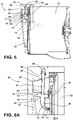
FIG. 5 is a side cross-sectional view of the water recirculation ofFIG. 4 taken at lines V-V; -
FIG. 6A is an enlarged cross-sectional view of the water recirculation assembly ofFIG. 5 taken at area VI; -
FIG. 6B is an enlarged cross-sectional view of a valve of the water recirculation assembly ofFIG 6A taken at area VIB; -
FIG. 7 is a rear perspective view of a water recirculation assembly of the present disclosure operably coupled to a drum illustrated in phantom; -
FIG. 8 is a front elevational view of an aspect of the water recirculation assembly; -
FIG. 9 is a schematic cross-sectional view of a laundry appliance of the present disclosure with an aspect of the water recirculation assembly and illustrating exemplary fluid streams; -
FIG. 10 is an enlarged cross-sectional view of a laundry appliance of the present disclosure with an aspect of the water recirculation assembly with an inlet tube in af frame; and -
FIG. 11 is a top perspective view of a water recirculation assembly of the present disclosure. - The components in the figures are not necessarily to scale, emphasis instead being placed upon illustrating the principles described herein.
- The present illustrated embodiments reside primarily in combinations of apparatus components related to a water recirculation assembly. Accordingly, the apparatus components have been represented, where appropriate, by conventional symbols in the drawings, showing only those specific details that are pertinent to understanding the embodiments of the present disclosure so as not to obscure the disclosure with details that will be readily apparent to those of ordinary skill in the art having the benefit of the description herein. Further, like numerals in the description and drawings represent like elements.
- For purposes of description herein, the terms "upper," "lower," "right," "left," "rear," "front," "vertical," "horizontal," and derivatives thereof shall relate to the disclosure as oriented in
FIG. 1 . Unless stated otherwise, the term "front" shall refer to the surface of the element closer to an intended viewer, and the term "rear" shall refer to the surface of the element further from the intended viewer. However, it is to be understood that the disclosure may assume various alternative orientations, except where expressly specified to the contrary. It is also to be understood that the specific devices and processes illustrated in the attached drawings, and described in the following specification are simply exemplary embodiments of the inventive concepts defined in the appended claims. Hence, specific dimensions and other physical characteristics relating to the embodiments disclosed herein are not to be considered as limiting, unless the claims expressly state otherwise. - The terms "including," "comprises," "comprising," or any other variation thereof, are intended to cover a non-exclusive inclusion, such that a process, method, article, or apparatus that comprises a list of elements does not include only those elements but may include other elements not expressly listed or inherent to such process, method, article, or apparatus. An element proceeded by "comprises a . . . " does not, without more constraints, preclude the existence of additional identical elements in the process, method, article, or apparatus that comprises the element.
- Referring to
FIGS. 1-11 ,reference numeral 10 generally designates a laundry appliance that includes acabinet 12 with apump 14. Adoor 16 is positioned proximate to thecabinet 12 and includes anouter frame 18 and acentral portion 20. Adrum 22 is positioned within thecabinet 12, and atub 24 is proximate to thedoor 16 and operably coupled to thedrum 22. Awater recirculation assembly 26 can be operably coupled to thecabinet 12 and thedoor 16. Thewater recirculation assembly 26 is also disposed proximate to thetub 24. Thewater recirculation assembly 26 includes afirst tube 28 that is operably coupled to thepump 14 and asecond tube 30 can be operably coupled to thedoor 16. Agap 32 can be defined between thefirst tube 28 and thesecond tube 30. - Referring to
FIGS. 1-3 , thecabinet 12 of thelaundry appliance 10 includes anaesthetic door 38 coupled to afront panel 40 that surrounds thedoor 16 and includes auser interface 42. Theaesthetic door 38 is coupled to thefront panel 40 of thecabinet 12, and thedoor 16 is coupled to thetub 24 proximate to thefront panel 40. Theaesthetic door 38 and thedoor 16 are operable between opened and closedpositions aesthetic door 38 and thedoor 16 may be a flat panel door, a fishbowl style door, or a combination thereof. Thedoor 16 is configured to provide access to thedrum 22 positioned within thecabinet 12 when thedoor 16 is in theopen position 44 and encloses thetub 24 and thedrum 22 when thedoor 16 is in the closedposition 46. Thedoor 16 includes thecentral portion 20 and theouter frame 18 disposed around thecentral portion 20. It is generally contemplated that thecentral portion 20 can be transparent. However, it is also contemplated that thecentral portion 20 may be opaque and/or translucent. - As mentioned above, the
cabinet 12 includes thepump 14, which is configured to collect aliquid 48 and ultimately circulate theliquid 48 to be disposed within thedrum 22, described in more detail below. Thepump 14 is generally housed within thecabinet 12 and is fluidly coupled to thewater recirculation assembly 26. Thepump 14 can be positioned within thecabinet 12 beneath thedrum 22 and includes ahose 50. Thehose 50 extends from thepump 14 and is routed toward thefirst tube 28. Theliquid 48 described herein is generally contemplated to be water, but may also include a combination of water and detergent, recycled water, or other liquids and chemistries typically collected and circulated by thepump 14. Thehose 50 dispenses the liquid 48 from thepump 14 to thefirst tube 28, described further below. - With further reference to
FIGS. 1-3 , aframe 52 is coupled to thetub 24 and generally surrounds thedoor 16 in theclosed position 46 of thedoor 16. Theframe 52 is disposed behind thefront panel 40 to conceal theframe 52, and thedoor 16 may generally flush with thecabinet 12, such that thedoor 16 may be generally aligned with thefront panel 40 and surrounded by theframe 52. Thefirst tube 28 is operably coupled to theframe 52. Thefirst tube 28 is generally fixed relative to theframe 52. Stated differently, thefirst tube 28 may be integrally formed with theframe 52 to the extent that thefirst tube 28 is disposed within theframe 52. Thecentral portion 20 of thedoor 16 is generally spaced apart from theframe 52. In this configuration, thefirst tube 28 is disposed within theframe 52 and is spaced apart from thesecond tube 30 that is operably coupled to thedoor 16. This general separation of theframe 52 and thecentral portion 20 of thedoor 16 also defines thegap 32 between thefirst tube 28 and thesecond tube 30. - As mentioned above, the
door 16 is operably coupled to thetub 24 proximate to thedrum 22. Thetub 24 and thedrum 22 define anopening 54 through which articles, such as clothing, are disposed within thedrum 22 to be processed. Thedoor 16 provides selective access to thedrum 22 via theopening 54. Thedoor 16 is configured to cover theopening 54 in theclosed position 46 of thedoor 16 and provide access to theopening 54 in theopen position 44 of thedoor 16. As described in more detail below, thedoor 16 may be in fluid communication with thedrum 22, such that the liquid 48 may enter thedrum 22 proximate to thedoor 16 and through theopening 54. - Referring to
FIGS. 3-6 , thefirst tube 28 of thewater recirculation assembly 26 is disposed within theframe 52 of thecabinet 12, and thesecond tube 30 of thewater recirculation assembly 26 is disposed within thedoor 16 proximate to thetub 24. Stated differently, thefirst tube 28 extends through theframe 52 toward thedoor 16, and thesecond tube 30 extends from thecentral portion 20 proximate to thefirst tube 28 through thecentral portion 20 toward thedrum 22. Thesecond tube 30 may be referred to as a water distribution feature and is configured to distribute the liquid 48 into thedrum 22. Thefirst tube 28 may be referred to as an inlet tube, and theinlet tube 28 includes alinear body 60 that includes afirst end 62 and asecond end 64. - The
inlet tube 28 also includes aninlet feature 66 that is operably coupled to thefirst end 62 of theinlet tube 28 and to thehose 50 of thepump 14. Theinlet feature 66 is configured to receive the liquid 48 from thepump 14 and deliver the liquid 48 through thefirst end 62 of theinlet tube 28. The liquid 48 passes from thefirst end 62 through thelinear body 60 and out thesecond end 64 of theinlet tube 28. The liquid 48 then passes from thesecond end 64 of theinlet tube 28, across thegap 32, and is received by thesecond tube 30. Stated differently, thesecond end 64 of thelinear body 60 is positioned proximate to thesecond tube 30 and directs the liquid 48 into thesecond tube 30 through thegap 32. The translation of the liquid 48 across thegap 32 is facilitated by gravity, such that the liquid 48 is directed into thesecond tube 30, at least in part due to gravity. Thesecond tube 30 includes a receivingend 68 proximate to thesecond end 64 of theinlet tube 28 and adistribution end 70 proximate to thedrum 22. - With further reference to
FIGS. 3-6B , it is generally contemplated that thedistribution end 70 is generally curved to direct or redirect the liquid 48 received by the receivingend 68 toward thedrum 22. Thesecond tube 30 also includes a curvedcentral body 72 between the receivingend 68 and thedistribution end 70 that promotes a laminar flow offluid 48 toward thedrum 22. As mentioned above, the receivingend 68 of thesecond tube 30 receives the liquid 48 from thefirst tube 28 via thesecond end 64 of thefirst tube 28. The liquid 48 enters thedrum 22 via thedistribution end 70 of thesecond tube 30, such that the liquid 48 is projected from thedistribution end 70 past thetub 24 and into thedrum 22. Thesecond tube 30 also includes avalve 74 disposed within thedistribution end 70 configured to direct the liquid 48 through thesecond tube 30 and into thedrum 22 while preventing backflow of the liquid 48 from thedrum 22 into thesecond tube 30. Thevalve 74 may be described as being a check valve meaning the liquid 48 can flow through thevalve 74 in one direction, toward thedrum 22. Thedoor 16 is operably coupled to thetub 24, such that thesecond tube 30 is, in turn, operably coupled to thetub 24 via thedoor 16. This configuration of thesecond tube 30 being coupled to thedoor 16 helps to further promote laminar flow of the liquid 48 toward thedrum 22. - It is generally contemplated that the
door 16 and thesecond tube 30 are configured to wobble, oscillate or otherwise move, with a movement path of thetub 24, such that thedoor 16 may move within thecabinet 12. It is also contemplated that thefirst tube 28 may have some movement along with thetub 24 as theframe 52 is operably coupled to thetub 24 and thefirst tube 28 is fixed within theframe 52. A first position of thewater recirculation assembly 26 is defined when thesecond tube 30 is centrally aligned to thefirst tube 28. In the first position, thesecond end 64 of thefirst tube 28 is concentrically aligned with the receivingend 68 of thesecond tube 30. As thedoor 16 moves with thetub 24, thesecond tube 30 is generally displaced from thefirst tube 28, such that thesecond tube 30 is defined in a second position of thewater recirculation assembly 26. While thesecond tube 30 is displaced, the receivingend 68 of thesecond tube 30 is still positioned beneath thefirst tube 28, such that thesecond tube 30 may still receive the liquid 48 in the second position. Specifically, the receivingend 68 of thesecond tube 30 has a larger opening than thesecond end 64 of thefirst tube 28. Stated differently, the receivingend 68 of thesecond tube 30 has a circumference C1 that is larger than a circumference C2 of thefirst tube 28. The second position is defined by thefirst tube 28 being generally offset or out of alignment with thesecond tube 30 as compared to the vertical alignment of the first andsecond tubes first tube 28 can still transfer the liquid 48 through thesecond tube 30 as a result of the size difference between thefirst tube 28 and thesecond tube 30. - Referring still to
FIGS. 3-6B , as thelaundry appliance 10 performs a cycle, thetub 24, theframe 52, and thedoor 16 wobble and oscillate such that thesecond tube 30 is generally misaligned, as mentioned above, with thefirst tube 28. Upon completion of the laundry cycle, the oscillations cease and thesecond tube 30 reenters the first position and is realigned with thefirst tube 28. Thelaundry appliance 10 may operate thewater recirculation assembly 26 to distribute additional liquid 48 through the first andsecond tubes drum 22, for example, during a rinse cycle. The routine may be repeated as few or as many times based on a selected laundry cycle and/or based on any potential cleanliness detection by internal sensors. - The separation of the first and
second tubes water recirculation assembly 26 by embedding thefirst tube 28 within theframe 54 and thesecond tube 30 within thedoor 16. Thewater recirculation assembly 26 provides an improved distribution of the liquid 48 by directly distributing the liquid 48 into thedrum 22 via thewater recirculation assembly 26. As such, thelaundry appliance 10 is generally free from bellows, which may maximize the overall cleanliness and useful life of thelaundry appliance 10. - Referring now to
FIGS. 7-11 , thewater recirculation assembly 26 described above is illustrated in an alternative configuration disposed between thetub 24 and thedrum 22. In this configuration, thesecond tube 30 may be referred to as a manifold tube and is coupled to theinlet tube 28. Themanifold tube 30 includes a circumferential body 80 that defines a plurality ofapertures 82 along at least a portion of the circumferential body 80. It is generally contemplated that theinlet tube 28 may be coupled to theframe 52, as described above, or theinlet tube 28 may be integrated with thetub 24, described below. - The plurality of
apertures 82 may include any number ofapertures 82 defined along the circumferential body 80, such thatmore apertures 82 orfewer apertures 82 than those illustrated may be defined depending on the size and configuration of thelaundry appliance 10. Theapertures 82 may be circular, rectangular, triangular, or any other shape generally known in the art. Theapertures 82 can be evenly spaced along the circumferential body 80 or may, alternatively, be grouped at predefined portions along the circumferential body 80. If theapertures 82 are grouped, the portions at which theapertures 82 are defined may maximize the distribution of the liquid 48 to particular areas within thedrum 22 to improve the overall efficiency of thelaundry appliance 10. - As illustrated, the plurality of
apertures 82 are generally evenly spaced along the circumferential body 80. The circumferential body 80 is illustrated as a circular body. Additionally or alternatively, the circumferential body 80 may be crescent shaped or any other radial configuration that at least partially extends around theopening 54 defined by thedrum 22 and is generally congruent with the shape of theopening 54. It is also contemplated that themanifold tube 30 is generally concentrically aligned with thedrum 22, such that themanifold tube 30 is aligned with theopening 54 of thedrum 22. Thus, thedrum 22 generally surrounds, or extends beyond, themanifold tube 30. - With further reference to
FIGS. 7-11 , aspace 84 is defined between thetub 24 and thedrum 22, such that thewater recirculation assembly 26 is disposed within thespace 84 between thetub 24 and thedrum 22. As mentioned above, theframe 52 is operably coupled to thetub 24 proximate to thedoor 16 and at least partially defines theopening 54. Theouter frame 18 of thedoor 16 is generally disposed proximate to theframe 52 and thetub 24. As described in more detail below, thewater recirculation assembly 26 can be operably coupled to theframe 54 and thetub 24. As mentioned above, theinlet tube 28 is operably coupled to thepump 14 via theinlet feature 66 of thefirst end 62 of theinlet tube 28. Theinlet tube 28 directs the liquid 48 from thepump 14 through themanifold tube 30. Thewater recirculation assembly 26 is configured to dispense the liquid 48 from thepump 14 into thedrum 22, which is facilitated by the positioning of thewater recirculation assembly 26 in thespace 84 defined between thetub 24 and thedrum 22. - As illustrated in
FIG. 9 , theinlet feature 66, mentioned above, is operably coupled to thefirst end 62 of theinlet tube 28 and is configured to direct the liquid 48 from thepump 14 to theinlet tube 28. Theinlet tube 28 can be integrally formed with thetub 24, such that thelinear body 60 is defined by thetub 24. It is further contemplated that theinlet tube 28 is directly coupled to themanifold tube 30 at the receivingend 68 of themanifold tube 30. As illustrated inFIG. 9 , the receivingend 68 of themanifold tube 30 is coupled to the circumferential body 80 at a receivingopening 88 of themanifold tube 30. The receivingopening 88 is defined by the circumferential body 80 and is generally proximate to thesecond end 64 of theinlet tube 28. It is also contemplated that thesecond end 64 of theinlet tube 28 may be integrally formed with the circumferential body 80 of themanifold tube 30 proximate to the receivingopening 88. - In an alternate configuration illustrated in
FIG. 10 , theinlet tube 28 is disposed within theframe 52, as described above, and themanifold tube 30 is disposed in thespace 84 between thetub 24 and thedrum 22. Theinlet tube 28 illustrated inFIG. 10 includes an arcuate body 90 so theinlet tube 28 is directed toward thetub 24. Thesecond end 64 of theinlet tube 28 is operably coupled to the receivingend 68 of themanifold tube 30 in thespace 84 between thetub 24 and thedrum 22. It is generally contemplated that theinlet tube 28 may extend through thetub 24 to couple to themanifold tube 30. It is also contemplated that theinlet tube 28 is disposed proximate to the receivingend 68 of themanifold tube 30, but may remain uncoupled from themanifold tube 30. - As illustrated in
FIG. 11 and as mentioned above, themanifold tube 30 has a generally circumferential configuration that can be concentrically aligned with thedrum 22. It is generally contemplated that the configuration of thewater recirculation assembly 26, as illustrated inFIGS. 7-11 , is generally fixed relative to thetub 24. Thewater recirculation assembly 26 is generally constructed from a pliable material, such as rubber, and is generally flexible and resilient to minimize the overall wear of thewater recirculation assembly 26. The flexibility and pliability of thewater recirculation assembly 26 is also configured to increase the useful life of thewater recirculation assembly 26. - Conventional appliances include a bellows that directs water into the appliance. Over time, the bellows may wear down and may build up a residue. Thus, users of conventional appliances may need to repeatedly clean the bellows to maintain the overall function and cleanliness of the appliance.
- Referring again to
FIGS. 1-11 , thelaundry appliance 10 described herein is generally free from a bellows that directs the liquid 48 into thedrum 22. Rather, thewater recirculation assembly 26 is configured to dispense the liquid 48 from thepump 14 into thedrum 22. Thewater recirculation assembly 26 includes thefirst tube 28 and thesecond tube 30, which are fluidly coupled to translate the liquid 48. The configuration of the first andsecond tubes laundry appliance 10. For example, thefirst tube 28 may be disposed within thecabinet 12 and thesecond tube 30 may be disposed within thedoor 16 defining thegap 32 therebetween. Additionally or alternatively, thefirst tube 28 may be directly coupled to thesecond tube 30, such that the first andsecond tubes water recirculation assembly 26 provides improved liquid distribution of thelaundry appliance 10. - The invention disclosed herein is further summarized in the following paragraphs and is further characterized by combinations of any and all of the various aspects described therein.
- According to one aspect of the present disclosure, a laundry appliance includes a cabinet that includes a pump and a door proximate to the cabinet. A tub is disposed within the cabinet and is proximate to the door and is operably coupled to the drum. A water recirculation assembly is operably coupled to the cabinet and the door and is disposed proximate to the tub. The water recirculation assembly includes a first tube that is attached to the cabinet and is operably coupled to the pump, a second tube that is operably coupled to the door, and a gap that is defined between the first tube and the second tube.
- According to another aspect, a second tube includes a water distribution feature and a first tube includes an inlet feature.
- According to another aspect, a water distribution feature is disposed within a door and is configured to distribute a liquid into a tub.
- According to another aspect, a second tube has a receiving end that is proximate to a first tube and a curved distribution end that is proximate to a tub. The receiving end at least partially defines a gap.
- According to another aspect, a receiving end of a second tube receives a liquid from a first tube, and a liquid enters a drum via a curved distribution end.
- According to another aspect, a door and a second tube are coupled to a tub and are configured to move with the tub.
- According to another aspect, a second tube is integrally formed with a door, and a first end of the second tube is proximate to a first tube, a central body of the second tube is disposed within the door, and a second end of the second tube extends toward a drum.
- According to another aspect of the present disclosure, a laundry appliance includes a cabinet that includes a pump. A drum is disposed within the cabinet and a tub is operably coupled to the drum. A water recirculation assembly is coupled to the tub. The water recirculation assembly includes an inlet tube, and a manifold tube is coupled to the inlet tube. The manifold tube defines a plurality of apertures along at least a portion of the manifold tube.
- According to another aspect, an inlet tube is operably coupled to a pump.
- According to another aspect, a space is defined between a tub and a drum, and a water recirculation assembly is disposed within the space between the tub and the drum.
- According to another aspect, a plurality of apertures are configured to direct a liquid into a drum.
- According to another aspect, a tub includes a front covering, and a water recirculation assembly is coupled to the front covering of the tub.
- According to another aspect, an inlet tube includes a linear body that has a first end and is coupled to a pump, and a second end that is coupled to a manifold tube. The manifold tube includes a circumferential body that is concentrically aligned with a drum.
- According to yet another aspect of the present disclosure, a laundry appliance includes a cabinet that includes a pump. A drum is disposed within the cabinet and a tub is operably coupled to the drum and is disposed proximate to the cabinet. A water recirculation assembly is operably coupled to the pump. The water recirculation assembly includes a first tube that is operably coupled to the pump within the cabinet, a second tube that is fluidly coupled to the first tube, and a gap that is defined between the first tube and the second tube.
- According to another aspect, a door is operably coupled to a tub, and a second tube is integrally formed with the door that is proximate to the tub.
- According to another aspect, a second tube includes a receiving end that is proximate to a first tube and a curved distribution end that is proximate to a tub, and a first tube includes a first end and a second end.
- According to another aspect, a receiving end of a second tube receives a liquid from a first tube, and the liquid enters a drum via a curved distribution end.
- According to another aspect, a gap is defined between a second end of a first tube and a receiving end of a second tube.
- According to another aspect, a first end of a second tube is proximate to a first tube, a central body of the second tube is disposed within a door, and a second end of the second tube extends toward a drum.
- According to another aspect, a door and a second tube are coupled to a tub and are configured to move with the tub.
Claims (15)
- A laundry appliance (10), comprising:a cabinet (12) including a pump (14);a drum (22) disposed within the cabinet (12);a tub (24) operably coupled to the drum (22) and disposed proximate to the cabinet (12); anda water recirculation assembly (26) operably coupled to the pump (14), the water recirculation assembly (26) including:a first tube (28) operably coupled to the pump (14);a second tube (30) fluidly coupled to the first tube (28) and including a valve (74) disposed proximate to the drum (22); anda gap (32) defined between the first tube (28) and the second tube (30).
- The laundry appliance (10) of claim 1, further comprising:a frame (52) operably coupled to the tub (24), wherein the first tube (28) is integrally formed with the frame (52) proximate to the second tube (30); anda door (16) operably coupled to the tub (24), wherein the second tube (30) is integrally formed with the door (16) proximate to the tub (24).
- The laundry appliance (10) of claim 2, wherein the door (16) and the second tube (30) are coupled to the tub (24) and are configured to move with the tub (24), and preferably wherein the frame (52) and the first tube (28) are coupled to the tub (24) and are configured to move with the tub (24).
- The laundry appliance (10) of either of claims 2 and 3, wherein a receiving end (68) of the second tube (30) is proximate to the first tube (28), a central body (72) of the second tube (30) is disposed within the door (16), and a distribution end (70) of the second tube (30) extends toward the drum (22).
- The laundry appliance (10) of claim 4, wherein the receiving end (68) of the second tube (30) has a circumference larger than a circumference of the first tube (28).
- The laundry appliance (10) of either of claims 4 and 5, wherein the first tube (28) includes a first end (62) and a second end (64), and wherein the second end (64) of the first tube (28) is proximate the receiving end (68) of the second tube (30).
- The laundry appliance (10) of any one of claims 4-6, wherein the receiving end (68) of the second tube (30) receives a liquid (48) from the first tube (28), and wherein the liquid (48) enters the drum (22) via the valve (74) disposed in the curved distribution end (70).
- The laundry appliance (10) of any one of claims 4-7, wherein the receiving end (68) of the second tube (30) at least partially defines the gap (32) and receives the liquid (48) from the first tube (28), and wherein the liquid (48) enters the drum (22) via the curved distribution end (70).
- The laundry appliance (10) of any one of claims 1-8, wherein the second tube (30) comprises a water distribution feature and the first tube (28) comprises an inlet feature (66).
- A laundry appliance (10), comprising:a cabinet (12) including a pump (14);a drum (22) disposed within the cabinet (12);a tub (24) operably coupled to the drum (22);a frame (52) operably coupled to the tub (24); anda water recirculation assembly (26) coupled to the tub (24), the water recirculation assembly (26) including:an inlet tube (28); anda manifold tube (30) coupled to the inlet tube (28), the manifold tube (30) defining a plurality of apertures (82) along at least a portion of the manifold tube (30).
- The laundry appliance (10) of claim 10, wherein a space (84) is defined between the tub (24) and the drum (22), and wherein the water recirculation assembly (26) is disposed within the space (84) between the tub (24) and the drum (22).
- The laundry appliance (10) of claim 10, wherein the inlet tube (28) is defined by the tub (24) and is operably coupled to the manifold tube (30) within the space (84) defined between the tub (24) and the drum (22).
- The laundry appliance (10) of either of claims 10-12, wherein the plurality of apertures (82) are configured to direct a liquid (48) into the drum (22).
- The laundry appliance (10) of any one of claims 12-14, wherein the inlet tube (28) includes a linear body (60) having a first end (62) coupled to the pump (14) and a second end (64) coupled to the manifold tube (30).
- The laundry appliance (10) of any one of claims 10-14, wherein the manifold tube (30) includes a circumferential body (80) concentrically aligned with the drum (22).
Applications Claiming Priority (1)
| Application Number | Priority Date | Filing Date | Title |
|---|---|---|---|
| US16/953,934 US11725331B2 (en) | 2020-11-20 | 2020-11-20 | Water recirculation assembly for a laundry appliance |
Publications (2)
| Publication Number | Publication Date |
|---|---|
| EP4001495A1 true EP4001495A1 (en) | 2022-05-25 |
| EP4001495B1 EP4001495B1 (en) | 2023-10-04 |
Family
ID=78598879
Family Applications (1)
| Application Number | Title | Priority Date | Filing Date |
|---|---|---|---|
| EP21207653.3A Active EP4001495B1 (en) | 2020-11-20 | 2021-11-10 | Water recirculation assembly for a laundry appliance |
Country Status (3)
| Country | Link |
|---|---|
| US (2) | US11725331B2 (en) |
| EP (1) | EP4001495B1 (en) |
| CN (1) | CN114517393A (en) |
Cited By (1)
| Publication number | Priority date | Publication date | Assignee | Title |
|---|---|---|---|---|
| US12553171B2 (en) * | 2022-09-22 | 2026-02-17 | Whirlpool Corporation | Recirculation hose routing for a laundry appliance |
Families Citing this family (1)
| Publication number | Priority date | Publication date | Assignee | Title |
|---|---|---|---|---|
| US12410550B2 (en) * | 2022-11-28 | 2025-09-09 | Haier Us Appliance Solutions, Inc. | Laundry appliance door for treatment of non-moving articles |
Citations (6)
| Publication number | Priority date | Publication date | Assignee | Title |
|---|---|---|---|---|
| ES2113792A1 (en) * | 1993-09-06 | 1998-05-01 | Bosch Siemens Hausgeraete | Front-loading drum-type washing machine |
| EP1634987A1 (en) * | 2004-09-08 | 2006-03-15 | LG Electronics, Inc. | Washing machine |
| ES2446115A2 (en) * | 2012-09-06 | 2014-03-06 | BSH Electrodomésticos España S.A. | Annular portal assembly for a front-loading washing machine with a laundry soaking system and washing machine comprising the assembly |
| EP2711452A1 (en) * | 2012-09-25 | 2014-03-26 | Miele & Cie. KG | Washing machine with a tub and a circulation device |
| US20150121969A1 (en) * | 2013-11-07 | 2015-05-07 | Samsung Electronics Co., Ltd. | Washing machine |
| EP2902541A1 (en) * | 2014-01-29 | 2015-08-05 | LG Electronics Inc. | Washing machine having a plurality of tubs |
Family Cites Families (16)
| Publication number | Priority date | Publication date | Assignee | Title |
|---|---|---|---|---|
| EP0942093B1 (en) * | 1998-03-12 | 2004-12-29 | Matsushita Electric Industrial Co., Ltd. | Electric washer-dryer |
| KR100565479B1 (en) | 2000-03-30 | 2006-03-30 | 엘지전자 주식회사 | Drum Washing Machine with Laundry |
| KR100743707B1 (en) * | 2005-02-03 | 2007-07-30 | 엘지전자 주식회사 | Tub integral drum washing machine with drying unit |
| KR101461390B1 (en) | 2008-11-20 | 2014-11-13 | 동부대우전자 주식회사 | Drum washing machine |
| EP2546403A1 (en) * | 2011-07-14 | 2013-01-16 | Electrolux Home Products Corporation N.V. | Drum washing machine |
| WO2013091288A1 (en) * | 2011-12-19 | 2013-06-27 | 海尔集团公司 | Device and method for cleaning observation window and window spacer sealing ring, and washing machine applying the same |
| KR102032845B1 (en) * | 2013-02-13 | 2019-10-16 | 엘지전자 주식회사 | Laundry Treating Apparatus |
| DE102016216391A1 (en) | 2016-08-31 | 2018-03-01 | BSH Hausgeräte GmbH | Laundry care device with a diversion device |
| US11255039B2 (en) | 2016-12-28 | 2022-02-22 | Lg Electronics Inc. | Washing machine |
| DE102018104033A1 (en) | 2018-02-22 | 2019-08-22 | Miele & Cie. Kg | Washing machine with circulating device |
| EP3755835B1 (en) * | 2018-02-22 | 2023-08-23 | Electrolux Appliances Aktiebolag | Laundry washing machine equipped with a liquid supply line |
| CN110387707B (en) | 2018-04-16 | 2021-12-03 | 青岛海尔洗涤电器有限公司 | Roller washing machine and door body and spraying system thereof |
| KR102638187B1 (en) | 2018-06-04 | 2024-02-16 | 엘지전자 주식회사 | Washing machine with a conduit for supplying water to nozzles at gasket and manufacturing method of the conduit |
| US11066775B2 (en) | 2018-09-14 | 2021-07-20 | Electrolux Appliances Aktiebolag | Method and apparatus for cleaning laundry |
| KR102628098B1 (en) * | 2019-02-01 | 2024-01-23 | 엘지전자 주식회사 | Laundry Treatment Machine |
| KR102628103B1 (en) * | 2019-02-01 | 2024-01-23 | 엘지전자 주식회사 | Laundry Treatment Machine |
-
2020
- 2020-11-20 US US16/953,934 patent/US11725331B2/en active Active
-
2021
- 2021-11-10 EP EP21207653.3A patent/EP4001495B1/en active Active
- 2021-11-17 CN CN202111362722.8A patent/CN114517393A/en active Pending
-
2023
- 2023-06-07 US US18/330,598 patent/US20230313435A1/en not_active Abandoned
Patent Citations (6)
| Publication number | Priority date | Publication date | Assignee | Title |
|---|---|---|---|---|
| ES2113792A1 (en) * | 1993-09-06 | 1998-05-01 | Bosch Siemens Hausgeraete | Front-loading drum-type washing machine |
| EP1634987A1 (en) * | 2004-09-08 | 2006-03-15 | LG Electronics, Inc. | Washing machine |
| ES2446115A2 (en) * | 2012-09-06 | 2014-03-06 | BSH Electrodomésticos España S.A. | Annular portal assembly for a front-loading washing machine with a laundry soaking system and washing machine comprising the assembly |
| EP2711452A1 (en) * | 2012-09-25 | 2014-03-26 | Miele & Cie. KG | Washing machine with a tub and a circulation device |
| US20150121969A1 (en) * | 2013-11-07 | 2015-05-07 | Samsung Electronics Co., Ltd. | Washing machine |
| EP2902541A1 (en) * | 2014-01-29 | 2015-08-05 | LG Electronics Inc. | Washing machine having a plurality of tubs |
Cited By (1)
| Publication number | Priority date | Publication date | Assignee | Title |
|---|---|---|---|---|
| US12553171B2 (en) * | 2022-09-22 | 2026-02-17 | Whirlpool Corporation | Recirculation hose routing for a laundry appliance |
Also Published As
| Publication number | Publication date |
|---|---|
| US20230313435A1 (en) | 2023-10-05 |
| CN114517393A (en) | 2022-05-20 |
| EP4001495B1 (en) | 2023-10-04 |
| US11725331B2 (en) | 2023-08-15 |
| US20220162792A1 (en) | 2022-05-26 |
Similar Documents
| Publication | Publication Date | Title |
|---|---|---|
| US11851804B2 (en) | Washing machine | |
| US20230313435A1 (en) | Water recirculation assembly for a laundry appliance | |
| US12077898B2 (en) | Washing machine | |
| US9328450B2 (en) | Washing machine and detergent case thereof | |
| US11834769B2 (en) | Laundry treating appliance with dispenser having a siphon cap | |
| CN107771229B (en) | washing machine | |
| KR102854972B1 (en) | Washing machine having the detergent feeding device | |
| CN115262180B (en) | washing machine | |
| CN113677249B (en) | dishwasher | |
| EP2468169B1 (en) | Table top dishwasher | |
| US20180251928A1 (en) | Washing machine | |
| US7192102B2 (en) | Control panel assembly | |
| US8857034B2 (en) | Method for manufacturing a dishwasher appliance | |
| US11484176B2 (en) | Dishwasher | |
| KR100496002B1 (en) | Household Washing Machine | |
| EP1201981A1 (en) | Outlet hose construction for electric household appliances such as washing machines, dish-washers and the like | |
| US20180363224A1 (en) | Wall mounted washing machine and water supply fittings thereof | |
| US20240102228A1 (en) | Recirculation hose routing for a laundry appliance | |
| US20060060223A1 (en) | Dishwasher | |
| CN115262179B (en) | washing machine | |
| US11696414B2 (en) | Laundry appliance | |
| JPH0321744Y2 (en) | ||
| EP3669740B1 (en) | Dishwasher | |
| KR20180136093A (en) | Wall mounted washing machine and water supply valve assembly | |
| US10612181B2 (en) | Laundry treating appliance with dispenser having domed bottom |
Legal Events
| Date | Code | Title | Description |
|---|---|---|---|
| PUAI | Public reference made under article 153(3) epc to a published international application that has entered the european phase |
Free format text: ORIGINAL CODE: 0009012 |
|
| STAA | Information on the status of an ep patent application or granted ep patent |
Free format text: STATUS: THE APPLICATION HAS BEEN PUBLISHED |
|
| AK | Designated contracting states |
Kind code of ref document: A1 Designated state(s): AL AT BE BG CH CY CZ DE DK EE ES FI FR GB GR HR HU IE IS IT LI LT LU LV MC MK MT NL NO PL PT RO RS SE SI SK SM TR |
|
| STAA | Information on the status of an ep patent application or granted ep patent |
Free format text: STATUS: REQUEST FOR EXAMINATION WAS MADE |
|
| 17P | Request for examination filed |
Effective date: 20221024 |
|
| RBV | Designated contracting states (corrected) |
Designated state(s): AL AT BE BG CH CY CZ DE DK EE ES FI FR GB GR HR HU IE IS IT LI LT LU LV MC MK MT NL NO PL PT RO RS SE SI SK SM TR |
|
| RAP3 | Party data changed (applicant data changed or rights of an application transferred) |
Owner name: WHIRLPOOL CORPORATION |
|
| GRAP | Despatch of communication of intention to grant a patent |
Free format text: ORIGINAL CODE: EPIDOSNIGR1 |
|
| STAA | Information on the status of an ep patent application or granted ep patent |
Free format text: STATUS: GRANT OF PATENT IS INTENDED |
|
| RIC1 | Information provided on ipc code assigned before grant |
Ipc: D06F 37/26 20060101ALN20230627BHEP Ipc: D06F 39/08 20060101AFI20230627BHEP |
|
| INTG | Intention to grant announced |
Effective date: 20230720 |
|
| GRAS | Grant fee paid |
Free format text: ORIGINAL CODE: EPIDOSNIGR3 |
|
| GRAA | (expected) grant |
Free format text: ORIGINAL CODE: 0009210 |
|
| STAA | Information on the status of an ep patent application or granted ep patent |
Free format text: STATUS: THE PATENT HAS BEEN GRANTED |
|
| AK | Designated contracting states |
Kind code of ref document: B1 Designated state(s): AL AT BE BG CH CY CZ DE DK EE ES FI FR GB GR HR HU IE IS IT LI LT LU LV MC MK MT NL NO PL PT RO RS SE SI SK SM TR |
|
| P01 | Opt-out of the competence of the unified patent court (upc) registered |
Effective date: 20230828 |
|
| REG | Reference to a national code |
Ref country code: GB Ref legal event code: FG4D |
|
| REG | Reference to a national code |
Ref country code: CH Ref legal event code: EP |
|
| REG | Reference to a national code |
Ref country code: IE Ref legal event code: FG4D |
|
| REG | Reference to a national code |
Ref country code: DE Ref legal event code: R096 Ref document number: 602021005618 Country of ref document: DE |
|
| REG | Reference to a national code |
Ref country code: LT Ref legal event code: MG9D |
|
| PGFP | Annual fee paid to national office [announced via postgrant information from national office to epo] |
Ref country code: FR Payment date: 20231123 Year of fee payment: 3 Ref country code: DE Payment date: 20231127 Year of fee payment: 3 |
|
| REG | Reference to a national code |
Ref country code: AT Ref legal event code: MK05 Ref document number: 1617869 Country of ref document: AT Kind code of ref document: T Effective date: 20231004 |
|
| PG25 | Lapsed in a contracting state [announced via postgrant information from national office to epo] |
Ref country code: NL Free format text: LAPSE BECAUSE OF FAILURE TO SUBMIT A TRANSLATION OF THE DESCRIPTION OR TO PAY THE FEE WITHIN THE PRESCRIBED TIME-LIMIT Effective date: 20231004 |
|
| PG25 | Lapsed in a contracting state [announced via postgrant information from national office to epo] |
Ref country code: GR Free format text: LAPSE BECAUSE OF FAILURE TO SUBMIT A TRANSLATION OF THE DESCRIPTION OR TO PAY THE FEE WITHIN THE PRESCRIBED TIME-LIMIT Effective date: 20240105 |
|
| PG25 | Lapsed in a contracting state [announced via postgrant information from national office to epo] |
Ref country code: IS Free format text: LAPSE BECAUSE OF FAILURE TO SUBMIT A TRANSLATION OF THE DESCRIPTION OR TO PAY THE FEE WITHIN THE PRESCRIBED TIME-LIMIT Effective date: 20240204 |
|
| PG25 | Lapsed in a contracting state [announced via postgrant information from national office to epo] |
Ref country code: LT Free format text: LAPSE BECAUSE OF FAILURE TO SUBMIT A TRANSLATION OF THE DESCRIPTION OR TO PAY THE FEE WITHIN THE PRESCRIBED TIME-LIMIT Effective date: 20231004 |
|
| PG25 | Lapsed in a contracting state [announced via postgrant information from national office to epo] |
Ref country code: AT Free format text: LAPSE BECAUSE OF FAILURE TO SUBMIT A TRANSLATION OF THE DESCRIPTION OR TO PAY THE FEE WITHIN THE PRESCRIBED TIME-LIMIT Effective date: 20231004 |
|
| PG25 | Lapsed in a contracting state [announced via postgrant information from national office to epo] |
Ref country code: ES Free format text: LAPSE BECAUSE OF FAILURE TO SUBMIT A TRANSLATION OF THE DESCRIPTION OR TO PAY THE FEE WITHIN THE PRESCRIBED TIME-LIMIT Effective date: 20231004 |
|
| PG25 | Lapsed in a contracting state [announced via postgrant information from national office to epo] |
Ref country code: LT Free format text: LAPSE BECAUSE OF FAILURE TO SUBMIT A TRANSLATION OF THE DESCRIPTION OR TO PAY THE FEE WITHIN THE PRESCRIBED TIME-LIMIT Effective date: 20231004 Ref country code: IS Free format text: LAPSE BECAUSE OF FAILURE TO SUBMIT A TRANSLATION OF THE DESCRIPTION OR TO PAY THE FEE WITHIN THE PRESCRIBED TIME-LIMIT Effective date: 20240204 Ref country code: GR Free format text: LAPSE BECAUSE OF FAILURE TO SUBMIT A TRANSLATION OF THE DESCRIPTION OR TO PAY THE FEE WITHIN THE PRESCRIBED TIME-LIMIT Effective date: 20240105 Ref country code: ES Free format text: LAPSE BECAUSE OF FAILURE TO SUBMIT A TRANSLATION OF THE DESCRIPTION OR TO PAY THE FEE WITHIN THE PRESCRIBED TIME-LIMIT Effective date: 20231004 Ref country code: BG Free format text: LAPSE BECAUSE OF FAILURE TO SUBMIT A TRANSLATION OF THE DESCRIPTION OR TO PAY THE FEE WITHIN THE PRESCRIBED TIME-LIMIT Effective date: 20240104 Ref country code: AT Free format text: LAPSE BECAUSE OF FAILURE TO SUBMIT A TRANSLATION OF THE DESCRIPTION OR TO PAY THE FEE WITHIN THE PRESCRIBED TIME-LIMIT Effective date: 20231004 Ref country code: PT Free format text: LAPSE BECAUSE OF FAILURE TO SUBMIT A TRANSLATION OF THE DESCRIPTION OR TO PAY THE FEE WITHIN THE PRESCRIBED TIME-LIMIT Effective date: 20240205 |
|
| PG25 | Lapsed in a contracting state [announced via postgrant information from national office to epo] |
Ref country code: SE Free format text: LAPSE BECAUSE OF FAILURE TO SUBMIT A TRANSLATION OF THE DESCRIPTION OR TO PAY THE FEE WITHIN THE PRESCRIBED TIME-LIMIT Effective date: 20231004 Ref country code: RS Free format text: LAPSE BECAUSE OF FAILURE TO SUBMIT A TRANSLATION OF THE DESCRIPTION OR TO PAY THE FEE WITHIN THE PRESCRIBED TIME-LIMIT Effective date: 20231004 Ref country code: PL Free format text: LAPSE BECAUSE OF FAILURE TO SUBMIT A TRANSLATION OF THE DESCRIPTION OR TO PAY THE FEE WITHIN THE PRESCRIBED TIME-LIMIT Effective date: 20231004 Ref country code: NO Free format text: LAPSE BECAUSE OF FAILURE TO SUBMIT A TRANSLATION OF THE DESCRIPTION OR TO PAY THE FEE WITHIN THE PRESCRIBED TIME-LIMIT Effective date: 20240104 Ref country code: LV Free format text: LAPSE BECAUSE OF FAILURE TO SUBMIT A TRANSLATION OF THE DESCRIPTION OR TO PAY THE FEE WITHIN THE PRESCRIBED TIME-LIMIT Effective date: 20231004 Ref country code: HR Free format text: LAPSE BECAUSE OF FAILURE TO SUBMIT A TRANSLATION OF THE DESCRIPTION OR TO PAY THE FEE WITHIN THE PRESCRIBED TIME-LIMIT Effective date: 20231004 |
|
| REG | Reference to a national code |
Ref country code: DE Ref legal event code: R097 Ref document number: 602021005618 Country of ref document: DE |
|
| PG25 | Lapsed in a contracting state [announced via postgrant information from national office to epo] |
Ref country code: DK Free format text: LAPSE BECAUSE OF FAILURE TO SUBMIT A TRANSLATION OF THE DESCRIPTION OR TO PAY THE FEE WITHIN THE PRESCRIBED TIME-LIMIT Effective date: 20231004 |
|
| PG25 | Lapsed in a contracting state [announced via postgrant information from national office to epo] |
Ref country code: LU Free format text: LAPSE BECAUSE OF NON-PAYMENT OF DUE FEES Effective date: 20231110 |
|
| PG25 | Lapsed in a contracting state [announced via postgrant information from national office to epo] |
Ref country code: CZ Free format text: LAPSE BECAUSE OF FAILURE TO SUBMIT A TRANSLATION OF THE DESCRIPTION OR TO PAY THE FEE WITHIN THE PRESCRIBED TIME-LIMIT Effective date: 20231004 |
|
| PG25 | Lapsed in a contracting state [announced via postgrant information from national office to epo] |
Ref country code: SK Free format text: LAPSE BECAUSE OF FAILURE TO SUBMIT A TRANSLATION OF THE DESCRIPTION OR TO PAY THE FEE WITHIN THE PRESCRIBED TIME-LIMIT Effective date: 20231004 |
|
| PG25 | Lapsed in a contracting state [announced via postgrant information from national office to epo] |
Ref country code: SM Free format text: LAPSE BECAUSE OF FAILURE TO SUBMIT A TRANSLATION OF THE DESCRIPTION OR TO PAY THE FEE WITHIN THE PRESCRIBED TIME-LIMIT Effective date: 20231004 Ref country code: SK Free format text: LAPSE BECAUSE OF FAILURE TO SUBMIT A TRANSLATION OF THE DESCRIPTION OR TO PAY THE FEE WITHIN THE PRESCRIBED TIME-LIMIT Effective date: 20231004 Ref country code: RO Free format text: LAPSE BECAUSE OF FAILURE TO SUBMIT A TRANSLATION OF THE DESCRIPTION OR TO PAY THE FEE WITHIN THE PRESCRIBED TIME-LIMIT Effective date: 20231004 Ref country code: LU Free format text: LAPSE BECAUSE OF NON-PAYMENT OF DUE FEES Effective date: 20231110 Ref country code: EE Free format text: LAPSE BECAUSE OF FAILURE TO SUBMIT A TRANSLATION OF THE DESCRIPTION OR TO PAY THE FEE WITHIN THE PRESCRIBED TIME-LIMIT Effective date: 20231004 Ref country code: DK Free format text: LAPSE BECAUSE OF FAILURE TO SUBMIT A TRANSLATION OF THE DESCRIPTION OR TO PAY THE FEE WITHIN THE PRESCRIBED TIME-LIMIT Effective date: 20231004 Ref country code: CZ Free format text: LAPSE BECAUSE OF FAILURE TO SUBMIT A TRANSLATION OF THE DESCRIPTION OR TO PAY THE FEE WITHIN THE PRESCRIBED TIME-LIMIT Effective date: 20231004 |
|
| REG | Reference to a national code |
Ref country code: BE Ref legal event code: MM Effective date: 20231130 |
|
| PLBE | No opposition filed within time limit |
Free format text: ORIGINAL CODE: 0009261 |
|
| STAA | Information on the status of an ep patent application or granted ep patent |
Free format text: STATUS: NO OPPOSITION FILED WITHIN TIME LIMIT |
|
| PG25 | Lapsed in a contracting state [announced via postgrant information from national office to epo] |
Ref country code: MC Free format text: LAPSE BECAUSE OF FAILURE TO SUBMIT A TRANSLATION OF THE DESCRIPTION OR TO PAY THE FEE WITHIN THE PRESCRIBED TIME-LIMIT Effective date: 20231004 |
|
| PG25 | Lapsed in a contracting state [announced via postgrant information from national office to epo] |
Ref country code: MC Free format text: LAPSE BECAUSE OF FAILURE TO SUBMIT A TRANSLATION OF THE DESCRIPTION OR TO PAY THE FEE WITHIN THE PRESCRIBED TIME-LIMIT Effective date: 20231004 |
|
| 26N | No opposition filed |
Effective date: 20240705 |
|
| REG | Reference to a national code |
Ref country code: IE Ref legal event code: MM4A |
|
| PG25 | Lapsed in a contracting state [announced via postgrant information from national office to epo] |
Ref country code: IE Free format text: LAPSE BECAUSE OF NON-PAYMENT OF DUE FEES Effective date: 20231110 |
|
| PG25 | Lapsed in a contracting state [announced via postgrant information from national office to epo] |
Ref country code: BE Free format text: LAPSE BECAUSE OF NON-PAYMENT OF DUE FEES Effective date: 20231130 |
|
| PG25 | Lapsed in a contracting state [announced via postgrant information from national office to epo] |
Ref country code: SI Free format text: LAPSE BECAUSE OF FAILURE TO SUBMIT A TRANSLATION OF THE DESCRIPTION OR TO PAY THE FEE WITHIN THE PRESCRIBED TIME-LIMIT Effective date: 20231004 |
|
| PG25 | Lapsed in a contracting state [announced via postgrant information from national office to epo] |
Ref country code: SI Free format text: LAPSE BECAUSE OF FAILURE TO SUBMIT A TRANSLATION OF THE DESCRIPTION OR TO PAY THE FEE WITHIN THE PRESCRIBED TIME-LIMIT Effective date: 20231004 Ref country code: IE Free format text: LAPSE BECAUSE OF NON-PAYMENT OF DUE FEES Effective date: 20231110 Ref country code: BE Free format text: LAPSE BECAUSE OF NON-PAYMENT OF DUE FEES Effective date: 20231130 |
|
| PGFP | Annual fee paid to national office [announced via postgrant information from national office to epo] |
Ref country code: IT Payment date: 20241130 Year of fee payment: 4 |
|
| REG | Reference to a national code |
Ref country code: DE Ref legal event code: R119 Ref document number: 602021005618 Country of ref document: DE |
|
| REG | Reference to a national code |
Ref country code: CH Ref legal event code: PL |
|
| PG25 | Lapsed in a contracting state [announced via postgrant information from national office to epo] |
Ref country code: FI Free format text: LAPSE BECAUSE OF FAILURE TO SUBMIT A TRANSLATION OF THE DESCRIPTION OR TO PAY THE FEE WITHIN THE PRESCRIBED TIME-LIMIT Effective date: 20231004 |
|
| REG | Reference to a national code |
Ref country code: CH Ref legal event code: PL |
|
| PG25 | Lapsed in a contracting state [announced via postgrant information from national office to epo] |
Ref country code: CH Free format text: LAPSE BECAUSE OF NON-PAYMENT OF DUE FEES Effective date: 20241130 |
|
| PG25 | Lapsed in a contracting state [announced via postgrant information from national office to epo] |
Ref country code: CY Free format text: LAPSE BECAUSE OF FAILURE TO SUBMIT A TRANSLATION OF THE DESCRIPTION OR TO PAY THE FEE WITHIN THE PRESCRIBED TIME-LIMIT; INVALID AB INITIO Effective date: 20211110 |
|
| PG25 | Lapsed in a contracting state [announced via postgrant information from national office to epo] |
Ref country code: DE Free format text: LAPSE BECAUSE OF NON-PAYMENT OF DUE FEES Effective date: 20250603 |
|
| PG25 | Lapsed in a contracting state [announced via postgrant information from national office to epo] |
Ref country code: FR Free format text: LAPSE BECAUSE OF NON-PAYMENT OF DUE FEES Effective date: 20241130 |
|
| PG25 | Lapsed in a contracting state [announced via postgrant information from national office to epo] |
Ref country code: TR Free format text: LAPSE BECAUSE OF FAILURE TO SUBMIT A TRANSLATION OF THE DESCRIPTION OR TO PAY THE FEE WITHIN THE PRESCRIBED TIME-LIMIT Effective date: 20231004 |
|
| PG25 | Lapsed in a contracting state [announced via postgrant information from national office to epo] |
Ref country code: HU Free format text: LAPSE BECAUSE OF FAILURE TO SUBMIT A TRANSLATION OF THE DESCRIPTION OR TO PAY THE FEE WITHIN THE PRESCRIBED TIME-LIMIT; INVALID AB INITIO Effective date: 20211110 |