EP3755835B1 - Laundry washing machine equipped with a liquid supply line - Google Patents
Laundry washing machine equipped with a liquid supply line Download PDFInfo
- Publication number
- EP3755835B1 EP3755835B1 EP18707026.3A EP18707026A EP3755835B1 EP 3755835 B1 EP3755835 B1 EP 3755835B1 EP 18707026 A EP18707026 A EP 18707026A EP 3755835 B1 EP3755835 B1 EP 3755835B1
- Authority
- EP
- European Patent Office
- Prior art keywords
- washing machine
- liquid
- laundry washing
- nozzle
- laundry
- Prior art date
- Legal status (The legal status is an assumption and is not a legal conclusion. Google has not performed a legal analysis and makes no representation as to the accuracy of the status listed.)
- Active
Links
- 239000007788 liquid Substances 0.000 title claims description 84
- 238000010412 laundry washing Methods 0.000 title claims description 57
- 238000005406 washing Methods 0.000 claims description 98
- 230000007423 decrease Effects 0.000 claims description 10
- 238000011144 upstream manufacturing Methods 0.000 claims description 6
- XLYOFNOQVPJJNP-UHFFFAOYSA-N water Substances O XLYOFNOQVPJJNP-UHFFFAOYSA-N 0.000 description 46
- 239000003795 chemical substances by application Substances 0.000 description 14
- 238000001914 filtration Methods 0.000 description 8
- 238000009826 distribution Methods 0.000 description 6
- 238000010438 heat treatment Methods 0.000 description 4
- 239000000654 additive Substances 0.000 description 3
- 238000001035 drying Methods 0.000 description 3
- 239000013505 freshwater Substances 0.000 description 3
- 238000005507 spraying Methods 0.000 description 3
- 239000003599 detergent Substances 0.000 description 2
- 239000002979 fabric softener Substances 0.000 description 2
- 239000000463 material Substances 0.000 description 2
- 238000000034 method Methods 0.000 description 2
- ZAMOUSCENKQFHK-UHFFFAOYSA-N Chlorine atom Chemical compound [Cl] ZAMOUSCENKQFHK-UHFFFAOYSA-N 0.000 description 1
- 230000004913 activation Effects 0.000 description 1
- 239000000460 chlorine Substances 0.000 description 1
- 229910052801 chlorine Inorganic materials 0.000 description 1
- 238000010276 construction Methods 0.000 description 1
- 230000003247 decreasing effect Effects 0.000 description 1
- 238000006073 displacement reaction Methods 0.000 description 1
- 239000003623 enhancer Substances 0.000 description 1
- 230000002708 enhancing effect Effects 0.000 description 1
- 239000004744 fabric Substances 0.000 description 1
- 238000004519 manufacturing process Methods 0.000 description 1
- 230000003287 optical effect Effects 0.000 description 1
- 238000011012 sanitization Methods 0.000 description 1
- 239000008400 supply water Substances 0.000 description 1
- 238000009827 uniform distribution Methods 0.000 description 1
- 238000004078 waterproofing Methods 0.000 description 1
Images


Classifications
-
- D—TEXTILES; PAPER
- D06—TREATMENT OF TEXTILES OR THE LIKE; LAUNDERING; FLEXIBLE MATERIALS NOT OTHERWISE PROVIDED FOR
- D06F—LAUNDERING, DRYING, IRONING, PRESSING OR FOLDING TEXTILE ARTICLES
- D06F39/00—Details of washing machines not specific to a single type of machines covered by groups D06F9/00 - D06F27/00
- D06F39/08—Liquid supply or discharge arrangements
- D06F39/083—Liquid discharge or recirculation arrangements
-
- D—TEXTILES; PAPER
- D06—TREATMENT OF TEXTILES OR THE LIKE; LAUNDERING; FLEXIBLE MATERIALS NOT OTHERWISE PROVIDED FOR
- D06F—LAUNDERING, DRYING, IRONING, PRESSING OR FOLDING TEXTILE ARTICLES
- D06F23/00—Washing machines with receptacles, e.g. perforated, having a rotary movement, e.g. oscillatory movement, the receptacle serving both for washing and for centrifugally separating water from the laundry
- D06F23/02—Washing machines with receptacles, e.g. perforated, having a rotary movement, e.g. oscillatory movement, the receptacle serving both for washing and for centrifugally separating water from the laundry and rotating or oscillating about a horizontal axis
-
- D—TEXTILES; PAPER
- D06—TREATMENT OF TEXTILES OR THE LIKE; LAUNDERING; FLEXIBLE MATERIALS NOT OTHERWISE PROVIDED FOR
- D06F—LAUNDERING, DRYING, IRONING, PRESSING OR FOLDING TEXTILE ARTICLES
- D06F39/00—Details of washing machines not specific to a single type of machines covered by groups D06F9/00 - D06F27/00
- D06F39/08—Liquid supply or discharge arrangements
- D06F39/088—Liquid supply arrangements
-
- D—TEXTILES; PAPER
- D06—TREATMENT OF TEXTILES OR THE LIKE; LAUNDERING; FLEXIBLE MATERIALS NOT OTHERWISE PROVIDED FOR
- D06F—LAUNDERING, DRYING, IRONING, PRESSING OR FOLDING TEXTILE ARTICLES
- D06F2103/00—Parameters monitored or detected for the control of domestic laundry washing machines, washer-dryers or laundry dryers
- D06F2103/14—Supply, recirculation or draining of washing liquid
-
- D—TEXTILES; PAPER
- D06—TREATMENT OF TEXTILES OR THE LIKE; LAUNDERING; FLEXIBLE MATERIALS NOT OTHERWISE PROVIDED FOR
- D06F—LAUNDERING, DRYING, IRONING, PRESSING OR FOLDING TEXTILE ARTICLES
- D06F2105/00—Systems or parameters controlled or affected by the control systems of washing machines, washer-dryers or laundry dryers
- D06F2105/06—Recirculation of washing liquids, e.g. by pumps or diverting valves
-
- D—TEXTILES; PAPER
- D06—TREATMENT OF TEXTILES OR THE LIKE; LAUNDERING; FLEXIBLE MATERIALS NOT OTHERWISE PROVIDED FOR
- D06F—LAUNDERING, DRYING, IRONING, PRESSING OR FOLDING TEXTILE ARTICLES
- D06F37/00—Details specific to washing machines covered by groups D06F21/00 - D06F25/00
- D06F37/26—Casings; Tubs
- D06F37/266—Gaskets mounted between tub and casing around the loading opening
-
- D—TEXTILES; PAPER
- D06—TREATMENT OF TEXTILES OR THE LIKE; LAUNDERING; FLEXIBLE MATERIALS NOT OTHERWISE PROVIDED FOR
- D06F—LAUNDERING, DRYING, IRONING, PRESSING OR FOLDING TEXTILE ARTICLES
- D06F39/00—Details of washing machines not specific to a single type of machines covered by groups D06F9/00 - D06F27/00
- D06F39/08—Liquid supply or discharge arrangements
- D06F39/087—Water level measuring or regulating devices
Definitions
- the present invention concerns the field of laundry washing techniques.
- the invention relates to a liquid/water supply system in laundry washing machines that is capable of efficiently supplying liquid/water to laundry received therein.
- laundry washing machines both "simple” laundry washing machines (i.e. laundry washing machines which can only wash and rinse laundry) and laundry washing-drying machines (i.e. laundry washing machines which can also dry laundry), is widespread.
- laundry washing machine will refer to both a simple laundry washing machine and a laundry washing-drying machine.
- Laundry washing machines generally comprise an external casing, or cabinet, provided with a washing tub which contains a rotatable perforated washing drum where the laundry is placed.
- a loading/unloading door ensures access to the washing drum.
- Laundry washing machines typically comprise a water supply unit and a treating agents dispenser, preferably having a drawer with compartments, for the introduction of water and washing/rinsing products (i.e. detergent, softener, rinse conditioner, etc.) into the washing tub.
- a pipe preferably connects the dispenser to the washing tub.
- the water which reaches the washing tub can selectively contain one of the products contained in the compartments of the dispenser, or such water can be clean and in such a case it may preferably reach the washing tub bypassing the compartments of the dispenser.
- a further separate water supply pipe bypassing the dispenser can be provided, which supplies directly clean water into the washing tub.
- Known laundry washing machines are also typically provided with recirculation circuits that drain liquid from the bottom region of the washing tub and re-admitt it into another region of the washing tub.
- liquid is re-admitted at an upper region of the washing tub and the recirculation circuit is typically provided with a terminal nozzle opportunely arranged so that the recirculated liquid is sprayed over the laundry.
- the recirculation circuit is typically provided with a recirculation pump which is opportunely activated to recirculate liquid when necessary during the washing cycle enhancing distribution of the liquid over the laundry through the nozzle.
- US2014109620A1 discloses a nozzle, or water supply device, having an upper vertical hollow pipe connectable to a water supplying line and a lower horizontal sprayer.
- Horizontal sprayer has a trapezoidal shape and wash water is sprayed through the frontal opening of the sprayer, having a slit shape, over the laundry.
- EP1505191A1 discloses a washing machine provided with a nozzle for spraying washing water into a drum at a broadened angle. The nozzle has a vertical waterspraying angle in the range of 30 DEG to 40 DEG .
- US2016115635A1 discloses a washing machine having an inner drum, an outer tub and circulation flowpath that is configured to circulate water.
- the washing machine includes a first nozzle that is configured to jet water supplied from the circulation flowpath to the inner drum.
- the washing machine further includes an adjustable pump that is configured to pump water through the circulation flowpath to the first nozzle, the adjustable pump being configured to adjust flow of water to the first nozzle.
- EP2602381A2 discloses a drum washing machine capable of receiving water from an external water-supply source and directly spraying the received water to the laundry inside the drum through a nozzle unit.
- the nozzle unit is a variabletype nozzle unit that can adjust a water jetting type of the nozzle unit according to a displacement of a linear actuator that is installed inside the nozzle unit and moves back and forth.
- a drawback of nozzles of the known art is the decreasing of the spraying efficiency when the flow rate of the water through the supplying line varies.
- the nozzles and their shapes are typically designed to work properly at a predetermined, or substantially predetermined, flow rate according to the working pump speed.
- the water follows a desired path from the sprayer opening to the laundry in order to be uniformly distributed over the laundry.
- the object of the present invention is therefore to overcome the drawbacks posed by the known techniques.
- An object of the present invention is therefore to propose a liquid supply system which guarantees the desired liquid distribution over the laundry at different flow rate conditions.
- Another object of the present invention is to propose a liquid supply system enabling the control of the flow direction of the liquid over the laundry as a function of the flow rate assuring the optimal liquid distribution over the laundry in each working condition.
- Applicant has found that by providing a laundry washing machine comprising a washing tub external to a washing drum and a liquid supply line for supplying liquid into said washing tub/drum through a nozzle having an outlet extremity and by providing said nozzle with an obstruction, it is possible to reach the mentioned objects.
- the present invention relates, therefore, to a laundry washing machine comprising:
- the cross-sectional area is the area of the nozzle, where the liquid may flow, in a plane perpendicular to said axis.
- the cross-sectional area first monotonically decreases and then monotonically increases while proceeding from the tubular portion towards the outlet extremity.
- the cross-sectional area comprises a smaller area wherein the smaller area is defined at a single point along the axis.
- the tubular portion comprises a portion that extends rectilinearly along the axis.
- the nozzle is arranged so that the axis of the tubular portion and a vertical axis, with the laundry washing machine installed on a horizontal floor, form an angle lower than 30° therebetween, preferably form an angle lower than 10° therebetween, more preferably form an angle equal to 7° therebetween.
- the bent zone is apt to change a first direction of a liquid flowing in the tubular portion into a second direction of the liquid towards the outlet extremity.
- the first and second directions are inclined one to the other with an angle comprised therebetween less than 135°, preferably an angle comprised therebetween equal to 90°.
- the sprayer portion has a width that expands towards the outlet extremity, more preferably has a trapezoidal shape.
- the outlet extremity comprises a lower edge and an upper edge connected therebetween at opposite ends.
- the distance between the upper edge and the lower edge decreases by proceeding from the center of the outlet extremity towards the opposite ends, the distance being measured in a direction parallel to the axis.
- the lower edge is rectilinear and/or the upper edge is arcuate.
- the liquid supply line comprises a recirculation system for draining liquid from the bottom of the washing tub and to re-admit such liquid into a first region of the washing tub/drum, the recirculation system comprising a recirculation pump and a recirculation duct connected to the nozzle.
- the recirculation pump is a variable-speed pump.
- the recirculation pump comprises an inlet connected to the bottom of the washing tub and an outlet connected to the recirculation duct.
- the liquid supply line is configured to supply liquid into the washing tub/drum at different flow rates.
- the nozzle is arranged at a bellows interposed between the cabinet and the washing tub.
- the bellows comprises a housing apt to receive the nozzle.
- the present invention has proved to be particularly advantageous when applied to laundry washing machines, as described below. It should in any case be underlined that the present invention is not limited to laundry washing machines. On the contrary, the present invention can be conveniently applied to laundry washing-drying machines (i.e. laundry washing machines which can also dry laundry).
- the laundry washing machine 1 comprises an external casing or cabinet 2, a washing tub 3, a washing drum 4 received in the washing tub 3, preferably a perforated washing drum 4, where the laundry to be treated can be loaded.
- the washing tub 3 is preferably connected to the cabinet 2 by means of an elastic bellows 7, or gasket.
- the cabinet 2 is provided with a loading/unloading door 8 which allows access to the washing drum 4.
- the washing drum 4 is advantageously rotated by an electric motor, not illustrated, which preferably transmits the rotating motion to the shaft 4a of the washing drum 4, advantageously by means of a belt/pulley system.
- the motor can be directly associated with the shaft 4a of the washing drum 4.
- the washing drum 4 is advantageously provided with holes which allow the liquid flowing therethrough. Said holes are typically and preferably homogeneously distributed on the cylindrical side wall of the washing drum 4.
- the bottom region 3a of the washing tub 3 preferably comprises a seat 15, or sump, suitable for receiving a heating device 10. The heating device 10, when activated, heats the liquid inside the sump 15.
- the bottom region of the washing tub may be configured differently.
- the bottom region of the washing tub may not comprise a seat for the heating device.
- the heating device may be advantageously placed in the annular gap between the washing tub and the washing drum.
- laundry washing machine 1 comprises a device 19 suited to sense (or detect) the liquid level inside the washing tub 3.
- the sensor device 19 preferably comprises a pressure sensor which senses the pressure in the washing tub 3. From the values sensed by the sensor device 19 it is possible to determine the liquid level of the liquid inside the washing tub 3.
- laundry washing machine may preferably comprise (in addition to or as a replacement of the pressure sensor) a level sensor (for example mechanical, electro-mechanical, optical, etc.) adapted to sense (or detect) the liquid level inside the washing tub 3.
- a water supply circuit 5 is preferably arranged in the upper part of the laundry washing machine 1 and is suited to supply water into the washing tub/drum 3, 4 from an external water supply line E.
- the water supply circuit 5 preferably comprises a controlled supply valve 5a which is properly controlled, opened and closed, during the washing cycle.
- the water supply circuit of a laundry washing machine is well known in the art, and therefore it will not be described in detail.
- the laundry washing machine 1 advantageously comprises a treating agents dispenser 14 to supply one or more treating agents into the washing tub/drum 3, 4 during a washing cycle. Treating agents may comprise, for example, detergents, rinse additives, fabric softeners or fabric conditioners, waterproofing agents, fabric enhancers, rinse sanitization additives, chlorine-based additives, etc.
- the treating agents dispenser 14 comprises a removable drawer 6 ( Figure 1 ) provided with various compartments suited to be filled with treating agents.
- the treating agents dispenser may comprise a pump suitable to convey one or more of said agents from the dispenser to the washing tub/drum.
- the water is supplied into the washing tub/drum 3, 4 from the water supply circuit 5 by making it flow through the treating agents dispenser 14 and then through a supply pipe 18.
- the supply pipe 18 hydraulically connects the treating agents dispenser 14 to the washing tub 3.
- a further separate water supply pipe can be provided, which supplies exclusively clean water into the washing tub/drum from the external water supply line.
- a water softening device may preferably be arranged/interposed between the external water supply line and the treating agents dispenser so as to be crossed by the fresh water flowing from the external water supply line.
- the water softening device as known, is structured for reducing the hardness degree of the fresh water drawn from the external water supply line E and conveyed to the treating agents dispenser.
- the water softening device may be arranged/interposed between the external water supply line and the washing tub, so as to be crossed by the fresh water flowing from the external water supply line and conveying it directly to the washing tub/drum.
- Laundry washing machine 1 preferably comprises a water outlet circuit 25 suitable for withdrawing liquid from the bottom region 3a of the washing tub 3.
- the water outlet circuit 25 preferably comprises a main pipe 17, a draining pump 27 and an outlet pipe 28 ending outside the cabinet 2.
- the water outlet circuit 25 preferably further comprises a filtering device 12 arranged between the main pipe 17 and the draining pump 27.
- the filtering device 12 is adapted to retain all the undesirable bodies (for example buttons that have come off the laundry, coins erroneously introduced into the laundry washing machine, etc.).
- the filtering device 12 can preferably be removed, and then cleaned, through a gate 13 placed advantageously on the front wall of the cabinet 2 of the laundry washing machine 1, as illustrated in Figure 1 .
- the main pipe 17 connects the bottom region 3a of the washing tub 3 to the filtering device 12.
- the filtering device 12 may be provided directly in the washing tub 3, preferably obtained in a single piece construction with the latter. In this case, the filtering device 12 is fluidly connected to the outlet of the washing tub 3, in such a way that water and washing liquid drained from the washing tub 3 enters the filtering device 12.
- Activation of the draining pump 27 drains the liquid, i.e. dirty water or water mixed with washing and/or rinsing products, from the washing tub 3 to the outside.
- the laundry washing machine 1 then preferably comprises a recirculation line 30 which is adapted to drain liquid from the bottom region 3a of the washing tub 3 and to re-admit such a liquid into a first region 3b of the washing tub/drum 3, 4.
- the first region 3b of the washing tub/drum 3, 4 substantially corresponds to an upper region 3b of the washing tub/drum 3, 4.
- the liquid is preferably re-admitted to the upper region 3b of the washing tub/drum 3, 4 in order to soak the laundry inside the washing drum 4.
- This action is preferably carried out at the beginning of a washing cycle when the laundry needs to be completely soaked.
- this action is preferably carried out during rinsing phases at the beginning of the washing cycle or during rinsing phases in successive steps of the washing cycle.
- the recirculation line 30 preferably comprises a recirculation duct 33 terminating at said first region 3b.
- the recirculation duct 33 terminates at the bellows 7, as better illustrated in Figures 3 and 6 .
- the recirculation duct 33 is preferably provided with a terminal nozzle 40 having an outlet extremity 80.
- the recirculation line 30, then, preferably comprises a recirculation pump 22 comprising an inlet 24 connected to the bottom 3a of the washing tub 3 and an outlet 26 for conveying liquid to the recirculation duct 33.
- Inlet 24 of the recirculation pump 22 is preferably connected to the bottom 3a of the washing tub 3 through a suction pipe 32 preferably connected to the filtering device 12.
- a draining pump 27 In the preferred embodiment here illustrated and described there are two pumps, a draining pump 27 and a recirculation pump 22, as described above.
- only one pump may be provided and a controlled valve may be arranged downstream of the pump for selectively conveying liquid to a drain duct to the outside or to a recirculation duct to the washing tub.
- the recirculation pump 22 is a variable-speed pump, i.e. it can be driven at different speeds.
- the recirculation pump may be a fixed speed pump, i.e. it can be driven at one prefixed speed.
- the liquid in the recirculation line 30 may be pumped at different flow rates, as better described later, and thus defining corresponding different working conditions.
- the recirculation pump 22 is a fixed speed pump
- the liquid in the recirculation line 30 is pumped at a corresponding fixed flow rate.
- the nozzle 40 comprises a tubular portion 42 extending along a first axis X and a sprayer portion 44 comprising the outlet extremity 80, as illustrated in Figures 7 and 9 .
- the sprayer portion 44 hydraulically communicates with the tubular portion 42.
- the sprayer portion 44 then comprises a bent zone 46 which is apt to change the direction of a liquid, not shown, flowing through the tubular portion 42 towards the outlet extremity 80.
- the tubular portion 42 preferably comprises a portion that extends rectilinearly along the first axis X, for example a cylindrical tubular portion as illustrated herein having a rectilinear axis X.
- tubular portion may also be curved and therefore extending along a curvilinear axis.
- the tubular portion 42 then, preferably comprises a cross section of circular shape, as illustrated herein.
- the cross section of the tubular portion may have different shapes, for example any elliptical shape, any curvilinear closed shape, any polygonal closed shape, or a combination thereof.
- the tubular portion 42 is apt to be fluidly connected to an end 33a of the recirculation duct 33, as illustrated in particular in Figures 5 and 6 .
- tubular portion 42 and the end 33a of the recirculation duct 33 are fluidly connected each other through the bellows 7.
- the bellows 7 comprises a housing 7a apt to receive from above the end 33a of the recirculation duct 33 and to receive from below the nozzle 40.
- the housing 7a is preferably shaped to completely receive the end 33a of the recirculation duct 33, to receive the tubular portion 42 of the nozzle 40 and preferably part of the sprayer portion 44 of the nozzle 40.
- the nozzle 40 is therefore preferably in part arranged externally of the same bellows 7 and protrudes therefrom.
- the nozzle 40 is arranged in a vertical position, or in a vertical substantially position, with respect to the washing tub 3, considering the laundry washing machine 1 installed on a horizontal floor.
- the nozzle 40 is arranged so that the first axis X and the vertical axis V form an angle of 7° therebetween, with the laundry washing machine 1 installed on a horizontal floor.
- the nozzle 40 is arranged at the bellows 7 between the washing tub 3 and the cabinet 2 and opportunely oriented such that the liquid flowing outside the outlet extremity 80 is directed toward the inside of the washing drum 4, as better described in the following.
- the position of the nozzle could be different, for example more inclined with respect the vertical axis V and preferably arranged so that the first axis X and the vertical axis V form an angle lower than 30° therebetween, more preferably an angle lower than 10° therebetween.
- the first direction D1 of a liquid flowing in the tubular portion 42 is changed into a different second direction D2 towards the outlet extremity 80 by the bent zone 46.
- the bent zone 46 is opportunely shaped so that the said two directions D1, D2 are preferably perpendicular, more preferably the first direction D1 is vertical and the second direction D2 is horizontal.
- the bent zone may be opportunely shaped so that the said directions are inclined one to the other with an angle comprised therebetween preferably less than 135°.
- the nozzle 40 comprises an obstruction 60 arranged upstream of the bent zone 46 so that the cross-sectional area of the nozzle 40 first decreases and then increases while proceeding from the tubular portion 42 towards the outlet extremity 80.
- the cross-sectional area is the area of the nozzle 40, where the liquid may flow, in a plane perpendicular to the first axis X.
- upstream is referred to the flowing direction of the liquid inside the nozzle 40 during the standard functioning of the laundry washing machine 1 when the recirculation pump 22 is activated; saying that obstruction 60 is arranged upstream of the bent zone 46 means that in the standard functioning of the laundry washing machine 1 when the recirculation pump 22 is activated the liquid firstly circulates inside the obstruction 60 and then passes through the bent zone 46.
- downstream when used, will have the opposite meaning of the term "upstream" as defined above.
- the obstruction 60 causes the cross-sectional area of the nozzle 40 first to decrease, i.e. from the first area A1 depicted in Figure 10 to a second smaller area A2 depicted in Figure 11 , and then to increases, i.e. from the second smaller area A2 depicted in Figure 11 to a third larger area A3 depicted in Figure 12 .
- the obstruction 60 is arranged in the border zone between the tubular portion 42 and the sprayer portion 44.
- the cross-sectional area of the nozzle 40 monotonically decreases from the first area A1 to the second smaller area A2 and monotonically increases from the second smaller area A2 to the third larger area A3.
- the second smaller area A2 is defined at a single point, or at a substantially single point, along the first axis X of the tubular portion 42 (point T depicted in Figure 13 ).
- the cross-sectional area A2 at the obstruction 60 is comprised between 50% and 90% of the cross-sectional area A1 at the tubular portion 42, more preferably equal to 70%.
- the sprayer portion 44 preferably has a width that expands towards the outlet extremity 80 and more preferably shows a trapezoidal shape.
- the outlet extremity 80 preferably comprises a lower edge 82 and an upper edge 84 connected therebetween (see Figure 7 ).
- the lower edge 82 is preferably rectilinear.
- the upper edge 84 is preferably arcuate.
- the lower edge 82 and the upper edge 84 are preferably connected at opposite ends 86a, 86b by rounded corners.
- the distance D between the upper edge 84 and the lower edge 82 decreases by proceeding from the center C of the outlet extremity 80 towards the opposite ends 86a, 86b, as shown in Figure 7 .
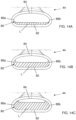
- the liquid L leaving the outlet extremity 80 does not touch the central part, or most of the central part, of the upper edge 84 of the outlet extremity 80 (as better visible, for example, in Figures from 14A to 14C).
- turbulences of the liquid leaving the outlet extremity 80 are reduced compared to known nozzles.
- the obstruction 60 with its cross-sectional area A2, in fact, causes the liquid to distribute over the bent zone 46 of the sprayer portion 44 up to outlet extremity 80.
- the liquid reaching the outlet extremity 80 preferably does not fill completely the corresponding cross-sectional area in any working condition.
- Figure 14A refers to a first working condition wherein the recirculation pump 22 is preferably driven at a low speed and the liquid in the recirculation line 30 is pumped at a corresponding low flow rate.
- the liquid L shows a first course and leaves the same outlet extremity 80 so that it can be sprayed onto the laundry at the near side in front of the washing drum 4 (as indicated with line Lf in Figure 15 ).
- the liquid L leaving the outlet extremity 80 does not touch the upper edge 84. Creation of turbulences is therefore avoided.
- Figure 14B refers to a second working condition wherein the recirculation pump 22 is preferably driven at a medium speed and the liquid in the recirculation line 30 is pumped at corresponding medium flow rate.
- the liquid L shows a second course and leaves the same outlet extremity 80 so that it can be sprayed onto the laundry at the centre of the washing drum 4 (as indicated with line Mf in Figure 15 ).
- the liquid L leaving the outlet extremity 80 does not touch the central part of the upper edge 84. Creation of turbulences is therefore avoided.
- Figure 14C refers to a third working condition wherein the recirculation pump 22 is preferably driven at a high speed and the liquid in the recirculation line 30 is pumped at corresponding high flow rate.
- the liquid L shows a third course and leaves the same outlet extremity 80 so that it can be sprayed onto the laundry at the far side of the washing drum 4 (as indicated with line Hf in Figure 15 ).
- the liquid L leaving the outlet extremity 80 does not touch the central part of the upper edge 84. Creation of turbulences is therefore avoided.
- the proposed solution advantageously enables the control of the flow direction of the liquid over the laundry as a function of the flow rate assuring the optimal liquid distribution over the laundry in each working condition.
- the recirculation pump 22 is a fixed speed pump, then, it is in any case assured that creation of turbulences is avoided or strongly limited when the liquid L leaves the outlet extremity 80, irrespective of the working speed set for the recirculation pump.
- manufacturers can take advantage of this aspect by producing a unique type nozzle that can be mounted on different types of laundry washing machines using recirculation pumps working at different fixed speed. Manufacturing costs are thus reduced. Irrespective of the recirculation pump mounted on the laundry washing machine, therefore, the nozzle assures that creation of turbulences is avoided or strongly limited.
- the tubular portion 42 is integrally made with the sprayer portion 44.
- the nozzle may be realized with different parts structured for being reciprocally coupled.
- the nozzle or parts realizing the same are made of a rigid material, preferably a rigid plastic material, more preferably made of POM (Polyoxymethyleneplast) .
- bellows 107 comprises a housing 107a apt to completely receive the nozzle 40 therein.
- the housing 107a is preferably shaped to totally match the outer surface of the nozzle 40.
- Figure 16B shows the nozzle 40 before it is assembled in the housing 107a of the bellows 107.
- the present invention allows all the set objects to be achieved.
- it makes it possible to provide a laundry washing machine having a liquid supply system which guarantees an optimal liquid distribution over the laundry, also at different flow rate conditions, compared to known systems.
- the recirculation line 30 above described is an example of a liquid supply line in a laundry washing machine which advantageously implements the invention.
- a liquid supply line may be any other supply line which supplies liquid into the washing tub/drum and provided with a nozzle at its extremity.
- the supply pipe 18 connecting the treating agents dispenser 14 to the washing tub 3 provided at its end with a nozzle can be considered a liquid supply line according to the invention.
Description
- The present invention concerns the field of laundry washing techniques.
- In particular, the invention relates to a liquid/water supply system in laundry washing machines that is capable of efficiently supplying liquid/water to laundry received therein.
- Nowadays the use of laundry washing machines, both "simple" laundry washing machines (i.e. laundry washing machines which can only wash and rinse laundry) and laundry washing-drying machines (i.e. laundry washing machines which can also dry laundry), is widespread.
- In the present description, therefore, the term "laundry washing machine" will refer to both a simple laundry washing machine and a laundry washing-drying machine.
- Laundry washing machines generally comprise an external casing, or cabinet, provided with a washing tub which contains a rotatable perforated washing drum where the laundry is placed. A loading/unloading door ensures access to the washing drum.
- Laundry washing machines typically comprise a water supply unit and a treating agents dispenser, preferably having a drawer with compartments, for the introduction of water and washing/rinsing products (i.e. detergent, softener, rinse conditioner, etc.) into the washing tub. A pipe preferably connects the dispenser to the washing tub.
- In known preferred embodiments, the water which reaches the washing tub can selectively contain one of the products contained in the compartments of the dispenser, or such water can be clean and in such a case it may preferably reach the washing tub bypassing the compartments of the dispenser.
- In alternative known embodiments, a further separate water supply pipe bypassing the dispenser can be provided, which supplies directly clean water into the washing tub.
- Known laundry washing machines are also typically provided with recirculation circuits that drain liquid from the bottom region of the washing tub and re-admitt it into another region of the washing tub. Preferably, liquid is re-admitted at an upper region of the washing tub and the recirculation circuit is typically provided with a terminal nozzle opportunely arranged so that the recirculated liquid is sprayed over the laundry.
- The recirculation circuit is typically provided with a recirculation pump which is opportunely activated to recirculate liquid when necessary during the washing cycle enhancing distribution of the liquid over the laundry through the nozzle.
- Numerous efforts and attempts have been made by laundry washing machine manufacturers to find solutions that optimise the distribution of water over the laundry and different shapes for the terminal nozzle have been proposed.
-
US2014109620A1 discloses a nozzle, or water supply device, having an upper vertical hollow pipe connectable to a water supplying line and a lower horizontal sprayer. Horizontal sprayer has a trapezoidal shape and wash water is sprayed through the frontal opening of the sprayer, having a slit shape, over the laundry.EP1505191A1 discloses a washing machine provided with a nozzle for spraying washing water into a drum at a broadened angle. The nozzle has a vertical waterspraying angle in the range of 30 DEG to 40 DEG . -
US2016115635A1 discloses a washing machine having an inner drum, an outer tub and circulation flowpath that is configured to circulate water. The washing machine includes a first nozzle that is configured to jet water supplied from the circulation flowpath to the inner drum. The washing machine further includes an adjustable pump that is configured to pump water through the circulation flowpath to the first nozzle, the adjustable pump being configured to adjust flow of water to the first nozzle. -
EP2602381A2 discloses a drum washing machine capable of receiving water from an external water-supply source and directly spraying the received water to the laundry inside the drum through a nozzle unit. The nozzle unit is a variabletype nozzle unit that can adjust a water jetting type of the nozzle unit according to a displacement of a linear actuator that is installed inside the nozzle unit and moves back and forth. - However, the nozzles of the known art pose some drawbacks.
- A drawback of nozzles of the known art is the decreasing of the spraying efficiency when the flow rate of the water through the supplying line varies.
- The nozzles and their shapes are typically designed to work properly at a predetermined, or substantially predetermined, flow rate according to the working pump speed. In particular, the water follows a desired path from the sprayer opening to the laundry in order to be uniformly distributed over the laundry.
- If the pump speed varies, nevertheless, the uniform distribution is not guaranteed. In particular, if the pump speed increases turbulences are generated at the sprayer opening thus variating the desired optimal water path.
- The object of the present invention is therefore to overcome the drawbacks posed by the known techniques.
- An object of the present invention is therefore to propose a liquid supply system which guarantees the desired liquid distribution over the laundry at different flow rate conditions.
- Another object of the present invention is to propose a liquid supply system enabling the control of the flow direction of the liquid over the laundry as a function of the flow rate assuring the optimal liquid distribution over the laundry in each working condition.
- Applicant has found that by providing a laundry washing machine comprising a washing tub external to a washing drum and a liquid supply line for supplying liquid into said washing tub/drum through a nozzle having an outlet extremity and by providing said nozzle with an obstruction, it is possible to reach the mentioned objects.
- In a first aspect thereof the present invention relates, therefore, to a laundry washing machine comprising:
- a cabinet supporting a washing tub external to a washing drum adapted to receive laundry;
- a liquid supply line for supplying liquid into said washing tub/drum through an outlet extremity, said liquid supply line being provided at an end thereof with a nozzle comprising said outlet extremity, said nozzle comprising a tubular portion extending along an axis and a sprayer portion comprising said outlet extremity and hydraulically communicating with said tubular portion, wherein said sprayer portion comprises a bent zone which is apt to change the direction of a liquid flowing through said tubular portion towards said outlet extremity, wherein said nozzle comprises an obstruction arranged upstream of said bent zone so that the cross-sectional area of said nozzle first decreases and then increases while proceeding from said tubular portion towards said outlet extremity.
- Preferably, the cross-sectional area is the area of the nozzle, where the liquid may flow, in a plane perpendicular to said axis.
- According to the invention, the cross-sectional area first monotonically decreases and then monotonically increases while proceeding from the tubular portion towards the outlet extremity.
- In a preferred embodiment of the invention, the cross-sectional area comprises a smaller area wherein the smaller area is defined at a single point along the axis. Preferably, the tubular portion comprises a portion that extends rectilinearly along the axis.
- According to a preferred embodiment of the invention, the nozzle is arranged so that the axis of the tubular portion and a vertical axis, with the laundry washing machine installed on a horizontal floor, form an angle lower than 30° therebetween, preferably form an angle lower than 10° therebetween, more preferably form an angle equal to 7° therebetween.
- In a preferred embodiment of the invention, the bent zone is apt to change a first direction of a liquid flowing in the tubular portion into a second direction of the liquid towards the outlet extremity.
- According to a preferred embodiment of the invention, the first and second directions are inclined one to the other with an angle comprised therebetween less than 135°, preferably an angle comprised therebetween equal to 90°. Preferably, the sprayer portion has a width that expands towards the outlet extremity, more preferably has a trapezoidal shape.
- According to a preferred embodiment of the invention, the outlet extremity comprises a lower edge and an upper edge connected therebetween at opposite ends.
- In a preferred embodiment of the invention, the distance between the upper edge and the lower edge decreases by proceeding from the center of the outlet extremity towards the opposite ends, the distance being measured in a direction parallel to the axis.
- Preferably, the lower edge is rectilinear and/or the upper edge is arcuate.
- According to a preferred embodiment of the invention, the liquid supply line comprises a recirculation system for draining liquid from the bottom of the washing tub and to re-admit such liquid into a first region of the washing tub/drum, the recirculation system comprising a recirculation pump and a recirculation duct connected to the nozzle.
- In a preferred embodiment of the invention, the recirculation pump is a variable-speed pump.
- Preferably, the recirculation pump comprises an inlet connected to the bottom of the washing tub and an outlet connected to the recirculation duct.
- According to a preferred embodiment of the invention, the liquid supply line is configured to supply liquid into the washing tub/drum at different flow rates.
- In a preferred embodiment of the invention, the nozzle is arranged at a bellows interposed between the cabinet and the washing tub.
- Preferably, the bellows comprises a housing apt to receive the nozzle.
- Further characteristics and advantages of the present invention will be highlighted in greater detail in the following detailed description of some of its preferred embodiments, provided with reference to the enclosed drawings. In the drawings, corresponding characteristics and/or components are identified by the same reference numbers. In particular:
-
Figure 1 shows a perspective view of a laundry washing machine according to a preferred embodiment of the invention; -
Figure 2 shows a schematic view of the laundry washing machine ofFigure 1 ; -
Figure 3 shows an enlarged view of a detail ofFigure 1 with some components removed therefrom; -
Figure 4 shows the detail ofFigure 3 from another point of view; -
Figure 5 shows an exploded view ofFigure 3 ; -
Figure 6 is a plan sectional view taken along line VI°-VI° ofFigure 3 ; -
Figure 7 is a plan frontal view of an element ofFigure 5 ; -
Figure 8 is a plan upper view of the element ofFigure 7 ; -
Figure 9 is a plan sectional view taken along line IX°-IX° ofFigure 7 ; -
Figure 10 is a plan sectional view taken along line X°-X° ofFigure 7 ; -
Figure 11 is a plan sectional view taken along line XI°-XI° ofFigure 7 ; -
Figure 12 is a plan sectional view taken along line XII°-XII° ofFigure 7 ; -
Figure 13 is a plan sectional view taken along line XIII°-XIII° ofFigure 8 ; -
Figures 14A, 14B and 14C show a detail ofFigure 7 in different working conditions; -
Figure 15 shows a side schematic view of the laundry washing machine ofFigure 1 ; -
Figure 16A shows a further embodiment ofFigure 6 ; -
Figure 16B shows the elements ofFigure 16A before assembling. - The present invention has proved to be particularly advantageous when applied to laundry washing machines, as described below. It should in any case be underlined that the present invention is not limited to laundry washing machines. On the contrary, the present invention can be conveniently applied to laundry washing-drying machines (i.e. laundry washing machines which can also dry laundry).
- With reference to
Figures 1 and2 , a preferred embodiment of alaundry washing machine 1 according to the invention is described. - The
laundry washing machine 1 comprises an external casing orcabinet 2, awashing tub 3, awashing drum 4 received in thewashing tub 3, preferably aperforated washing drum 4, where the laundry to be treated can be loaded. - The
washing tub 3 and thewashing drum 4 both preferably have a substantially cylindrical shape. - The
washing tub 3 is preferably connected to thecabinet 2 by means of anelastic bellows 7, or gasket. - The
cabinet 2 is provided with a loading/unloading door 8 which allows access to thewashing drum 4. - The
washing drum 4 is advantageously rotated by an electric motor, not illustrated, which preferably transmits the rotating motion to theshaft 4a of thewashing drum 4, advantageously by means of a belt/pulley system. In a different embodiment of the invention, the motor can be directly associated with theshaft 4a of thewashing drum 4. - The
washing drum 4 is advantageously provided with holes which allow the liquid flowing therethrough. Said holes are typically and preferably homogeneously distributed on the cylindrical side wall of thewashing drum 4. Thebottom region 3a of thewashing tub 3 preferably comprises aseat 15, or sump, suitable for receiving aheating device 10. Theheating device 10, when activated, heats the liquid inside thesump 15. - In different embodiments, nevertheless, the bottom region of the washing tub may be configured differently. For example, the bottom region of the washing tub may not comprise a seat for the heating device. The heating device may be advantageously placed in the annular gap between the washing tub and the washing drum.
- Preferably,
laundry washing machine 1 comprises adevice 19 suited to sense (or detect) the liquid level inside thewashing tub 3. - The
sensor device 19 preferably comprises a pressure sensor which senses the pressure in thewashing tub 3. From the values sensed by thesensor device 19 it is possible to determine the liquid level of the liquid inside thewashing tub 3. In another embodiment, not illustrated, laundry washing machine may preferably comprise (in addition to or as a replacement of the pressure sensor) a level sensor (for example mechanical, electro-mechanical, optical, etc.) adapted to sense (or detect) the liquid level inside thewashing tub 3. - A
water supply circuit 5 is preferably arranged in the upper part of thelaundry washing machine 1 and is suited to supply water into the washing tub/drum water supply circuit 5 preferably comprises a controlledsupply valve 5a which is properly controlled, opened and closed, during the washing cycle. The water supply circuit of a laundry washing machine is well known in the art, and therefore it will not be described in detail. Thelaundry washing machine 1 advantageously comprises a treatingagents dispenser 14 to supply one or more treating agents into the washing tub/drum agents dispenser 14 comprises a removable drawer 6 (Figure 1 ) provided with various compartments suited to be filled with treating agents. - In a preferred embodiment, not illustrated, the treating agents dispenser may comprise a pump suitable to convey one or more of said agents from the dispenser to the washing tub/drum.
- In the preferred embodiment here illustrated, the water is supplied into the washing tub/
drum water supply circuit 5 by making it flow through the treatingagents dispenser 14 and then through asupply pipe 18. Thesupply pipe 18 hydraulically connects the treatingagents dispenser 14 to thewashing tub 3. - In an alternative embodiment of the invention, a further separate water supply pipe can be provided, which supplies exclusively clean water into the washing tub/drum from the external water supply line.
- In further preferred embodiments, not illustrated herein, a water softening device may preferably be arranged/interposed between the external water supply line and the treating agents dispenser so as to be crossed by the fresh water flowing from the external water supply line. The water softening device, as known, is structured for reducing the hardness degree of the fresh water drawn from the external water supply line E and conveyed to the treating agents dispenser.
- In a different embodiment, the water softening device may be arranged/interposed between the external water supply line and the washing tub, so as to be crossed by the fresh water flowing from the external water supply line and conveying it directly to the washing tub/drum.
-
Laundry washing machine 1 preferably comprises awater outlet circuit 25 suitable for withdrawing liquid from thebottom region 3a of thewashing tub 3. Thewater outlet circuit 25 preferably comprises amain pipe 17, a drainingpump 27 and anoutlet pipe 28 ending outside thecabinet 2. - The
water outlet circuit 25 preferably further comprises afiltering device 12 arranged between themain pipe 17 and the drainingpump 27. Thefiltering device 12 is adapted to retain all the undesirable bodies (for example buttons that have come off the laundry, coins erroneously introduced into the laundry washing machine, etc.). Thefiltering device 12 can preferably be removed, and then cleaned, through agate 13 placed advantageously on the front wall of thecabinet 2 of thelaundry washing machine 1, as illustrated inFigure 1 . - The
main pipe 17 connects thebottom region 3a of thewashing tub 3 to thefiltering device 12. - In a further embodiment, not illustrated, the
filtering device 12 may be provided directly in thewashing tub 3, preferably obtained in a single piece construction with the latter. In this case, thefiltering device 12 is fluidly connected to the outlet of thewashing tub 3, in such a way that water and washing liquid drained from thewashing tub 3 enters thefiltering device 12. - Activation of the draining
pump 27 drains the liquid, i.e. dirty water or water mixed with washing and/or rinsing products, from thewashing tub 3 to the outside. - The
laundry washing machine 1 then preferably comprises arecirculation line 30 which is adapted to drain liquid from thebottom region 3a of thewashing tub 3 and to re-admit such a liquid into afirst region 3b of the washing tub/drum - Preferably, the
first region 3b of the washing tub/drum upper region 3b of the washing tub/drum upper region 3b of the washing tub/drum washing drum 4. This action is preferably carried out at the beginning of a washing cycle when the laundry needs to be completely soaked. Furthermore, this action is preferably carried out during rinsing phases at the beginning of the washing cycle or during rinsing phases in successive steps of the washing cycle. - The
recirculation line 30 preferably comprises arecirculation duct 33 terminating at saidfirst region 3b. Preferably therecirculation duct 33 terminates at thebellows 7, as better illustrated inFigures 3 and6 . Therecirculation duct 33 is preferably provided with aterminal nozzle 40 having anoutlet extremity 80. - The
recirculation line 30, then, preferably comprises arecirculation pump 22 comprising aninlet 24 connected to the bottom 3a of thewashing tub 3 and anoutlet 26 for conveying liquid to therecirculation duct 33. -
Inlet 24 of therecirculation pump 22 is preferably connected to the bottom 3a of thewashing tub 3 through asuction pipe 32 preferably connected to thefiltering device 12. - In the preferred embodiment here illustrated and described there are two pumps, a draining
pump 27 and arecirculation pump 22, as described above. - In a further preferred embodiment, not illustrated, only one pump may be provided and a controlled valve may be arranged downstream of the pump for selectively conveying liquid to a drain duct to the outside or to a recirculation duct to the washing tub.
- According to a preferred embodiment of the invention, the
recirculation pump 22 is a variable-speed pump, i.e. it can be driven at different speeds. - In a further preferred embodiment of the invention, the recirculation pump may be a fixed speed pump, i.e. it can be driven at one prefixed speed.
- In case the
recirculation pump 22 is a variable-speed pump, the liquid in therecirculation line 30 may be pumped at different flow rates, as better described later, and thus defining corresponding different working conditions. - In case the
recirculation pump 22 is a fixed speed pump, the liquid in therecirculation line 30 is pumped at a corresponding fixed flow rate. - According to an aspect of the invention, the
nozzle 40 comprises atubular portion 42 extending along a first axis X and asprayer portion 44 comprising theoutlet extremity 80, as illustrated inFigures 7 and9 . Thesprayer portion 44 hydraulically communicates with thetubular portion 42. Thesprayer portion 44 then comprises abent zone 46 which is apt to change the direction of a liquid, not shown, flowing through thetubular portion 42 towards theoutlet extremity 80. - The
tubular portion 42 preferably comprises a portion that extends rectilinearly along the first axis X, for example a cylindrical tubular portion as illustrated herein having a rectilinear axis X. - In different embodiments, nevertheless, the tubular portion may also be curved and therefore extending along a curvilinear axis.
- The
tubular portion 42, then, preferably comprises a cross section of circular shape, as illustrated herein. - In different embodiments, nevertheless, the cross section of the tubular portion may have different shapes, for example any elliptical shape, any curvilinear closed shape, any polygonal closed shape, or a combination thereof.
- The
tubular portion 42 is apt to be fluidly connected to anend 33a of therecirculation duct 33, as illustrated in particular inFigures 5 and 6 . - Preferably, the
tubular portion 42 and theend 33a of therecirculation duct 33 are fluidly connected each other through thebellows 7. - The
bellows 7 comprises ahousing 7a apt to receive from above theend 33a of therecirculation duct 33 and to receive from below thenozzle 40. - The
housing 7a is preferably shaped to completely receive theend 33a of therecirculation duct 33, to receive thetubular portion 42 of thenozzle 40 and preferably part of thesprayer portion 44 of thenozzle 40. - The
nozzle 40 is therefore preferably in part arranged externally of thesame bellows 7 and protrudes therefrom. - According to an aspect of the invention, the
nozzle 40 is arranged in a vertical position, or in a vertical substantially position, with respect to thewashing tub 3, considering thelaundry washing machine 1 installed on a horizontal floor. Preferably, thenozzle 40 is arranged so that the first axis X and the vertical axis V form an angle of 7° therebetween, with thelaundry washing machine 1 installed on a horizontal floor. - More preferably the
nozzle 40 is arranged at thebellows 7 between thewashing tub 3 and thecabinet 2 and opportunely oriented such that the liquid flowing outside theoutlet extremity 80 is directed toward the inside of thewashing drum 4, as better described in the following. - In different embodiments the position of the nozzle could be different, for example more inclined with respect the vertical axis V and preferably arranged so that the first axis X and the vertical axis V form an angle lower than 30° therebetween, more preferably an angle lower than 10° therebetween.
- As illustrated in
Figure 9 , the first direction D1 of a liquid flowing in thetubular portion 42 is changed into a different second direction D2 towards theoutlet extremity 80 by thebent zone 46. - In the preferred embodiment illustrated herewith, the
bent zone 46 is opportunely shaped so that the said two directions D1, D2 are preferably perpendicular, more preferably the first direction D1 is vertical and the second direction D2 is horizontal. - In different embodiments, nevertheless, the bent zone may be opportunely shaped so that the said directions are inclined one to the other with an angle comprised therebetween preferably less than 135°.
- According to the invention, the
nozzle 40 comprises anobstruction 60 arranged upstream of thebent zone 46 so that the cross-sectional area of thenozzle 40 first decreases and then increases while proceeding from thetubular portion 42 towards theoutlet extremity 80. - The cross-sectional area is the area of the
nozzle 40, where the liquid may flow, in a plane perpendicular to the first axis X. - It is underlined that in the present application the term "upstream" is referred to the flowing direction of the liquid inside the
nozzle 40 during the standard functioning of thelaundry washing machine 1 when therecirculation pump 22 is activated; saying thatobstruction 60 is arranged upstream of thebent zone 46 means that in the standard functioning of thelaundry washing machine 1 when therecirculation pump 22 is activated the liquid firstly circulates inside theobstruction 60 and then passes through thebent zone 46. - The term "downstream", when used, will have the opposite meaning of the term "upstream" as defined above.
- This advantageous feature may be appreciated in particular in
Figure 13 or by comparingFigures 10 to 12 . Theobstruction 60 causes the cross-sectional area of thenozzle 40 first to decrease, i.e. from the first area A1 depicted inFigure 10 to a second smaller area A2 depicted inFigure 11 , and then to increases, i.e. from the second smaller area A2 depicted inFigure 11 to a third larger area A3 depicted inFigure 12 . Preferably, theobstruction 60 is arranged in the border zone between thetubular portion 42 and thesprayer portion 44. - The cross-sectional area of the
nozzle 40 monotonically decreases from the first area A1 to the second smaller area A2 and monotonically increases from the second smaller area A2 to the third larger area A3. - Preferably, the second smaller area A2 is defined at a single point, or at a substantially single point, along the first axis X of the tubular portion 42 (point T depicted in
Figure 13 ). - Preferably, the cross-sectional area A2 at the
obstruction 60 is comprised between 50% and 90% of the cross-sectional area A1 at thetubular portion 42, more preferably equal to 70%. - The
sprayer portion 44 preferably has a width that expands towards theoutlet extremity 80 and more preferably shows a trapezoidal shape. - The
outlet extremity 80 preferably comprises alower edge 82 and anupper edge 84 connected therebetween (seeFigure 7 ). - The
lower edge 82 is preferably rectilinear. Theupper edge 84 is preferably arcuate. Thelower edge 82 and theupper edge 84 are preferably connected atopposite ends - Preferably, the distance D between the
upper edge 84 and thelower edge 82 decreases by proceeding from the center C of theoutlet extremity 80 towards the opposite ends 86a, 86b, as shown inFigure 7 . - Advantageously, as better described below, the liquid L leaving the
outlet extremity 80 does not touch the central part, or most of the central part, of theupper edge 84 of the outlet extremity 80 (as better visible, for example, in Figures from 14A to 14C). - Advantageously, turbulences of the liquid leaving the
outlet extremity 80 are reduced compared to known nozzles. - More advantageously, turbulences of the liquid leaving the
outlet extremity 80 are reduced compared to known nozzles in any working condition. - These advantageous aspects are achieved by the presence of the
obstruction 60. Theobstruction 60 with its cross-sectional area A2, in fact, causes the liquid to distribute over thebent zone 46 of thesprayer portion 44 up tooutlet extremity 80. - The liquid reaching the
outlet extremity 80 preferably does not fill completely the corresponding cross-sectional area in any working condition. - Functioning of the
laundry washing machine 1 in different working conditions is explained with some examples as shown inFigures 14A, 14B, 14C and15 . -
Figure 14A refers to a first working condition wherein therecirculation pump 22 is preferably driven at a low speed and the liquid in therecirculation line 30 is pumped at a corresponding low flow rate. At theoutlet extremity 80 the liquid L shows a first course and leaves thesame outlet extremity 80 so that it can be sprayed onto the laundry at the near side in front of the washing drum 4 (as indicated with line Lf inFigure 15 ). - Advantageously, the liquid L leaving the
outlet extremity 80 does not touch theupper edge 84. Creation of turbulences is therefore avoided. -
Figure 14B refers to a second working condition wherein therecirculation pump 22 is preferably driven at a medium speed and the liquid in therecirculation line 30 is pumped at corresponding medium flow rate. At theoutlet extremity 80 the liquid L shows a second course and leaves thesame outlet extremity 80 so that it can be sprayed onto the laundry at the centre of the washing drum 4 (as indicated with line Mf inFigure 15 ). - Advantageously, again, the liquid L leaving the
outlet extremity 80 does not touch the central part of theupper edge 84. Creation of turbulences is therefore avoided. -
Figure 14C refers to a third working condition wherein therecirculation pump 22 is preferably driven at a high speed and the liquid in therecirculation line 30 is pumped at corresponding high flow rate. At theoutlet extremity 80 the liquid L shows a third course and leaves thesame outlet extremity 80 so that it can be sprayed onto the laundry at the far side of the washing drum 4 (as indicated with line Hf inFigure 15 ). - Advantageously, again, the liquid L leaving the
outlet extremity 80 does not touch the central part of theupper edge 84. Creation of turbulences is therefore avoided. - From the above, it follows that the proposed solution advantageously enables the control of the flow direction of the liquid over the laundry as a function of the flow rate assuring the optimal liquid distribution over the laundry in each working condition.
- In case the
recirculation pump 22 is a fixed speed pump, then, it is in any case assured that creation of turbulences is avoided or strongly limited when the liquid L leaves theoutlet extremity 80, irrespective of the working speed set for the recirculation pump. - For example, manufacturers can take advantage of this aspect by producing a unique type nozzle that can be mounted on different types of laundry washing machines using recirculation pumps working at different fixed speed. Manufacturing costs are thus reduced. Irrespective of the recirculation pump mounted on the laundry washing machine, therefore, the nozzle assures that creation of turbulences is avoided or strongly limited.
- It is clear that in case the
recirculation pump 22 is a fixed speed pump the liquid L is sprayed onto the laundry at a substantially fixed position inside thewashing drum 4. - Preferably, the
tubular portion 42 is integrally made with thesprayer portion 44. In further preferred embodiments of the invention, the nozzle may be realized with different parts structured for being reciprocally coupled. - In a preferred embodiment, the nozzle or parts realizing the same are made of a rigid material, preferably a rigid plastic material, more preferably made of POM (Polyoxymethyleneplast) .
- With reference to
Figures 16A and 16B a further preferred embodiment of the invention is described which differs from the preferred embodiment previously described in that thebellows 107 comprises ahousing 107a apt to completely receive thenozzle 40 therein. - The
housing 107a is preferably shaped to totally match the outer surface of thenozzle 40. - When the
nozzle 40 is received in thehousing 107a of the bellows it does not protrude therefrom. -
Figure 16B shows thenozzle 40 before it is assembled in thehousing 107a of thebellows 107. - It has thus been shown that the present invention allows all the set objects to be achieved. In particular, it makes it possible to provide a laundry washing machine having a liquid supply system which guarantees an optimal liquid distribution over the laundry, also at different flow rate conditions, compared to known systems.
- The
recirculation line 30 above described is an example of a liquid supply line in a laundry washing machine which advantageously implements the invention. - In different preferred embodiment, a liquid supply line may be any other supply line which supplies liquid into the washing tub/drum and provided with a nozzle at its extremity. For example, looking at
Figure 2 , thesupply pipe 18 connecting the treatingagents dispenser 14 to thewashing tub 3 provided at its end with a nozzle can be considered a liquid supply line according to the invention. - While the present invention has been described with reference to the particular embodiments shown in the figures, it should be noted that the present invention is not limited to the specific embodiments illustrated and described herein; on the contrary, further variants of the embodiments described herein fall within the scope of the present invention, which is defined in the claims.
Claims (14)
- A laundry washing machine (1) comprising:- a cabinet (2) supporting a washing tub (3) external to a washing drum (4) adapted to receive laundry;- a liquid supply line (30) for supplying liquid into said washing tub/drum (3, 4) through an outlet extremity (80), said liquid supply line (30) being provided at an end thereof with a nozzle (40) comprising said outlet extremity (80), said nozzle (40) comprising a tubular portion (42) extending along an axis (X) and a sprayer portion (44) comprising said outlet extremity (80) and hydraulically communicating with said tubular portion (42), wherein said sprayer portion (44) comprises a bent zone (46) which is apt to change the direction of a liquid flowing through said tubular portion (42) towards said outlet extremity (80), wherein said nozzle (40) comprises an obstruction (60) arranged upstream of said bent zone (46) so that the cross-sectional area of said nozzle (40) first decreases and then increases while proceeding from said tubular portion (42) towards said outlet extremity (80), characterized in that said cross-sectional area first monotonically decreases and then monotonically increases while proceeding from said tubular portion (42) towards said outlet extremity (80).
- Laundry washing machine (1) according to the preceding claim, characterized in that said cross-sectional area comprises a smaller area wherein said smaller area is defined at a single point (T) along said axis (X).
- Laundry washing machine (1) according to any of the preceding claims, characterized in that said tubular portion (42) comprises a portion that extends rectilinearly along said axis (X).
- Laundry washing machine (1) according to any of the preceding claims, characterized in that said nozzle (40) is arranged so that said axis (X) of said tubular portion (42) and a vertical axis (V), with the laundry washing machine installed on a horizontal floor, form an angle lower than 30° therebetween, preferably form an angle lower than 10° therebetween, more preferably form an angle equal to 7° therebetween.
- Laundry washing machine (1) according to any of the preceding claims, characterized in that said bent zone (46) is apt to change a first direction (D1) of a liquid flowing in said tubular portion (42) into a second direction (D2) of said liquid towards said outlet extremity (80).
- Laundry washing machine (1) according to claim 5, characterized in that said first and second directions (D1, D2) are inclined one to the other with an angle comprised therebetween less than 135°, preferably an angle comprised therebetween equal to 90°.
- Laundry washing machine (1) according to any of the preceding claims, characterized in that said outlet extremity (80) comprises a lower edge (82) and an upper edge (84) connected therebetween at opposite ends (86a, 86b).
- Laundry washing machine (1) according to claim 7, characterized in that the distance (D) between said upper edge (84) and said lower edge (82) decreases by proceeding from the center (C) of said outlet extremity (80) towards said opposite ends (86a, 86b), said distance (D) being measured in a direction parallel to said axis (X).
- Laundry washing machine (1) according to claim 7 or 8, characterized in that said lower edge (82) is rectilinear and/or said upper edge (84) is arcuate.
- Laundry washing machine (1) according to any of the preceding claims, characterized in that said liquid supply line (30) comprises a recirculation system for draining liquid from the bottom (3a) of said washing tub (3) and to re-admit such liquid into a first region (3b) of said washing tub/drum (3, 4), said recirculation system (30) comprising a recirculation pump (22) and a recirculation duct (33) connected to said nozzle (40).
- Laundry washing machine (1) according to claim 10, characterized in that said recirculation pump (22) is a variable-speed pump.
- Laundry washing machine (1) according to any of the preceding claims, characterized in that said liquid supply line (30) is configured to supply liquid into said washing tub/drum (3, 4) at different flow rates.
- Laundry washing machine (1) according to any of the preceding claims, characterized in that said nozzle (40) is arranged at a bellows (7; 107) interposed between said cabinet (2) and said washing tub (3).
- Laundry washing machine (1) according to claim 13, characterized in that said bellows (7; 107) comprises a housing (7a; 107a) apt to receive said nozzle (40).
Priority Applications (1)
| Application Number | Priority Date | Filing Date | Title |
|---|---|---|---|
| PL18707026.3T PL3755835T3 (en) | 2018-02-22 | 2018-02-22 | Laundry washing machine equipped with a liquid supply line |
Applications Claiming Priority (1)
| Application Number | Priority Date | Filing Date | Title |
|---|---|---|---|
| PCT/EP2018/054395 WO2019161898A1 (en) | 2018-02-22 | 2018-02-22 | Laundry washing machine equipped with a liquid supply line |
Publications (2)
| Publication Number | Publication Date |
|---|---|
| EP3755835A1 EP3755835A1 (en) | 2020-12-30 |
| EP3755835B1 true EP3755835B1 (en) | 2023-08-23 |
Family
ID=61274270
Family Applications (1)
| Application Number | Title | Priority Date | Filing Date |
|---|---|---|---|
| EP18707026.3A Active EP3755835B1 (en) | 2018-02-22 | 2018-02-22 | Laundry washing machine equipped with a liquid supply line |
Country Status (6)
| Country | Link |
|---|---|
| US (1) | US11408115B2 (en) |
| EP (1) | EP3755835B1 (en) |
| CN (1) | CN111727284B (en) |
| AU (1) | AU2018410489A1 (en) |
| PL (1) | PL3755835T3 (en) |
| WO (1) | WO2019161898A1 (en) |
Families Citing this family (8)
| Publication number | Priority date | Publication date | Assignee | Title |
|---|---|---|---|---|
| KR102573125B1 (en) * | 2017-12-28 | 2023-08-30 | 엘지전자 주식회사 | Washing machine |
| IT201900016712A1 (en) * | 2019-09-19 | 2021-03-19 | Candy Spa | LAUNDRY MACHINE |
| KR20210072496A (en) * | 2019-12-09 | 2021-06-17 | 삼성전자주식회사 | Diaphragm assembly and washing machine having the same |
| US11466393B2 (en) * | 2020-03-06 | 2022-10-11 | Whirlpool Corporation | Spray system for an appliance having a flexible spray membrane having a separable seam |
| US20210317607A1 (en) * | 2020-04-08 | 2021-10-14 | Haier Us Appliance Solutions, Inc. | Additive dispensing for washing machine appliances |
| DE102020206472A1 (en) * | 2020-05-25 | 2021-11-25 | BSH Hausgeräte GmbH | LAUNDRY MACHINE WITH A NOZZLE FOR INSERTING A JET OF LIQUID |
| US11725331B2 (en) * | 2020-11-20 | 2023-08-15 | Whirlpool Corporation | Water recirculation assembly for a laundry appliance |
| CN114197141A (en) * | 2021-12-23 | 2022-03-18 | 珠海格力电器股份有限公司 | Washing machine and spray header thereof |
Family Cites Families (36)
| Publication number | Priority date | Publication date | Assignee | Title |
|---|---|---|---|---|
| DE4330079C2 (en) | 1993-09-06 | 2000-05-11 | Bsh Bosch Siemens Hausgeraete | Front loading drum washing machine |
| US6189170B1 (en) | 1999-08-12 | 2001-02-20 | Ronald E. Sherwood | Area rug cleaning method |
| JP2004057821A (en) | 2002-07-30 | 2004-02-26 | Lg Electron Inc | Washing machine |
| KR100688160B1 (en) * | 2003-08-07 | 2007-03-02 | 엘지전자 주식회사 | Front loading type drum washing machine |
| US7406842B2 (en) | 2003-08-13 | 2008-08-05 | Lg Electronics Inc. | Washing machine |
| ATE435325T1 (en) | 2004-05-25 | 2009-07-15 | Electrolux Home Prod Corp | WASHING MACHINE WITH WATER DISPENSING FACILITIES |
| US8567219B2 (en) * | 2007-11-01 | 2013-10-29 | Lg Electronics Inc. | Washing machine |
| KR20090107223A (en) | 2008-04-08 | 2009-10-13 | 엘지전자 주식회사 | Washing Machine |
| JP4877300B2 (en) | 2008-07-09 | 2012-02-15 | パナソニック株式会社 | Drum washing machine |
| JP2010046125A (en) | 2008-08-19 | 2010-03-04 | Toshiba Corp | Washing machine |
| KR101590371B1 (en) | 2009-02-16 | 2016-02-02 | 엘지전자 주식회사 | Washing machine and washing method |
| AU2010201327B2 (en) | 2009-04-03 | 2011-11-03 | Lg Electronics Inc. | Washing machine |
| KR101635873B1 (en) | 2009-09-04 | 2016-07-20 | 엘지전자 주식회사 | Laundry machine |
| US8776297B2 (en) | 2009-10-13 | 2014-07-15 | Lg Electronics Inc. | Laundry treating apparatus and method |
| WO2011053091A2 (en) | 2009-11-02 | 2011-05-05 | Lg Electronics Inc. | Washing machine |
| CN103547724B (en) | 2011-04-14 | 2016-05-04 | Lg电子株式会社 | Washing methods |
| CN103687987B (en) * | 2011-07-18 | 2016-06-29 | Lg电子株式会社 | The washings supply method of washing machine and washing machine |
| JP5873968B2 (en) | 2011-09-05 | 2016-03-01 | パナソニックIpマネジメント株式会社 | Washing machine |
| EP2728057A4 (en) | 2011-11-02 | 2015-01-21 | Dongbu Daewoo Electronics Corp | Water supply apparatus for washing machine |
| KR101820662B1 (en) * | 2011-12-07 | 2018-01-23 | 삼성전자주식회사 | Drum washing machine and washing method thereof |
| WO2013091288A1 (en) * | 2011-12-19 | 2013-06-27 | 海尔集团公司 | Device and method for cleaning observation window and window spacer sealing ring, and washing machine applying the same |
| KR101867819B1 (en) | 2012-02-29 | 2018-06-18 | 엘지전자 주식회사 | Laundry treating machine |
| BR112014003738B1 (en) | 2012-04-06 | 2021-05-25 | Lg Electronics Inc. | methods to control a washing machine and washing machine |
| WO2013151344A2 (en) | 2012-04-06 | 2013-10-10 | Lg Electronics Inc. | Laundry treating machine |
| US8973628B2 (en) | 2012-06-15 | 2015-03-10 | Sally Kimmel | Portable purse strap hook |
| TR201719303T3 (en) | 2013-02-28 | 2019-05-21 | Arcelik As | IMPROVED EFFICIENCY WASHING AND RINSING SYSTEM USED IN A WASHING MACHINE |
| KR20140140435A (en) * | 2013-05-29 | 2014-12-09 | 삼성전자주식회사 | Washing Machine |
| MX358858B (en) | 2013-07-04 | 2018-09-05 | Mabe Sa De Cv | Water inlet sprayer for low pressure (wilp). |
| KR102183472B1 (en) * | 2013-11-07 | 2020-11-27 | 삼성전자주식회사 | Washing Machine |
| KR20150053608A (en) * | 2013-11-08 | 2015-05-18 | 삼성전자주식회사 | Washing Machine |
| US9567703B2 (en) | 2014-10-07 | 2017-02-14 | Haier Us Appliance Solutions, Inc. | Nozzle assembly with multiple spray curvatures and air-lock release geometry |
| KR102196182B1 (en) * | 2014-10-27 | 2020-12-29 | 엘지전자 주식회사 | Washing machine |
| AU2016234984B2 (en) | 2015-10-02 | 2018-11-08 | Lg Electronics Inc. | Washing machine |
| US10202717B2 (en) | 2015-12-02 | 2019-02-12 | Whirlpool Corporation | Fabric enhancer and laundry additive dispensation in laundry appliances |
| EP3933090A1 (en) * | 2017-12-28 | 2022-01-05 | LG Electronics Inc. | Washing machine having a circulation pump |
| KR102573125B1 (en) * | 2017-12-28 | 2023-08-30 | 엘지전자 주식회사 | Washing machine |
-
2018
- 2018-02-22 PL PL18707026.3T patent/PL3755835T3/en unknown
- 2018-02-22 AU AU2018410489A patent/AU2018410489A1/en active Pending
- 2018-02-22 WO PCT/EP2018/054395 patent/WO2019161898A1/en unknown
- 2018-02-22 CN CN201880089672.0A patent/CN111727284B/en active Active
- 2018-02-22 US US16/971,505 patent/US11408115B2/en active Active
- 2018-02-22 EP EP18707026.3A patent/EP3755835B1/en active Active
Also Published As
| Publication number | Publication date |
|---|---|
| AU2018410489A1 (en) | 2020-07-16 |
| WO2019161898A1 (en) | 2019-08-29 |
| EP3755835A1 (en) | 2020-12-30 |
| US20200399817A1 (en) | 2020-12-24 |
| CN111727284A (en) | 2020-09-29 |
| CN111727284B (en) | 2023-09-05 |
| US11408115B2 (en) | 2022-08-09 |
| PL3755835T3 (en) | 2024-02-19 |
Similar Documents
| Publication | Publication Date | Title |
|---|---|---|
| EP3755835B1 (en) | Laundry washing machine equipped with a liquid supply line | |
| JP6522567B2 (en) | Washing machine | |
| US7677062B2 (en) | Washing machine with spraying device | |
| US9051677B2 (en) | Washing machine | |
| CA2527992A1 (en) | Spray fill device and method for using the same | |
| KR20130070275A (en) | Dishwasher and method of controlling the same | |
| US20130081431A1 (en) | Water Recirculation and Drum Rotation Control in a Laundry Washer | |
| EP2890841B1 (en) | Laundry washing machine | |
| JP6092014B2 (en) | Washing machine | |
| EP2658427B1 (en) | A dishwasher wherein ozone wash is applied | |
| KR102541170B1 (en) | Method for controlling water-supply of a dishwasher | |
| US20210047768A1 (en) | Laundry washing machine and method for operating the laundry washing machine | |
| US20210071344A1 (en) | A method of operating a laundry washing machine comprising a recirculation circuit | |
| WO2020088846A1 (en) | A washer/dryer | |
| US11910979B2 (en) | Water-using domestic appliance and method for operating a water-using domestic appliance | |
| KR101689720B1 (en) | Washing machine | |
| US20200370231A1 (en) | Laundry washing machine and method for operating the laundry washing machine | |
| US20230018094A1 (en) | Laundry washing machine | |
| EP2628843B1 (en) | Laundry treatment apparatus with heat exchanger cleaning | |
| KR0128907Y1 (en) | Dishwasher | |
| JP2019084092A (en) | Drum type washing machine |
Legal Events
| Date | Code | Title | Description |
|---|---|---|---|
| STAA | Information on the status of an ep patent application or granted ep patent |
Free format text: STATUS: UNKNOWN |
|
| STAA | Information on the status of an ep patent application or granted ep patent |
Free format text: STATUS: THE INTERNATIONAL PUBLICATION HAS BEEN MADE |
|
| PUAI | Public reference made under article 153(3) epc to a published international application that has entered the european phase |
Free format text: ORIGINAL CODE: 0009012 |
|
| STAA | Information on the status of an ep patent application or granted ep patent |
Free format text: STATUS: REQUEST FOR EXAMINATION WAS MADE |
|
| 17P | Request for examination filed |
Effective date: 20200922 |
|
| AK | Designated contracting states |
Kind code of ref document: A1 Designated state(s): AL AT BE BG CH CY CZ DE DK EE ES FI FR GB GR HR HU IE IS IT LI LT LU LV MC MK MT NL NO PL PT RO RS SE SI SK SM TR |
|
| AX | Request for extension of the european patent |
Extension state: BA ME |
|
| DAV | Request for validation of the european patent (deleted) | ||
| DAX | Request for extension of the european patent (deleted) | ||
| GRAP | Despatch of communication of intention to grant a patent |
Free format text: ORIGINAL CODE: EPIDOSNIGR1 |
|
| STAA | Information on the status of an ep patent application or granted ep patent |
Free format text: STATUS: GRANT OF PATENT IS INTENDED |
|
| INTG | Intention to grant announced |
Effective date: 20230324 |
|
| GRAS | Grant fee paid |
Free format text: ORIGINAL CODE: EPIDOSNIGR3 |
|
| GRAA | (expected) grant |
Free format text: ORIGINAL CODE: 0009210 |
|
| STAA | Information on the status of an ep patent application or granted ep patent |
Free format text: STATUS: THE PATENT HAS BEEN GRANTED |
|
| AK | Designated contracting states |
Kind code of ref document: B1 Designated state(s): AL AT BE BG CH CY CZ DE DK EE ES FI FR GB GR HR HU IE IS IT LI LT LU LV MC MK MT NL NO PL PT RO RS SE SI SK SM TR |
|
| REG | Reference to a national code |
Ref country code: GB Ref legal event code: FG4D |
|
| REG | Reference to a national code |
Ref country code: CH Ref legal event code: EP |
|
| REG | Reference to a national code |
Ref country code: IE Ref legal event code: FG4D |
|
| REG | Reference to a national code |
Ref country code: DE Ref legal event code: R096 Ref document number: 602018055872 Country of ref document: DE |
|
| P01 | Opt-out of the competence of the unified patent court (upc) registered |
Effective date: 20230901 |
|
| REG | Reference to a national code |
Ref country code: LT Ref legal event code: MG9D |
|
| REG | Reference to a national code |
Ref country code: NL Ref legal event code: MP Effective date: 20230823 |
|
| REG | Reference to a national code |
Ref country code: AT Ref legal event code: MK05 Ref document number: 1602710 Country of ref document: AT Kind code of ref document: T Effective date: 20230823 |
|
| PG25 | Lapsed in a contracting state [announced via postgrant information from national office to epo] |
Ref country code: GR Free format text: LAPSE BECAUSE OF FAILURE TO SUBMIT A TRANSLATION OF THE DESCRIPTION OR TO PAY THE FEE WITHIN THE PRESCRIBED TIME-LIMIT Effective date: 20231124 |
|
| PG25 | Lapsed in a contracting state [announced via postgrant information from national office to epo] |
Ref country code: IS Free format text: LAPSE BECAUSE OF FAILURE TO SUBMIT A TRANSLATION OF THE DESCRIPTION OR TO PAY THE FEE WITHIN THE PRESCRIBED TIME-LIMIT Effective date: 20231223 |
|
| PG25 | Lapsed in a contracting state [announced via postgrant information from national office to epo] |
Ref country code: SE Free format text: LAPSE BECAUSE OF FAILURE TO SUBMIT A TRANSLATION OF THE DESCRIPTION OR TO PAY THE FEE WITHIN THE PRESCRIBED TIME-LIMIT Effective date: 20230823 Ref country code: RS Free format text: LAPSE BECAUSE OF FAILURE TO SUBMIT A TRANSLATION OF THE DESCRIPTION OR TO PAY THE FEE WITHIN THE PRESCRIBED TIME-LIMIT Effective date: 20230823 Ref country code: PT Free format text: LAPSE BECAUSE OF FAILURE TO SUBMIT A TRANSLATION OF THE DESCRIPTION OR TO PAY THE FEE WITHIN THE PRESCRIBED TIME-LIMIT Effective date: 20231226 Ref country code: NO Free format text: LAPSE BECAUSE OF FAILURE TO SUBMIT A TRANSLATION OF THE DESCRIPTION OR TO PAY THE FEE WITHIN THE PRESCRIBED TIME-LIMIT Effective date: 20231123 Ref country code: NL Free format text: LAPSE BECAUSE OF FAILURE TO SUBMIT A TRANSLATION OF THE DESCRIPTION OR TO PAY THE FEE WITHIN THE PRESCRIBED TIME-LIMIT Effective date: 20230823 Ref country code: LV Free format text: LAPSE BECAUSE OF FAILURE TO SUBMIT A TRANSLATION OF THE DESCRIPTION OR TO PAY THE FEE WITHIN THE PRESCRIBED TIME-LIMIT Effective date: 20230823 Ref country code: LT Free format text: LAPSE BECAUSE OF FAILURE TO SUBMIT A TRANSLATION OF THE DESCRIPTION OR TO PAY THE FEE WITHIN THE PRESCRIBED TIME-LIMIT Effective date: 20230823 Ref country code: IS Free format text: LAPSE BECAUSE OF FAILURE TO SUBMIT A TRANSLATION OF THE DESCRIPTION OR TO PAY THE FEE WITHIN THE PRESCRIBED TIME-LIMIT Effective date: 20231223 Ref country code: HR Free format text: LAPSE BECAUSE OF FAILURE TO SUBMIT A TRANSLATION OF THE DESCRIPTION OR TO PAY THE FEE WITHIN THE PRESCRIBED TIME-LIMIT Effective date: 20230823 Ref country code: GR Free format text: LAPSE BECAUSE OF FAILURE TO SUBMIT A TRANSLATION OF THE DESCRIPTION OR TO PAY THE FEE WITHIN THE PRESCRIBED TIME-LIMIT Effective date: 20231124 Ref country code: FI Free format text: LAPSE BECAUSE OF FAILURE TO SUBMIT A TRANSLATION OF THE DESCRIPTION OR TO PAY THE FEE WITHIN THE PRESCRIBED TIME-LIMIT Effective date: 20230823 Ref country code: AT Free format text: LAPSE BECAUSE OF FAILURE TO SUBMIT A TRANSLATION OF THE DESCRIPTION OR TO PAY THE FEE WITHIN THE PRESCRIBED TIME-LIMIT Effective date: 20230823 |