EP4001000A1 - Electric vehicle charging method for preventing inrush current and device therefor - Google Patents
Electric vehicle charging method for preventing inrush current and device therefor Download PDFInfo
- Publication number
- EP4001000A1 EP4001000A1 EP21806125.7A EP21806125A EP4001000A1 EP 4001000 A1 EP4001000 A1 EP 4001000A1 EP 21806125 A EP21806125 A EP 21806125A EP 4001000 A1 EP4001000 A1 EP 4001000A1
- Authority
- EP
- European Patent Office
- Prior art keywords
- charging
- electric vehicle
- charged
- current level
- modules
- Prior art date
- Legal status (The legal status is an assumption and is not a legal conclusion. Google has not performed a legal analysis and makes no representation as to the accuracy of the status listed.)
- Pending
Links
- 238000000034 method Methods 0.000 title claims abstract description 42
- 230000007423 decrease Effects 0.000 claims abstract description 56
- 230000003213 activating effect Effects 0.000 claims abstract description 50
- 230000003247 decreasing effect Effects 0.000 claims abstract description 6
- 238000004891 communication Methods 0.000 claims description 27
- 230000004913 activation Effects 0.000 claims description 13
- 238000010586 diagram Methods 0.000 description 8
- 230000006870 function Effects 0.000 description 6
- 239000002699 waste material Substances 0.000 description 6
- 230000002265 prevention Effects 0.000 description 5
- 230000009849 deactivation Effects 0.000 description 4
- 238000012986 modification Methods 0.000 description 4
- 230000004048 modification Effects 0.000 description 4
- 230000008569 process Effects 0.000 description 3
- 230000033228 biological regulation Effects 0.000 description 2
- 230000014509 gene expression Effects 0.000 description 2
- 229910052799 carbon Inorganic materials 0.000 description 1
- 238000013461 design Methods 0.000 description 1
- 238000001514 detection method Methods 0.000 description 1
- 230000006866 deterioration Effects 0.000 description 1
- 230000000694 effects Effects 0.000 description 1
- 230000007613 environmental effect Effects 0.000 description 1
- 230000001747 exhibiting effect Effects 0.000 description 1
- 239000000446 fuel Substances 0.000 description 1
- 238000012423 maintenance Methods 0.000 description 1
- 238000011017 operating method Methods 0.000 description 1
- 230000002093 peripheral effect Effects 0.000 description 1
- 230000009467 reduction Effects 0.000 description 1
- 230000002787 reinforcement Effects 0.000 description 1
- 238000011160 research Methods 0.000 description 1
Images


Classifications
-
- H—ELECTRICITY
- H02—GENERATION; CONVERSION OR DISTRIBUTION OF ELECTRIC POWER
- H02J—CIRCUIT ARRANGEMENTS OR SYSTEMS FOR SUPPLYING OR DISTRIBUTING ELECTRIC POWER; SYSTEMS FOR STORING ELECTRIC ENERGY
- H02J7/00—Circuit arrangements for charging or depolarising batteries or for supplying loads from batteries
- H02J7/0029—Circuit arrangements for charging or depolarising batteries or for supplying loads from batteries with safety or protection devices or circuits
- H02J7/00304—Overcurrent protection
-
- B—PERFORMING OPERATIONS; TRANSPORTING
- B60—VEHICLES IN GENERAL
- B60L—PROPULSION OF ELECTRICALLY-PROPELLED VEHICLES; SUPPLYING ELECTRIC POWER FOR AUXILIARY EQUIPMENT OF ELECTRICALLY-PROPELLED VEHICLES; ELECTRODYNAMIC BRAKE SYSTEMS FOR VEHICLES IN GENERAL; MAGNETIC SUSPENSION OR LEVITATION FOR VEHICLES; MONITORING OPERATING VARIABLES OF ELECTRICALLY-PROPELLED VEHICLES; ELECTRIC SAFETY DEVICES FOR ELECTRICALLY-PROPELLED VEHICLES
- B60L53/00—Methods of charging batteries, specially adapted for electric vehicles; Charging stations or on-board charging equipment therefor; Exchange of energy storage elements in electric vehicles
- B60L53/60—Monitoring or controlling charging stations
- B60L53/67—Controlling two or more charging stations
-
- B—PERFORMING OPERATIONS; TRANSPORTING
- B60—VEHICLES IN GENERAL
- B60L—PROPULSION OF ELECTRICALLY-PROPELLED VEHICLES; SUPPLYING ELECTRIC POWER FOR AUXILIARY EQUIPMENT OF ELECTRICALLY-PROPELLED VEHICLES; ELECTRODYNAMIC BRAKE SYSTEMS FOR VEHICLES IN GENERAL; MAGNETIC SUSPENSION OR LEVITATION FOR VEHICLES; MONITORING OPERATING VARIABLES OF ELECTRICALLY-PROPELLED VEHICLES; ELECTRIC SAFETY DEVICES FOR ELECTRICALLY-PROPELLED VEHICLES
- B60L53/00—Methods of charging batteries, specially adapted for electric vehicles; Charging stations or on-board charging equipment therefor; Exchange of energy storage elements in electric vehicles
- B60L53/60—Monitoring or controlling charging stations
- B60L53/62—Monitoring or controlling charging stations in response to charging parameters, e.g. current, voltage or electrical charge
-
- B—PERFORMING OPERATIONS; TRANSPORTING
- B60—VEHICLES IN GENERAL
- B60L—PROPULSION OF ELECTRICALLY-PROPELLED VEHICLES; SUPPLYING ELECTRIC POWER FOR AUXILIARY EQUIPMENT OF ELECTRICALLY-PROPELLED VEHICLES; ELECTRODYNAMIC BRAKE SYSTEMS FOR VEHICLES IN GENERAL; MAGNETIC SUSPENSION OR LEVITATION FOR VEHICLES; MONITORING OPERATING VARIABLES OF ELECTRICALLY-PROPELLED VEHICLES; ELECTRIC SAFETY DEVICES FOR ELECTRICALLY-PROPELLED VEHICLES
- B60L53/00—Methods of charging batteries, specially adapted for electric vehicles; Charging stations or on-board charging equipment therefor; Exchange of energy storage elements in electric vehicles
- B60L53/30—Constructional details of charging stations
- B60L53/305—Communication interfaces
-
- B—PERFORMING OPERATIONS; TRANSPORTING
- B60—VEHICLES IN GENERAL
- B60L—PROPULSION OF ELECTRICALLY-PROPELLED VEHICLES; SUPPLYING ELECTRIC POWER FOR AUXILIARY EQUIPMENT OF ELECTRICALLY-PROPELLED VEHICLES; ELECTRODYNAMIC BRAKE SYSTEMS FOR VEHICLES IN GENERAL; MAGNETIC SUSPENSION OR LEVITATION FOR VEHICLES; MONITORING OPERATING VARIABLES OF ELECTRICALLY-PROPELLED VEHICLES; ELECTRIC SAFETY DEVICES FOR ELECTRICALLY-PROPELLED VEHICLES
- B60L53/00—Methods of charging batteries, specially adapted for electric vehicles; Charging stations or on-board charging equipment therefor; Exchange of energy storage elements in electric vehicles
- B60L53/60—Monitoring or controlling charging stations
- B60L53/64—Optimising energy costs, e.g. responding to electricity rates
-
- B—PERFORMING OPERATIONS; TRANSPORTING
- B60—VEHICLES IN GENERAL
- B60L—PROPULSION OF ELECTRICALLY-PROPELLED VEHICLES; SUPPLYING ELECTRIC POWER FOR AUXILIARY EQUIPMENT OF ELECTRICALLY-PROPELLED VEHICLES; ELECTRODYNAMIC BRAKE SYSTEMS FOR VEHICLES IN GENERAL; MAGNETIC SUSPENSION OR LEVITATION FOR VEHICLES; MONITORING OPERATING VARIABLES OF ELECTRICALLY-PROPELLED VEHICLES; ELECTRIC SAFETY DEVICES FOR ELECTRICALLY-PROPELLED VEHICLES
- B60L53/00—Methods of charging batteries, specially adapted for electric vehicles; Charging stations or on-board charging equipment therefor; Exchange of energy storage elements in electric vehicles
- B60L53/60—Monitoring or controlling charging stations
- B60L53/66—Data transfer between charging stations and vehicles
-
- H—ELECTRICITY
- H02—GENERATION; CONVERSION OR DISTRIBUTION OF ELECTRIC POWER
- H02J—CIRCUIT ARRANGEMENTS OR SYSTEMS FOR SUPPLYING OR DISTRIBUTING ELECTRIC POWER; SYSTEMS FOR STORING ELECTRIC ENERGY
- H02J7/00—Circuit arrangements for charging or depolarising batteries or for supplying loads from batteries
- H02J7/00032—Circuit arrangements for charging or depolarising batteries or for supplying loads from batteries characterised by data exchange
-
- H—ELECTRICITY
- H02—GENERATION; CONVERSION OR DISTRIBUTION OF ELECTRIC POWER
- H02J—CIRCUIT ARRANGEMENTS OR SYSTEMS FOR SUPPLYING OR DISTRIBUTING ELECTRIC POWER; SYSTEMS FOR STORING ELECTRIC ENERGY
- H02J7/00—Circuit arrangements for charging or depolarising batteries or for supplying loads from batteries
- H02J7/0013—Circuit arrangements for charging or depolarising batteries or for supplying loads from batteries acting upon several batteries simultaneously or sequentially
-
- H—ELECTRICITY
- H02—GENERATION; CONVERSION OR DISTRIBUTION OF ELECTRIC POWER
- H02J—CIRCUIT ARRANGEMENTS OR SYSTEMS FOR SUPPLYING OR DISTRIBUTING ELECTRIC POWER; SYSTEMS FOR STORING ELECTRIC ENERGY
- H02J7/00—Circuit arrangements for charging or depolarising batteries or for supplying loads from batteries
- H02J7/007—Regulation of charging or discharging current or voltage
- H02J7/00712—Regulation of charging or discharging current or voltage the cycle being controlled or terminated in response to electric parameters
- H02J7/00714—Regulation of charging or discharging current or voltage the cycle being controlled or terminated in response to electric parameters in response to battery charging or discharging current
-
- B—PERFORMING OPERATIONS; TRANSPORTING
- B60—VEHICLES IN GENERAL
- B60L—PROPULSION OF ELECTRICALLY-PROPELLED VEHICLES; SUPPLYING ELECTRIC POWER FOR AUXILIARY EQUIPMENT OF ELECTRICALLY-PROPELLED VEHICLES; ELECTRODYNAMIC BRAKE SYSTEMS FOR VEHICLES IN GENERAL; MAGNETIC SUSPENSION OR LEVITATION FOR VEHICLES; MONITORING OPERATING VARIABLES OF ELECTRICALLY-PROPELLED VEHICLES; ELECTRIC SAFETY DEVICES FOR ELECTRICALLY-PROPELLED VEHICLES
- B60L2270/00—Problem solutions or means not otherwise provided for
- B60L2270/20—Inrush current reduction, i.e. avoiding high currents when connecting the battery
-
- B—PERFORMING OPERATIONS; TRANSPORTING
- B60—VEHICLES IN GENERAL
- B60Y—INDEXING SCHEME RELATING TO ASPECTS CROSS-CUTTING VEHICLE TECHNOLOGY
- B60Y2200/00—Type of vehicle
- B60Y2200/90—Vehicles comprising electric prime movers
- B60Y2200/91—Electric vehicles
-
- H—ELECTRICITY
- H01—ELECTRIC ELEMENTS
- H01M—PROCESSES OR MEANS, e.g. BATTERIES, FOR THE DIRECT CONVERSION OF CHEMICAL ENERGY INTO ELECTRICAL ENERGY
- H01M10/00—Secondary cells; Manufacture thereof
- H01M10/42—Methods or arrangements for servicing or maintenance of secondary cells or secondary half-cells
- H01M10/44—Methods for charging or discharging
-
- H—ELECTRICITY
- H02—GENERATION; CONVERSION OR DISTRIBUTION OF ELECTRIC POWER
- H02M—APPARATUS FOR CONVERSION BETWEEN AC AND AC, BETWEEN AC AND DC, OR BETWEEN DC AND DC, AND FOR USE WITH MAINS OR SIMILAR POWER SUPPLY SYSTEMS; CONVERSION OF DC OR AC INPUT POWER INTO SURGE OUTPUT POWER; CONTROL OR REGULATION THEREOF
- H02M1/00—Details of apparatus for conversion
- H02M1/36—Means for starting or stopping converters
-
- Y—GENERAL TAGGING OF NEW TECHNOLOGICAL DEVELOPMENTS; GENERAL TAGGING OF CROSS-SECTIONAL TECHNOLOGIES SPANNING OVER SEVERAL SECTIONS OF THE IPC; TECHNICAL SUBJECTS COVERED BY FORMER USPC CROSS-REFERENCE ART COLLECTIONS [XRACs] AND DIGESTS
- Y02—TECHNOLOGIES OR APPLICATIONS FOR MITIGATION OR ADAPTATION AGAINST CLIMATE CHANGE
- Y02E—REDUCTION OF GREENHOUSE GAS [GHG] EMISSIONS, RELATED TO ENERGY GENERATION, TRANSMISSION OR DISTRIBUTION
- Y02E60/00—Enabling technologies; Technologies with a potential or indirect contribution to GHG emissions mitigation
- Y02E60/10—Energy storage using batteries
-
- Y—GENERAL TAGGING OF NEW TECHNOLOGICAL DEVELOPMENTS; GENERAL TAGGING OF CROSS-SECTIONAL TECHNOLOGIES SPANNING OVER SEVERAL SECTIONS OF THE IPC; TECHNICAL SUBJECTS COVERED BY FORMER USPC CROSS-REFERENCE ART COLLECTIONS [XRACs] AND DIGESTS
- Y02—TECHNOLOGIES OR APPLICATIONS FOR MITIGATION OR ADAPTATION AGAINST CLIMATE CHANGE
- Y02T—CLIMATE CHANGE MITIGATION TECHNOLOGIES RELATED TO TRANSPORTATION
- Y02T10/00—Road transport of goods or passengers
- Y02T10/60—Other road transportation technologies with climate change mitigation effect
- Y02T10/70—Energy storage systems for electromobility, e.g. batteries
-
- Y—GENERAL TAGGING OF NEW TECHNOLOGICAL DEVELOPMENTS; GENERAL TAGGING OF CROSS-SECTIONAL TECHNOLOGIES SPANNING OVER SEVERAL SECTIONS OF THE IPC; TECHNICAL SUBJECTS COVERED BY FORMER USPC CROSS-REFERENCE ART COLLECTIONS [XRACs] AND DIGESTS
- Y02—TECHNOLOGIES OR APPLICATIONS FOR MITIGATION OR ADAPTATION AGAINST CLIMATE CHANGE
- Y02T—CLIMATE CHANGE MITIGATION TECHNOLOGIES RELATED TO TRANSPORTATION
- Y02T10/00—Road transport of goods or passengers
- Y02T10/60—Other road transportation technologies with climate change mitigation effect
- Y02T10/7072—Electromobility specific charging systems or methods for batteries, ultracapacitors, supercapacitors or double-layer capacitors
-
- Y—GENERAL TAGGING OF NEW TECHNOLOGICAL DEVELOPMENTS; GENERAL TAGGING OF CROSS-SECTIONAL TECHNOLOGIES SPANNING OVER SEVERAL SECTIONS OF THE IPC; TECHNICAL SUBJECTS COVERED BY FORMER USPC CROSS-REFERENCE ART COLLECTIONS [XRACs] AND DIGESTS
- Y02—TECHNOLOGIES OR APPLICATIONS FOR MITIGATION OR ADAPTATION AGAINST CLIMATE CHANGE
- Y02T—CLIMATE CHANGE MITIGATION TECHNOLOGIES RELATED TO TRANSPORTATION
- Y02T90/00—Enabling technologies or technologies with a potential or indirect contribution to GHG emissions mitigation
- Y02T90/10—Technologies relating to charging of electric vehicles
- Y02T90/12—Electric charging stations
-
- Y—GENERAL TAGGING OF NEW TECHNOLOGICAL DEVELOPMENTS; GENERAL TAGGING OF CROSS-SECTIONAL TECHNOLOGIES SPANNING OVER SEVERAL SECTIONS OF THE IPC; TECHNICAL SUBJECTS COVERED BY FORMER USPC CROSS-REFERENCE ART COLLECTIONS [XRACs] AND DIGESTS
- Y02—TECHNOLOGIES OR APPLICATIONS FOR MITIGATION OR ADAPTATION AGAINST CLIMATE CHANGE
- Y02T—CLIMATE CHANGE MITIGATION TECHNOLOGIES RELATED TO TRANSPORTATION
- Y02T90/00—Enabling technologies or technologies with a potential or indirect contribution to GHG emissions mitigation
- Y02T90/10—Technologies relating to charging of electric vehicles
- Y02T90/16—Information or communication technologies improving the operation of electric vehicles
- Y02T90/167—Systems integrating technologies related to power network operation and communication or information technologies for supporting the interoperability of electric or hybrid vehicles, i.e. smartgrids as interface for battery charging of electric vehicles [EV] or hybrid vehicles [HEV]
Abstract
Description
- The present disclosure relates to a method for charging an electric vehicle using a plurality of charging modules and a device for the same. Further, the present disclosure relates to a method for preventing an inrush current and a device for the same.
- Recently, the demand for eco-friendly electric vehicles (EVs) has been increased depending on the trend of reinforcement of global environmental regulations and energy cost reduction. As automotive fuel economy and exhaust gas regulations of governments around the world are strengthened, the spread of EVs has been required, and even in Korea, as part of low-carbon green growth, interest and research on green cars (eco-friendly vehicles) have been actively conducted.
- In order to expand the spread of electric vehicles (EVs), it is required to establish a charging infrastructure capable of charging the power of the electric vehicles. In particular, increasing the battery capacity of the electric vehicles has a disadvantage of increasing the weight of the vehicle body, and as a result, an operable distance of the EV by once full-charging may be limited. Accordingly, in addition to household charging facilities, many chargers need to be essentially installed so as to charge electric vehicles anytime everywhere during medium- and long-distance driving.
- However, in the case of conventional chargers, since only one charging module is used, there is a problem that the maximum efficiency is not usable for charging the electric vehicle, and as a result, the power waste occurs.
- For example, when a maximum output level of one charging module provided in the charger is 500 V and 20 A, the charging output amount needs to be gradually reduced as the electric vehicle is gradually charged. Eventually, since the maximum output level of the charger is not fully used, the charge efficiency is not only reduced, but also the power waste will occur.
- An object of the present disclosure is to solve a power waste problem which may occur by using one charging module.
- According to an aspect of the present disclosure, there is provided a charging method of an electric vehicle charger including the steps of receiving first information on a charging current level requested by a first electric vehicle to be charged from the first electric vehicle to be charged; determining a charging mode of the first electric vehicle to be charged based on the first information, in which the charging mode includes an increase mode of charging the first electric vehicle to be charged by selectively activating at least one deactivating charging module among the plurality of charging modules and a decrease mode of selectively deactivating at least one charging module activated to charge the first electric vehicle to be charged; and charging the first electric vehicle to be charged in the determined charging mode.
- The plurality of charging modules may have all the same maximum output current.
- In the determining of the charging mode, the charging mode may be determined as the increase mode when the charging current level requested by the first electric vehicle to be charged is larger than the sum of maximum output currents of the charging module while being currently connected to the first electric vehicle to be charged, and determined as the decrease mode when the charging current level requested by the first electric vehicle to be charged is smaller than the sum of maximum output currents of the charging module while being currently connected to the first electric vehicle to be charged.
- When the increase mode is applied, the charging of the first electric vehicle to be charged may include selectively activating the charging modules by the number of rounding up a result obtained by dividing the charging current level requested by the first electric vehicle to be charged by the maximum output current and charging the first electric vehicle to be charged using the activated charging modules.
- In the increase mode, the maximum number of charging modules to be selectively activated may be limited to the number of charging modules which are currently being deactivated.
- When the decrease mode is applied, the charging of the first electric vehicle to be charged may include selectively deactivating charging modules as large as a number obtained by rounding up a result obtained by dividing the charging current level requested by the first electric vehicle to be charged by the maximum output current from the number of charging modules activated for charging of the first electric vehicle to be charged.
- In the decrease mode, the maximum number of charging modules to be selectively deactivated may be limited to the number of charging modules which are being currently activated to charge the first electric vehicle to be charged.
- The charging method of the electric vehicle charger may further include using a charging module selectively deactivated as the decrease mode is applied for charging of a second electric vehicle to be charged which is a charging target with a lower priority.
- The charging method of the electric vehicle charger may further include storing second information on an activated number and/or an activating cycle of each of the plurality of charging modules.
- Based on the second information, in the case of the increase mode, a charging module activated at the least number and/or the rarest cycle of the plurality of charging modules may be first selected and activated, and in the case of the decrease mode, a charging module activated at the most number and/or the most frequent cycle among the plurality of charging modules may be first selected and deactivated.
- The charging step may include the steps of decreasing a currently charging current level for the first electric vehicle to be charged at a predetermined ratio before activating or deactivating the at least one charging module; checking whether an inrush current occurs for a first time; activating or deactivating the at least one charging module when the inrush current does not occur; checking whether the inrush current occurs for a second time after activating or deactivating; and increasing the charging current level by the charging current level requested by the first electric vehicle to be charged, when the inrush current does not occur.
- The predetermined ratio may correspond to 10% of the currently charging current level.
- According to another aspect of the present disclosure, there is provided an electric vehicle charger including a charging unit including a plurality of charging modules; a communication unit performing communication with an electric vehicle to be charged; and a control unit controlling the charging unit and the communication unit, in which the control unit receives first information on a charging current level requested by a first electric vehicle to be charged from the first electric vehicle to be charged, determines a charging mode of the first electric vehicle to be charged based on the first information, in which the charging mode includes an increase mode of charging the first electric vehicle to be charged by selectively activating at least one deactivating charging module among the plurality of charging modules and a decrease mode of selectively deactivating at least one charging module activated to charge the first electric vehicle to be charged, and charges the first electric vehicle to be charged in the determined charging mode.
- According to an aspect of the present disclosure, there is provided a method for preventing an inrush current of an electric vehicle charger including the steps of determining whether there is a need for an increase or decrease in a charging current level while currently supplied to an electric vehicle to be charged according to a request of the electric vehicle to be charged; decreasing the charging current level at a predetermined ratio when it is determined that there is the need for the increase or decrease in the charging current level; checking whether an inrush current occurs for a first time; activating or deactivating at least one charging module to increase or decrease the charging current level according to the request of the electric vehicle to be charged, when the inrush current does not occur for the first time; checking whether the inrush current occurs for a second time; and increasing the charging current level by the charging current level requested by the electric vehicle to be charged, when the inrush current does not occur for the second time.
- The inrush current may correspond to a higher level of current than a predefined reference current by a predetermined level or more.
- The predetermined ratio may correspond to 10% of the charging current level.
- The determining of whether there is the need for the increase or decrease of the charging current level may include the steps of comparing a current level requested by the electric vehicle to be charged with the charging current level; determining that there is the need for the decrease of the charging current level when the requested current level is less than the charging current level; and determining that there is the need for the increase of the charging current level when the requested current level is more than the charging current level.
- The activating or deactivating of the at least one charging module may include the steps of selectively deactivating at least one of currently activating charging modules when it is determined that there is a need for the decrease of the charging current level; and selectively activating at least one of currently deactivating charging modules when it is determined that there is a need for the increase of the charging current level.
- The selectively deactivating of at least one of the currently activating charging modules may include selectively deactivating first at least one charging module activated at the most number and/or the most frequent cycle among the currently activating charging modules.
- The selectively activating of at least one of the currently deactivating charging modules may include selectively activating first at least one charging module activated at the least number and/or the rarest cycle among the currently deactivating charging modules.
- The method for preventing an inrush current of the electric vehicle charger may further include recording information on at least one of an activation number and an activation cycle of the at least one charging module.
- According to another aspect of the present disclosure, there is provided an electric vehicle charger including a charging unit including a plurality of charging modules; a communication unit performing communication with an electric vehicle to be charged; and a control unit controlling the charging unit and the communication unit, in which the control unit may determine whether there is a need for an increase or decrease in a charging current level while currently supplied to the electric vehicle to be charged according to a request of the electric vehicle to be charged received by the communication unit, decrease the charging current level at a predetermined ratio by controlling the charging unit when it is determined that there is the need for the increase or decrease in the charging current level, check whether an inrush current occurs for a first time, activate or deactivate at least one charging module by controlling the charging unit to increase or decrease the charging current level according to the request of the electric vehicle to be charged, when the inrush current does not occur for the first time, check whether the inrush current occurs for a second time, and increase the charging current level by the charging current level requested by the electric vehicle to be charged by controlling the charging unit, when the inrush current does not occur for the second time.
- The inrush current may correspond to a higher level of current than a predefined reference current by a predetermined level or more.
- The predetermined ratio may correspond to 10% of the charging current level.
- When it is determined that there is the need for the increase or decrease of the charging current level, the control unit may compare a current level requested by the electric vehicle to be charged with the charging current level, determine that there is the need for the decrease of the charging current level when the requested current level is less than the charging current level, and determine that there is the need for the increase of the charging current level when the requested current level is more than the charging current level.
- When activating or deactivating the at least one charging module, the control unit may selectively deactivate at least one of currently activating charging modules when it is determined that there is a need for the decrease of the charging current level, and selectively activate at least one of currently deactivating charging modules when it is determined that there is a need for the increase of the charging current level.
- When selectively deactivating at least one of the currently activating charging modules, the control unit may selectively deactivate first at least one charging module activated at the most number and/or the most frequent cycle among the currently activating charging modules.
- When selectively activating at least one of the currently deactivating charging modules, the control unit may selectively activate first at least one charging module activated at the least number and/or the rarest cycle among the currently deactivating charging modules.
- The control unit may record information on at least one of an activation number and an activation cycle of the at least one charging module.
- According to an exemplary embodiment of the present disclosure, it is possible to increase the charge efficiency and reduce the power waste by using the maximum output level of each charging module as much as possible.
- Further, according to an exemplary embodiment of the present disclosure, since a power sharing operation is enabled using a plurality of charging modules, it is possible to simultaneously charge a plurality of electric vehicles.
- Further, according to an exemplary embodiment of the present disclosure, it is possible to prevent an inrush current.
-
-
FIG. 1 is a diagram illustrating a charger according to an exemplary embodiment of the present disclosure. -
FIG. 2 is a diagram illustrating a charging mode according to an exemplary embodiment of the present disclosure. -
FIG. 3 is a flowchart illustrating a charging method of a charger according to an exemplary embodiment of the present disclosure. -
FIG. 4 is a flowchart illustrating a charging method in an increase mode of the charger according to an exemplary embodiment of the present disclosure. -
FIG. 5 is a flowchart illustrating a charging method in a decrease mode of the charger according to an exemplary embodiment of the present disclosure. -
FIG. 6 is a diagram illustrating a power sharing operation according to an exemplary embodiment of the present disclosure. -
FIG. 7 is a graph showing a current detected from the charger when an inrush current occurs according to an exemplary embodiment of the present disclosure. -
FIG. 8 is a graph showing an inrush current prevention operation when applying a decrease mode of the charger according to an exemplary embodiment of the present disclosure. -
FIG. 9 is a graph showing an inrush current prevention operation when applying an increase mode of the charger according to an exemplary embodiment of the present disclosure. -
FIG. 10 is a block diagram illustrating a charger according to an exemplary embodiment of the present disclosure. - The present disclosure to be described below may have various modifications and various exemplary embodiments, and specific exemplary embodiments will be illustrated in the drawings and described in detail. However, the present disclosure to be described below is not limited to specific exemplary embodiments, and it should be understood that the present disclosure covers all modifications, equivalents and replacements included within the technical idea and technical scope of the present disclosure.
- Terms such as first, second, A, B, and the like may be used for describing various components, but the components are not limited by the terms and the terms are used only for distinguishing one component from other components. For example, a first component may be referred to as a second component, and similarly, the second component may also be referred to as a first component, without departing from the scope of the invention to be described below. A term 'and/or' includes a combination of a plurality of associated disclosed items or any item of the plurality of associated disclosed items.
- It is to be understood that singular expressions encompass plural expressions unless otherwise indicated in the context, and it should be understood that the term "including" or the like indicates that a feature, a number, a step, an operation, a component, a part or the combination thereof described herein is present, but does not exclude a possibility of presence or addition of one or more other features, numbers, steps, operations, components, parts or combinations thereof.
- Before the detailed description of the drawings, the distinction to components herein is to clarify that each component is only distinguished for each main function of each component. That is, two or more components to be described below may be combined into one component or one component may be divided into two or more components for each subdivided function. In addition, each of the components to be described below may additionally perform some or all of the functions that are handled by other components in addition to main functions that the corresponding component is responsible for, and some of the main functions of which the respective components are charged may be exclusively carried out by other components.
- Further, in performing methods or operating methods, respective processes of configuring the method may be performed differently from a specified order unless otherwise disclose a specific order in the context. That is, the respective processes may be performed similarly to the specified order, performed substantially simultaneously, and performed in an opposite order.
-
FIG. 1 is a diagram illustrating a charger according to an exemplary embodiment of the present disclosure. - Referring to
FIG. 1 , acharger 130 proposed herein includes a plurality of charging modules 120-1 to 120-N. - As described above, since a conventional charger used only one module, as an electric vehicle is gradually charged, the output power (especially, a current) is reduced, and as a result, there is a problem that the charge efficiency is lowered and the power waste is severe. In order to solve this problem, the present disclosure provides the
charger 130 for performing charging by using the plurality of charging modules 120-1 to 120-N. - When the charging of an
electric vehicle 110 is completed by a predetermined ratio when using the plurality of charging modules 120-1 to 120-N, thecharger 130 may deactivate thecharging module 120 one by one and charge theelectric vehicle 110 by maximally using the maximum output power of the remaining activated chargingmodules 120. As a result, since each chargingmodule 120 may be charged while exhibiting the maximum charge efficiency, the overall charging efficiency is improved and the power waste is reduced. - The plurality of charging modules 120-1 to 120-N may be easily used for a power sharing operation. For example, when charging the
electric vehicle 110, each chargingmodule 120 may operate independently of other chargingmodules 120. Thus, thecharger 130 may perform the charging by using/activating all the charging modules 120-1 to 120-N or using/activating only onecharging module 120 to use oneelectric vehicle 110. The chargingmodules 120 that are not used for charging may be used to charge otherelectric vehicles 110, which eventually corresponds to the power sharing operation. - The plurality of charging modules 120-1 to 120-N may be the same as or different from each other in the maximum output current (or power) level. In this specification, for convenience of description, it is assumed that all of the plurality of charging modules 120-1 to 120-N in the
charger 130 have the same maximum output current level. - Basically, the
charger 130 of the present disclosure first allocates the charging module to be used for charging to an electric vehicle 110-1 on which charging is first reserved (or charging is requested) and allocates the charging modules by comprehensively considering a requested charging amount of the corresponding electric vehicles 110-2 to 110-N, the number of chargingmodules 120 to be currently allocated (i.e., charging modules during deactivating/unusing), and the like with respect to lower-priority electric vehicles 110-2 to 110-N. Hereinafter, for convenience of description, an electric vehicle which is charging by thecurrent charger 130 using at least one charging module is referred to as a 'first electric vehicle to be charged 110-1' and lower-priority electric vehicles to be charged 110-2 to 110-N are referred to as a 'second electric vehicle to be charged'. - Furthermore, the
charger 130 of the present disclosure first determines a charging mode of theelectric vehicle 110 requesting the charging and performs the charging based on the corresponding charging mode, and the charging mode will be described below with reference toFIG. 2 . -
FIG. 2 is a diagram illustrating a charging mode according to an exemplary embodiment of the present disclosure. - Referring to
FIG. 2 , the charger may charge the electric vehicle in anincrease mode 210 or adecrease mode 220. - The
increase mode 210 corresponds to a mode of charging the first electric vehicle to be charged by selectively activating at least one charging module while being deactivated among the plurality of charging modules. Thedecrease mode 220 corresponds to a mode of selectively deactivating at least one of the charging modules activated to charge the first electric vehicle to be charged. A specific exemplary embodiment of each mode will be described below in detail with reference toFIGS. 3 to 5 . - The charger determines in real time which mode is to be applied according to a charging request current level and a charging state (e.g., the number of charging modules to be used for current charging, and the like) of the electric vehicle to be charged and performs the charging operation according to a determined mode.
-
FIG. 3 is a flowchart illustrating a charging method of a charger according to an exemplary embodiment of the present disclosure.FIG. 4 is a flowchart illustrating a charging method in an increase mode of the charger according to an exemplary embodiment of the present disclosure.FIG. 5 is a flowchart illustrating a charging method in a decrease mode of the charger according to an exemplary embodiment of the present disclosure. - First, referring to
FIG. 3 , first, the charger may receive first information on the charging current level requested by the first electric vehicle to be charged from the first electric vehicle to be charged (S310). To this end, the charger may use various communication protocols according to the standard of the electric vehicle to be charged. - For example, when the first electric vehicle to be charged satisfies a direct current (DC) combo standard, the first electric vehicle to be charged may transmit 'EVTargetCurrent' corresponding to request current information included in a message 'CurrentDemand' to the charger using a programmable logic controller (PLC) communication protocol. Alternatively, when the first electric vehicle to be charged satisfies a CHAdeMO standard, the first electric vehicle to be charged may transmit a request current value included in 'CAN ID 0x102' to the charger using a controller area network (CAN) communication protocol. Alternatively, when the first electric vehicle to be charged satisfies a GB/T standard, the first electric vehicle to be charged may transmit a request current value included in a message 'CAN ID BLC' to the charger using a CAN communication protocol.
- Next, the charger may determine a charging mode of the first electric vehicle to be charged based on the first information (S310).
- More specifically, when the charging current level requested by the first electric vehicle to be charged is larger than the sum of maximum output currents of the charging module while being currently connected to the first electric vehicle to be charged, the charger may determine a charging mode of the first electric vehicle to be charged as an increase mode.
- For example, as illustrated in
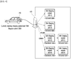
FIG. 4 , it may be assumed that acharger 420 includes four charging modules 430-1 to 430-4 having output current levels and a first electric vehicle to be charged 410 receives a charging current level of 100 A through two charging modules 430-1 and 430-2 from thecurrent charger 420. At this time, the level of the current requested by the first electric vehicle to be charged 410 may be increased to 200 A by various causes (e.g., a case where the user inputs an increase command of a vehicle charging rate/amount, etc.). In this case, thecharger 420 may determine the charging mode of the first electric vehicle to be charged 410 as the increase mode. - In addition, when the charging current level requested by the first electric vehicle to be charged is smaller than the sum of maximum output currents of the charging module while being currently connected to the first electric vehicle to be charged, the charger may determine a charging mode of the first electric vehicle to be charged as a decrease mode.
- For example, as illustrated in
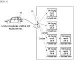
FIG. 5 , it may be assumed that acharger 510 includes four charging modules 530-1 to 530-4 having output current levels of 50 A and a first electric vehicle to be charged 510 receives a charging current level of 200A through the four charging modules 530-1 and 530-4 from the current charger. At this time, the level of the current requested by the first electric vehicle to be charged 510 may be decreased to 100 A by various causes (e.g., a case where the battery charging is completed by a predetermined ratio, etc.). In this case, acharger 520 may determine the charging mode of the first electric vehicle to be charged 510 as the decrease mode. - Next, the charger may charge the first electric vehicle to be charged in the charging mode determined in the previous step (S330).
- More specifically, when the increase mode is applied, the charger may selectively activate the charging modules by the number of rounding up a result obtained by dividing the charging current level requested by the first electric vehicle to be charged by the maximum output current and charge the first electric vehicle to be charged using the activated charging modules.
- For example, referring to
FIG. 4 , since the charging current level requested by the first electric vehicle to be charged 410 is 200 A and the maximum output current level is 50 A, four (= 200 A/50 A) charging modules 430-1 to 430-4 need to be activated. Since only two charging modules 430-1 and 430-2 are currently activated to charge the first electric vehicle to be charged 410, thecharger 420 is used to charge the first electric vehicle to be charged 410 by selectively activating two 430-3 and 430-4 of the charging modules to be currently deactivated. Accordingly, in the increase mode, the maximum number of charging modules to be selectively activated is limited to the number of charging modules which are currently being deactivated. - Similarly, when the decrease mode is applied, the charger may selectively deactivate charging modules as large as a number obtained by rounding up a result obtained by dividing the charging current level requested by the first electric vehicle to be charged by the maximum output current from the number of charging modules activated for charging of the first electric vehicle to be charged.
- For example, referring to
FIG. 5 , since the charging current level currently provided to the first electric vehicle to be charged 510 is 200 A, the requested charging current level is 100 A, and the maximum output current level is 50 A, two charging modules as a result obtained by subtracting 2 (= 100 A/50 A) from 4 (200 A/50 A) need to be deactivated. Since four charging modules 530-1 to 530-4 are currently activated to charge the first electric vehicle to be charged 510, thecharger 520 charges the first electric vehicle to be charged 510 by selectively deactivating two 530-3 and 530-4 of the four charging modules 530-1 to 530-4 activated. Accordingly, in the decrease mode, the maximum number of charging modules to be selectively deactivated is limited to the number of charging modules which are being currently activated to charge the first electric vehicle to be charged. - The charger converts an activated/deactivated state of the charging modules according to the charging mode of the electric vehicle to be charged, and at this time, the charger may perform activation/deactivation of the charging modules selectively based on an activated number and/or an activating cycle of each charging module.
- More specifically, the charger may first store second information on an activated number and/or an activating cycle of each of the plurality of charging modules. Based on the second information stored above, the charger may first select and activate a charging module activated at the least number and/or the rarest cycle of the plurality of charging modules when applying the increase mode. Further, the charger may first select and deactivate a charging module activated at the most number and/or the most frequent cycle among the plurality of charging modules when applying the decrease mode.
- As such, since the charger performs the activation/deactivation operation selectively by considering the activation cycle/frequency of each charging module, it is possible to prevent the intensive deterioration of some charging modules and equally manage the overall lifetime of the charging modules.
-
FIG. 6 is a diagram illustrating a power sharing operation according to an exemplary embodiment of the present disclosure. - As described above, a
charger 620 of the present disclosure includes a plurality of charging modules, and since each of these charging modules enables an independent charging operation, thecharger 620 may perform a power sharing function capable of simultaneously charging a plurality of electric vehicles 610-1 and 610-2 once. Accordingly, as the charging of a first electric vehicle to be charged 610-1 is completed, the sequentially deactivated charging module may be used to charge a second electric vehicle to be charged 610-2 which is a lower-priority charging target. - For example, referring to
FIG. 6 , when a charging current level currently received by the first electric vehicle to be charged 610-1 is 200 A and a request current is 100 A, a decrease mode may be applied, and as a result, two 50 A charging modules may be deactivated. The two charging modules deactivated as such may be used for charging the lower-priority electric vehicle to be charged 610-2. InFIG. 6 , since the current requested by the second electric vehicle to be charged 610-2 is 100 A, all of two charging modules may be used to charge the second electric vehicle to be charged 610-2. When the request current of the second electric vehicle to be charged 610-2 is 50 A, only one charging module may be activated for the second electric vehicle to be charged 610-2, and the remaining charging modules may be used for charging the next lower-priority electric vehicle to be charged. -
FIG. 7 is a graph showing a current detected from the charger when an inrush current occurs according to an exemplary embodiment of the present disclosure. - While the charger activates/deactivates the charging module, as illustrated in
FIG. 7 , an inrush current as a high level of current may be suddenly introduced. The inrush current is a very higher level of current than a reference charging current, and safety and maintenance problems are caused in the charging process of the electric vehicle. Particularly, in an electric vehicle charger for supplying a three-phase alternating current to the electric vehicle, an unnecessary operation of a circuit breaker and unnecessary tripping of an earth leakage breaker are caused in the charger due to the inrush current. Therefore, it is very important to prevent the inrush current in activating/deactivating the charging module. - The present disclosure provides an operation of a charger for preventing the inrush current, and will be described below with reference to
FIGS. 8 and9 . -
FIG. 8 is a graph showing an inrush current prevention operation when applying a decrease mode of the charger according to an exemplary embodiment of the present disclosure. - Referring to
FIG. 8 , the charger may first reduce a currently charging current level to a predetermined ratio A0 when applying the decrease mode to prevent the inrush current. Here, the predetermined ratio may correspond to, for example, 10% of the currently charging current level. - Next, the charger may check whether the inrush current occurs for a predetermined time t0. If it is checked that the inrush current does not occur for the predetermined time t0, the charger may deactivate the charging module which was intended to be deactivated. As a result, a maximum chargeable current of the charger is reduced by a maximum chargeable current of the deactivated charging module.
- Next, the charger may check whether the inrush current occurs according to the deactivation of the charging module again for a predetermined time t1. If it is checked that the inrush current does not occur for the predetermined time t1, the charger increases a charging current level by a charging current level requested by the first electric vehicle to be charged to return to an original charging operation/algorithm.
-
FIG. 9 is a graph showing an inrush current prevention operation when applying an increase mode of the charger according to an exemplary embodiment of the present disclosure. - Referring to
FIG. 9 , the charger may first reduce a currently charging current level to a predetermined ratio A0 when applying the increase mode to prevent an inrush current. Here, the predetermined ratio may correspond to, for example, 10% of the currently charging current level. - Next, the charger may check whether the inrush current occurs for a predetermined time t0. If it is checked that the inrush current does not occur for the predetermined time t0, the charger may activate the charging module which was intended to be activated. As a result, a maximum chargeable current of the charger is increased by a maximum chargeable current of the activated charging module.
- Next, the charger may check whether the inrush current occurs according to the activation of the charging module again for a predetermined time t1. If it is checked that the inrush current does not occur for the predetermined time t1, the charger increases a charging current level by a charging current level requested by the first electric vehicle to be charged to return to an original charging operation/algorithm.
- According to the exemplary embodiment of
FIGS. 8 and9 described above, the charger of the present disclosure has advantages of lowering the charging current level by a predetermined ratio before activating or deactivating the charging module to prevent the inrush current in advance and continuously detecting the inrush current before and after activating/deactivating to minimize the damage according to the occurrence of the inrush current. -
FIG. 10 is a block diagram illustrating a charger according to an exemplary embodiment of the present disclosure. - Hereinafter, configurations to be described below may be implemented by at least one hardware/software components and may be used to perform the exemplary embodiments described above.
- Referring to
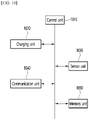
FIG. 10 , the charger may include a control unit 1010, acharging unit 1020, asensor unit 1030, acommunication unit 1040, and/or amemory unit 1050. - The control unit 1010 may not only communicate with other components included in the charger, but also may control the components. In particular, the control unit 1010 may subjectively perform various exemplary embodiments described in the present disclosure by controlling at least one component included in the charger. Accordingly, the charger of the present disclosure may be described to be identified with the control unit 1010. The control unit 1010 may be implemented by at least one processor.
- The
charging unit 1020 may include a hardware component necessary for charging the electric vehicle. For example, thecharging unit 1020 may include a plurality of charging modules and a charging connection unit for connecting the electric vehicle and the charger to supply power. - The
sensor unit 1030 senses a peripheral environment inside/outside the charger and may transmit a sensing result to the control unit. For example, thesensor unit 1030 may include at least one current/voltage detection sensor, and may monitor an internal current/voltage in real time to notify the result to the control unit. In particular, thesensor unit 1030 may sense the inrush current before and after activation/deactivation of the charging module and transmit the result to the control unit 1010. - The
communication unit 1040 may perform communication with the outside using at least one communication protocol. In particular, thecommunication unit 1040 may perform the communication using PLC, CAN, WiFi, Bluetooth, and NFC, as at least one communication protocol. Thecommunication unit 1040 may transmit a signal/information/data transmitted and received through communication to the control unit and may transmit the signal/information/data received from the control unit 1010 to the outside. - The
memory unit 1050 may store various information/data/programs/applications, and the like. Thememory unit 1050 may transmit the stored information/data to the control unit or receive the stored information/data from the control unit 1010. Particularly, thememory unit 1050 according to the present disclosure may store information/data on frequency/number/period, and the like at which each charging module is activated (or deactivated). - Meanwhile, for convenience of description, in the present disclosure, in
FIGS. 1 and6 , etc., an exemplary embodiment in which a plurality of connection terminals is provided in one charger and one charger is connected with a plurality of electric vehicles through the plurality of connection terminals has been illustrated, but is not limited thereto. Of course, a plurality of dispensers is provided in one charger and the charger may also be connected with the plurality of electric vehicles through the plurality of dispensers. - Although the drawings have been described for the sake of convenience of explanation, it is also possible to design a new exemplary embodiment to be implemented by merging the exemplary embodiments described in each drawing. Further, configurations and methods of the described exemplary embodiments may not be limitedly applied to the aforementioned present disclosure, but all or some of the respective exemplary embodiments may be selectively combined and configured so as to be variously modified.
- Further, while the exemplary embodiments of the present disclosure have been illustrated and described above, the present disclosure is not limited to the aforementioned specific exemplary embodiments, various modifications may be made by a person with ordinary skill in the technical field to which the present disclosure pertains without departing from the subject matters of the present disclosure that are claimed in the claims, and these modifications should not be appreciated individually from the technical spirit or prospect of the present disclosure.
- The present disclosure may be applied to various electric vehicle charging technical fields and inrush current prevention technical fields.
Claims (29)
- A method for preventing an inrush current of an electric vehicle charger comprising steps of:determining whether there is a need for an increase or decrease in a charging current level while currently supplied to a electric vehicle to be charged according to a request of the electric vehicle to be charged;decreasing the charging current level at a predetermined ratio when it is determined that there is the need for the increase or decrease in the charging current level;checking whether an inrush current occurs for a first time;activating or deactivating at least one charging module to increase or decrease the charging current level according to the request of the electric vehicle to be charged, when the inrush current does not occur for the first time;checking whether the inrush current occurs for a second time; andincreasing the charging current level by the charging current level requested by the electric vehicle to be charged, when the inrush current does not occur for the second time.
- The method for preventing an inrush current of the electric vehicle charger of claim 1, wherein the inrush current corresponds to a higher level of current than a predefined reference current by a predetermined level or more.
- The method for preventing an inrush current of the electric vehicle charger of claim 1, wherein the predetermined ratio corresponds to 10% of the charging current level.
- The method for preventing an inrush current of the electric vehicle charger of claim 1, wherein the determining of whether there is the need for the increase or decrease of the charging current level includes steps ofcomparing a current level requested by the electric vehicle to be charged with the charging current level;determining that there is the need for the decrease of the charging current level when the requested current level is less than the charging current level; anddetermining that there is the need for the increase of the charging current level when the requested current level is more than the charging current level.
- The method for preventing an inrush current of the electric vehicle charger of claim 4, wherein the activating or deactivating of the at least one charging module includes steps ofselectively deactivating at least one of currently activating charging modules when it is determined that there is the need for the decrease of the charging current level; andselectively activating at least one of currently deactivating charging modules when it is determined that there is the need for the increase of the charging current level.
- The method for preventing an inrush current of the electric vehicle charger of claim 5, wherein the selectively deactivating of at least one of the currently activating charging modules includes selectively deactivating first at least one charging module activated at the most number and/or the most frequent cycle among the currently activating charging modules.
- The method for preventing an inrush current of the electric vehicle charger of claim 5, wherein the selectively activating of at least one of the currently deactivating charging modules includes selectively activating first a charging module activated in at least one of the least number and the rarest cycle among the currently deactivating charging modules.
- The method for preventing an inrush current of the electric vehicle charger of claim 5, further comprising:
recording information on at least one of an activation number and an activation cycle of the at least one charging module. - An electric vehicle charger comprising:a charging unit including a plurality of charging modules;a communication unit performing communication with an electric vehicle to be charged; anda control unit controlling the charging unit and the communication unit,wherein the control unit:determines whether there is a need for an increase or decrease in a charging current level while currently supplied to the electric vehicle to be charged according to a request of the electric vehicle to be charged received by the communication unit,decreases the charging current level at a predetermined ratio by controlling the charging unit when it is determined that there is the need for the increase or decrease in the charging current level,checks whether an inrush current occurs for a first time,activates or deactivates at least one charging module by controlling the charging unit to increase or decrease the charging current level according to the request of the electric vehicle to be charged, when the inrush current does not occur for the first time,checks whether the inrush current occurs for a second time, andincreases the charging current level by the charging current level requested by the electric vehicle to be charged by controlling the charging unit, when the inrush current does not occur for the second time.
- The electric vehicle charger of claim 9, wherein the inrush current corresponds to a higher level of current than a predefined reference current by a predetermined level or more.
- The electric vehicle charger of claim 9, wherein the predetermined ratio corresponds to 10% of the charging current level.
- The electric vehicle charger of claim 9, wherein when it is determined that there is the need for the increase or decrease of the charging current level, the control unitcompares a current level requested by the electric vehicle to be charged with the charging current level,determines that there is the need for the decrease of the charging current level when the requested current level is less than the charging current level, anddetermines that there is the need for the increase of the charging current level when the requested current level is more than the charging current level.
- The charging method of the electric vehicle charger of claim 12, wherein when activating or deactivating the at least one charging module, the control unitselectively deactivates at least one of currently activating charging modules when it is determined that there is the need for the decrease of the charging current level, andselectively activates at least one of currently deactivating charging modules when it is determined that there is the need for the increase of the charging current level.
- The electric vehicle charger of claim 13, wherein when selectively deactivating at least one of the currently activating charging modules, the control unit
selectively deactivates first at least one charging module activated at the most number and/or the most frequent cycle among the currently activating charging modules. - The electric vehicle charger of claim 13, wherein when selectively activating at least one of the currently deactivating charging modules, the control unit
selectively activates first a charging module activated in at least one of the least number and the rarest cycle among the currently deactivating charging modules. - The electric vehicle charger of claim 13, wherein the control unit records information on at least one of an activation number and an activation cycle of the at least one charging module.
- A charging method of an electric vehicle charger comprising steps of:receiving first information on a charging current level requested by a first electric vehicle to be charged from the first electric vehicle to be charged;determining a charging mode of the first electric vehicle to be charged based on the first information, wherein the charging mode includesan increase mode of charging the first electric vehicle to be charged by selectively activating at least one deactivating charging module among the plurality of charging modules and a decrease mode of selectively deactivating at least one charging module activated to charge the first electric vehicle to be charged; andcharging the first electric vehicle to be charged in the determined charging mode.
- The charging method of the electric vehicle charger of claim 17, wherein the plurality of charging modules has all the same maximum output current.
- The charging method of the electric vehicle charger of claim 18, wherein in the determining of the charging mode, the charging modeis determined as the increase mode when the charging current level requested by the first electric vehicle to be charged is larger than a sum of maximum output currents of the charging module while being currently connected to the first electric vehicle to be charged, andis determined as the decrease mode when the charging current level requested by the first electric vehicle to be charged is smaller than the sum of maximum output currents of the charging module while being currently connected to the first electric vehicle to be charged.
- The charging method of the electric vehicle charger of claim 19, wherein when the increase mode is applied, the charging of the first electric vehicle to be charged includes
selectively activating the charging modules by the number of rounding up a result obtained by dividing the charging current level requested by the first electric vehicle to be charged by the maximum output current and charging the first electric vehicle to be charged using the activated charging modules. - The charging method of the electric vehicle charger of claim 20, wherein in the increase mode, the maximum number of charging modules to be selectively activated is limited to the number of charging modules which are currently being deactivated.
- The charging method of the electric vehicle charger of claim 21, wherein when the decrease mode is applied, the charging of the first electric vehicle to be charged includes
selectively deactivating charging modules as large as a number obtained by rounding up a result obtained by dividing the charging current level requested by the first electric vehicle to be charged by the maximum output current from the number of charging modules activated for charging of the first electric vehicle to be charged. - The charging method of the electric vehicle charger of claim 22, wherein in the decrease mode, the maximum number of charging modules to be selectively deactivated is limited to the number of charging modules which are being currently activated to charge the first electric vehicle to be charged.
- The charging method of the electric vehicle charger of claim 23, further comprising:
using a charging module selectively deactivated as the decrease mode is applied for charging of a second electric vehicle to be charged which is a lower-priority charging target. - The charging method of the electric vehicle charger of claim 24, further comprising:
storing second information on an activated number and/or an activating cycle of each of the plurality of charging modules. - The charging method of the electric vehicle charger of claim 25, wherein based on the second information,in the case of the increase mode, a charging module activated at the least number and/or the rarest cycle of the plurality of charging modules is first selected and activated, andin the case of the decrease mode, a charging module activated at the most number and/or the most frequent cycle among the plurality of charging modules is first selected and deactivated.
- The charging method of the electric vehicle charger of claim 26, wherein the charging step includes steps ofdecreasing a currently charging current level for the first electric vehicle to be charged at a predetermined ratio before activating or deactivating the at least one charging module;checking whether an inrush current occurs for a first time;activating or deactivating the at least one charging module when the inrush current does not occur;checking whether the inrush current occurs for a second time after activating or deactivating; andincreasing the charging current level by the charging current level requested by the first electric vehicle to be charged, when the inrush current does not occur.
- The charging method of the electric vehicle charger of claim 27, wherein the predetermined ratio corresponds to 10% of the currently charging current level.
- An electric vehicle charger comprising:a charging unit including a plurality of charging modules;a communication unit performing communication with an electric vehicle to be charged; anda control unit controlling the charging unit and the communication unit,wherein the control unitreceives first information on a charging current level requested by a first electric vehicle to be charged from the first electric vehicle to be charged,determines a charging mode of the first electric vehicle to be charged based on the first information, wherein the charging mode includesan increase mode of charging the first electric vehicle to be charged by selectively activating at least one deactivating charging module among the plurality of charging modules and a decrease mode of selectively deactivating at least one charging module activated to charge the first electric vehicle to be charged, andcharges the first electric vehicle to be charged in the determined charging mode.
Applications Claiming Priority (3)
| Application Number | Priority Date | Filing Date | Title |
|---|---|---|---|
| KR1020200122162A KR102267043B1 (en) | 2020-09-22 | 2020-09-22 | An electric vehicle charging method using a plurality of charging modules and apparatus therefor |
| KR1020210076934A KR102319685B1 (en) | 2020-09-22 | 2021-06-14 | Inrush current prevention method and device therefor |
| PCT/KR2021/007759 WO2022065634A1 (en) | 2020-09-22 | 2021-06-21 | Electric vehicle charging method for preventing inrush current and device therefor |
Publications (2)
| Publication Number | Publication Date |
|---|---|
| EP4001000A1 true EP4001000A1 (en) | 2022-05-25 |
| EP4001000A4 EP4001000A4 (en) | 2023-07-26 |
Family
ID=76623746
Family Applications (1)
| Application Number | Title | Priority Date | Filing Date |
|---|---|---|---|
| EP21806125.7A Pending EP4001000A4 (en) | 2020-09-22 | 2021-06-21 | Electric vehicle charging method for preventing inrush current and device therefor |
Country Status (6)
| Country | Link |
|---|---|
| US (1) | US11605958B2 (en) |
| EP (1) | EP4001000A4 (en) |
| JP (1) | JP7216844B2 (en) |
| KR (2) | KR102267043B1 (en) |
| GB (1) | GB2615437A (en) |
| WO (1) | WO2022065634A1 (en) |
Families Citing this family (2)
| Publication number | Priority date | Publication date | Assignee | Title |
|---|---|---|---|---|
| KR102267043B1 (en) * | 2020-09-22 | 2021-06-18 | (주)시그넷이브이 | An electric vehicle charging method using a plurality of charging modules and apparatus therefor |
| KR102406394B1 (en) * | 2021-09-01 | 2022-06-08 | 에스케이시그넷 주식회사 | Big data-based central control charging system, method and device |
Family Cites Families (33)
| Publication number | Priority date | Publication date | Assignee | Title |
|---|---|---|---|---|
| JP2837307B2 (en) * | 1992-03-13 | 1998-12-16 | 株式会社日立製作所 | Vehicle charging generator |
| JP3267232B2 (en) * | 1998-02-23 | 2002-03-18 | 日本電気株式会社 | Power supply control method and power supply control device for inrush current suppression |
| JP2002017001A (en) | 2000-06-30 | 2002-01-18 | Okamura Kenkyusho:Kk | Charging and controlling method by electricity storing device in hybrid electric vehicle |
| JP2003153588A (en) | 2001-11-09 | 2003-05-23 | Nissan Motor Co Ltd | Motor driver |
| US7756681B2 (en) * | 2005-03-10 | 2010-07-13 | Hewlett-Packard Development Company, L.P. | Power supply circuit |
| US7593265B2 (en) | 2007-12-28 | 2009-09-22 | Sandisk Corporation | Low noise sense amplifier array and method for nonvolatile memory |
| JP5158948B2 (en) * | 2008-03-11 | 2013-03-06 | 矢崎総業株式会社 | Electrical junction box, power supply cutoff method, and program |
| US8239700B2 (en) * | 2009-04-17 | 2012-08-07 | Lsi Corporation | Systems and methods for power dissipation control in a semiconductor device |
| US8315745B2 (en) * | 2009-04-24 | 2012-11-20 | Hunter Defense Technologies, Inc. | Mobile micro-grid power system controller and method |
| EP2551987A4 (en) * | 2010-03-23 | 2015-12-23 | Panasonic Corp | Charging control apparatus, charging system, and charging control method |
| CN102255347A (en) | 2010-05-19 | 2011-11-23 | 日立信息能源系统有限公司 | Chariging equipment |
| JP5647057B2 (en) * | 2010-05-19 | 2014-12-24 | 株式会社日立製作所 | Charging apparatus, charging control unit, and charging control method |
| JP5863015B2 (en) | 2011-10-17 | 2016-02-16 | シンフォニアテクノロジー株式会社 | Charging equipment |
| JP5524166B2 (en) * | 2011-12-02 | 2014-06-18 | 中国電力株式会社 | Charge control device for multiple ordinary chargers |
| NL2008058C2 (en) * | 2011-12-29 | 2013-07-03 | Epyon B V | Method, system and charger for charging a battery of an electric vehicle. |
| US8717001B2 (en) * | 2012-07-03 | 2014-05-06 | Infineon Technologies Austria Ag | Inrush current limiting circuit |
| JP5806779B2 (en) * | 2012-10-15 | 2015-11-10 | 川崎重工業株式会社 | Electric vehicle |
| CN104253464B (en) | 2013-06-28 | 2017-05-03 | 比亚迪股份有限公司 | System for mutual charging of electric vehicles and charging connector |
| US9180781B2 (en) * | 2013-11-13 | 2015-11-10 | Honda Motor Co., Ltd. | Electric automobile |
| CN106132761B (en) * | 2014-03-27 | 2018-10-09 | 本田技研工业株式会社 | Electric vehicle and vehicle method of supplying power to |
| JP5918330B2 (en) | 2014-10-01 | 2016-05-18 | 株式会社東光高岳 | Electric mobile charging device |
| KR102331727B1 (en) | 2015-06-29 | 2021-11-26 | 삼성에스디아이 주식회사 | Battery Pack and Charge Controlling System for Electric Vehicle Including Thereof |
| JP2017103976A (en) * | 2015-12-04 | 2017-06-08 | トヨタ自動車株式会社 | Charger |
| US10259336B2 (en) * | 2016-10-18 | 2019-04-16 | Ford Global Technologies, Llc | Charging a battery using interpack switch |
| KR102072904B1 (en) | 2017-02-28 | 2020-02-04 | 김홍식 | Power-loop train system for electric vehicle and method for operating electric vehicle using the same |
| JP6474455B2 (en) * | 2017-05-01 | 2019-02-27 | ファナック株式会社 | Converter device for optimizing initial charging time of DC link capacitor |
| US10566787B2 (en) * | 2017-10-25 | 2020-02-18 | Abb S.P.A. | Inrush current detection and control with solid-state switching devices |
| KR20190056084A (en) | 2017-11-16 | 2019-05-24 | 르노삼성자동차 주식회사 | Multi charger for electric vehicle and method of generating control signal for multi charging |
| CN109455106B (en) * | 2018-10-17 | 2022-07-26 | 国网浙江省电力有限公司杭州供电公司 | Intelligent charging station for electric automobile |
| KR20190078550A (en) * | 2019-02-20 | 2019-07-04 | 김성두 | Charging apparatus for vehicles |
| KR102003360B1 (en) * | 2019-03-11 | 2019-07-24 | (주)시그넷이브이 | Elecric vehecle chaging method of vehicle charging system |
| KR20200113864A (en) * | 2019-03-26 | 2020-10-07 | 삼성전자주식회사 | Wireless power receiving device and method for controlling thereof |
| KR102267043B1 (en) * | 2020-09-22 | 2021-06-18 | (주)시그넷이브이 | An electric vehicle charging method using a plurality of charging modules and apparatus therefor |
-
2020
- 2020-09-22 KR KR1020200122162A patent/KR102267043B1/en active IP Right Grant
-
2021
- 2021-06-14 KR KR1020210076934A patent/KR102319685B1/en active IP Right Grant
- 2021-06-21 GB GB2305770.6A patent/GB2615437A/en active Pending
- 2021-06-21 EP EP21806125.7A patent/EP4001000A4/en active Pending
- 2021-06-21 JP JP2021571516A patent/JP7216844B2/en active Active
- 2021-06-21 WO PCT/KR2021/007759 patent/WO2022065634A1/en unknown
- 2021-11-29 US US17/536,949 patent/US11605958B2/en active Active
Also Published As
| Publication number | Publication date |
|---|---|
| KR102319685B1 (en) | 2021-11-01 |
| US11605958B2 (en) | 2023-03-14 |
| WO2022065634A1 (en) | 2022-03-31 |
| EP4001000A4 (en) | 2023-07-26 |
| KR102267043B1 (en) | 2021-06-18 |
| JP2022548807A (en) | 2022-11-22 |
| GB2615437A (en) | 2023-08-09 |
| JP7216844B2 (en) | 2023-02-01 |
| GB202305770D0 (en) | 2023-05-31 |
| US20220166240A1 (en) | 2022-05-26 |
Similar Documents
| Publication | Publication Date | Title |
|---|---|---|
| US11605958B2 (en) | Electric vehicle charging method for preventing inrush current and device for the same | |
| US10189367B2 (en) | Electric vehicle quick charge control apparatus | |
| KR20020097022A (en) | Method for controlling battery charge and discharge | |
| CN107719125B (en) | Vehicle | |
| CN102753379A (en) | Power supply system for electric vehicle, and control method thereof | |
| US9682634B2 (en) | Method and system for detecting charger | |
| US20120256611A1 (en) | Power supply apparatus and method of controlling the same | |
| JP5470193B2 (en) | Quick charger | |
| US9919604B2 (en) | Power net system of fuel cell vehicle and method for controlling the same | |
| US11345255B2 (en) | Emergency electric power supply system, emergency electric power supply method, and storage medium | |
| KR20170072992A (en) | Electric Vehicle Charging Cable Control Apparatus and Electric Vehicle Power Charging Controlling System | |
| CN104369702A (en) | Apparatus and method for driving vehicle | |
| US20170054316A1 (en) | System and method of charging battery | |
| JP2014033555A (en) | Charging system | |
| CN115946565A (en) | Brand identification in recharging electric vehicles | |
| JP2016140156A (en) | Controller for power storage device | |
| US20200274206A1 (en) | Battery device | |
| US11884164B2 (en) | System and method for controlling charging of battery of eco-friendly vehicle | |
| KR20120101820A (en) | Apparatus for charging battery and method for controlling charge battery of the same | |
| CN112319300A (en) | Intelligent charger and intelligent charging management method thereof | |
| JP5880049B2 (en) | Charging system | |
| KR100270559B1 (en) | Battery equalization method | |
| US20230001795A1 (en) | Reducing switching-on and switching-off processes in an electric drivetrain | |
| JP7263988B2 (en) | Charging rate estimator | |
| JP5933348B2 (en) | Charging system |
Legal Events
| Date | Code | Title | Description |
|---|---|---|---|
| STAA | Information on the status of an ep patent application or granted ep patent |
Free format text: STATUS: UNKNOWN |
|
| STAA | Information on the status of an ep patent application or granted ep patent |
Free format text: STATUS: THE INTERNATIONAL PUBLICATION HAS BEEN MADE |
|
| PUAI | Public reference made under article 153(3) epc to a published international application that has entered the european phase |
Free format text: ORIGINAL CODE: 0009012 |
|
| STAA | Information on the status of an ep patent application or granted ep patent |
Free format text: STATUS: REQUEST FOR EXAMINATION WAS MADE |
|
| 17P | Request for examination filed |
Effective date: 20211124 |
|
| AK | Designated contracting states |
Kind code of ref document: A1 Designated state(s): AL AT BE BG CH CY CZ DE DK EE ES FI FR GB GR HR HU IE IS IT LI LT LU LV MC MK MT NL NO PL PT RO RS SE SI SK SM TR |
|
| RAP3 | Party data changed (applicant data changed or rights of an application transferred) |
Owner name: SK SIGNET INC. |
|
| A4 | Supplementary search report drawn up and despatched |
Effective date: 20230623 |
|
| RIC1 | Information provided on ipc code assigned before grant |
Ipc: B60L 53/62 20190101ALI20230619BHEP Ipc: B60L 53/30 20190101ALI20230619BHEP Ipc: B60L 53/64 20190101ALI20230619BHEP Ipc: B60L 53/67 20190101AFI20230619BHEP |
|
| DAV | Request for validation of the european patent (deleted) | ||
| DAX | Request for extension of the european patent (deleted) |